Embed Size (px)
Citation preview
Code No. 0816836Rev. 0 (07/09)
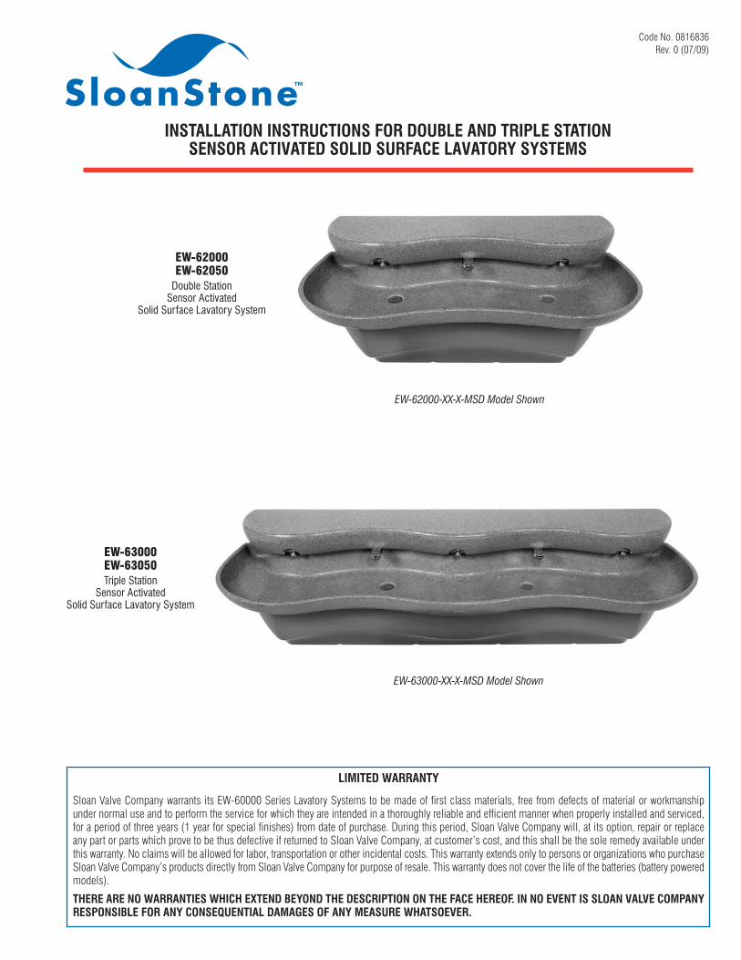
INSTALLATION INSTRUCTIONS FOR DOUBLE AND TRIPLE STATIONSENSOR ACTIVATED SOLID SURFACE LAVATORY SYSTEMS
LIMITED WARRANTY
Sloan Valve Company warrants its EW-60000 Series Lavatory Systems to be made of first class materials, free from defects of material or workmanshipunder normal use and to perform the service for which they are intended in a thoroughly reliable and efficient manner when properly installed and serviced,for a period of three years (1 year for special finishes) from date of purchase. During this period, Sloan Valve Company will, at its option, repair or replaceany part or parts which prove to be thus defective if returned to Sloan Valve Company, at customer’s cost, and this shall be the sole remedy available underthis warranty. No claims will be allowed for labor, transportation or other incidental costs. This warranty extends only to persons or organizations who purchaseSloan Valve Company’s products directly from Sloan Valve Company for purpose of resale. This warranty does not cover the life of the batteries (battery poweredmodels).
THERE ARE NO WARRANTIES WHICH EXTEND BEYOND THE DESCRIPTION ON THE FACE HEREOF. IN NO EVENT IS SLOAN VALVE COMPANYRESPONSIBLE FOR ANY CONSEQUENTIAL DAMAGES OF ANY MEASURE WHATSOEVER.
EW-62000EW-62050
Double StationSensor Activated
Solid Surface Lavatory System
EW-63000EW-63050Triple Station
Sensor ActivatedSolid Surface Lavatory System
EW-62000-XX-X-MSD Model Shown
EW-63000-XX-X-MSD Model Shown

2
1-1/2” (38 mm)
DRAIN (2)
6 ” (152 mm)
1/2” HOT/COLD
SUPPLY LINES
FACEOF
WALL
11-1/4” (286 mm)
21”(533 mm)
11-1/4” (286 mm)
C/L OF DRAIN
CENTERLINEC/L OF DRAIN
50” (1270 mm)
11-1/8”(283 mm)
D (SEE
CHART)
C (SEE
CHART)
14-3/4” (375 mm)
OPTIONAL LIQUID SOAP DISPENSER FILL
110 VOLT, 60 Hz ,
15 AMP, GFCI PROTECTED ELECTRICAL
OUTLET (BY OTHERS)
A (SEE
CHART)
24-7/8”(632 mm)
6-5/16”(160 mm)
8-1/4” (210 mm)
B (SEE CHART)
PLASTIC CABINET
PLASTIC CABINET
14-3/4” (375 mm)
FINISHEDFLOOR
LAVATORY SYSTEM ROUGH-IN
MODEL EW-62000MODEL EW-62050
Double Station Lavatory SystemFlow Rate: 0.5 gpm/1.9 Lpm Max. Spray
Lavatory System Weight (Packaged): Approximately 82 Lbs/37 Kg
CENTERLINE
11-1/4” (286 mm)
11-1/4” (286 mm)
76” (1930 mm)
OPTIONAL LIQUID SOAP DISPENSER FILL
FACE OF
WALL
1/2” HOT/COLD
SUPPLY LINES
21-1/4”(540 mm)
1-1/2” (38 mm) DRAIN (2)
14-3/4”(375 mm)
6”(152 mm)
14-3/4”(375 mm)
B(SEE CHART)
110 VOLT, 60 Hz, 15 AMP, GFCI PROTECTED ELECTRICAL
OUTLET (BY OTHERS)
A(SEE
CHART)
21”(533 mm)
D (SEE
CHART)
C (SEE
CHART)
24”(610 mm)
6-5/16”(160 mm)
11-1/8”(283 mm)
PLASTIC CABINET
PLASTIC CABINET
FINISHEDFLOOR
MODEL EW-63000MODEL EW-63050
Triple Station Lavatory SystemFlow Rate: 0.5 gpm/1.9 Lpm Max. Spray
Lavatory System Weight (Packaged): Approximately 124 Lbs/56 Kg
VARIABLE MOUNTING HEIGHT CHART (2 AND 3 STATION)DIMENSION T.A.S. † T.A.S. † A.D.A.DESCRIPTION AGES 4-10 AGES 11-15 STANDARD
A ROUGH-IN, DRAIN 20” (508 mm) 22” (559 mm) 24” (610 mm)B ROUGH-IN, SUPPLY 23” (584 mm) 25” (635 mm) 27” (686 mm)C RECOMMENDED RIM HEIGHT 29-3/4” (756 mm) 31-3/4” (806 mm) 33-3/4” (857 mm)D FLOOR CLEARANCE, 2 STATION 11-1/8” (283 mm) 13-1/8” (333 mm) 15-1/8” (384 mm)D FLOOR CLEARANCE, 3 STATION 12-1/16” (306 mm) 14-1/16” (357 mm) 16-1/16” (408 mm)E BRACKETS, HEIGHT ‡ 25-3/4” (654 mm) 27-3/4” (705 mm) 29-3/4” (756 mm)F BRACKETS, TOP HOLE ‡ 25” (635 mm) 27” (686 mm) 29” (737 mm)
† When no mirror is required above the basin.‡ Refer to Step 2.

3
PRIOR TO INSTALLATIONPrior to installing the Sloan EW-60000 Series Lavatory System, installthe items listed below. Also, refer to the appropriate rough-in diagram onPage 2 and brackets diagram on Page 4.• Install electrical receptacle(s) for plug-in transformer(s) — 120 VAC,
2 amp service for each SFP-36 (6 VDC, 2300 mA) plug-in transformerused (EW-62000/EW-63000 only).
• Hot and cold water supply lines or tempered water supply line (If thereis no tempered water supply, install mechanical mixing valve betweenhot and cold water supply)
• Drain lines
Important:• ADEQUATE STRUCTURAL SUPPORT IN OR BEHIND THE WALL IS
REQUIRED. REFER TO THE APPROPRIATE ROUGH-IN DIAGRAM ONPAGE 2 FOR DRY WEIGHT OF SINK. STRUCTURAL SUPPORTMUST HAVE A MINIMUM PULLOUT RATING OF 1000 POUNDS(450 Kg) FOR EACH FASTENER.
• INSTALL ALL ELECTRICAL WIRING IN ACCORDANCE WITHNATIONAL/LOCAL CODES AND REGULATIONS.
• INSTALL ALL PLUMBING IN ACCORDANCE WITH APPLICABLE CODESAND REGULATIONS.
• USE APPROPRIATE PRECAUTIONS WHILE CONNECTINGTRANSFORMER TO 120 VAC POWER SOURCE.
• DO NOT PLUG TRANSFORMER INTO POWER SOURCE (RECEPTACLE)UNTIL ALL WIRING IS COMPLETED.
• BEFORE CONNECTING FLEX HOSES TO SUPPLY STOPS, FLUSH ALLWATER LINES UNTIL WATER IS CLEAR.
TOOLS REQUIRED FOR INSTALLATION• Electric drill for drilling anchor holes.• Standard sockets and open-end wrench set for installing anchoring
fasteners and connecting water lines.• Pipe wrench for installing drain lines.• Phillips and straight blade screwdrivers.• Tubing Cutter• Level• Carpenter’s square• Caulk gun
SINK LOCATIONDetermine the appropriate wall location for the Lavatory System.Consider that hot and cold water supply lines, drain lines, and anelectrical source (receptacle) will be required. Compare the physicaldimensions of the Lavatory System to the space available for theinstallation. If wall is not load-bearing, a carrier may be required behindthe wall. Refer to the appropriate Rough-in diagram on Page 2 forLavatory System dimensions.Prior to Lavatory System installation, electric wiring, water supply anddrain must be installed.
1 Install Mechanical Mixing Valve
A If there is no tempered water supply, install Mechanical Mixing Valve between hot and cold water supply.
MIX-60-A MECHANICAL MIXING VALVE

4
2 Mount Brackets and Basin to Wall
1/4”-20 x 1/2” Truss Head Screw (Actual Size)
2-1/2” (64 mm)
1-1/4” (32 mm)
32” (813 mm) APPROXIMATE LOCATION
32-1/4” (819 mm) APPROXIMATE LOCATION1/8” (3 mm)
APPROXIMATE LOCATION
8-3/4” (222 mm) APPROXIMATE LOCATION
7-1/2” (191 mm)
“F”SEE TABLE ON
PAGE 2
2-1/2” (64 mm)
1-1/4” (32 mm)
3-3/8” (86 mm) APPROXIMATE LOCATION
8-3/4” (222 mm) APPROXIMATE LOCATION
7-1/2” (191 mm)
DISTANCE BETWEEN BRACKETS - STEP 2B
32” (813 mm) APPROXIMATE LOCATION
FINISHED FLOOR
HEAD SECURING LOCATIONS (2)
HEAD SECURING LOCATIONS (3)
FINISHED FLOOR
“F”SEE TABLE ON
PAGE 2
DISTANCE BETWEEN BRACKETS - STEP 2B
DISTANCE BETWEEN BRACKETS - STEP 2B
DISTANCE BETWEEN BRACKETS - STEP 2B
D Mount Basin and Brackets to wall using fasteners with washers that hold over 1000 lbf (pounds-force) withdrawal load each.Note: If desired, detach Brackets from Basin and mount Brackets to wall first. Then mount Basin to Brackets using 1/4”-20 x 1/2” Truss Head Screws.Grid Strainer may be installed prior to attaching Basin to Brackets. Refer to Step 3.
E Level Brackets in all directions before tighteningfasteners securely. If desired,apply caulk between Basinand Wall.
Note: If installation is on soft wallplace 1/16” thick stainless orgalvanized steel sheets between theWall and the Brackets. These sheetsmust be larger in area than themounting surfaces of the Brackets,and must have thru-holes that alignwith the Bracket’s mounting holes.
A Attach Brackets to Basin using 1/4”-20 x 1/2”Truss Head Screws. Double Station uses six(6) Fasteners. Triple Station uses eight (8)Fasteners.
B Measure distance between brackets. Makesure the carrier (when needed) canaccommodate the proper location for thebrackets.
C Determine the appropriate location for the holes to secure the brackets to the wall. Use the following dimensions as a reference.
DOUBLE STATION
DOUBLE STATION
TRIPLE STATION
TRIPLE STATION
1/4”-20 x 1/2” TRUSS HEAD SCREWS (6)
1/4”-20 x 1/2” TRUSS HEAD SCREWS (8)
DISTANCE BETWEENBRACKETS
DISTANCE BETWEENBRACKETS
5
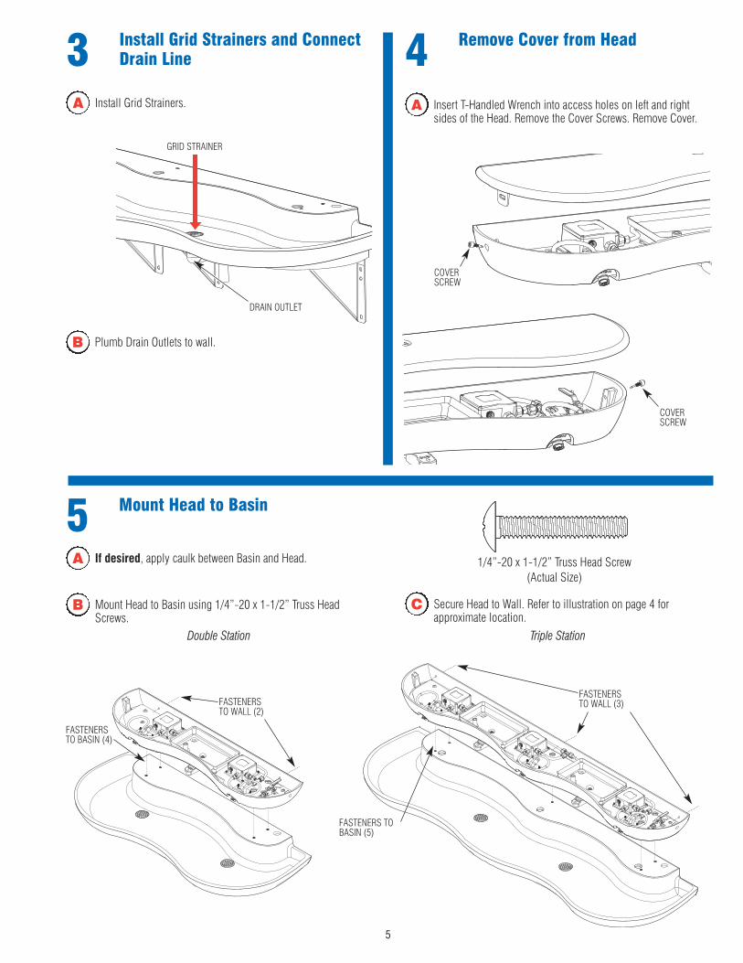
4 Remove Cover from Head3 Install Grid Strainers and ConnectDrain Line
A Insert T-Handled Wrench into access holes on left and rightsides of the Head. Remove the Cover Screws. Remove Cover.
A Install Grid Strainers.
DRAIN OUTLET
GRID STRAINER
COVERSCREW
COVERSCREW
B Plumb Drain Outlets to wall.
5 Mount Head to Basin
FASTENERSTO WALL (2)
A If desired, apply caulk between Basin and Head.
FASTENERSTO BASIN (4)
C Secure Head to Wall. Refer to illustration on page 4 forapproximate location.
FASTENERS TOBASIN (5)
FASTENERSTO WALL (3)
Triple StationDouble Station
1/4”-20 x 1-1/2” Truss Head Screw(Actual Size)
B Mount Head to Basin using 1/4”-20 x 1-1/2” Truss HeadScrews.
6
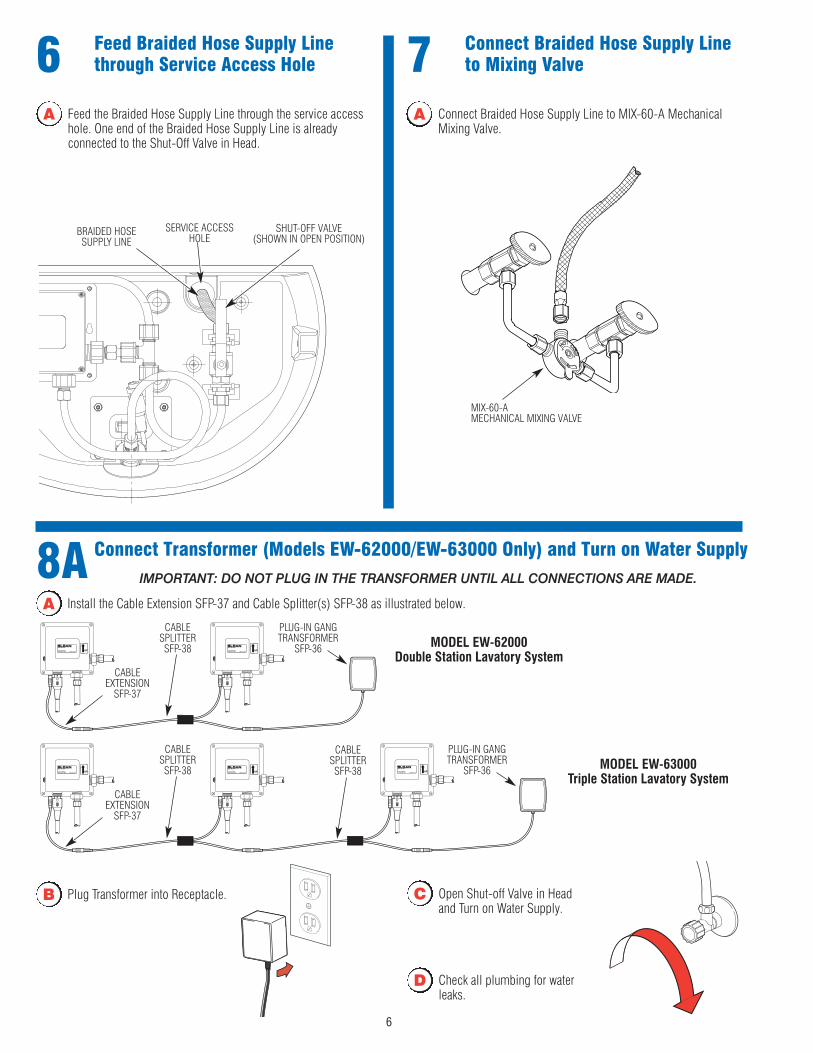
A Feed the Braided Hose Supply Line through the service accesshole. One end of the Braided Hose Supply Line is alreadyconnected to the Shut-Off Valve in Head.
6 Feed Braided Hose Supply Linethrough Service Access Hole
SERVICE ACCESSHOLE
SHUT-OFF VALVE (SHOWN IN OPEN POSITION)
7 Connect Braided Hose Supply Lineto Mixing Valve
A Connect Braided Hose Supply Line to MIX-60-A MechanicalMixing Valve.
BRAIDED HOSESUPPLY LINE
8A Connect Transformer (Models EW-62000/EW-63000 Only) and Turn on Water Supply
A Install the Cable Extension SFP-37 and Cable Splitter(s) SFP-38 as illustrated below.
IMPORTANT: DO NOT PLUG IN THE TRANSFORMER UNTIL ALL CONNECTIONS ARE MADE.
C Open Shut-off Valve in Headand Turn on Water Supply.
D Check all plumbing for waterleaks.
PLUG-IN GANGTRANSFORMER
SFP-36
CABLESPLITTERSFP-38
CABLEEXTENSION
SFP-37
MIX-60-A MECHANICAL MIXING VALVE
MODEL EW-62000 Double Station Lavatory System
PLUG-IN GANGTRANSFORMER
SFP-36
CABLESPLITTERSFP-38
CABLEEXTENSION
SFP-37
MODEL EW-63000 Triple Station Lavatory System
CABLESPLITTERSFP-38
B Plug Transformer into Receptacle.

7
8B Install Batteries (Models EW-62050 / EW-63050 Only)
A Loosen CoverScrews andremove Coverfrom ControlModule.
B Remove Battery Compartment and install four (4) AA-sizebatteries (supplied) as indicated by the (+) and (-) symbolsinside the Battery Compartment.
C Reinstall Battery Compartment into the Control Module. Makesure that the electrical contacts are facing up.
D Reinstall Control Module Cover using all four (4) Screws.
11 Test Faucet Operation
A Place hands under spout. Solenoid valve should “click”, LED insensor window should blink once and water should flow fromthe spout.
B Release the red button when the sensor starts flashing.
9 Set Range Adjustment
10 Set Water Flow Time-Out
A Hold the red button in for more than six (6) seconds. The waterflow time-out settings will change from 7 seconds to 70seconds or from 70 seconds to 7 seconds.
B When hands are removed, the water flow should stop.
Note: Sensor Range can be adjusted after power is supplied to theFaucet (battery or hardwire).
Note: The Sensor rangeis dependent on thedistance of your hand orcard while the sensor isin range setting mode.
Note: If no target is placed in front of the sensor, the sensor range willset to its longest distance.
Note: There are two available time-out settings: 7 seconds and 70seconds.
ELECTRICAL CONTACTSMUST BE FACING UP
E Turn on Water as instructed in D and E of Step 8A.
A Press and hold the red button for 3-6seconds. When the button is first pressed, the water turns on. At 3 seconds, the sensor (beneath spout) starts flashing and the water stops flowing.
C Place your hand (or card) in front of the sensor at the distanceyou desire the faucet to activate. Keep hand (or card) at thesensing distance while the sensor range is setting and thesensor is flashing.
D Remove hand (or card) when thesensor stops flashing. Thesensor range is now set.
8
Troubleshooting Guide1. Faucet delivers water in an uncontrolled manner.
A. Faucet is defective. Contact Sloan Valve Company Installation Engineering Department (see below).2. Faucet does not deliver any water when Sensor is activated.
INDICATOR: Solenoid valve produces an audible “CLICK.”A. Water supply stop(s) closed. Open water supply stop(s).B. Water strainer in control module is clogged. Close supply stops and remove water inlet line at control module. Remove, clean and reinstall
strainer and water inlet line. Replace strainer if required.INDICATOR: Solenoid valve DOES NOT produce an audible “CLICK.”
A. Batteries low (battery powered models). Replace batteries.B. Power failure (transformer powered models). Check power supply.
3. Faucet delivers only a slow flow or dribble when Sensor is activated.A. Water supply stop(s) are partially closed. Completely open water supply stop(s).B. Water strainer in control module is clogged. Close supply stops and remove water inlet line at control module. Remove, clean and reinstall
strainer and water inlet line. Replace strainer if required.C. Aerator is clogged. Remove, clean, and reinstall aerator. Replace aerator if required.D. Valve is defective. Contact Sloan Valve Company Installation Engineering Department (see below).
4. Faucet does not stop delivering water or continues to drip after user is no longer detected.A. Valve is defective. Contact Sloan Valve Company Installation Engineering Department (see below).
5. The water temperature is too hot or too cold when connected to hot and cold supply lines.A. Mixing Valve is not adjusted properly. Adjust Mixing Valve.
6. Solenoid Valve does not produce an audible “CLICK” after plugging transformer into live receptacle (transformer powered models).A. Unplug Transformer from receptacle. Wait one minute. Check that all connections to Control Modules are properly made. Plug Transformer
back into live receptacle.
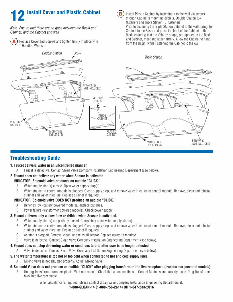
12 Install Cover and Plastic Cabinet
A Replace Cover and Screws and tighten firmly in place with T-Handled Wrench.
B Install Plastic Cabinet by fastening it to the wall via screwsthrough Cabinet’s mounting eyelets. Double Station (6)fasteners and Triple Station (8) fasteners. Prior to fastening the Triple Station Cabinet to the wall, bring theCabinet to the Basin and press the front of the Cabinet to theBasin ensuring that the Velcro® straps, pre-applied to the Basinand Cabinet, meet and attach firmly. Allow the Cabinet to hangfrom the Basin, while Fastening the Cabinet to the wall.
Triple StationDouble Station
PLASTICCABINET
Cover
MOUNTINGEYELETS (8)
P-TRAPS (2)(NOT INCLUDED)
PLASTICCABINET
Cover
MOUNTINGEYELETS (6)
P-TRAPS (2)(NOT INCLUDED)
VELCRO®
STRAPS
INSIDECABINET
When assistance is required, please contact Sloan Valve Company Installation Engineering Department at:1-888-SLOAN-14 (1-888-756-2614) OR 1-847-233-2016
Note: Ensure that there are no gaps between the Basin andCabinet, and the Cabinet and wall.

9
Item Part DescriptionNo. No.1 EW-122 Mounting Bracket (2)2 EW-129 Basin3 ELC-41 Screw, Machine Truss Head 1/4-20 (6)4 EW-135-A Head
† EW-142-A Head with Manual Soap Dispenser5 EW-37 Screw, Truss Head 1/4-20 x 1-1/2” Long (4)6 EW-130-A Cover
‡ EW-138-A Cover with Fill Cap7 EW-115 Cover Attachment Screw8 ‡ ESD-241 Fill Cap for Soap Reservoir9 ‡ ESD-242 Sleeve for Fill Cap10 ‡ ESD-243 Jam Nut for Fill Cap Sleeve11 ETF-725-A Grid Strainer Assembly (2)12 EW-127 Velcro® Strip (Hook)13 EW-105 Plastic Cabinet— MIX-19 Supply Hose (Not Shown)— EW-96 T-Handled Wrench (Not Shown)— EW-128 Velcro® Strip (Loop) (Not Shown)— ‡ ESD-249 Fill Cap Spanner (Not Shown)— EW-98 Light Duty Buffing Pad (Not Shown)— EW-108 General Purpose Buffing Pad (Not Shown)
† EW-141 Spacers (Not Shown)
† Included on models with Soap Dispenser‡ Included on models with Fill Cap
Item Part DescriptionNo. No.A SFP-38 Cable SplitterB SFP-37 Cable ExtensionC SFP-36 Transformer
Parts ListEW-62000 Double Station Top-Level Assembly
7
8
1
13
2
4
6
109
11
5
3
12
4”(102 mm)
51”(1300 mm)
71”(1800 mm)
A B C
EW-62000 Double Station Cables

10
5
10
16146
8
1112
13
23
20
19
17
18
2122
115
7
3
4
29
24
25
Item Part DescriptionNo. No.1 EW-113 Component Mounting Plate, 2 Station2 EW-119 Sensor Housing3 EW-100-A Sensor Base Plate Assembly4 EW-112 Spout Adapter5 EW-140 Washer, 9/16”6 MIX-69 Hex Nut7 EW-14 Nut #8-32 (KEPS)8 ETF-723 Spray Head 0.5 gpm (1.9 Lpm) Vandal Proof9 SFP-41-A Sensor with Range Adjustment Kit10 EW-120 Sensor Backing Piece11 SFP-40 Control Box with Button12 EW-116 Push-In Clip13 SFP-45-A Inlet Adapter Kit
Item Part DescriptionNo. No.14 EW-26 Tube Support 3/8”15 ETF-209 Compression Nut16 ETF-208 Ferrule17 EW-118 Shut-Off Valve18 ETF-61 Male Connector19 EW-19 Compression Tee Fitting 3/8” Tube20 EW-89-1 Tube, 3/8” 1.56” (40 mm) Long21 EW-89-6 Tube, 3/8” 8.19” (208 mm) Long22 EW-89-7 Tube, 3/8” 17.50” (445 mm) Long23 EW-89-10 Tube, 3/8” 24.75” (629 mm) Long24 ETF-198 Tie Wrap25 EW-18 Compression Elbow Fitting 3/8” Tube— ELC-17 Bond Tape (Not Shown)
Parts List
EW-62000 Double Station Electronic Components
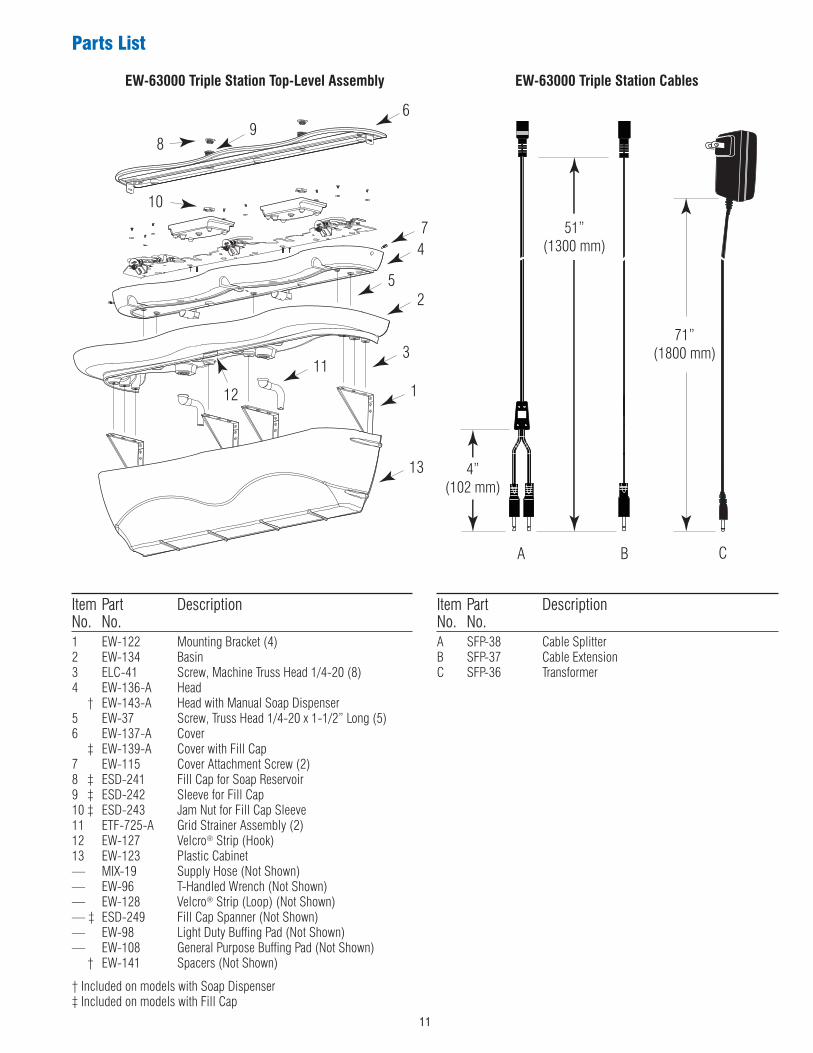
Item Part DescriptionNo. No.1 EW-122 Mounting Bracket (4)2 EW-134 Basin3 ELC-41 Screw, Machine Truss Head 1/4-20 (8)4 EW-136-A Head
† EW-143-A Head with Manual Soap Dispenser5 EW-37 Screw, Truss Head 1/4-20 x 1-1/2” Long (5)6 EW-137-A Cover
‡ EW-139-A Cover with Fill Cap7 EW-115 Cover Attachment Screw (2)8 ‡ ESD-241 Fill Cap for Soap Reservoir9 ‡ ESD-242 Sleeve for Fill Cap10 ‡ ESD-243 Jam Nut for Fill Cap Sleeve11 ETF-725-A Grid Strainer Assembly (2)12 EW-127 Velcro® Strip (Hook)13 EW-123 Plastic Cabinet— MIX-19 Supply Hose (Not Shown)— EW-96 T-Handled Wrench (Not Shown)— EW-128 Velcro® Strip (Loop) (Not Shown)— ‡ ESD-249 Fill Cap Spanner (Not Shown)— EW-98 Light Duty Buffing Pad (Not Shown)— EW-108 General Purpose Buffing Pad (Not Shown)
† EW-141 Spacers (Not Shown)
† Included on models with Soap Dispenser‡ Included on models with Fill Cap
Item Part DescriptionNo. No.A SFP-38 Cable SplitterB SFP-37 Cable ExtensionC SFP-36 Transformer
EW-63000 Triple Station Top-Level Assembly
7
6
4
2
1
13
3
5
8
10
12
11
9
Parts List
4”(102 mm)
51”(1300 mm)
71”(1800 mm)
A B C
EW-63000 Triple Station Cables
11

16
17
9
10
146
8
5
1112
13
25
157
3
42
2019
1822
231
27
21
24
26
The information contained in this document is subject to change without notice.
Parts List
SLOAN VALVE COMPANY • 10500 Seymour Avenue • Franklin Park, IL 60131Phone: 1-800-982-5839 or 1-847-671-4300 • Fax: 1-800-447-8329 or 1-847-671-4380
www.sloanvalve.comPrinted 07-09Copyright © 2009 SLOAN VALVE COMPANY
EW-63000 Triple Station Electronic Components
Item Part DescriptionNo. No.1 EW-117 Component Mounting Plate, 3 Station2 EW-119 Sensor Housing3 EW-100-A Sensor Base Plate Assembly4 EW-112 Spout Adapter5 EW-140 Washer, 9/16”6 MIX-69 Hex Nut7 EW-14 Nut #8-32 (KEPS)8 ETF-723 Spray Head 0.5 gpm (1.9 Lpm) Vandal Proof9 SFP-41-A Sensor with Range Adjustment Kit10 EW-120 Sensor Backing Piece11 SFP-40 Control Box with Button12 EW-116 Push-In Clip13 SFP-45-A Inlet Adapter Kit14 EW-26 Tube Support 3/8”
Item Part DescriptionNo. No.15 ETF-209 Compression Nut16 ETF-208 Ferrule17 EW-118 Shut-Off Valve18 ETF-61 Male Connector19 EW-19 Compression Tee Fitting 3/8” Tube20 EW-89-1 Tube, 3/8” 1.56” (40 mm) Long21 EW-89-5 Tube, 3/8” 6.75” (172 mm) Long22 EW-89-6 Tube, 3/8” 8.19” (208 mm) Long23 EW-89-7 Tube, 3/8” 17.50” (445 mm) Long24 EW-89-9 Tube, 3/8” 25.75” (654 mm) Long25 EW-89-10 Tube, 3/8” 24.75” (629 mm) Long26 EW-18 Compression Elbow Fitting 3/8” Tube27 ETF-198 Tie Wrap— ELC-17 Bond Tape (Not Shown)
When assistance is required, please contact Sloan Valve Company Installation Engineering Department at:
1-888-SLOAN-14 (1-888-756-2614) OR 1-847-233-2016
OperationAs the user’s hands pass under the spray head and enter the beam’s effectiverange, the beam is reflected back into the sensor receiver and activates thesolenoid valve allowing water to flow from the Spray Head. Water will flow untilthe user’s hands are removed from under the Spray Head or until the automatictime out limit setting is reached.