Embed Size (px)
Citation preview
Printed in U.S.A.509 01 3601 00 09--29--08
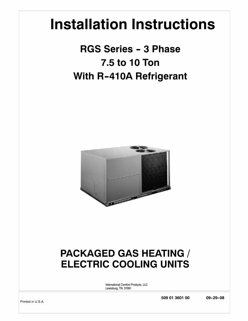
PACKAGED GAS HEATING /ELECTRIC COOLING UNITS
Installation Instructions
RGS Series -- 3 Phase7.5 to 10 Ton
With R--410A Refrigerant
International Comfort Products, LLCLewisburg, TN. 37091

2 509 01 3601 00
FIGURE 1Base Unit Dimensions:
RGS091--121
UNIT J K HRGS091 41---1/4 (1048) 33 (658) 15---7/8 (403)RGS101 49---3/8 (1253) 37---1/4 (377) 23---7/8 (609)RGS121 49---3/8 (1253) 37---1/4 (377) 15---7/8 (403)
3509 01 3601 00
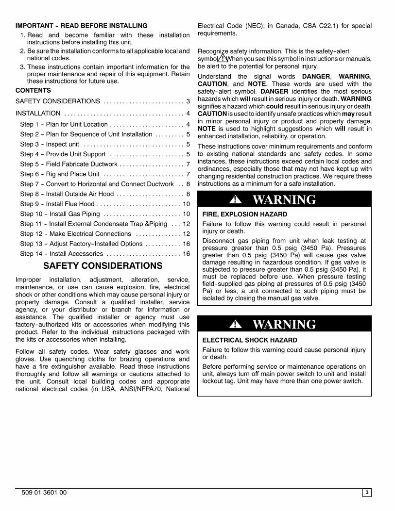
IMPORTANT -- READ BEFORE INSTALLING1. Read and become familiar with these installationinstructions before installing this unit.
2. Be sure the installation conforms to all applicable local andnational codes.
3. These instructions contain important information for theproper maintenance and repair of this equipment. Retainthese instructions for future use.
CONTENTS
SAFETY CONSIDERATIONS 3. . . . . . . . . . . . . . . . . . . . . . . . .
INSTALLATION 4. . . . . . . . . . . . . . . . . . . . . . . . . . . . . . . . . . . . .
Step 1 -- Plan for Unit Location 4. . . . . . . . . . . . . . . . . . . . . . .
Step 2 -- Plan for Sequence of Unit Installation 5. . . . . . . . .
Step 3 -- Inspect unit 5. . . . . . . . . . . . . . . . . . . . . . . . . . . . . . .
Step 4 -- Provide Unit Support 5. . . . . . . . . . . . . . . . . . . . . . .
Step 5 -- Field Fabricate Ductwork 7. . . . . . . . . . . . . . . . . . . .
Step 6 -- Rig and Place Unit 7. . . . . . . . . . . . . . . . . . . . . . . . .
Step 7 -- Convert to Horizontal and Connect Ductwork 8. .
Step 8 -- Install Outside Air Hood 8. . . . . . . . . . . . . . . . . . . . .
Step 9 -- Install Flue Hood 10. . . . . . . . . . . . . . . . . . . . . . . . . .
Step 10 -- Install Gas Piping 10. . . . . . . . . . . . . . . . . . . . . . . .
Step 11 -- Install External Condensate Trap &Piping 12. . .
Step 12 -- Make Electrical Connections 12. . . . . . . . . . . . . .
Step 13 -- Adjust Factory--Installed Options 16. . . . . . . . . . .
Step 14 -- Install Accessories 16. . . . . . . . . . . . . . . . . . . . . . .
SAFETY CONSIDERATIONSImproper installation, adjustment, alteration, service,maintenance, or use can cause explosion, fire, electricalshock or other conditions which may cause personal injury orproperty damage. Consult a qualified installer, serviceagency, or your distributor or branch for information orassistance. The qualified installer or agency must usefactory--authorized kits or accessories when modifying thisproduct. Refer to the individual instructions packaged withthe kits or accessories when installing.
Follow all safety codes. Wear safety glasses and workgloves. Use quenching cloths for brazing operations andhave a fire extinguisher available. Read these instructionsthoroughly and follow all warnings or cautions attached tothe unit. Consult local building codes and appropriatenational electrical codes (in USA, ANSI/NFPA70, National
Electrical Code (NEC); in Canada, CSA C22.1) for specialrequirements.
Recognize safety information. This is the safety--alertsymbol .Whenyousee this symbol in instructionsormanuals,be alert to the potential for personal injury.
Understand the signal words DANGER, WARNING,CAUTION, and NOTE. These words are used with thesafety--alert symbol. DANGER identifies the most serioushazards whichwill result in serious injury or death.WARNINGsignifies a hazard which could result in serious injury or death.CAUTION is used to identify unsafe practiceswhichmay resultin minor personal injury or product and property damage.NOTE is used to highlight suggestions which will result inenhanced installation, reliability, or operation.
These instructions cover minimum requirements and conformto existing national standards and safety codes. In someinstances, these instructions exceed certain local codes andordinances, especially those that may not have kept up withchanging residential construction practices. We require theseinstructions as a minimum for a safe installation.
FIRE, EXPLOSION HAZARDFailure to follow this warning could result in personalinjury or death.Disconnect gas piping from unit when leak testing atpressure greater than 0.5 psig (3450 Pa). Pressuresgreater than 0.5 psig (3450 Pa) will cause gas valvedamage resulting in hazardous condition. If gas valve issubjected to pressure greater than 0.5 psig (3450 Pa), itmust be replaced before use. When pressure testingfield--supplied gas piping at pressures of 0.5 psig (3450Pa) or less, a unit connected to such piping must beisolated by closing the manual gas valve.
! WARNING
ELECTRICAL SHOCK HAZARDFailure to follow this warning could cause personal injuryor death.Before performing service or maintenance operations onunit, always turn off main power switch to unit and installlockout tag. Unit may have more than one power switch.
! WARNING
!

Unit Dimansional Drawing (Cont.)Figure 1
4 509 01 3601 00
UNITStd. UnitWeight
CornerWeight A
CornerWeight B
CornerWeight C
CornerWeight D
Center of GravityX Y Z
LB KG LB KG LB KG LB KG LB KG IN MM IN MM IN MMRGS091 810 367 171 78 164 74 233 106 242 110 41--7/8 1064 33--7/8 860 20--1/4 514RGS101 910 413 193 88 181 72 260 118 276 125 41--3/8 1051 22--7/8 581 22--7/8 581RGS121 965 438 207 94 204 93 275 125 279 127 42--3/8 1076 24--1/8 613 24--1/8 613
INSTALLATION
UNIT OPERATION AND SAFETY HAZARDFailure to follow this warning could cause personal injury,death and/or equipment damage.R--410A refrigerant systems operate at higher pressuresthan standard R--22 systems. Do not use R--22 serviceequipment or components on R--410A refrigerantequipment.
! WARNING
Jobsite SurveyComplete the following checks before installation.
1. Consult local building codes and the NEC (NationalElectrical Code) ANSI/NFPA 70 for special installationrequirements.
2. Determine unit location (from project plans) or select unitlocation.
3. Check for possible overhead obstructions which mayinterfere with unit lifting or rigging.
Step 1 — Plan for Unit Location
Select a location for the unit and its support system (curb orother) that provides for the minimum clearances required forsafety. This includes the clearance to combustible surfaces,unit performance and service access below, around andabove unit as specified in unit drawings. See Fig. 2.
FIGURE 2 Service Clearance Dimansional Drawing
18” (457)
42" (1067)
18" (457)42" (1067)
1
Required bottom condensate drain connection.Otherwise, 36” (914mm) for condensate connection.
1
NOTE:Consider also the effect of adjacent units.
Be sure that unit is installed such that snow will not block thecombustion intake or flue outlet.
Unit may be installed directly on wood flooring or on Class A,B, or C roof--covering material when roof curb is used.
Do not install unit in an indoor location. Do not locate airinlets near exhaust vents or other sources of contaminatedair. For proper unit operation, adequate combustion andventilation air must be provided in accordance with Section5.3 (Air for Combustion and Ventilation) of the National FuelGas Code, ANSI Z223.1 (American National StandardsInstitute) and NFPA (National Fire Protection Association) 54TIA--54--84--1. In Canada, installation must be in accordancewith the CAN1--B149 installation codes for gas burningappliances.
5509 01 3601 00
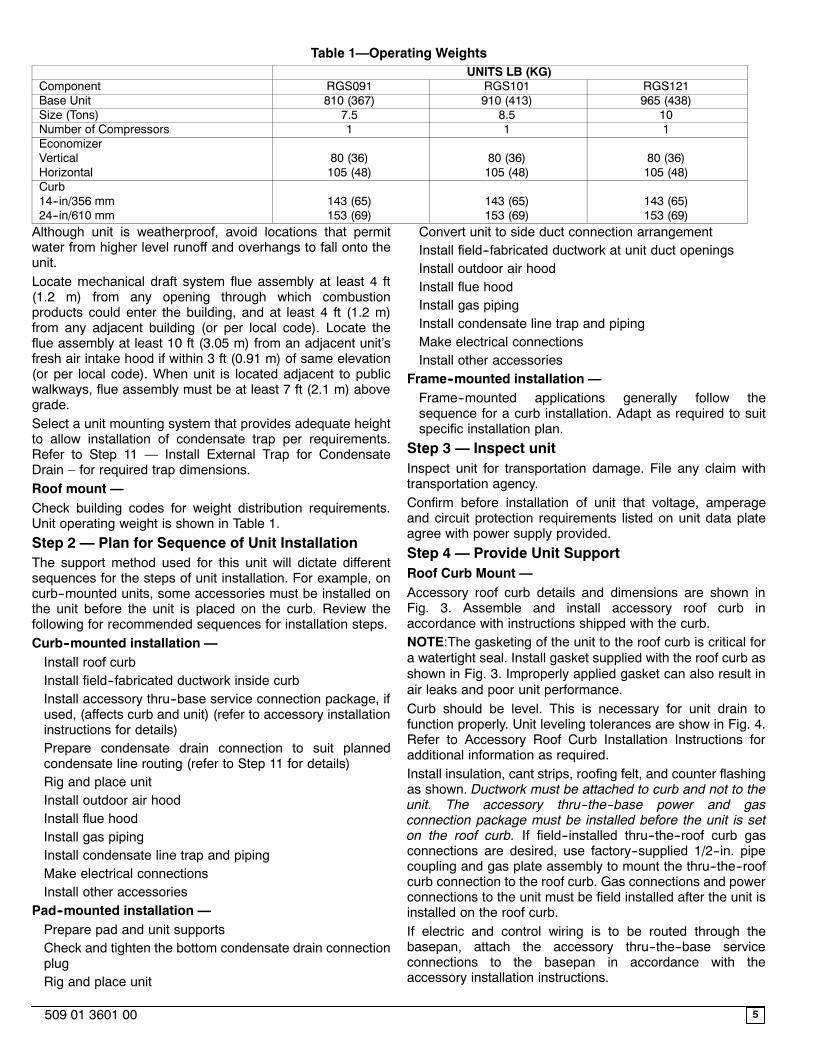
Table 1—Operating WeightsUNITS LB (KG)
Component RGS091 RGS101 RGS121Base Unit 810 (367) 910 (413) 965 (438)Size (Tons) 7.5 8.5 10Number of Compressors 1 1 1EconomizerVertical 80 (36) 80 (36) 80 (36)Horizontal 105 (48) 105 (48) 105 (48)Curb14--in/356 mm 143 (65) 143 (65) 143 (65)24--in/610 mm 153 (69) 153 (69) 153 (69)Although unit is weatherproof, avoid locations that permitwater from higher level runoff and overhangs to fall onto theunit.Locate mechanical draft system flue assembly at least 4 ft(1.2 m) from any opening through which combustionproducts could enter the building, and at least 4 ft (1.2 m)from any adjacent building (or per local code). Locate theflue assembly at least 10 ft (3.05 m) from an adjacent unit’sfresh air intake hood if within 3 ft (0.91 m) of same elevation(or per local code). When unit is located adjacent to publicwalkways, flue assembly must be at least 7 ft (2.1 m) abovegrade.Select a unit mounting system that provides adequate heightto allow installation of condensate trap per requirements.Refer to Step 11 — Install External Trap for CondensateDrain – for required trap dimensions.Roof mount —Check building codes for weight distribution requirements.Unit operating weight is shown in Table 1.Step 2 — Plan for Sequence of Unit InstallationThe support method used for this unit will dictate differentsequences for the steps of unit installation. For example, oncurb--mounted units, some accessories must be installed onthe unit before the unit is placed on the curb. Review thefollowing for recommended sequences for installation steps.Curb--mounted installation —Install roof curbInstall field--fabricated ductwork inside curbInstall accessory thru--base service connection package, ifused, (affects curb and unit) (refer to accessory installationinstructions for details)Prepare condensate drain connection to suit plannedcondensate line routing (refer to Step 11 for details)Rig and place unitInstall outdoor air hoodInstall flue hoodInstall gas pipingInstall condensate line trap and pipingMake electrical connectionsInstall other accessories
Pad--mounted installation —Prepare pad and unit supportsCheck and tighten the bottom condensate drain connectionplugRig and place unit
Convert unit to side duct connection arrangementInstall field--fabricated ductwork at unit duct openingsInstall outdoor air hoodInstall flue hoodInstall gas pipingInstall condensate line trap and pipingMake electrical connectionsInstall other accessories
Frame--mounted installation —Frame--mounted applications generally follow thesequence for a curb installation. Adapt as required to suitspecific installation plan.
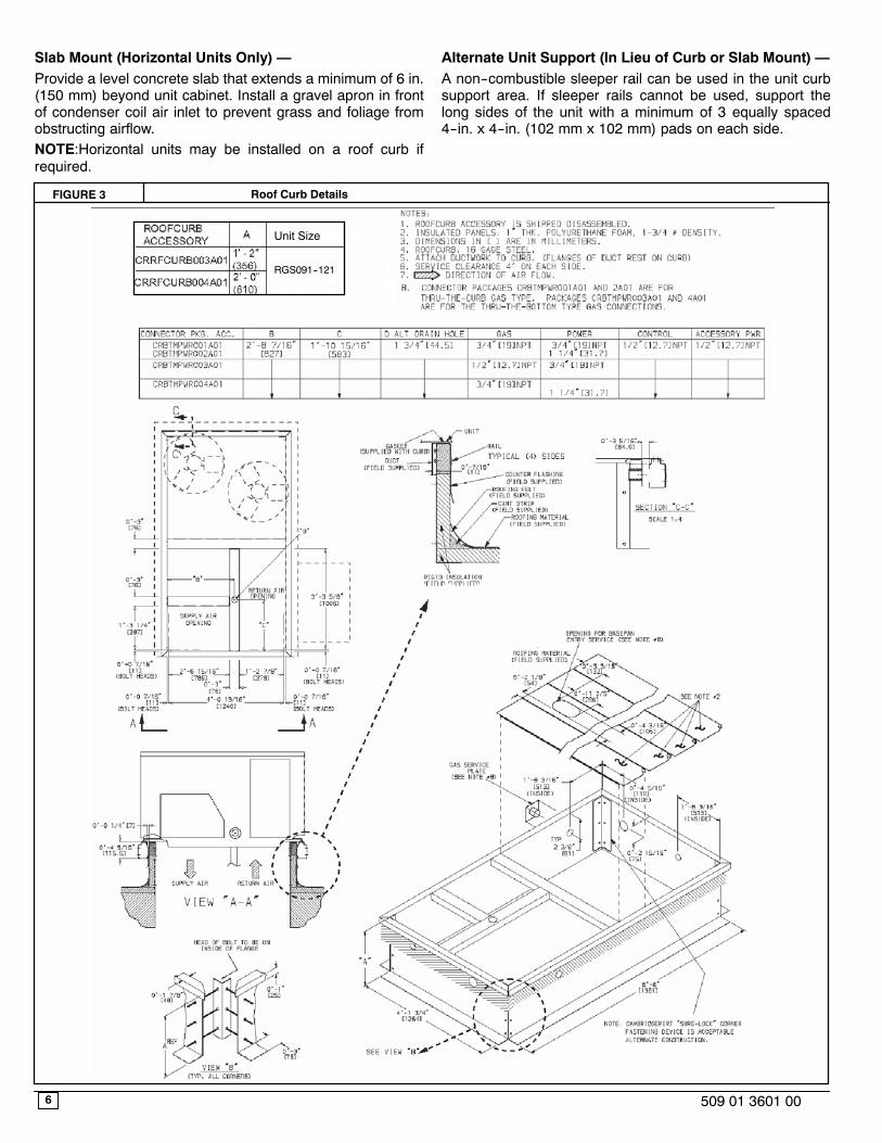
Step 3 — Inspect unitInspect unit for transportation damage. File any claim withtransportation agency.Confirm before installation of unit that voltage, amperageand circuit protection requirements listed on unit data plateagree with power supply provided.Step 4 — Provide Unit SupportRoof Curb Mount —Accessory roof curb details and dimensions are shown inFig. 3. Assemble and install accessory roof curb inaccordance with instructions shipped with the curb.NOTE:The gasketing of the unit to the roof curb is critical fora watertight seal. Install gasket supplied with the roof curb asshown in Fig. 3. Improperly applied gasket can also result inair leaks and poor unit performance.Curb should be level. This is necessary for unit drain tofunction properly. Unit leveling tolerances are show in Fig. 4.Refer to Accessory Roof Curb Installation Instructions foradditional information as required.Install insulation, cant strips, roofing felt, and counter flashingas shown. Ductwork must be attached to curb and not to theunit. The accessory thru--the--base power and gasconnection package must be installed before the unit is seton the roof curb. If field--installed thru--the--roof curb gasconnections are desired, use factory--supplied 1/2--in. pipecoupling and gas plate assembly to mount the thru--the--roofcurb connection to the roof curb. Gas connections and powerconnections to the unit must be field installed after the unit isinstalled on the roof curb.If electric and control wiring is to be routed through thebasepan, attach the accessory thru--the--base serviceconnections to the basepan in accordance with theaccessory installation instructions.
6 509 01 3601 00
Slab Mount (Horizontal Units Only) —Provide a level concrete slab that extends a minimum of 6 in.(150 mm) beyond unit cabinet. Install a gravel apron in frontof condenser coil air inlet to prevent grass and foliage fromobstructing airflow.NOTE:Horizontal units may be installed on a roof curb ifrequired.
Alternate Unit Support (In Lieu of Curb or Slab Mount) —A non--combustible sleeper rail can be used in the unit curbsupport area. If sleeper rails cannot be used, support thelong sides of the unit with a minimum of 3 equally spaced4--in. x 4--in. (102 mm x 102 mm) pads on each side.
FIGURE 3 Roof Curb Details
Unit Size
RGS091--121

FIGURE 5 Rigging Details
NOTES:1. Dimensions in ( ) are in millimeters.2. Hook rigging shackles through holes in base rail, as shown in
detail “A.” Holes in base rails are centered around the unit centerof gravity. Use wooden top skid when rigging to prevent riggingstraps from damaging unit.
3. Unit weights do not include economizer. See Table 1 for econo--mizer weights.
7509 01 3601 00
FIGURE 4 Unit Leveling Tolerances
MAXIMUM ALLOWABLE
A--B B--C A--C0.5”(13) 1.0” (25) 1.0” (25)
Step 5 — Field Fabricate Ductwork
Cabinet return-air static pressure (a negative condition) shallnot exceed 0.35 in. wg (87 Pa) with economizer or 0.45 in.wg (112 Pa) without economizer.
For vertical ducted applications, secure all ducts to roof curband building structure. Do not connect ductwork to unit.
Insulate and weatherproof all external ductwork, joints, androof openings with counter flashing and mastic inaccordance with applicable codes.
Ducts passing through unconditioned spaces must beinsulated and covered with a vapor barrier.
If a plenum return is used on a vertical unit, the return shouldbe ducted through the roof deck to comply with applicablefire codes.
A minimum clearance is not required around ductwork.
Step 6 — Rig and Place Unit
Keep unit upright and do not drop. Spreader bars are notrequired if top crating is left on unit. Rollers may be used tomove unit across a roof. Level by using unit frame as areference. See Table 1 and Fig. 5 for additional information.
Lifting holes are provided in base rails as shown in Fig. 5.Refer to rigging instructions on unit.
UNIT DAMAGE HAZARDFailure to follow this caution may result in equipmentdamage.All panels must be in place when rigging. Unit is notdesigned for handling by fork truck.
CAUTION!
Before setting the unit onto the curb, recheck gasketing oncurb.
UNITMAX WEIGHT
DIMENSIONSA B C
LB KG IN MM IN MM IN MMRGS091 860 390 88.18 2240 42 1067 41.14 1045RGS101 960 435 88.18 2240 42 1067 49.38 1254RGS121 1015 460 88.18 2240 42 1067 49.38 1254
8 509 01 3601 00
Positioning on Curb —
Position unit on roof curb so that the following clearances aremaintained: 1/4 in. (6.4 mm) clearance between the roof curband the base rail inside the front and rear, 0.0 in. clearancebetween the roof curb and the base rail inside on the ductend of the unit. This will result in the distance between theroof curb and the base rail inside on the condenser end ofthe unit being approximately equal to Fig. 3, section C--C.
Although unit is weatherproof, guard against water fromhigher level runoff and overhangs.
UNIT DAMAGE HAZARDFailure to follow this caution may result inequipment damage.All panels must be in place when rigging. Unit isnot designed for handling by fork truck.
CAUTION!
Flue vent discharge must have a minimum horizontalclearance of 4 ft (1220 mm) from electric and gas meters,gas regulators, and gas relief equipment. Minimum distancebetween unit and other electrically live parts is 48 inches(1220 mm).
Flue gas can deteriorate building materials. Orient unit suchthat flue gas will not affect building materials. Locatemechanical draft system flue assembly at least 48 in. (1220mm) from an adjacent building or combustible material.
NOTE:Installation of accessory flue discharge deflector kitwill reduce the minimum clearance to combustible material to18 in. (460 mm).
After unit is in position, remove rigging skids and shippingmaterials.
Step 7 — Convert to Horizontal and ConnectDuctwork (when required)
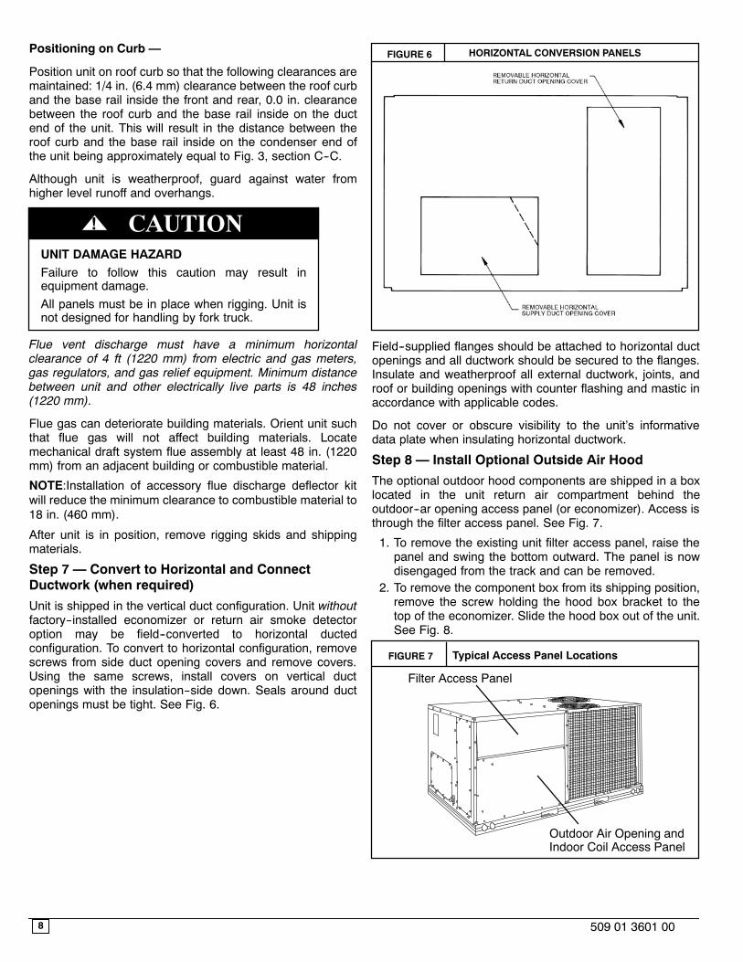
Unit is shipped in the vertical duct configuration. Unit withoutfactory--installed economizer or return air smoke detectoroption may be field--converted to horizontal ductedconfiguration. To convert to horizontal configuration, removescrews from side duct opening covers and remove covers.Using the same screws, install covers on vertical ductopenings with the insulation--side down. Seals around ductopenings must be tight. See Fig. 6.
FIGURE 6 HORIZONTAL CONVERSION PANELS
Field--supplied flanges should be attached to horizontal ductopenings and all ductwork should be secured to the flanges.Insulate and weatherproof all external ductwork, joints, androof or building openings with counter flashing and mastic inaccordance with applicable codes.
Do not cover or obscure visibility to the unit’s informativedata plate when insulating horizontal ductwork.
Step 8 — Install Optional Outside Air Hood
The optional outdoor hood components are shipped in a boxlocated in the unit return air compartment behind theoutdoor--ar opening access panel (or economizer). Access isthrough the filter access panel. See Fig. 7.
1. To remove the existing unit filter access panel, raise thepanel and swing the bottom outward. The panel is nowdisengaged from the track and can be removed.
2. To remove the component box from its shipping position,remove the screw holding the hood box bracket to thetop of the economizer. Slide the hood box out of the unit.See Fig. 8.
FIGURE 7 Typical Access Panel Locations
Filter Access Panel
Outdoor Air Opening andIndoor Coil Access Panel
9509 01 3601 00
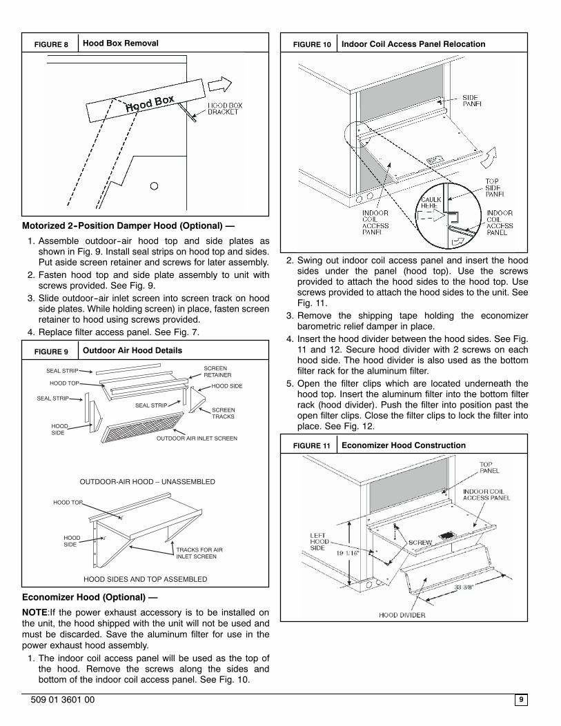
FIGURE 8 Hood Box Removal
Motorized 2--Position Damper Hood (Optional) —
1. Assemble outdoor--air hood top and side plates asshown in Fig. 9. Install seal strips on hood top and sides.Put aside screen retainer and screws for later assembly.
2. Fasten hood top and side plate assembly to unit withscrews provided. See Fig. 9.
3. Slide outdoor--air inlet screen into screen track on hoodside plates. While holding screen) in place, fasten screenretainer to hood using screws provided.
4. Replace filter access panel. See Fig. 7.
FIGURE 9 Outdoor Air Hood Details
SEAL STRIP
HOOD TOP
SEAL STRIP
HOOD SIDE
SCREEN RETAINER
HOOD SIDE
SCREEN TRACKS
OUTDOOR AIR INLET SCREEN
SEAL STRIP
OUTDOOR-AIR HOOD – UNASSEMBLED
HOOD SIDES AND TOP ASSEMBLED
TRACKS FOR AIR INLET SCREEN
HOOD SIDE
HOOD TOP
Economizer Hood (Optional) —
NOTE:If the power exhaust accessory is to be installed onthe unit, the hood shipped with the unit will not be used andmust be discarded. Save the aluminum filter for use in thepower exhaust hood assembly.1. The indoor coil access panel will be used as the top ofthe hood. Remove the screws along the sides andbottom of the indoor coil access panel. See Fig. 10.
FIGURE 10 Indoor Coil Access Panel Relocation
2. Swing out indoor coil access panel and insert the hoodsides under the panel (hood top). Use the screwsprovided to attach the hood sides to the hood top. Usescrews provided to attach the hood sides to the unit. SeeFig. 11.
3. Remove the shipping tape holding the economizerbarometric relief damper in place.
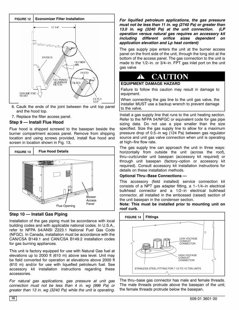
4. Insert the hood divider between the hood sides. See Fig.11 and 12. Secure hood divider with 2 screws on eachhood side. The hood divider is also used as the bottomfilter rack for the aluminum filter.
5. Open the filter clips which are located underneath thehood top. Insert the aluminum filter into the bottom filterrack (hood divider). Push the filter into position past theopen filter clips. Close the filter clips to lock the filter intoplace. See Fig. 12.
FIGURE 11 Economizer Hood Construction
10 509 01 3601 00
FIGURE 12 Economizer Filter Installation
6. Caulk the ends of the joint between the unit top paneland the hood top.
7. Replace the filter access panel.Step 9 — Install Flue Hood
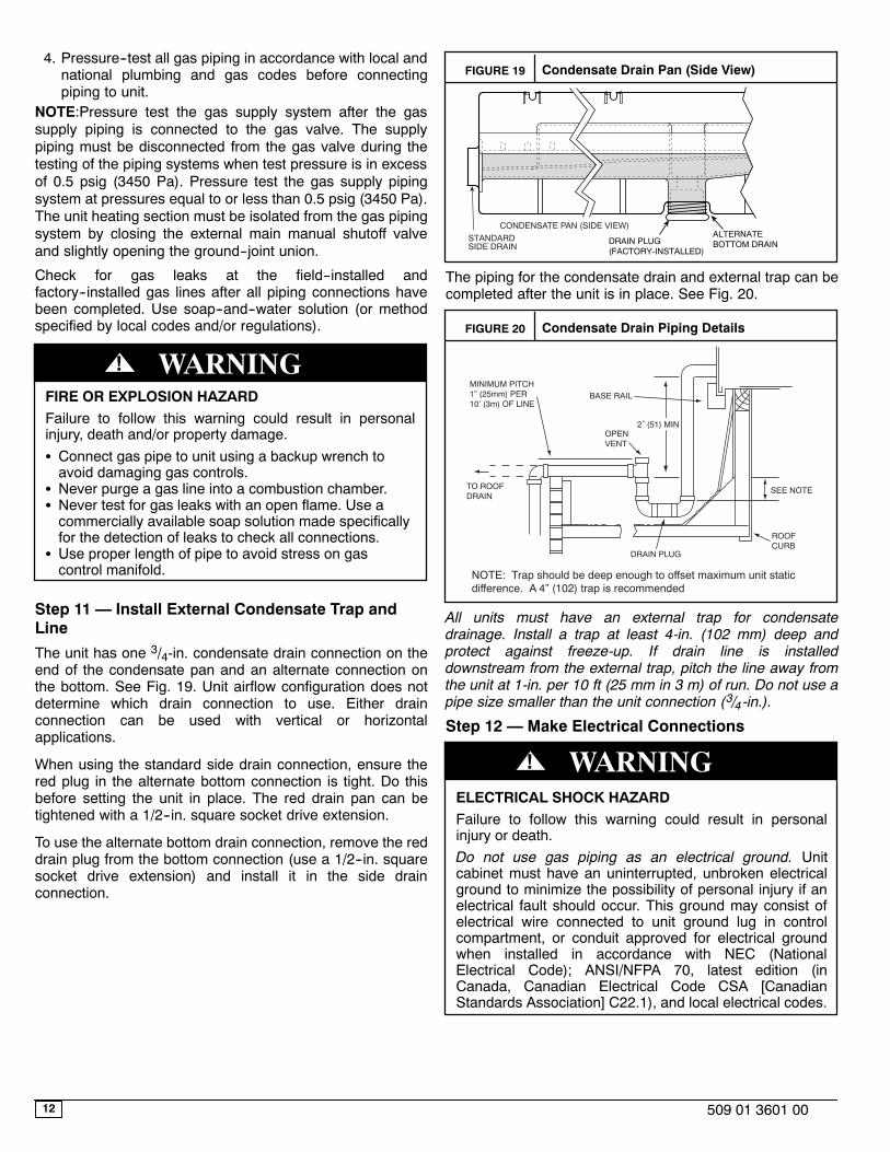
Flue hood is shipped screwed to the basepan beside theburner compartment access panel. Remove from shippinglocation and using screws provided, install flue hood andscreen in location shown in Fig. 13.
FIGURE 13 Flue Hood Details
Flue Opening
BlowerAccessPanel
Step 10 — Install Gas Piping
Installation of the gas piping must be accordance with localbuilding codes and with applicable national codes. In U.S.A.,refer to NFPA 54/ANSI Z223.1 National Fuel Gas Code(NFGC). In Canada, installation must be accordance with theCAN/CSA B149.1 and CAN/CSA B149.2 installation codesfor gas burning appliances.
This unit is factory equipped for use with Natural Gas fuel atelevations up to 2000 ft (610 m) above sea level. Unit maybe field converted for operation at elevations above 2000 ft(610 m) and/or for use with liquefied petroleum fuel. Seeaccessory kit installation instructions regarding theseaccessories.
For natural gas applications, gas pressure at unit gasconnection must not be less than 4 in. wg (996 Pa) orgreater than 13 in. wg (3240 Pa) while the unit is operating.
For liquified petroleum applications, the gas pressuremust not be less than 11 in. wg (2740 Pa) or greater than13.0 in. wg (3240 Pa) at the unit connection. (LPoperation versus natural gas requires an accessory kitincluding different orifice sizes dependent onapplication elevation and Lp heat content)
The gas supply pipe enters the unit at the burner accesspanel on the front side of the unit, through the long slot at thebottom of the access panel. The gas connection to the unit ismade to the 1/2--in. or 3/4--in. FPT gas inlet port on the unitgas valve
EQUIPMENT DAMAGE HAZARDFailure to follow this caution may result in damage toequipment.When connecting the gas line to the unit gas valve, theinstaller MUST use a backup wrench to prevent damageto the valve.
CAUTION!
Install a gas supply line that runs to the unit heating section.Refer to the NFPA 54/NFGC or equivalent code for gas pipesizing data. Do not use a pipe smaller than the sizespecified. Size the gas supply line to allow for a maximumpressure drop of 0.5--in wg (124 Pa) between gas regulatorsource and unit gas valve connection when unit is operatingat high--fire flow rate.The gas supply line can approach the unit in three ways:horizontally from outside the unit (across the roof),thru--curb/under unit basepan (accessory kit required) orthrough unit basepan (factory--option or accessory kitrequired). Consult accessory kit installation instructions fordetails on these installation methods.Optional Thru--Base Connections —This accessory (field installed) service connection kitconsists of a NPT gas adapter fitting, a 1--1/4--in electricalbulkhead connector and a 1/2--in electrical bulkheadconnector, all installed in the embossed (raised) section ofthe unit basepan in the condenser section.Note: This must be installed prior to mounting unit onroof curb.
FIGURE 14 Fittings
LOW VOLTAGECONDUITCONNECTOR
STAINLESS STEEL FITTING FOR 7 1/2 TO 10 TON UNITS
HIGH VOLTAGECONDUITCONNECTOR
The thru--base gas connector has male and female threads.The male threads protrude above the basepan of the unit;the female threads protrude below the basepan.

11509 01 3601 00
Check tightness of connector lock nuts before connectinggas piping.
Install a 3/4--in NPT street elbow on the thru--base gas fitting.Attach an appropriate size pipe nipple with minimum lengthof 19--in (483 mm) (field--supplied) to the street elbow andextend it through the access panel at the gas supportbracket. See Fig. 15.
FIGURE 15 Gas Line Piping for 7--1/2 to 10 Ton Units
EMBOSSMENT STAINLESS STEEL FITTINGFOR 7.5 - 10 TON UNITS
SUPPORTBRACKET
Other hardware required to complete the installation of thegas supply line will include a manual shutoff valve, asediment trap (drip leg) and a ground--joint union. A pressureregulator valve may also be required (to convert gaspressure from pounds to inches of pressure). The manualshutoff valve must be located within 6--ft (1.83 m) of the unit.The union, located in the final leg entering the unit, must belocated at least 9--in (230 mm) away from the access panelto permit the panel to be removed for service. If a regulatorvalve is installed, it must be located a minimum of 4--ft (1220mm) away from the unit’s flue outlet. Some municipal codesrequire that the manual shutoff valve be located upstream ofthe sediment trap. See Figures 16 and 17 for typical pipingarrangements for gas piping that has been routed throughthe sidewall of the curb. See Fig. 18 for typical pipingarrangement when thru--base is used. Ensure that all pipingdoes not block access to the unit’s main control box or limitthe required working space in front of the control box.
FIGURE 16 Gas Piping
9” (229mm) min
Union
Shut OffValve
DripLeg
Thru-Curb Adapter
Unit Base Rail
FIGURE 17 Gas Piping
DripLeg
Shut OffValve
Union
Thru-Curb Adapter
BurnerAccessPanel
9” (229mm) min
Unit Base Rail
FIGURE 18 Gas Piping Thru--Base Connections
When installing the gas supply line, observe local codespertaining to gas pipe installations. Refer to the NFPA54/ANSI Z223.1 NFGC latest edition (in Canada, CAN/CSAB149.1). In the absence of local building codes, adhere tothe following pertinent recommendations:
1. Avoid low spots in long runs of pipe. Grade all pipe1/4--in. in every 15 ft (7 mm in every 5 m) to preventtraps. Grade all horizontal runs downward to risers. Userisers to connect to heating section and to meter.
2. Protect all segments of piping system against physicaland thermal damage. Support all piping with appropriatestraps, hangers, etc. Use a minimum of one hangerevery 6 ft (1.8 m). For pipe sizes larger than 1/2--in.,follow recommendations of national codes.
3. Apply joint compound (pipe dope) sparingly and only tomale threads of joint when making pipe connections.Use only pipe dope that is resistant to action of liquefiedpetroleum gases as specified by local and/or nationalcodes. If using PTFE (Teflon) tape, ensure the material isDouble Density type and is labeled for use on gas lines.Apply tape per manufacturer’s instructions.
12 509 01 3601 00
4. Pressure--test all gas piping in accordance with local andnational plumbing and gas codes before connectingpiping to unit.
NOTE:Pressure test the gas supply system after the gassupply piping is connected to the gas valve. The supplypiping must be disconnected from the gas valve during thetesting of the piping systems when test pressure is in excessof 0.5 psig (3450 Pa). Pressure test the gas supply pipingsystem at pressures equal to or less than 0.5 psig (3450 Pa).The unit heating section must be isolated from the gas pipingsystem by closing the external main manual shutoff valveand slightly opening the ground--joint union.
Check for gas leaks at the field--installed andfactory--installed gas lines after all piping connections havebeen completed. Use soap--and--water solution (or methodspecified by local codes and/or regulations).
FIRE OR EXPLOSION HAZARDFailure to follow this warning could result in personalinjury, death and/or property damage.S Connect gas pipe to unit using a backup wrench toavoid damaging gas controls.
S Never purge a gas line into a combustion chamber.S Never test for gas leaks with an open flame. Use acommercially available soap solution made specificallyfor the detection of leaks to check all connections.
S Use proper length of pipe to avoid stress on gascontrol manifold.
! WARNING
Step 11 — Install External Condensate Trap andLine
The unit has one 3/4-in. condensate drain connection on theend of the condensate pan and an alternate connection onthe bottom. See Fig. 19. Unit airflow configuration does notdetermine which drain connection to use. Either drainconnection can be used with vertical or horizontalapplications.
When using the standard side drain connection, ensure thered plug in the alternate bottom connection is tight. Do thisbefore setting the unit in place. The red drain pan can betightened with a 1/2--in. square socket drive extension.
To use the alternate bottom drain connection, remove the reddrain plug from the bottom connection (use a 1/2--in. squaresocket drive extension) and install it in the side drainconnection.
FIGURE 19 Condensate Drain Pan (Side View)
DRAIN(FACTORY-INSTALLED)
PLUG
CONDENSATE PAN (SIDE VIEW)
STANDARDSIDE DRAIN
ALTERNATEBOTTOM DRAIN
The piping for the condensate drain and external trap can becompleted after the unit is in place. See Fig. 20.
FIGURE 20 Condensate Drain Piping Details
NOTE: Trap should be deep enough to offset maximum unit staticdifference. A 4” (102) trap is recommended.
MINIMUM PITCH1” (25mm) PER10’ (3m) OF LINE
BASE RAIL
OPENVENT
TO ROOFDRAIN
DRAIN PLUG
ROOFCURB
SEE NOTE
2˝ (51) MIN
All units must have an external trap for condensatedrainage. Install a trap at least 4-in. (102 mm) deep andprotect against freeze-up. If drain line is installeddownstream from the external trap, pitch the line away fromthe unit at 1-in. per 10 ft (25 mm in 3 m) of run. Do not use apipe size smaller than the unit connection (3/4 -in.).
Step 12 — Make Electrical Connections
ELECTRICAL SHOCK HAZARDFailure to follow this warning could result in personalinjury or death.Do not use gas piping as an electrical ground. Unitcabinet must have an uninterrupted, unbroken electricalground to minimize the possibility of personal injury if anelectrical fault should occur. This ground may consist ofelectrical wire connected to unit ground lug in controlcompartment, or conduit approved for electrical groundwhen installed in accordance with NEC (NationalElectrical Code); ANSI/NFPA 70, latest edition (inCanada, Canadian Electrical Code CSA [CanadianStandards Association] C22.1), and local electrical codes.
! WARNING
13509 01 3601 00
Field Power Supply —
All units except 208/230-v units are factory wired for thevoltage shown on the nameplate. If the 208/230-v unit is tobe connected to a 208-v power supply, the controltransformer must be rewired by moving the black wire withthe 1/4 -in. female spade connector from the 230--vconnection and moving it to the 200-v 1/4 -in. male terminalon the primary side of the transformer. Refer to unit labeldiagram for additional information. Field power wires will beconnected line--side pressure lugs on the power terminalblock or at factory--installed option non--fused disconnect.
Field power wires are connected to the unit at line--sidepressure lugs on compressor contactor C and indoor fancontactor IFC (see wiring diagram label for control boxcomponent arrangement) or at factory--installed optionnon--fused disconnect switch. Max wire size is #2 AWG(copper only).
NOTE:TEST LEADS -- Unit may be equipped with shortleads (pigtails) on the field line connection points oncontactor C or optional disconnect switch. These leads arefor factory run--test purposes only; remove and discardbefore connecting field power wires to unit connection points.Make field power connections directly to line connectionpressure lugs only.
Units Without Factory--Installed Disconnect —
When installing units, provide a disconnect switch per NEC(National Electrical Code) of adequate size. Disconnectsizing data is provided on the unit informative plate. Locateon unit cabinet or within sight of the unit per national or localcodes. Do not cover unit informative plate if mounting thedisconnect on the unit cabinet.
Units with Factory--Installed Disconnect —
The factory--installed option disconnect switch is located in aweatherproof enclosure located under the main control box.The manual switch handle is accessible through an openingin the access panel.
All units --
All field wiring must comply with NEC and all local codes.Size wire based on MCA (Minimum Circuit Amps) on the unitinformative plate. See Fig. 21 for power wiring connectionsto the unit power terminal block and equipment ground.Maximum wire size is #2 ga AWG per pole.
Provide a ground--fault and short--circuit over--currentprotection device (fuse or breaker) per NEC Article 440 (orlocal codes). Refer to unit informative data plate for MOCP(Maximum Over--current Protection) device size.
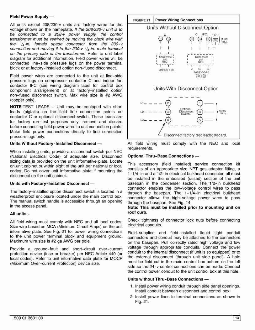
FIGURE 21 Power Wiring Connections
Disconnectper
NEC
Disconnectper
NEC
208/230-1-60
11 13 11 13 13
L1 L2 L3
TB
C C IFC or(1-ph IFM)
208/230-3-60460-3-60575-3-60
Units Without Disconnect Option
Units With Disconnect Option
2
4
6
1
3
5
L1
L2
L3
OptionalDisconnect
Switch
Disconnect factory test leads; discard.
FactoryWiring
All field wiring must comply with the NEC and localrequirements.
Optional Thru--Base Connections —
This accessory (field installed) service connection kitconsists of an appropriate size NPT gas adapter fitting, a1--1/4--in and a 1/2--in electrical bulkhead connector, all mustbe installed in the embossed (raised) section of the unitbasepan in the condenser section. The 1/2--in bulkheadconnector enables the low--voltage control wires to passthrough the basepan. The 1--1/4--in electrical bulkheadconnector allows the high--voltage power wires to passthrough the basepan. See Fig. 14.Note: This must be installed prior to mounting unit onroof curb.
Check tightness of connector lock nuts before connectingelectrical conduits.
Field--supplied and field--installed liquid tight conduitconnectors and conduit may be attached to the connectorson the basepan. Pull correctly rated high voltage and lowvoltage through appropriate conduits. Connect the powerconduit to the internal disconnect (if unit is so equipped) or tothe external disconnect (through unit side panel). A holemust be field cut in the main control box bottom on the leftside so the 24--v control connections can be made. Connectthe control power conduit to the unit control box at this hole.
Units without Thru--Base Connections —
1. Install power wiring conduit through side panel openings.Install conduit between disconnect and control box.
2. Install power lines to terminal connections as shown inFig. 21.
14 509 01 3601 00
Voltage to compressor terminals during operation must bewithin voltage range indicated on unit nameplate. See Table2. On 3--phase units, voltages between phases must bebalanced within 2% and the current within 10%. Use theformula shown in the legend for Table 2, Note 2 to determinethe percent of voltage imbalance. Operation on improper linevoltage or excessive phase imbalance constitutes abuse andmay cause damage to electrical components. Suchoperation would invalidate any applicable Bryant warranty.
Field Control Wiring —
The RGS unit requires an external temperature controldevice. This device typically applied with a commercialthermostat (field--supplied) with both occupied andunoccupied setpoints at a minimum.
Thermostat —
Install an approved accessory commercial thermostataccording to installation instructions included with theaccessory. For complete economizer function, select atwo--stage cooling thermostat. Locate the thermostataccessory on a solid wall in the conditioned space to senseaverage temperature in accordance with the thermostatinstallation instructions.
If the thermostat contains a logic circuit requiring 24--vpower, use a thermostat cable or equivalent single leads ofdifferent colors with minimum of seven leads. If thethermostat does not require a 24--v source (no “C”connection required), use a thermostat cable or equivalentwith minimum of six leads. Check the thermostat installationinstructions for additional features which might requireadditional conductors in the cable.
For wire runs up to 50 ft. (15 m), use no. 18 AWG (AmericanWire Gage) insulated wire (35_C minimum). For 50 to 75 ft.(15 to 23 m), use no. 16 AWG insulated wire (35_Cminimum). For over 75 ft. (23 m), use no. 14 AWG insulatedwire (35_C minimum). All wire sizes larger than no. 18 AWGcannot be directly connected to the thermostat and willrequire a junction box and splice at the thermostat.
Unit without thru--base connection kit —
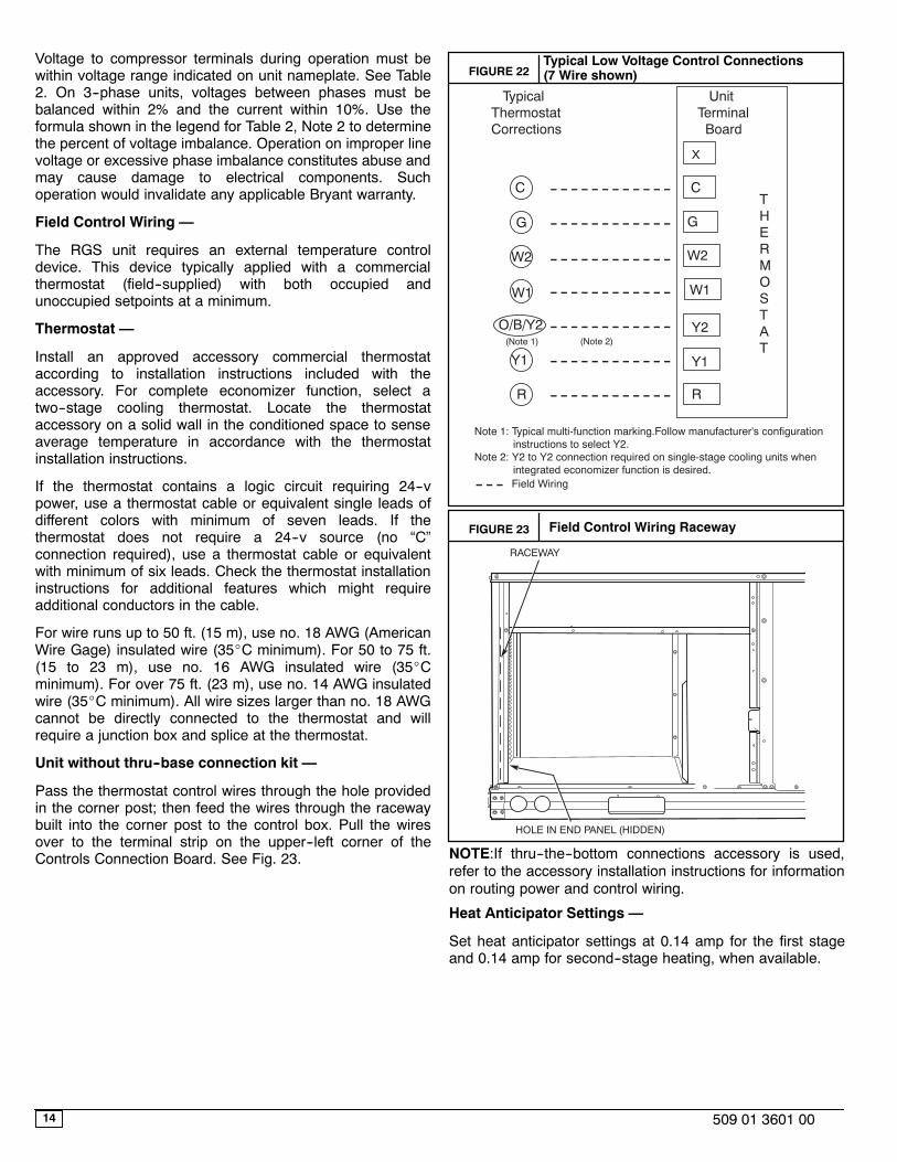
Pass the thermostat control wires through the hole providedin the corner post; then feed the wires through the racewaybuilt into the corner post to the control box. Pull the wiresover to the terminal strip on the upper--left corner of theControls Connection Board. See Fig. 23.
FIGURE 22Typical Low Voltage Control Connections(7 Wire shown)
X
C
G
W2
R
C
W2
G
W1
O/B/Y2 Y2
W1
R
Y1 Y1
TypicalThermostatCorrections
UnitTerminal Board
THERMOSTAT
(Note 1) (Note 2)
Note 1: Typical multi-function marking.Follow manufacturer's configuration instructions to select Y2.Note 2: Y2 to Y2 connection required on single-stage cooling units when integrated economizer function is desired.
Field Wiring
FIGURE 23 Field Control Wiring Raceway
RACEWAY
HOLE IN END PANEL (HIDDEN)
NOTE:If thru--the--bottom connections accessory is used,refer to the accessory installation instructions for informationon routing power and control wiring.
Heat Anticipator Settings —
Set heat anticipator settings at 0.14 amp for the first stageand 0.14 amp for second--stage heating, when available.
15509 01 3601 00
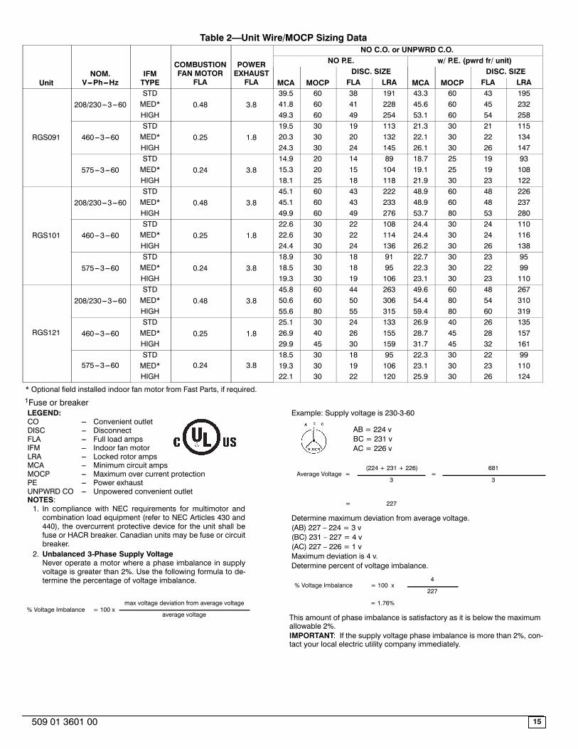
Table 2—Unit Wire/MOCP Sizing Data
UnitNOM.
V---Ph---HzIFMTYPE
COMBUSTIONFAN MOTOR
FLA
POWEREXHAUSTFLA
NO C.O. or UNPWRD C.O.NO P.E. w/ P.E. (pwrd fr/ unit)
MCA MOCPDISC. SIZE
MCA MOCPDISC. SIZE
FLA LRA FLA LRA
RGS091
208/230---3---60STD
0.48 3.839.5 60 38 191 43.3 60 43 195
MED* 41.8 60 41 228 45.6 60 45 232HIGH 49.3 60 49 254 53.1 60 54 258
460---3---60STD
0.25 1.819.5 30 19 113 21.3 30 21 115
MED* 20.3 30 20 132 22.1 30 22 134HIGH 24.3 30 24 145 26.1 30 26 147
575---3---60STD
0.24 3.814.9 20 14 89 18.7 25 19 93
MED* 15.3 20 15 104 19.1 25 19 108HIGH 18.1 25 18 118 21.9 30 23 122
RGS101
208/230---3---60STD
0.48 3.845.1 60 43 222 48.9 60 48 226
MED* 45.1 60 43 233 48.9 60 48 237HIGH 49.9 60 49 276 53.7 80 53 280
460---3---60STD
0.25 1.822.6 30 22 108 24.4 30 24 110
MED* 22.6 30 22 114 24.4 30 24 116HIGH 24.4 30 24 136 26.2 30 26 138
575---3---60STD
0.24 3.818.9 30 18 91 22.7 30 23 95
MED* 18.5 30 18 95 22.3 30 22 99HIGH 19.3 30 19 106 23.1 30 23 110
RGS121
208/230---3---60STD
0.48 3.845.8 60 44 263 49.6 60 48 267
MED* 50.6 60 50 306 54.4 80 54 310HIGH 55.6 80 55 315 59.4 80 60 319
460---3---60STD
0.25 1.825.1 30 24 133 26.9 40 26 135
MED* 26.9 40 26 155 28.7 45 28 157HIGH 29.9 45 30 159 31.7 45 32 161
575---3---60STD
0.24 3.818.5 30 18 95 22.3 30 22 99
MED* 19.3 30 19 106 23.1 30 23 110HIGH 22.1 30 22 120 25.9 30 26 124
* Optional field installed indoor fan motor from Fast Parts, if required.1Fuse or breakerLEGEND:CO --- Convenient outletDISC --- DisconnectFLA --- Full load ampsIFM --- Indoor fan motorLRA --- Locked rotor ampsMCA --- Minimum circuit ampsMOCP --- Maximum over current protectionPE --- Power exhaustUNPWRD CO --- Unpowered convenient outletNOTES:1. In compliance with NEC requirements for multimotor andcombination load equipment (refer to NEC Articles 430 and440), the overcurrent protective device for the unit shall befuse or HACR breaker. Canadian units may be fuse or circuitbreaker.
2. Unbalanced 3-Phase Supply VoltageNever operate a motor where a phase imbalance in supplyvoltage is greater than 2%. Use the following formula to de-termine the percentage of voltage imbalance.
% Voltage Imbalance = 100 xmax voltage deviation from average voltage
average voltage
Example: Supply voltage is 230-3-60
AB = 224 vBC = 231 vAC = 226 v
Average Voltage =(224 + 231 + 226)
=681
3 3
= 227
Determine maximum deviation from average voltage.(AB) 227 – 224 = 3 v(BC) 231 – 227 = 4 v(AC) 227 – 226 = 1 vMaximum deviation is 4 v.Determine percent of voltage imbalance.
% Voltage Imbalance = 100 x4
227
= 1.76%
This amount of phase imbalance is satisfactory as it is below the maximumallowable 2%.IMPORTANT: If the supply voltage phase imbalance is more than 2%, con-tact your local electric utility company immediately.

16 509 01 3601 00
FIGURE 24 Wiring for Optional Economizer
EconomizerBoard
Step 13 — Adjust Factory--Installed Options
Smoke Detector —
Smoke detector will be connected at the ControlsConnections Board, at terminals marked “Smoke Shutdown”.Remove jumper JMP 3 when ready to energize unit.
Economiser Occupancy Switch —
Refer to Fig. 24 for general EconoMi$er IV wiring. Externaloccupancy control is managed through a connection on theControls Connections Board.
If external occupancy control is desired, connect a time clockor remotely controlled switch (closed for Occupied, open forUnoccupied sequence) at terminals marked OCCUPANCY.Remove or cut jumper JMP 2 to complete the installation.
Step 14 — Install Accessories, As Required
Available accessories include:
Roof CurbThru--base connection kit (must be installed before unit isset on curb)
LP conversion kitManual outside air damperTwo--Position motorized outside air damperEconomizer (with control and integrated barometric relief)Winter start kitPower exhaustDifferential dry--bulb sensorOutdoor enthalpy sensorDifferential enthalpy sensorCO2 sensorLow ambient controlFlue gas discharge deflectorLouvered hail guardHood--type hail guardUV--C lamp kitPhase monitor control
Refer to separate installation instructions for information oninstalling these accessories.