Embed Size (px)
Citation preview
I N S T A L L A T I O N I N S T R U C T I O N S
Universal Interface Suspended CeilingProjector System
SYSAU
SYSAU Installation Instructions
2
DISCLAIMERMilestone AV Technologies and its affiliated corporations andsubsidiaries (collectively “Milestone”), intend to make thismanual accurate and complete. However, Milestone makes noclaim that the information contained herein covers all details,conditions or variations, nor does it provide for every possiblecontingency in connection with the installation or use of thisproduct. The information contained in this document is subjectto change without notice or obligation of any kind. Milestonemakes no representation of warranty, expressed or implied,regarding the information contained herein. Milestone assumesno responsibility for accuracy, completeness or sufficiency ofthe information contained in this document.
Chief® is a registered trademark of Milestone AV Technologies.All rights reserved.
DEFINITIONSMOUNTING SYSTEM: A MOUNTING SYSTEM is theprimary Chief product to which an accessory and/or componentis attached.
ACCESSORY: AN ACCESSORY is the secondary Chiefproduct which is attached to a primary Chief product, and mayhave a component attached or setting on it.
COMPONENT: A COMPONENT is an audiovisual itemdesigned to be attached or resting on an accessory or mountingsystem such as a video camera, CPU, screen, display,projector, etc.
WARNING: A WARNING alerts you to the possibility ofserious injury or death if you do not follow the instructions.
CAUTION: A CAUTION alerts you to the possibility ofdamage or destruction of equipment if you do not follow thecorresponding instructions.
IMPORTANT SAFETY INSTRUCTIONS
WARNING: Failure to read, thoroughly understand, andfollow all instructions can result in serious personal injury,damage to equipment, or voiding of factory warranty! It is theinstaller’s responsibility to make sure the mounting system isproperly assembled and installed using the instructionsprovided.
WARNING: Failure to provide adequate structural strengthfor this mounting system can result in serious personal injuryor damage to equipment! It is the installer’s responsibility tomake sure the structure to which this mounting system isattached can support five times the combined weight of allequipment. Reinforce the structure as required beforeinstalling the mounting system.
WARNING: Exceeding the weight capacity can result inserious personal injury or damage to equipment! It is theinstaller’s responsibility to make sure the combined weight ofall components attached to the SYSAU does not exceed 35 lbs(15.9 kg).
WARNING: Use this mounting system only for its intendeduse as described in these instructions. Do not useattachments not recommended by the manufacturer.
WARNING: Never operate this mounting system if it isdamaged. Return the mounting system to a service center forexamination and repair.
WARNING: Do not use this product outdoors.
IMPORTANT ! : The SYSAU has been designed to bemounted above or flush with a suspended ceiling secured by aWireVice system.
IMPORTANT ! : The SYSAU has been designed to support asingle electrical receptacle, a double electrical receptacle orboth.
NOTE: It is the installer’s responsibility to ensure that theenclosure is bonded to the ground in the switch box, inaccordance with the National Electric Code, ANSI/NFPA 70 or Canadian Electrical Code, CSA C22.1.
--SAVE THESE INSTRUCTIONS--
Installation Instructions SYSAU
3
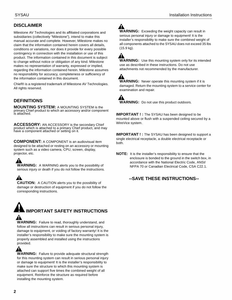
DIMENSIONS
155.46.12
184.27.25
116.84.60
66.52.62
50.31.98
POSITION FOR COLUMNSECURITY BOLT
MOVEABLE/REMOVABLEHOOKS
COLUMN LATCH
COLUMN CLAMP LEVER
58923.19 592
23.31633.624.94
47.71.88
21.5.85
1.03 ADJUSTMENT RANGE
REMOVABLE ELECTRICALINSTALL PLATE
SET SCREW LOCATIONS PROVIDEDTO SECURE PLATE TO CEILING GRID
234.29.22
COLUMN TRAVEL300.811.84
DIMENSIONS: [MILLIMETERS] INCHES
DIMENSIONS: [MILLIMETERS] INCHES
NOTE:THIS IS A 4 SHEET DRAWING1.SHEET 2 - CEILING PLATE2.SHEET 3 - PROJECTOR MOUNT AND COLUMN3.SHEET 4 - UNIVERSAL INTERFACE4.
503.319.82
MOUNT ANDCOLUMN ASSEMBLED
783.07
3.4186.6
8.6.34
36614.41
135.85.35
12.7.50
COLUMN ADJUSTMENTINCREMENT
415.216.35
28811.34
SYSAU Installation Instructions
4
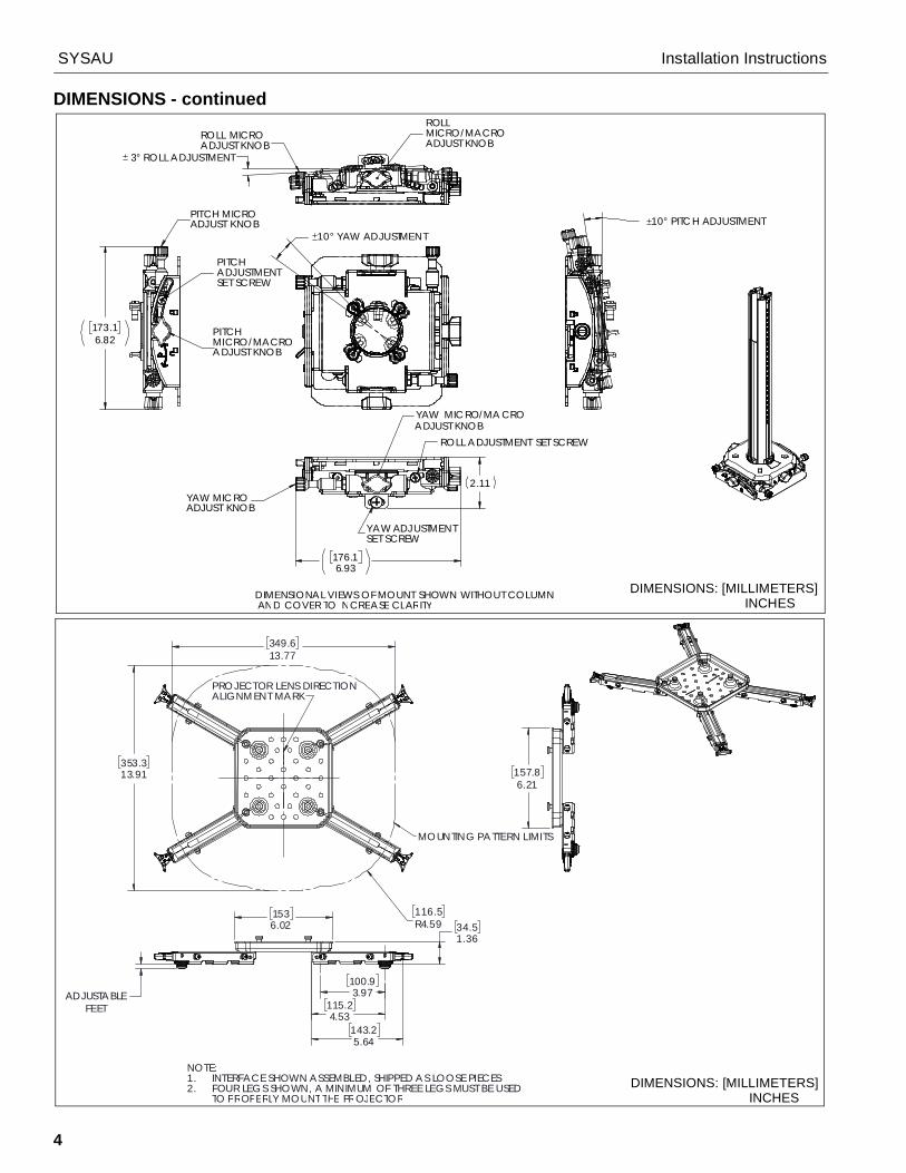
DIMENSIONS - continued
3° ROLL ADJUSTMENT
10° YAW ADJUSTMENT10° PITCH ADJUSTMENT
DIMENSIONAL VIEWS OF MOUNT SHOWN WITHOUT COLUMN AND COVER TO INCREASE CLARITY
YAW MICRO/MA CROADJUST KNOB
YAW MICROADJUST KNOB
ROLL ADJUSTMENT SET SCREW
YAW ADJUSTMENTSET SCREW
176.16.93
2.11
PITCH MICROADJUST KNOB
PITCHMICRO/MACROADJUST KNOB
PITCHADJUSTMENTSET SCREW
173.16.82
ROLLMICRO/MACROADJUST KNOB
ROLL MICROADJUST KNOB
DIMENSIONS: [MILLIMETERS] INCHES
349.613.77
116.5R4.59
353.313.91
MOUNTING PATTERN LIMITS
157.86.21
100.93.97
115.24.53
143.25.64
34.51.36
1536.02
ADJUSTABLEFEET
NOTE:INTERFACE SHOWN ASSEMBLED, SHIPPED AS LOOSE PIECES1.FOUR LEGS SHOWN, A MINIMUM OF THREE LEGS MUST BE USED2.TO PROPERLY MOUNT THE PROJECTOR
PROJECTOR LENS DIRECTIONALIGNMENT MARK
DIMENSIONS: [MILLIMETERS] INCHES

Installation Instructions SYSAU
5
LEGENDTighten Fastener
Apretar elemento de fijación
Befestigungsteil festziehen
Apertar fixador
Serrare il fissaggio
Bevestiging vastdraaien
Serrez les fixations
Loosen Fastener
Aflojar elemento de fijación
Befestigungsteil lösen
Desapertar fixador
Allentare il fissaggio
Bevestiging losdraaien
Desserrez les fixations
Phillips Screwdriver
Destornillador Phillips
Kreuzschlitzschraubendreher
Chave de fendas Phillips
Cacciavite a stella
Kruiskopschroevendraaier
Tournevis à pointe cruciforme
Open-Ended Wrench
Llave de boca
Gabelschlüssel
Chave de bocas
Chiave a punte aperte
Steeksleutel
Clé à fourche
By Hand
A mano
Von Hand
Com a mão
A mano
Met de hand
À la main
Hex-Head Wrench
Llave de cabeza hexagonal
Sechskantschlüssel
Chave de cabeça sextavada
Chiave esagonale
Zeskantsleutel
Clé à tête hexagonale
Pencil Mark
Marcar con lápiz
Stiftmarkierung
Marcar com lápis
Segno a matita
Potloodmerkteken
Marquage au crayon
Drill Hole
Perforar
Bohrloch
Fazer furo
Praticare un foro
Gat boren
Percez un trou
Adjust
Ajustar
Einstellen
Ajustar
Regolare
Afstellen
Ajuster
Remove
Quitar
Entfernen
Remover
Rimuovere
Verwijderen
Retirez
Optional
Opcional
Optional
Opcional
Opzionale
Optie
En option
Security Wrench
Llave de seguridad
Sicherheitsschlüssel
Chave de segurança
Chiave di sicurezza
Veiligheidssleutel
Clé de sécurité
SYSAU Installation Instructions
6
TOOLS REQUIRED FOR INSTALLATION
PARTS
#2 5/32"(security)[included]
(A) Hardware Bag 9900-002214 [Hardware bag markings match second letter of hardware]
AA (4)M2.5x10mm
AB (4) M3x10mm
AC (4) M4x10mm
AD (4) M5x14mm
AE (4) M6x14mm
AF (4) M4x25mm
AG (4) M6x25mm
AH (4) M5x25mm
AI (4) M3x25mm
AJ (4) M4
AK (4) .500x.257x.625"
AL1 (4) 10-24 x 3/8" AL2 (1)
5/32" (security)
AM (4) [Screw adapters]
AN (4) 1/4-20
(B) Hardware Bag 9900-002225 [Hardware bag markings match second letter of hardware]
BA (1) [Column trim ring]
BB (1) [Ceiling tile cutter] BC (4)
.262 x 1-5/16" BD (4)[Cable lock]
BE (4) 1/4" x 1-1/2"
BF (1) 1/4-20 x 5/8"
BG1 (1) 10-24 x 1/4" (security)
BG2 (1) 5/32" (security)
BH (8) 10-24 x 5/8"
BI (4) 1/16" x 25’ [Cable]
[Screw eye] [Wire anchor]
[Projectormount and column][Suspended ceiling plate assembly]
[Universal interface plate]
[Universal interface leg]
P (1)
R (1)
Q (4)
S (1)
(security)
Installation Instructions SYSAU
7
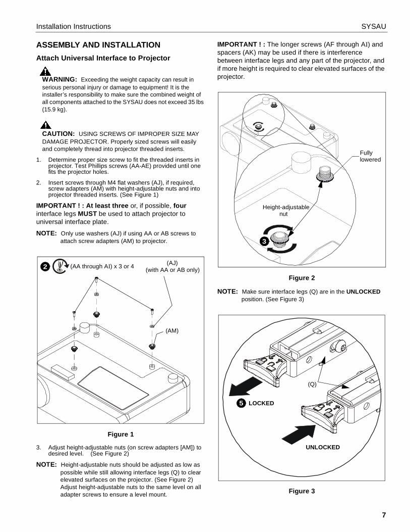
ASSEMBLY AND INSTALLATIONAttach Universal Interface to Projector
WARNING: Exceeding the weight capacity can result inserious personal injury or damage to equipment! It is theinstaller’s responsibility to make sure the combined weight ofall components attached to the SYSAU does not exceed 35 lbs(15.9 kg).
CAUTION: USING SCREWS OF IMPROPER SIZE MAYDAMAGE PROJECTOR. Properly sized screws will easilyand completely thread into projector threaded inserts.
1. Determine proper size screw to fit the threaded inserts inprojector. Test Phillips screws (AA-AE) provided until onefits the projector holes.
2. Insert screws through M4 flat washers (AJ), if required,screw adapters (AM) with height-adjustable nuts and intoprojector threaded inserts. (See Figure 1)
IMPORTANT ! : At least three or, if possible, fourinterface legs MUST be used to attach projector touniversal interface plate.
NOTE: Only use washers (AJ) if using AA or AB screws toattach screw adapters (AM) to projector.
Figure 1
3. Adjust height-adjustable nuts (on screw adapters [AM]) todesired level. (See Figure 2)
NOTE: Height-adjustable nuts should be adjusted as low aspossible while still allowing interface legs (Q) to clearelevated surfaces on the projector. (See Figure 2)Adjust height-adjustable nuts to the same level on alladapter screws to ensure a level mount.
IMPORTANT ! : The longer screws (AF through AI) andspacers (AK) may be used if there is interferencebetween interface legs and any part of the projector, andif more height is required to clear elevated surfaces of theprojector.
Figure 2
NOTE: Make sure interface legs (Q) are in the UNLOCKEDposition. (See Figure 3)
Figure 3
(AA through AI) x 3 or 4 (AJ)(with AA or AB only)2
(AM)
Fully
3
Height-adjustable nut
lowered
LOCKED
UNLOCKED
(Q)
5
SYSAU Installation Instructions
8
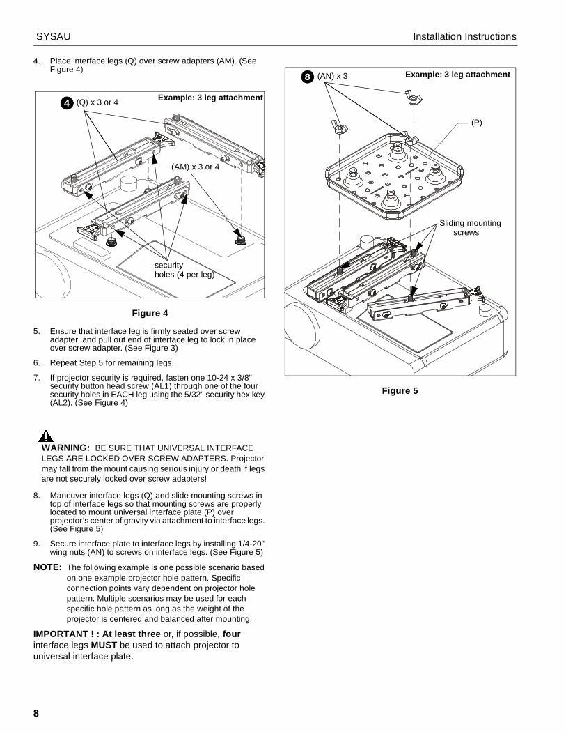
4. Place interface legs (Q) over screw adapters (AM). (SeeFigure 4)
Figure 4
5. Ensure that interface leg is firmly seated over screwadapter, and pull out end of interface leg to lock in placeover screw adapter. (See Figure 3)
6. Repeat Step 5 for remaining legs.
7. If projector security is required, fasten one 10-24 x 3/8"security button head screw (AL1) through one of the foursecurity holes in EACH leg using the 5/32" security hex key(AL2). (See Figure 4)
WARNING: BE SURE THAT UNIVERSAL INTERFACELEGS ARE LOCKED OVER SCREW ADAPTERS. Projectormay fall from the mount causing serious injury or death if legsare not securely locked over screw adapters!
8. Maneuver interface legs (Q) and slide mounting screws intop of interface legs so that mounting screws are properlylocated to mount universal interface plate (P) overprojector’s center of gravity via attachment to interface legs.(See Figure 5)
9. Secure interface plate to interface legs by installing 1/4-20"wing nuts (AN) to screws on interface legs. (See Figure 5)
NOTE: The following example is one possible scenario basedon one example projector hole pattern. Specificconnection points vary dependent on projector holepattern. Multiple scenarios may be used for eachspecific hole pattern as long as the weight of theprojector is centered and balanced after mounting.
IMPORTANT ! : At least three or, if possible, fourinterface legs MUST be used to attach projector touniversal interface plate.
Figure 5
(Q) x 3 or 44
(AM) x 3 or 4
Example: 3 leg attachment
securityholes (4 per leg)
Example: 3 leg attachment(AN) x 38
Sliding mounting screws
(P)

Installation Instructions SYSAU
9
INSTALLING THE SUSPENDED CEILING PLATENOTE: The SYSAU has been designed to be mounted above
or flush with a suspended ceiling secured by aWireVice system. The method used may bedetermined by the existing ceiling system.
1. Remove outlet plate from suspended ceiling plate assembly(R) if electrical outlet will be installed (See Figure 6), andinstall UL Listed Raco 256, 232 or equivalent UL Listedelectrical box (not included) to SYSAU outlet plate followinginstructions included with electrical box.
Figure 62. Determine exact location of column. Mark location on
lower (finished) side of ceiling tile. (See Figure 7)
• Flush with Suspended CeilingMark location on ceiling tile framework.
• Install on Top of Existing Ceiling Tile Mark location on lower (finished) side of ceiling tile.
Figure 7Be sure to consider the following items when determiningcolumn location:
• Dimensional offset of display/projector relative tocolumn (due to mount and/or interface).
• For Projectors: Any recommended dimensions ofprojector relative to target. (See installation instructionsincluded with the projector.)
3. Remove affected ceiling tile and any adjacent tiles requiredfor access.
4. Installing on Top of Existing Ceiling Tile only: Presscenter tip of ceiling tile cutter (BB) into finished side ofceiling tile at marked location. Cut extension column holethrough tile using back and forth motion.
5. Installing on Top of Existing Ceiling Tile only: Reinstallceiling tile with extension column hole. Ensure tile isoriented for proper location of hole.
6. Installing on Top of Existing Ceiling Tile only: Installsuspended ceiling plate assembly (R) on top of ceiling tileso that end brackets engage primary (1-1/2" (38mm) high)rails of ceiling framework. (See Figure 8)
Figure 8
7. Flush with Suspended Ceiling only: Install suspendedceiling plate assembly (R) on top of ceiling framework railsso that end brackets engage primary (1-1/2" (38mm) high)rails of ceiling framework. (See Figure 8)
8. Loosen two wing nuts at each end of ceiling plate assembly.(See Figure 9)
9. Raise or lower adjustable bracket, as necessary, at eachend of the ceiling plate assembly.
10. Tighten wing nuts on adjustable bracket at each end of theceiling plate assembly. (See Figure 9)
Figure 9
1
Electrical plate
2
6= 1.5" (38mm)
(R)
7
8
10
9
x 49
9
SYSAU Installation Instructions
10
11. Loosen three wing nuts in upper side of ceiling plateassembly (R) to adjust the lateral shift of the columnsupport. (See Figure 10)
12. Position column support (as required) to center supportover ceiling tile hole. (See Figure 10)
13. Tighten wing nuts to prevent further movement of columnsupport. (See Figure 10)
Figure 10
14. OPTIONAL -- Installing on Top of Existing Ceiling Tileonly: Mark location of electrical cutout on ceiling tile withpencil.
15. Examine ceiling structure (concrete or wood) above ceilingplate assembly (R) to identify four support cable anchorlocations. Each location should be approximately 15°outboard of support holes in ceiling plate assembly (R).(See Figure 11)
16. Mark locations with pencil.
Figure 11
17. Remove ceiling plate assembly (R) and ceiling tile.
OPTIONAL: Cut electrical box opening in ceiling tile at markedlocation.
Installing Support Cable
WARNING: Failure to provide adequate structural strengthfor this component can result in serious personal injury ordamage to equipment! It is the installer’s responsibility tomake sure the structure to which this component is attachedcan support five times the combined weight of all equipment.Reinforce the structure as required before installing thecomponent.
Solid Concrete Ceiling Structure
WARNING: Anchors must be installed into structurallysound solid concrete with a minimum thickness of 4"(101.6mm) or greater. Installation into hollow concrete block,mortar, or concrete that exhibits cracking, spalling, or otherdefects may result in failure of anchor and serious personalinjury or damage to equipment!
1. Drill 1/4" diameter x 1-1/2" deep hole at each marked cableanchor support location (See Figure 12). Ensure hole is atleast 2-1/2" from nearest concrete edge. Remove debrisfrom hole.
Figure 12
2. Tap anchor (BE) into each hole until the anchor head isseated in the hole. (See Figure 12)
WARNING: Failure to properly set anchor may result infailure of anchor and serious personal injury or damage toequipment!
3. Using claw portion of hammer, set each anchor (BE) bypulling it out of hole approximately 1/4" (6.4mm). (SeeFigure 12)
4. Insert portion of manufactured loop on cable (BI) throughhole in anchor (BE). Insert end of cable (BI) through loop.Repeat for 3 remaining support locations. (See Figure 12)
12
11
13x 3
16
15°
15°
x 4
(R)
x 4
x 4
1
2
3
4
1/4"
(BI)(BE)
Installation Instructions SYSAU
11
Wood Ceiling Structure
WARNING: Anchors must be installed into wood thatmeasures at least 3-1/2" x 1-1/2" (88.9mm x 38.1mm), andthe anchor must install in the center of the narrower (1-1/2"[38.1mm]) face.
1. Drill 5/32" diameter x 2" deep hole at each marked cableanchor support location (See Figure 13). Remove debrisfrom hole.
Figure 13
2. Fully thread eye lag (BC) into each hole (See Figure 13).
3. Route end of cable (BI) through eye lag (BC) and thenthrough cable loop (See Figure 13). Repeat for 3 remainingsupport locations.
Completing Ceiling Plate Assembly Installation1. Installing on Top of Existing Ceiling Tile only: Reinstall
ceiling tile with extension column hole. Ensure tile isoriented for proper location of hole.
2. Installing on Top of Existing Ceiling Tile only: Reinstallceiling plate assembly (R) on top of ceiling tile so thatextension column support is centered over hole in tile.
3. Position ceiling plate assembly (R) with four screws (BH) asrequired:
• For 625mm (24-5/8 in.) Framework: Install screwsthrough end bracket inside holes. (See Figure 14)
• For 610mm (24 in.) Framework: Install screwsthrough end bracket inside holes. (See Figure 14)
• For 600mm (23-5/8 in.) Framework: Install screwsthrough end bracket outside holes. (See Figure 15)
OPTIONAL: An additional four screws (BH) may be used (ifdesired) to further secure the ceiling plate assembly in place andprevent any movement. (See Figure 14) and (See Figure 15)
Figure 14
Figure 15
1
5/32"2 3(BC) (BI)
3 (BH) x 4
625mm (24-5/8 in.)610mm (24 in.)
(R)
OPTIONALadditionalfasteners (BH)
OPTIONALadditionalfasteners (BH)
3
600mm (23-5/8 in.)
(BH) x 4
R
OPTIONALadditionalfasteners (BH)
OPTIONALadditionalfasteners (BH)
SYSAU Installation Instructions
12
CAUTION: Failure to properly tension cables (BI) mayresult in damage to ceiling tile framework!
4. Thread each cable (BI) completely through cable lock (BD),corresponding hole in corner of ceiling plate assembly (R),and completely through opposite side of cable lock (BD).(See Figure 16)
5. Adjust cable tension until ceiling plate assembly (R) issupported entirely and evenly by all four support cables, butnot so tight as to distort ceiling tile framework.
NOTE: Cable lock (BD) will allow cable to enter from only onedirection per side, indicated by arrows on lock. Depressspring loaded pins on cable lock (BD) to release cabletension.
Figure 16
Installing Projector Mount and Column
WARNING: Exceeding the weight capacity can result inserious personal injury or damage to equipment! It is theinstaller’s responsibility to make sure the combined weight ofall components attached to the SYSAU up to (and including)the display/projector, does not exceed 35 lbs (15.9 kg).
NOTE: The column may be shortened if there are spacelimitations above the ceiling plate.
1. OPTIONAL: Use a band saw or similar sawing device toremove the desired length of column.
IMPORTANT ! : At least one full hole (on side of column)must be visible above the upper clamping system. (SeeFigure 18)NOTE: Be sure to line up the projector mount so that it faces
the screen. The projector mount lock will appear on theleft side of the assembly. (See Figure 17)
2. Install projector mount and column (S) from underneath andup through suspended ceiling plate assembly (R). (SeeFigure 17)
3. Move projector mount and column upward to desiredposition. The mount and column will lock into place as soonthe column’s upward motion is stopped.
4. If necessary, pull up on the release ring found on thesuspended ceiling plate assembly (R) in order to move thecolumn downward. (See Figure 18)
Figure 175. Push lock lever up to stabilize motion of the projector
mount. (See Figure 18)
Figure 186. Install one 1/4-20 x 5/8" button head screw (BF) into
extension column in first opening above column collar,tightening firmly against column. (See Figure 18)
7. Install one 10-24 x 1/4" security button head screw (BG1)into column mechanism on suspended ceiling plateassembly to prevent movement of the release ring andfurther movement of the column. (See Figure 18)
4 (BI, BD) x 4
(BI)
(BD)
(R)
spring-loaded pin
Projectormount lock
2
SCREEN
(S)
(R)
SIDE VIEW
(BG1)7
4
5
SCREEN
Release ringLocklever
Upperclamping
6 (BF)
Location forsecurity screw(BG1)
system
Installation Instructions SYSAU
13
8. Flush with Suspended Ceiling only: Re-install ceiling tileto fit along side(s) of SYSAU. (See Figure 19)
Figure 19
9. OPTIONAL: Install column trim ring (BA) on extensioncolumn below or flush with ceiling tile. (See Figure 20)
Figure 20
Installing Projector
WARNING: IMPROPER INSTALLATION CAN LEAD TOPROJECTOR FALLING RESULTING IN SERIOUSPERSONAL INJURY OR DAMAGE TO EQUIPMENT. Makecertain mounting slots in projector mount base slide underthumb screws and that screws are seated in the back of slots.
1. Orient projector with interface bracket so that the projectormount lock appears on the left side of the assembly (whenviewed from screen). (See Figure 21)
2. Lift projector so that thumb nuts on attached interfacebracket are aligned with mounting slots in projector mountbase.
3. Slide projector with interface bracket into mounting slots inmount base until thumb nuts are seated in the narrowportion of mounting slots against the opposite side ofmounting slots. (See Figure 21)
Figure 21
4. Move locking lever to "Locked" position. (See Figure 22)
5. Insert key into lock and turn to secure projector to projectormount.
Figure 22
8
(BA)9
SCREEN
Example: 3 leg attachment
Mountingslot
Thumb nut
Thumb nuts
2
3
SCREEN
4
5
LOCKposition
UNLOCKposition
Lock
Locking lever
SYSAU Installation Instructions
14
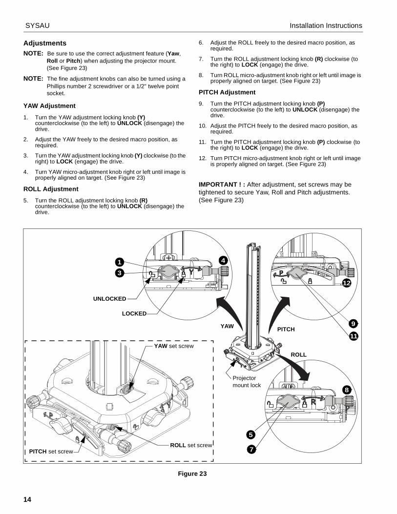
AdjustmentsNOTE: Be sure to use the correct adjustment feature (Yaw,
Roll or Pitch) when adjusting the projector mount.(See Figure 23)
NOTE: The fine adjustment knobs can also be turned using aPhillips number 2 screwdriver or a 1/2" twelve pointsocket.
YAW Adjustment
1. Turn the YAW adjustment locking knob (Y)counterclockwise (to the left) to UNLOCK (disengage) thedrive.
2. Adjust the YAW freely to the desired macro position, asrequired.
3. Turn the YAW adjustment locking knob (Y) clockwise (to theright) to LOCK (engage) the drive.
4. Turn YAW micro-adjustment knob right or left until image isproperly aligned on target. (See Figure 23)
ROLL Adjustment
5. Turn the ROLL adjustment locking knob (R)counterclockwise (to the left) to UNLOCK (disengage) thedrive.
6. Adjust the ROLL freely to the desired macro position, asrequired.
7. Turn the ROLL adjustment locking knob (R) clockwise (tothe right) to LOCK (engage) the drive.
8. Turn ROLL micro-adjustment knob right or left until image isproperly aligned on target. (See Figure 23)
PITCH Adjustment
9. Turn the PITCH adjustment locking knob (P)counterclockwise (to the left) to UNLOCK (disengage) thedrive.
10. Adjust the PITCH freely to the desired macro position, asrequired.
11. Turn the PITCH adjustment locking knob (P) clockwise (tothe right) to LOCK (engage) the drive.
12. Turn PITCH micro-adjustment knob right or left until imageis properly aligned on target. (See Figure 23)
IMPORTANT ! : After adjustment, set screws may betightened to secure Yaw, Roll and Pitch adjustments.(See Figure 23)
Figure 23
8
7
5
3
41
YAW
ROLL
PITCH11
12
9
Projectormount lock
UNLOCKED
LOCKED
PITCH set screw
YAW set screw
ROLL set screw
Installation Instructions SYSAU
15
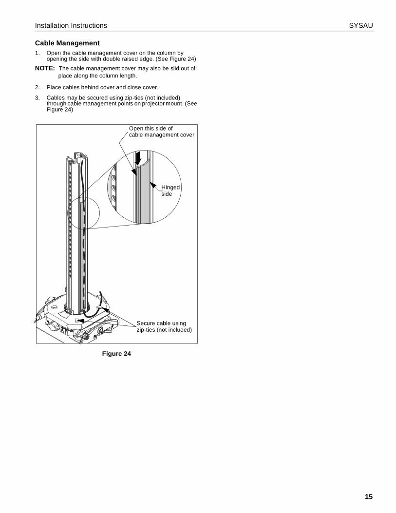
Cable Management1. Open the cable management cover on the column by
opening the side with double raised edge. (See Figure 24)NOTE: The cable management cover may also be slid out of
place along the column length.
2. Place cables behind cover and close cover.
3. Cables may be secured using zip-ties (not included)through cable management points on projector mount. (SeeFigure 24)
Figure 24
Open this side ofcable management cover
Hingedside
Secure cable usingzip-ties (not included)

SYSAU Installation Instructions
USA/International A 6436 City West Parkway, Eden Prairie, MN 55344P 800.582.6480 / 952.225.6000F 877.894.6918 / 952.894.6918
Europe A Franklinstraat 14, 6003 DK Weert, NetherlandsP +31 (0) 495 580 852F +31 (0) 495 580 845
Asia Pacific A Office No. 918 on 9/F, Shatin Galleria18-24 Shan Mei StreetFotan, Shatin, Hong Kong
P 852 2145 4099F 852 2145 4477
Chief, a products division ofMilestone AV Technologies
8800-002985 Rev002017 Milestone AV Technologies
www.milestone.com09/17