Embed Size (px)
Citation preview

®
to the Expertg
Installation Instructions
IMPORTANT: This installation instruction contains basic unit
installation information including installation of field control
devices. For information on unit start-up, service, and operation,
refer to the unit Controls, Start-Up, Operation, Service, and
Troubleshooting Instructions also enclosed in the unit literature
packet.
TABLE OF CONTENTS
PAGE
SAFETY CONSIDERATIONS ......................... 1
INSTALLATION .................................... 2
Step 1 - Provide Unit Support ......................... 2
Step 2 - Remove Shipping Rails ....................... 2
Step 3 - Rig and Place Unit ........................... 2
Step 4 - Field Fabricate Ductwork ...................... 9
Step 5 - Make Unit Duct Connections ................... 9
Step 6 - Install Flue Hood and Inlet Hood ............... 10
Step 7 - Trap Condensate Drain ...................... 10
Step 8 - Install Gas Piping ........................... 11
Step 9 - Orifice Change ............................. 11
Step 10 - Make Electrical Connections ................. 12
Step 11 - Install Outdoor-Air Hood ................... 18
Step 12 - Position Optional Power Exhaust orBarometric Relief Damper Hood .............. 19
Step 13 - Non-Fused Disconnect ..................... 19
Step 14 - Install All Accessories ...................... 19
Step 15 - Configure Controls ........................ 19
SAFETY CONSIDERATIONS
Installation and servicing of air-conditioning equipment can be
hazardous due to system pressure and electrical components. Only
trained and qualified service personnel should install, repair, or
service air-conditioning equipment.
Untrained personnel can perform the basic maintenance functions
of replacing filters. All other operations should be performed by
trained service personnel. When working on air-conditioning
equipment, observe precautions in the literature, tags and labels
attached to the unit, and other safety precautions that may apply.
Follow all safety codes. Wear safety glasses and work gloves. Use
quenching cloth for unbrazing operations. Have fire extinguishers
available for all brazing operations.
Recognize safety information. This is the safety-alert symbol /_.
When you see this symbol on the furnace and in instructions or
manuals, be alert to the potential for personal iniury.
Understand the signal words DANGER, WARNING, and
CAUTION. These words are used with the safety-alert symbol.DANGER identifies the most serious hazards which will result in
severe personal iniury or death. WARNING signifies a hazard
which could result in personal iniury or death. CAUTION is used
to identify unsafe practices which may result in minor personal
iniury or product and property damage. NOTE is used to highlight
suggestions which will result in enhanced installation, reliability, or
operation.
ELECTRICALSHOCK HAZARD
Failure to follow this warning could result in personal
iniury or death.
Before installing or servicing system, always turn off main
power to system. There may be more than one disconnectswitch.
UNIT OPERATION AND SAFETY HAZARD
Failure to follow this caution may result in personal iniuryor equipment damage,
Puron ® (R-410A) refrigerant systems operate at higherpressures than standard R-22 systems, Do not use R-22service equipment or components on Puron refrigerantequipment,
H
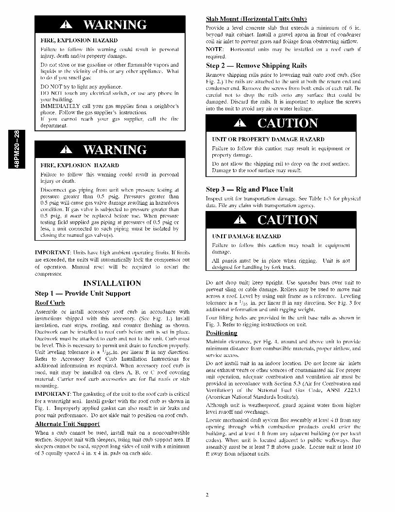
FIRE, EXPLOSION HAZARD
Failure to follow this warning could result in personal
injury, death and/or property damage.
Do not store or use gasoline or other flammable vapors and
liquids in the vicinity of this or any other appliance. What
to do if you smell gas:
DO NOT try to light any appliance.
DO NOT touch any electrical switch, or use any phone inyour building.
IMMEDIATELY call your gas supplier from a neighbor'sphone. Follow the gas supplier's instructions.
If you cannot reach your gas supplier, call the fire
department.
FIRE, EXPLOSION HAZARD
Failure to follow this warning could result in personal
injury or death.
Disconnect gas piping from unit when pressure testing at
pressure greater than 0.5 psig. Pressures greater than
0.5 psig will cause gas valve damage resulting in hazardous
condition. If gas valve is subjected to pressure greater than
0.5 psig, it must be replaced before use. When pressure
testing field-supplied gas piping at pressures of 0.5 psig or
less, a unit connected to such piping must be isolated by
closing the manual gas valve(s).
IMPORTANT: []nits have high ambient operating limits. If limits
are exceeded, the units will automatically lock the compressor out
of operation. Manual reset will be required to restart the
compressor.
INSTALLATION
Step 1 -- Provide Unit SupportRoof Curb
Assemble or install accessory roof curb in accordance with
instructions shipped with this accessory. (See Fig. 1.) Install
insulation, cant strips, roofing, and counter flashing as shown.
Ductwork can be installed to roof curb before unit is set in place.Ductwork must be attached to curb and not to the unit. Curb must
be level. This is necessary to permit unit drain to function properly.
Unit leveling tolerance is - 1/16_in. per linear ft in any direction.
Refer to Accessory Roof Curb Installation Instructions for
additional information as required. When accessory roof curb is
used, unit may be installed on class A, B, or C roof coveringmaterial. Carrier roof curb accessories are for flat roofs or slab
mounting.
IMPORTANT: The gasketing of the unit to the roof curb is critical
for a watertight seal. Install gasket with the roof curb as shown in
Fig. 1. Improperly applied gasket can also result in air leaks and
poor unit performance. Do not slide unit to position on roof curb.
Alternate Unit SupportWhen a curb cannot be used, install unit on a noncombustible
surface. Support unit with sleepers, using unit curb support area. If
sleepers cannot be used, support long sides of unit with a minimum
of 3 equally spaced 4-in. x 4-in. pads on each side.
Slab Mount (Horizontal Units Only)Provide a level concrete slab that extends a minimum of 6 in.
beyond unit cabinet. Install a gravel apron in front of condenser
coil air inlet to prevent grass and foliage from obstructing airflow.
NOTE: Horizontal units may be installed on a roof curb if
required.
Step 2 -- Remove Shipping Rails
Remove shipping rails prior to lowering unit onto roof curb. (See
Fig. 2.) The rails are attached to the unit at both the return end andcondenser end. Remove the screws from both ends of each rail. Be
careful not to drop the rails onto any surface that could be
damaged. Discard the rails. It is important to replace the screws
into the unit to avoid any air or water leakage.
[]NIT OR PROPERTY DAMAGE HAZARD
Failure to follow this caution may result in equipment orproperty damage.
Do not allow the shipping rail to drop on the roof surface,Damage to the roof surface may result,
Step 3 -- Rig and Place Unit
Inspect unit for transportation damage. See Table 1-3 for physical
data. File any claim with transportation agency.
[]NIT DAMAGE HAZARD
Failure to follow this caution may result in equipmentdamage,
All panels must be in place when rigging. []nit is notdesigned for handling by fork truck.
Do not drop unit; keep upright. Use spreader bars over unit to
prevent sling or cable damage. Rollers may be used to move unit
across a roof. Level by using unit frame as a reference. Leveling
tolerance is - 1/16-in. per linear ft in any direction. See Fig. 3 for
additional information and unit rigging weight.
Four lifting holes are provided in the unit base rails as shown in
Fig. 3. Refer to rigging instructions on unit.
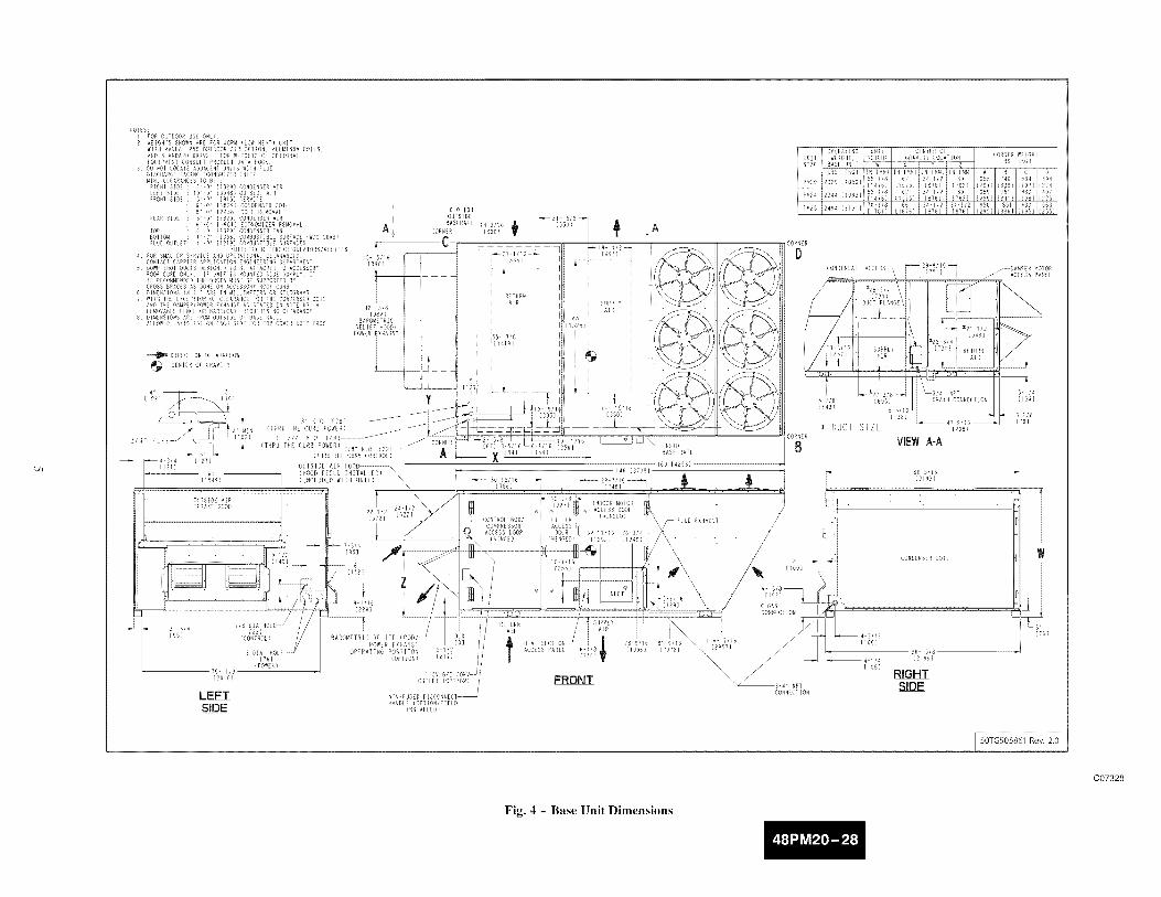
Positioninu
Maintain clearance, per Fig. 4, around and above unit to provide
minimum distance from combustible materials, proper airflow, andservice access.
Do not install unit in an indoor location. Do not locate air inlets
near exhaust vents or other sources of contaminated air. For proper
unit operation, adequate combustion and ventilation air must be
provided in accordance with Section 5.3 (Air for Combustion and
Ventilation) of the National Fuel Gas Code, ANSI Z223.1
(American National Standards Institute).
Although unit is weatherproof, guard against water from higher
level runoff and overhangs.
Locate mechanical draft system flue assembly at least 4 ft from any
opening through which combustion products could enter the
building, and at least 4 ft from any adjacent building (or per local
codes). When unit is located adjacent to public walkways, flue
assembly must be at least 7 ft above grade. Locate unit at least 10
ft away from adjacent units.

BACK
B' 3 i/8"{1604}
REF BOTHOPENINGS
iiiiiiiiiiiiiii
ii
1249) 1148)
O'3(78)
1221
SUPPLYOPENING
CURB
no (R)
9' 6 7/16"i290B}
NOTES:
i ROOECURB ACCESSORY IS SHIPPED DISASSEMBLED
B DIMENSIONS IN () ARE IN MILLIMETERS
3 EZZ_DIRECTION OF AIRFLOW
4 ROOF CURB: i6 GA (VA03 56) STEEL
B TO PREVENT THE HAZARD OF STAGNANT WATER BUILD UP iN THE UNI
PO NO EXCEED CURB LEVELING TOLERANCES
6 CLEARANCE BETWEEN UNET BASE RAIL AND CURB FLANGE IS i/4 IN (6 MM)
FRONI
ON EACH SIDE
_ O' 111
(25)
A
J
ATTACH DUCT TO ROOFCURB
i_UTLINE OF BOTTOM
'"i: O_ UNIT
PLAH IEW on ROOF CURB
/_ABKET REF
0"-1 3/41'_(44}
RE
WITH 1 INCH FIBERGLASSINSULATION
(76)
SECTION C-C
ASE AILO UN '<6}
MAX CURS LEVELING TOLERANCES:
ROOFCURB A
= BEG
CRRFCBRBOBBCOOCRRFCBRBOBNCO0
BACK
ASKET_(SUPPLIEB WITH
X CURB_ RETURNJ _-a ENBI
\N
/I
\,
J
_1" 9 l/1B II(B351
RETURNAIR
VIEW"A-A"
/
Fig. 1 - Roof Curb Details
C07327

SHIPPING RAILS
Fig. 2 - Shipping Rail Removal
C06273
CAUTION: NOTICE TO RIGGERS:ALL PANELS MUST BE IN PLACE WHEN RIGGING.
NOTICETO RIGGERS: Rig by inserting hooks into unit base rails as shown. Maintain a distanceof 120 inches (3048 MM) from top of unit to eyehook. Leave coil cover attached to unit whilerigging to protect coil of unit from damage.
MAXUNIT SIZE WEIGHT
(LBS}_
PG20 3825
PG24 4075
PG28 4300
PM20 3338
PM24 3371
P_28 3633
- DOES NOT INCLUDE
NOTE:Add 1501b(68kg)
CENTER OF GRAVITY (IN) /'ix Y Z
73.0 36.0 30.5
77.5 36.7 31.0
70.9 35.1 34.3
62.0 34.5 30.0 /'_
_o°_,_,o_o //\ ,_oOiO;.,
for domestic crating.
Fig. 3 - Rigging Details
NOTE:SEE LABELFOR UNITLOCATIONON ROOFCURB
50TG503592 4.0
C07241
'.Ji
NOTES:i NOR OU/DOORUSE ONLY2 WEiGHFSSHOWNARE FOR48PM (LOW HEAT) UNIT
WITH MANUAL25% OUTDOORAiR OPTION, ALUMINU_ COilS,AND STANDARDDR_VE FORWEiGhTS OE OPTIONALEOU/PMENTCONSULTRROBDC1DANA800N
3 DO _0/ LOCATEAUJACENPUNITS WI_N FLUEDISCHARGEFAN)NGECONOMIZERINLET¸MIN CLEARANCESTO BERIGHT SIDE : 6 ¸ 0" _/8291 CONDENSERAiRLiPP SIDE lO0 ' _3048_ OUPSiUEAIRFRONTSIDE : 3' 0'¸ [NI5] SERVICE
• 6 ¸ N¸' [1829] CONDENSERCOIL8' O_' [N4BN] COIL REMOVAL
REAR SIDE : 6 ¸ 0" _1829] CONDENSERAiR• 6 ¸ 6 =' [1981] ECONOMIZERREMOVAL
TOP 6O _18R9] CONDENSERFANBOrTO_ : / ¸ N" [S56] CO_BUSTINLESUHFACE{W/O CUNB)FLUE OUTLET: 4 ¸ 0" _IRI9] COMBUSTIBLESURFACES
/UTILITY MEPERS/NEUULATORS/RELiEFS4 NORSMALLERSERVICEANDOPERATIONALCLEARANCES,
CONTACTCARRIERAPPL)CATIO_ E_GINEER)NGBE_ART_EN/S DOWNSN07 DUCTSDESIGNEDTO BE ATTACKEDTO ACCESSORY
_OOr CURDONLY¸ IF UNIT IN MOUNTEDSIDE S_PPLY IT[S RECOMMENDED7HE DUCTSMDSPBE SUPPORTEDR¥CROSSBRACESAS BONEON ACCESSORYNOONCURB
6 01MENS_ONS_N _ ] ARE IN MILL!mETERSOR 4!LOURAMS7 WITN TNE E×CEPTIO_ OF CLEARANCEFOR_HE CONDENSERCOIL
ANDTHE DAMPER/POWEREXHAUSTAS STATEDiN NOTE_3, AREMOVABLEPENCEOR BARRICADEREOU)RESNOCLEANANCE
8 DIMENSIONSANE FROMOUTSIDEOF BASERAILALLOWO S/iN _N_ ON EAC_ S)BE NOR70P COVENDRIP EDGE
_D_RECPION OE AIRFLOW
CENIER OF GRAVI1Y
r
I
A÷
[3No]
42 _ 5/8[IO82]
4 I1 3 'l
LION] {76)
3 '_ HO {76] _41MiN (THRU THE CURB POWER)
3/4" P / {THRU THE CURB POWER) 7/8' NO5_,
F
i,{786]
17718
÷eiL [327]i
CONTROL BOX/ FILTERCOMPRESSOR ACCESSACCESSDOOR BOOR
<)NGEB) (iliNGED)iN 1/16
" / oio _
q
I
_A
OPERATIRO UNIT CENTEROFi UNIIi WEOH1, HEIGHT GRAV]TY LOCATION
SIZE i BASE UNIP 7 W]N [_M]iiN [M_]iIN I_M]
_£ [58:]78[ 6N iS4 1/2 i 30i PM2o i2329 [/_6] i [14761 i [S575] _ [876] i i762]
[14761 115)5] , i762!
[17811 {1676]i [876} i _816/
CORNER WEiG_I
LNS {KG}
655 746 434 494{297} {358} {197} {284]659 751 43N _97
i29_} i341} ii98] [225]65O 851 43O 563
[295} _386] [i95] [255]
CONDENSATE ACCESS_ _29 9/16 _''_k {751] DAMPER _010R
_-'ACOESS PANEL
÷ DUCT SIZE [_2os
B VIEW AIA
+.,............71
J
! 7/8 BIA HOLE
[95] (CONTROL)
B DIA NOLE[76]
(POWER)79 lib[NOLO]
LEFTSIDE
BAROMETRIC RELIEFPOWEREXRAUSi
OPERAliNG POSIIION 8 llN(OPTION) [217]
IlSV UP] /OUTLET (OPTION) '
/NON-FUSEBDISCONNECI_NA_BLE (OPTION/FIELD
]RSTALLEB)
%"©G •
REIURN SUPRIYAR A[R
tHE ....... _ ............ /_x_....ACCESSPANE 6 I/8 {199N] {NOTR] 2957]
{SN
FRONT _S/_ I ,_T
CONNEClION
8[_195?
RIGHTSIDE
LS,,[761
I 50TG505861 Rev. 2.0
C07328
Fig. 4 - Base Unit Dimensions
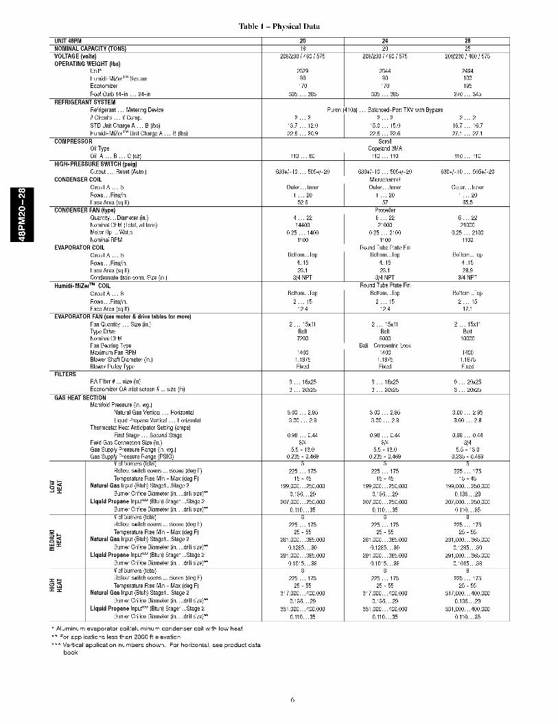
Table I - Physical Data
20 24 2818 20 25
208/230/ 460 / 575 208/230/ 460 / 575 208/230/ 460 / 575
2329 2344 249480 80 100
170 170 195
305 ... 385 305 ... 385 270 ... 345
Puron(410a) ... Balanced-PortTXV with Bypass2...2 2...2 2...2
13.7 ... 12.0 15.0 ... 15.0 16.7 ... 16.7
22.6 ... 20.9 22.6 ... 22.6 27.1 ... 27.1Scroll
Copeland3MA110 ... 60 110 ... 110 110 ... 110
630+/-10 ... 505+/-20 630+/-10 ... 505+/-20 630+/-10 ... 505+/-20Microchannel
Outer... Inner Outer... Inner Outer... Inner1 ... 20 1 ... 20 1 ... 20
52.6 57 65.5
Propeller4 ... 22 6 ... 22 6 ... 2214400 21000 21000
0.25 ... 1400 0.25 ... 2100 0.25 ... 21001100 1100 1100
RoundTube Plate Fin
Bottom...Top Bottom...Top Bottom...Top4..15 4..15 4..15
23.1 23.1 28.93/4 NPT 3/4 NPT 3/4NPT
RoundTube Plate Fin
Bottom...Top Bottom...Top Bottom...Top2 ... 15 2 ... 15 2 ... 15
12.4 12.4 17.1
UNIT48PM
NOMINALCAPACITY (TONS)
VOLTAGE (volts)OPERATINGWEIGHT (Ibs)
Unit*
Humidi-MiZerTM SystemEconomizer
RoofCurb N-in ... 24-in
REFRIGERANTSYSTEM
Refrigerant... MeteringDevice
#Circuits ... #Comp.STD Unit ChargeA ... B (Ibs)
Humidi-MiZerTM Unit ChargeA ... B (Ibs)COMPRESSOR
OilType
Oil A ... B ... C(oz)HIGH-PRESSURESWITCH(psig)
Cutout ... Reset (Auto.)CONDENSERCOIL
CircuitA ... B
Rows... Fins/in.FaceArea (sqft)
CONDENSERFAN (type)Quantity... Diameter(in.)NominalCFM (Total,all fans)MotorHp ... WattsNominalRPM
EVAPORATORCOILCircuitA ... B
Rows... Fins/in.
FaceArea (sqft)Condensatedrainconn. Size (in.)
Humidi-MiZerTM COIL
CircuitA ... B
Rows... Fins/in.
FaceArea (sqft)EVAPORATORFAN (see motor &drive tablesfor more)
FanQuantity ... Size (in.)Type DriveNominalCFM
FanBearingTypeMaximumFan RPM
BlowerShaft Diameter(in.)BlowerPulleyType
2 ... 15xllBelt
7200
RAFilter # ... size (in)
EconomizerCA inlet screen # ... size (in)GAS HEATSECTION
ManifoldPressure(in. wg.)NaturalGas Vertical ... Horizontal
UquidPropaneVertical ... HorizontalThermostat HeatAnticipatorSetting(amps)
First Stage ... SecondStageField Gas ConnectionSize (in.)Gas SupplyPressure Range(in.wg.)Gas SupplyPressure Range(PSIG)
#of burners(total)Rolloutswitchopens ... closes (deg F)TemperatureRise Min - Max(deg F)
Natural Gas Input(Btuh)Stage1...Stage 2J_= BurnerOrifice Diameter(in....drill size)**
Liquid Propane Input*** (Btuh)Stage1...Stage 2
BurnerOrifice Diameter(in....drill size)**
#of burners(total)Rolloutswitchopens ... closes (deg F)
_,-,_ TemperatureRise Min - Max(deg F)5_m_ NaturalGas Input(Btuh)Stage1...Stage 2.u = BurnerOrifice Diameter(in....drill size)**
Liquid Propane Input*** (Btuh)Stage1...Stage 2BurnerOrifice Diameter(in....drill size)**
#of burners(total)
z: _ Rolloutswitchopens ... closes (deg F)
'_Z"_ TemperatureRise Min - Max(deg F)Natural Gas Input(Btuh)Stage1...Stage 2
BurnerOrifice Diameter(in....drill size)**Liquid Propane Input*** (Btuh)Stage1...Stage 2
BurnerOrifice Diameter(in....drill size)**
Aluminum evaporator coil/aluminum condenser coil with low heat
** For applications less than 2000 ft elevation*** Vertical application numbers shown. For horizontal, see product data
book
1400
1.1875
Fixed
2 ... 15xllBelt
8000Ball - ConcentricLock
14001.1875Fixed
2 ... 15xllBelt
10000
1400
1.1875
Fixed
FILTERS
9 ... 16x25 9 ... 16x25 9 ... 20x25
3 ... 20x25 3 ... 20x25 3 ... 20x25
0.98 ... 0.443/4
5.5 - 13.00.235 - 0.469
5225 ... 175
15 - 45
199,000... 250,0000.136...29
207,000...250,0000.110...35
8
225 ... 17525 - 55
281,000...365,0000.1285... 30
291,000...365,0000.1015...38
8225 ... 175
25 - 55
317,000... 400,0000.136...29
331,000...400,0000.110...35
0.98 ... 0.443/4
5.5 - 13.00.235 - 0.469
5225 ... 175
15 - 45
199,000... 250,0000.136...29
207,000...250,0000.110...35
8
225 ... 17525 - 55
281,000...365,0000.1285... 30
291,000...365,0000.1015...38
8225 ... 175
25 - 55
317,000... 400,0000.136...29
331,000...400,0000.110...35
0.98 ... 0.44
3/45.5 - 13.0
0.235 - 0.469
5
225 ... 175
15 - 45
199,000...250,0000.136...29
207,000...250,0000.110...35
8
225 ... 17525 - 55
281,000...365,0000.1285...30
291,000...365,0000.1015...38
8225 ... 175
25 - 55
317,000...400,0000.136...29
331,000...400,0000.110...35
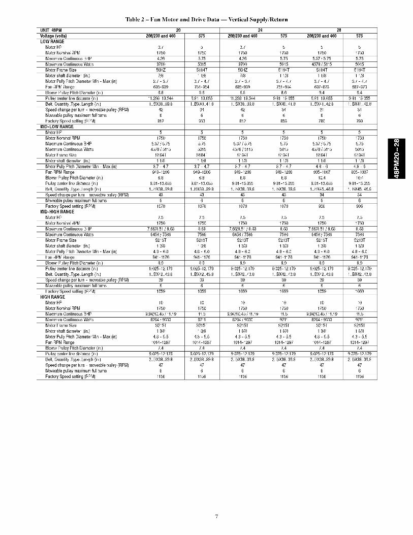
Table 2 - Fan Motor and Drive Data -- Vertical Supply/Return
UNIT 48PM 20 24 28
Voltage (volts) 208/230and 460 575 208/230and 460 575 208/230and 460 575LOW RANGE
MotorHP 3.7 5 3.7 5 5 5Motor NominalRPM 1750 1750 1750 1750 1750 1750
Maximum ContinuousBHP 4.26 5.75 4.26 5.75 5.37 / 5.75 5.75Maximum ContinuousWatts 3700 5015 3700 5015 4578 / 5115 5015Motor FrameSize 56HZ S184T 56HZ S184T S184T S184T
Motor shaft diameter (in.) 7/8 1 1/8 7/8 1 1/8 1 1/8 1 1/8Motor Puly PitchDiameterMin - Max (in) 2.7- 3.7 3.7 - 4.7 2.7 - 3.7 3.7 - 4.7 3.7 - 4.7 3.7 - 4.7
Fan RPMRange 685-939 751-954 685-939 751-954 687-873 687-873BlowerPulleyPitch Diameter(in.) 6.8 8.6 6.8 8.6 9.4 9.4
Pulleycenter linedistance(in.) 11.293-13.544 9.81-13.055 11.293-13.544 9.81-13.055 9.81-13.055 9.81-13.055Belt, Quantity_Type_Length(in.) 1..BX38..39.8 1..BX40..41.8 1..BX38..39.8 1..BX40..41.8 1..BX41..42.8 1..BX41..42.8Speedchangeper turn - moveablepulley(RPM) 42 34 42 34 31 31
Moveablepulley maximumfull turns 6 6 6 6 6 6Factory Speedsetting (RPM) 812 853 812 853 780 780
MID-LOW RANGE
Motor HP 5 5 5 5 5 5Motor NominalRPM 1750 1750 1750 1750 1750 1750
Maximum ContinuousBHP 5.37 / 5.75 5.75 5.37 / 5.75 5.75 5.37 / 5.75 5.75Maximum ContinuousWatts 4578 / 5115 5015 4578 / 5115 5015 4578 / 5115 5015Motor FrameSize S184T S184T S184T S184T S184T S184T
Motor shaft diameter (in.) 11/8 1 1/8 1 1/8 1 1/8 1 1/8 1 1/8Motor Pully PitchDiameterMin - Max (in) 3.7- 4.7 3.7 - 4.7 3.7 - 4.7 3.7 - 4.7 4.8 - 6 4.8 - 6
Fan RPMRange 949-1206 949-1206 949-1206 949-1206 805-1007 805-1007BlowerPulleyPitch Diameter(in.) 6.8 6.8 6.8 6.8 10.4 10.4
Pulleycenter linedistance(in.) 9.81-13.055 9.81-13.055 9.81-13.055 9.81-13.055 9.81-13.055 9.81-13.055Belt, Quantity_Type_Length(in.) 1..BX38..39.8 1..BX38..39.8 1..BX38..39.8 1..BX38..39.8 1..BX45..46.8 1..BX45..46.8Speedchangeper turn - moveablepulley(RPM) 43 43 43 43 34 34
Moveablepulley maximumfull turns 6 6 6 6 6 6Factory Speedsetting (RPM) 1078 1078 1078 1078 906 906
MID-HIGH RANGE
Motor HP 7.5 7.5 7.5 7.5 7.5 7.5Motor NominalRPM 1750 1750 1750 1750 1750 1750
Maximum ContinuousBHP 7.66/8.51/ 8.63 8.63 7.66/8.51/ 8.63 8.63 7.66/8.51/ 8.63 8.63Maximum ContinuousWatts 6458 / 7586 7586 6458 / 7586 7586 6458 / 7586 7586Motor FrameSize S213T S213T S213T S213T S213T S213T
Motor shaft diameter (in.) 13/8 1 3/8 13/8 13/8 13/8 13/8Motor Pully PitchDiameterMin - Max (in) 4.8- 6.0 4.8 - 6.0 4.8 - 6.0 4.8 - 6.0 4.8 - 6.0 4.8 - 6.0
Fan RPMRange 941-1176 941-1176 941-1176 941-1176 941-1176 941-1176BlowerPulleyPitch Diameter(in.) 8.9 8.9 8.9 8.9 8.9 8.9
Pulleycenter linedistance(in.) 9.025-12.179 9.025-12.179 9.025-12.179 9.025-12.179 9.025-12.179 9.025-12.179Belt, Quantity_Type_Length(in.) 1..BX42..43.8 1..BX42..43.8 1..BX42..43.8 1..BX42..43.8 1..BX42..43.8 1..BX42..43.8Speedchangeper turn - moveablepulley(RPM) 39 39 39 39 39 39
Moveablepulley maximumfull turns 6 6 6 6 6 6Factory Speedsetting (RPM) 1059 1059 1059 1059 1059 1059
HIGH RANGE
Motor HP 10 10 10 10 10 10Motor NominalRPM 1750 1750 1750 1750 1750 1750
Maximum ContinuousBHP 9.94/10.45/ 11.19 11.5 9.94/10.45 / 11.19 11.5 9.94/10.45 / 11.19 11.5Maximum ContinuousWatts 8284 / 9330 9711 8284 / 9330 9711 8284 / 9330 9711Motor FrameSize S215T S215T S215T S215T S215T S215T
Motor shaft diameter (in.) 13/8 1 3/8 13/8 13/8 13/8 13/8Motor Pully PitchDiameterMin - Max (in) 4.3- 5.5 4.3 - 5.5 4.3 - 5.5 4.3 - 5.5 4.3 - 5.5 4.3 - 5.5
Fan RPMRange 1014-1297 1014-1297 1014-1297 1014-1297 1014-1297 1014-1297BlowerPulleyPitch Diameter(in.) 7.4 7.4 7.4 7.4 7.4 7.4
Pulleycenter linedistance(in.) 9.025-12.179 9.025-12.179 9.025-12.179 9.025-12.179 9.025-12.179 9.025-12.179Belt, Quantity_Type_Length(in.) 2..BX38..39.8 2..BX38..39.8 2..BX38..39.8 2..BX38..39.8 2..BX38..39.8 2..BX38..39.8Speedchangeper turn - moveablepulley(RPM) 47 47 47 47 47 47
Moveablepulley maximumfull turns 6 6 6 6 6 6Factory Speedsetting (RPM) 1156 1156 1156 1156 1156 1156
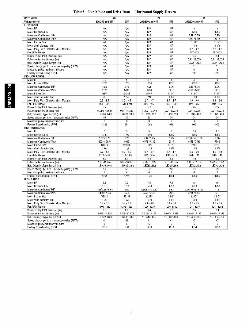
Table 3 - Fan Motor and Drive Data -- Horizontal Supply/Return
UNIT 48PM 20 24 28
Voltage (volts) 208/230and 460 575 208/230and 460 575 208/230and 460 575LOW RANGE
Motor HP N/A N/A N/A N/A 5 5
Motor NominalRPM N/A N/A N/A N/A 1750 1750Maximum ContinuousBHP N/A N/A N/A N/A 5.37/ 5.75 5.75Maximum ContinuousWatts N/A N/A N/A N/A 4578 / 5115 5015
Motor FrameSize N/A N/A N/A N/A S184T S184T
Motor shaft diameter (in.) N/A N/A N/A N/A 1 1/8 1 1/8Motor Puly PitchDiameterMin - Max (in) N/A N/A N/A N/A 3.7 - 4.7 3.7 - 4.7
Fan RPMRange N/A N/A N/A N/A 687-873 687-873BlowerPulleyPitch Diameter(in.) N/A N/A N/A N/A 9.4 9.4
Pulleycenter linedistance(in.) N/A N/A N/A N/A 9.81-13.055 9.81-13.055Belt, Quantity_Type_Length(in.) N/A N/A N/A N/A 1..BX41..42.8 1..BX41..42.8Speedchangeper turn - moveablepulley(RPM) N/A N/A N/A N/A 31 31
Moveablepulley maximumfull turns N/A N/A N/A N/A 6 6Factory Speedsetting (RPM) N/A N/A N/A N/A 780 780
MID-LOW RANGE
Motor HP 3.7 5 3.7 5 5 5Motor NominalRPM 1750 1750 1750 1750 1750 1750
Maximum ContinuousBHP 4.26 5.75 4.26 5.75 5.37/ 5.75 5.75Maximum ContinuousWatts 3700 5015 3700 5015 4578 / 5115 5015Motor FrameSize 56HZ S184T 56HZ S184T S184T S184T
Motor shaft diameter (in.) 7/8 1 1/8 7/8 1 1/8 1 1/8 1 1/8Motor Puly PitchDiameterMin - Max (in) 2.7 - 3.7 3.7 - 4.7 2.7 - 3.7 3.7 - 4.7 4.8 - 6.0 4.8 - 6.0
Fan RPMRange 896-1227 873-1108 896-1227 873-1108 805-1007 805-1007BlowerPulleyPitch Diameter(in.) 5.2 7.4 5.2 7.4 10.4 10.4
Pulleycenter linedistance(in.) 11.293-13.544 9.81-13.055 11.293-13.544 9.81-13.055 9.81-13.055 9.81-13.055Belt, Quantity_Type_Length(in.) 1..BX35..36.8 1..BX38..39.8 1..BX35..36.8 1..BX38..39.8 1..BX45..46.8 1..BX45..46.8Speedchangeper turn - moveablepulley(RPM) 55 39 55 39 34 34
Moveablepulley maximumfull turns 6 6 6 6 6 6Factory Speedsetting (RPM) 1062 991 1062 991 906 906
MID-HIGH RANGE
Motor HP 5 5 5 5 7.5 7.5Motor NominalRPM 1750 1750 1750 1750 1750 1750
Maximum ContinuousBHP 5.37/ 5.75 5.75 5.37 / 5.75 5.75 7.66/8.51/ 8.63 8.63Maximum ContinuousWatts 4578 / 5115 5015 4578 / 5115 5015 6458/ 7586 7586Motor FrameSize S184T S184T S184T S184T S213T S213T
Motor shaft diameter (in.) 1 1/8 1 1/8 1 1/8 1 1/8 1 3/8 1 3/8Motor Pully PitchDiameterMin - Max (in) 3.7 - 4.7 3.7 - 4.7 3.7 - 4.7 3.7 - 4.7 4.8 - 6.0 4.8 - 6.0
Fan RPMRange 1113-1414 1113-1414 1113-1414 1113-1414 941-1176 941-1176BlowerPulleyPitch Diameter(in.) 5.8 5.8 5.8 5.8 8.9 8.9
Pulleycenter linedistance(in.) 9.81-13.055 9.81-13.055 9.81-13.055 9.81-13.055 9.025-12.179 9.025-12.179Belt, Quantity_Type_Length(in.) 1..BX35..36.8 1..BX35..36.8 1..BX35..36.8 1..BX35..36.8 1..BX42..43.8 1..BX42..43.8Speedchangeper turn - moveablepulley(RPM) 50 50 50 50 39 39
Moveablepulley maximumfull turns 6 6 6 6 6 6Factory Speedsetting (RPM) 1264 1264 1264 1264 1059 1059
HIGH RANGE
Motor HP 7.5 7.5 7.5 7.5 10 10Motor NominalRPM 1750 1750 1750 1750 1750 1750
Maximum ContinuousBHP 7.66/8.51/ 8.63 8.63 7.66/8.51/ 8.63 8.63 9.94/10.45/ 11.19 11.5Maximum ContinuousWatts 6458 / 7586 7586 6458 / 7586 7586 8284/ 9330 9711Motor FrameSize S213T S213T S213T S213T S215T S215T
Motor shaft diameter (in.) 1 3/8 13/8 13/8 1 3/8 1 3/8 1 3/8Motor Pully PitchDiameterMin - Max (in) 5.4 - 6.6 5.4 - 6.6 5.4 - 6.6 5.4 - 6.6 4.3 - 5.5 4.3 - 5.5
Fan RPMRange 1096-1339 1096-1339 1096-1339 1096-1339 1014-1297 1011-1293BlowerPulleyPitch Diameter(in.) 8.6 8.6 8.6 8.6 7.4 7.4
Pulleycenter linedistance(in.) 9.025-12.179 9.025-12.179 9.025-12.179 9.025-12.179 9.025-12.179 9.025-12.179Belt, Quantity_Type_Length(in.) 1..BX42..43.8 1..BX42..43.8 1..BX42..43.8 1..BX42..43.8 1..BX38..39.8 1..BX38..39.8Speedchangeper turn - moveablepulley(RPM) 41 41 41 41 47 47
Moveablepulley maximumfull turns 6 6 6 6 6 6Factory Speedsetting (RPM) 1218 1218 1218 1218 1156 1156
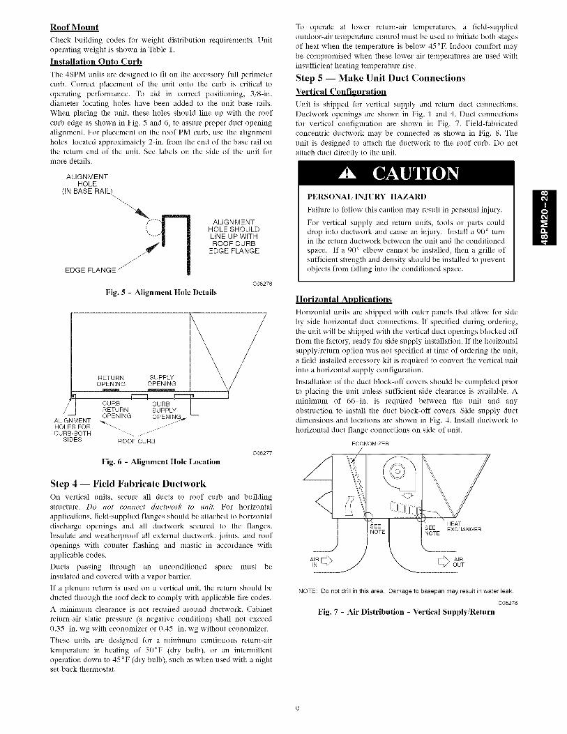
Roof Mount
Check building codes for weight distribution requirements, Unitoperating weight is shown in Table 1,
Installation Onto Curb
The 48PM units are designed to fit on the accessory full perimeter
curb. Correct placement of the unit onto the curb is critical to
operating performance. To aid in correct positioning, 3/8-in.
diameter locating holes have been added to the unit base rails.
When placing the unit, these holes should line up with the roof
curb edge as shown in Fig. 5 and 6, to assure proper duct opening
alignment. For placement on the roof PM curb, use the alignment
holes located approximately 2-in. from the end of the base rail onthe return end of the unit. See labels on the side of the unit for
more details.
ALIGNMENTHOLE
(IN BASE
EDGE FLANGE _
ALIGNMENTHOLE SHOULDLINE UP WITHROOF CURB
EDGE FLANGE
C06276
Fig. 5 - Alignment Hole Details
RETURN SUPPLYOPENING OPENING
CURB CURBRETURN SUPPLY LOPENING
ALIGNMENT _,.HOLES FORCURB-BOTH _. jJ
SIDES ROOFCURB
Fig. 6 - Alignment Hole Location
C06277
Step 4 -- Field Fabricate Ductwork
On vertical units, secure all ducts to roof curb and buildingstructure. Do not connect ductwork to unit. For horizontal
applications, field-supplied flanges should be attached to horizontal
discharge openings and all ductwork secured to the flanges.
Insulate and weatherproof all external ductwork, joints, and roof
openings with counter flashing and mastic in accordance with
applicable codes.
Ducts passing through an unconditioned space must be
insulated and covered with a vapor barrier.
If a plenum return is used on a vertical unit, the return should be
ducted through the roof deck to comply with applicable fire codes.
A minimum clearance is not required around ductwork. Cabinet
return-air static pressure (a negative condition) shall not exceed
0.35-in. wg with econonfizer or 0.45-in. wg without econonfizer.
These units are designed for a minimum continuous return-air
temperature in heating of 50°F (dry bulb), or an internfittent
operation down to 45°F (dry bulb), such as when used with a nightset-back thermostat.
To operate at lower return-air temperatures, a field-supplied
outdoor-air temperature control nmst be used to initiate both stages
of heat when the temperature is below 45°F. Indoor comfort may
be compronfised when these lower air temperatures are used with
insufficient heating temperature rise.
Step 5 -- Make Unit Duct Connections
Vertical Configuration
Unit is shipped for vertical supply and return duct connections.
Ductwork openings are shown in Fig. 1 and 4. Duct connections
for vertical configuration are shown in Fig. 7. Field-fabricated
concentric ductwork may be connected as shown in Fig. 8. The
unit is designed to attach the ductwork to the roof curb. Do not
attach duct directly to the unit.
PERSONAL INJURY HAZARD
Failure to follow this caution may result in personal injury.
For vertical supply and return units, tools or parts coulddrop into ductwork and cause an injury. Install a 90 ° turnin the return ductwork between the unit and the conditioned
space. If a 90 ° elbow cannot be installed, then a grille of
sufficient strength and density should be installed to prevent
objects from falling into the conditioned space.
Horizontal Applications
Horizontal units are shipped with outer panels that allow for side
by side horizontal duct connections. If specified during ordering,
the unit will be shipped with the vertical duct openings blocked off
from the factory, ready for side supply installation. If the horizontal
supply/return option was not specified at time of ordering the unit,
a field-installed accessory kit is required to convert the vertical unit
into a horizontal supply configuration.
Installation of the duct block-off covers should be completed prior
to placing the unit unless sufficient side clearance is available. A
nfininmm of 66-in. is required between the unit and any
obstruction to install the duct block-off covers. Side supply duct
dimensions and locations are shown in Fig. 4. Install ductwork to
horizontal duct flange connections on side of unit.
ECONOMIZER
HEATEXCHANGER
NOTE: Do not drill in this area. Damageto basepanmay result in water leak.
C06278
Fig. 7 - Air Distribution - Vertical Supply/Return
H
ECONOMIZER
HEATSEE EXCHANGER
AIR OUT AIR IN AIR OUT
NOTE: Do not drill in this area. Damageto basepanmay result in water leak.
C06279
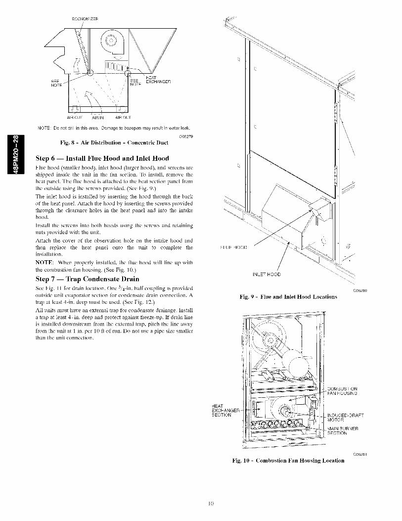
Fig. 8 - Air Distribution - Concentric Duct
Step 6 -- Install Flue Hood and Inlet Hood
Flue hood (smaller hood), inlet hood (larger hood), and screens areshipped inside the unit in the fan section. To install, remove theheat panel. The flue hood is attached to the heat section panel from
the outside using the screws provided. (See Fig. 9.)
The inlet hood is installed by inserting the hood through the back
of the heat panel. Attach the hood by inserting the screws provided
through the clearance holes in the heat panel and into the intakehood.
Install the screens into both hoods using the screws and retaining
nuts provided with the unit.
Attach the cover of the observation hole on the intake hood and
then replace the heat panel onto the unit to complete theinstallation.
NOTE: When properly installed, the flue hood will line up with
the combustion fan housing. (See Fig. 10.)
Step 7 -- Trap Condensate Drain
See Fig. 11 for drain location. One 3/4-in. half coupling is provided
outside unit evaporator section for condensate drain connection. A
trap at least 4-in. deep must be used. (See Fig. 12.)
All units must have an external trap for condensate drainage. Install
a trap at least 4-in. deep and protect against freeze-up. If drain line
is installed downstream from the external trap, pitch the line away
from the unit at 1 in. per 10 ft of run. Do not use a pipe size smallerthan the unit connection.
FLUE HOOD
INLET HOOD
Fig. 9 - Flue and Inlet Hood Locations
HEATEXCHANGER-SECTION
C06280
COMBUSTION• FAN HOUSING
INDUCED-DRAFTMOTOR
MAIN BURNERSECTION
C06281
Fig. 10 - Combustion Fan Housing Location
10

-DAMPER MOTORACCESS COVER
DRAIN CONNECTION
4,SUPPLY
AIR
5-1/4[132]
47-1/2[t2o8]
1,RETURN
AIR
Fig. 11 - Condensate Drain Details
C06282
1ONFETaN() FPEIRNE \ Ep_AI_CLE_t I ' L_
I ] __,_) DRAIN PLUG _;:
tSEE
NOTE
._.ROOFCURB
NOTE: Trap should be deep enough to offset maximumunit static differenceA 4-in. trap is recommended.
C06291
Fig. 12 - Condensate Drain Piping Details
MANUALSHUTOFF(FIELDSUPPLIED) rT1
SUPPLY
PRESSURE TAP(1/8" NPT PLUG)
UNIT
_---- SEDIMENTTRAPuNION
C06236
Fig. 13 - Field Gas Piping
Step 8 -- Install Gas Piping
Unit is equipped for use with natural gas. Refer to local building
codes, or in the absence of local codes, to ANSI Z223.1-1atest year
and addendum Z223.1A-latest year entitled NFGC. In Canada,installation must be in accordance with the CANI.BI49.1 and
CANI.BI49.2 installation codes for gas burning appliances.
Support gas piping. For example, a 3/4-in. gas pipe nmst have one
field-fabricated support beam every 8 ft. Therefore, an 18-ft long
gas pipe would have a minimum of 3 support beams.
Install field-supplied manual gas shutoff valve with a 1/8-in. NPT
pressure tap for test gauge connection at unit. The pressure tap is
located on the gas manifold, adjacent to the gas valve. Field gas
piping must include sediment trap and union. (See Fig. 13.)
FIRE, EXPLOSION HAZARD
Failure to follow this warning could result in personal
iniury or death.
Do not pressure test gas supply while connected to unit.
Always disconnect union before servicing. High pressures
can cause gas valve damage resulting in a hazardouscondition.
IMPORTANT: Natural gas pressure at unit gas connection must
not be less than 5.5-in. wg or greater than 13.0-in. wg.
Size gas-supply piping for 0.5-in. wg maximum pressure drop. Do
not use supply pipe smaller than unit gas connection.
Step 9 -- Orifice Change
This unit is factory assembled for heating operation using natural
gas at an elevation from sea level to 2000 ft. This unit uses orifice
type LH32RFnnn, where "nnn" indicates the orifice size based ondrill size diameter in thousands of an inch.
High Elevation (Above 2000 It)
Use accessory high altitude kit when installing this unit at an
elevation of 2000 to 7000 ft. For elevations above 7000 ft, refer to
Table 4 to identify the correct orifice size for the elevation. See
Table 5 for the number of orifices required for each unit size.
Purchase these orifices from your local Carrier dealer. Follow
instructions in accessory Installation Instructions to install thecorrect orifices.
Table 4 - Altitude Compensation*
ELEVATIONLow Med.
(ft) Heat Heat
0-1,999 29 30
2,000 29 30
3,000 30 31
4,000 30 31
5,000 30 31
8,000 30 31
7,000 31 32
8,000 31 32
9,000 31 32
10,000 32 33
NATURAL GAS ORIFICEt
High Heat High Heat
(8 Cell) (8 Cell)
29 29
29 29
30 30
30 30
30 30
30 30
31 31
31 31
31 31
32 32
*As the height above sea level increases, there is less oxygen per cubic ft.of air. Therefore, heat input rate should be reduced at higher altitudes.Includes a 4% input reduction per each 1000 if.Orifices available throughyour Carrier dealer.
Table 5 - Orifice Quantity
ORIFICEUNIT
QUANTITY
Low Heat (48PMD/L) 5
Medium Heat (48PME/M) 8
High Heat (48PMF/N) 8
Conversion to LP (Liquid Propane) Gas
Use accessory LP gas conversion kit when converting this unit for
use with LP fuel usage for elevations up to 7000 ft. For elevations
above 7000 ft, refer to Table 6 to identify the correct orifice size for
the elevation. See Table 5 for the number of orifices required for
each unit size. Purchase these orifices from your local Carrier
dealer. Follow instructions in accessory Installation Instructions to
install the correct orifices.
11
H
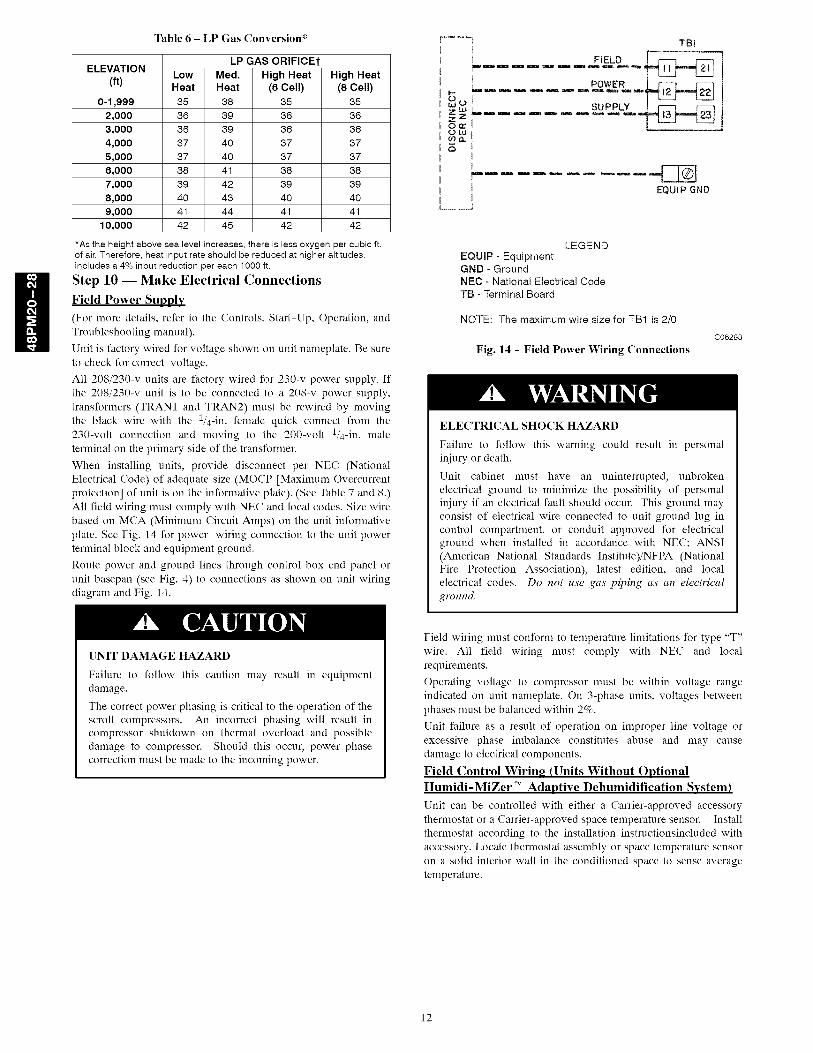
Table 6 - LP Gas Conversion*
LP GAS ORIFICEtELEVATION
(ft) Low Med. High HeatHeat Heat (8 Cell)
0-1,999 35 38 35
2,000 36 39 36
3,000 36 39 36
4,000 37 40 37
5,000 37 40 37
8,000 38 41 38
7,000 39 42 39
8,000 40 43 40
9,000 41 44 41
10,000 42 45 42
High Heat
(8 Cell)
35
36
36
37
37
38
39
40
41
42
*As the height above sea level increases, there is less oxygen per cubic ft.of air. Therefore, heat input rate should be reduced at higher altitudes.Includes a 4% input reduction per each 1000 ft.
Step 10 -- Make Electrical Connections
Field Power Supply
(For more details, refer to the Controls, Start-Up, Operation, andTroubleshooting manual).
Unit is factory wired for voltage shown on unit nameplate. Be sureto check for correct voltage.
All 208/230-v units are factory wired for 230-v power supply. Ifthe 208/230-v unit is to be connected to a 208-v power supply,transformers (TRANI and TRAN2) must be rewired by movingthe black wire with the 1/4-in. female quick connect from the230-volt connection and moving to the 200-volt 1/4-in. maleterminal on the primary side of the transformer.
When installing units, provide disconnect per NEC (NationalElectrical Code) of adequate size (MOCP [Maximum Overcurrentprotection] of unit is on the informative plate). (See Table 7 and 8.)All field wiring must comply with NEC and local codes. Size wirebased on MCA (Minimum Circuit Amps) on the unit informativeplate. See Fig. 14 for power wiring connection to the unit powerterminal block and equipment ground.
Route power and ground lines through control box end panel orunit basepan (see Fig. 4) to connections as shown on unit wiringdiagram and Fig. 14.
.... ] TBI
[ FIELD [ _
L ....... POW£..i
zw
ow
EQUIP GND
LEGENDEQUIP - EquipmentGND - GroundNEC - National Electrical CodeTB - Terminal Board
NOTE: The maximum wire size for TB1 is 2/0
Fig. 14 - Field Power Wiring Connections
C06293
ELECTRICAL SHOCK HAZARD
Failure to follow this warning could result in personaliniury or death.
Unit cabinet must have an uninterrupted, unbrokenelectrical ground to minimize the possibility of personaliniury if an electrical fault should occur. This ground mayconsist of electrical wire connected to unit ground lug incontrol compartment, or conduit approved for electricalground when installed in accordance with NEC; ANSI(American National Standards Institute)/NFPA (NationalFire Protection Association), latest edition, and localelectrical codes. Do not use gas piping as an electricalground.
UNIT DAMAGE HAZARD
Failure to follow this caution may result in equipmentdamage.
The correct power phasing is critical to the operation of thescroll compressors. An incorrect phasing will result incompressor shutdown on thermal overload and possibledamage to compressor. Should this occur, power phasecorrection must be made to the incoming power.
Field wiring must conform to temperature limitations for type "T"wire. All field wiring must comply with NEC and localrequirements.
Operating voltage to compressor must be within voltage rangeindicated on unit nameplate. On 3-phase units, voltages betweenphases must be balanced within 2%.
Unit failure as a result of operation on improper line voltage orexcessive phase imbalance constitutes abuse and may causedamage to electrical components.
Field Control Wiring (Units Without OptionalHumidi-MiZer TM Adaptive Dehumidification System)
Unit can be controlled with either a Carrier-approved accessorythermostat or a Carrier-approved space temperature sensor. Installthermostat according to the installation instructionsincluded withaccessory. Locate thermostat assembly or space temperature sensoron a solid interior wall in the conditioned space to sense averagetemperature.
12
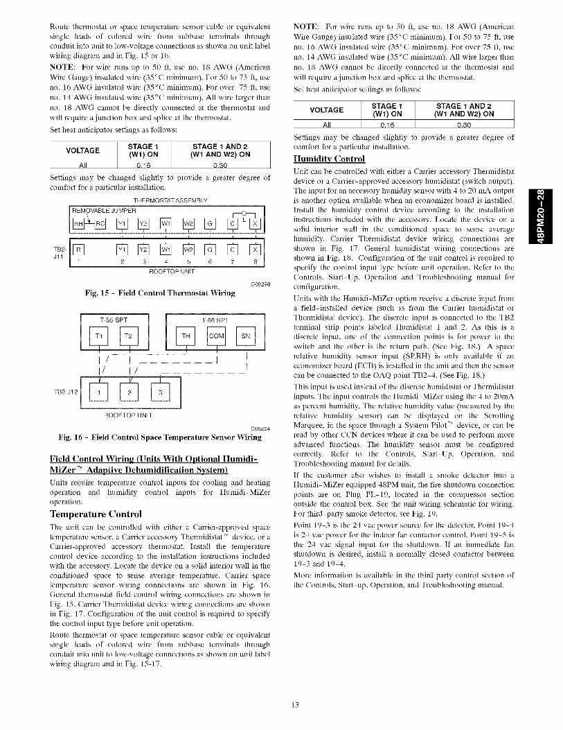
Routethermostat or space temperature sensor cable or equivalent
single leads of colored wire from subbase terminals through
conduit into unit to low-voltage connections as shown on unit label
wiring diagram and in Fig. 15 or 16.
NOTE: For wire runs up to 50 fl, use no. 18 AWG (American
Wire Gauge) insulated wire (35°C n_ininmn_). For 50 to 75 fl, use
no. 16 AWG insulated wire (35°C n_ininmn_). For over 75 fl, use
no. 14 AWG insulated wire (35°C n_ininmn_). All wire larger than
no. 18 AWG cannot be directly connected at the thermostat and
will require a junction box and splice at the thermostat.
Set heat anticipator settings as follows:
STAGE 1 STAGE 1 AND 2VOLTAGE(W1) ON (W1 AND W2) ON
All 0.15 0.30
Settings may be changed slightly to provide a greater degree of
comfort for a particular installation.
THERMOSTAT ASSEMBLY
JUMPER
--4
TB2-[ 1[_Jll [_ [_ [_ @ [] [][_2 3 4 5 6 7 8
ROOFTOP UNIT
C06298
Fig. 15 - Field Control Thermostat Wiring
TB2-J12
[ lI/ I l lI1 I/ t
ROOFTOP UNIT
C06294
Fig. 16 - Field Control Space Temperature Sensor Wiring
Field Control Wiring (Units With Optional Humidi-MiZer TM Adaptive Dehumidification System)
Units require temperature control inputs for cooling and heating
operation and humidity control inputs for Humidi-MiZer
operation.
Temperature Control
The unit can be controlled with either a Carrier-approved space
temperature sensor, a Carrier accessory Thermidistat T,, device, or aCarrier-approved accessory thermostat. Install the temperature
control device according to the installation instructions included
with the accessory. Locate the device on a solid interior wall in the
conditioned space to sense average temperature. Carrier space
temperature sensor wiring connections are shown in Fig. 16.
General thermostat field control wiring connections are shown in
Fig. 15. Carrier Thermidistat device wiring connections are shown
in Fig. 17. Configuration of the unit control is required to specify
the control input type before unit operation.
Route thermostat or space temperature sensor cable or equivalent
single leads of colored wire from subbase terminals through
conduit into unit to low-voltage connections as shown on unit label
wiring diagram and in Fig. 15-17.
NOTE: For wire runs up to 50 fl, use no. 18 AWG (American
Wire Gauge) insulated wire (35°C n_ininmm). For 50 to 75 ft, use
no. 16 AWG insulated wire (35°C n_ininmm). For over 75 ft, use
no. 14 AWG insulated wire (35°C n_ininmm). All wire larger than
no. 18 AWG cannot be directly connected at the thermostat and
will require a junction box and splice at the thermostat.
Set heat anticipator settings as follows:
STAGE 1 STAGE 1 AND 2VOLTAGE(W1) ON (W1 AND W2) ON
All 0.15 0.30
Settings may be changed slightly to provide a greater degree of
comfort for a particular installation.
Humidity Control
Unit can be controlled with either a Carrier accessory Thermidistat
device or a Carrier-approved accessory humidistat (switch output).The input for an accessory humidity sensor with 4 to 20 mA output
is another option available when an economizer board is installed.
Install the humidity control device according to the installation
instructions included with the accessory. Locate the device on a
solid interior wall in the conditioned space to sense average
humidity. Carrier Thermidistat device wiring connections are
shown in Fig. 17. General humidistat wiring connections are
shown in Fig. 18. Configuration of the unit control is required to
specify the control input type before unit operation. Refer to the
Controls, Start-Up, Operation and Troubleshooting manual for
configuration.
Units with the Humidi-MiZer option receive a discrete input from
a field-installed device (such as from the Carrier humidistat or
Thermidistat device). The discrete input is connected to the TB2
terminal strip points labeled Humidistat 1 and 2. As this is a
discrete input, one of the connection points is for power to the
switch and the other is the return path. (See Fig. 18.) A space
relative humidity sensor input (SP.RH) is only available if an
economizer board (ECB) is installed in the unit and then the sensor
can be connected to the OAQ point TB2-4. (See Fig. 18.)
This input is used instead of the discrete humidistat or Thermidistat
inputs. The input controls the Humidi-MiZer using the 4 to 20mA
as percent humidity. The relative humidity value (measured by the
relative humidity sensor) can be displayed on the Scrolling
Marquee, in the space through a System Pilot '_ device, or can be
read by other CCN devices where it can be used to perform more
advanced functions. The humidity sensor nmst be configured
correctly. Refer to the Controls, Start-Up, Operation, and
Troubleshooting manual for details.
If the customer also wishes to install a smoke detector into a
Humidi-MiZer equipped 48PM unit, the fire shutdown connection
points are on Plug PL-19, located in the compressor section
outside the control box. See the unit wiring schematic for wiring.
For third-party smoke detector, see Fig. 19.
Point 19-3 is the 24 vac power source for the detector. Point 19-4
is 24 vac power for the indoor fan contactor control. Point 19-5 is
the 24 vac signal input for the shutdown. If an immediate fan
shutdown is desired, install a normally closed contactor between19-3 and 19-4.
More information is available in the third party control section of
the Controls, Start-up, Operation, and Troubleshooting manual.
13
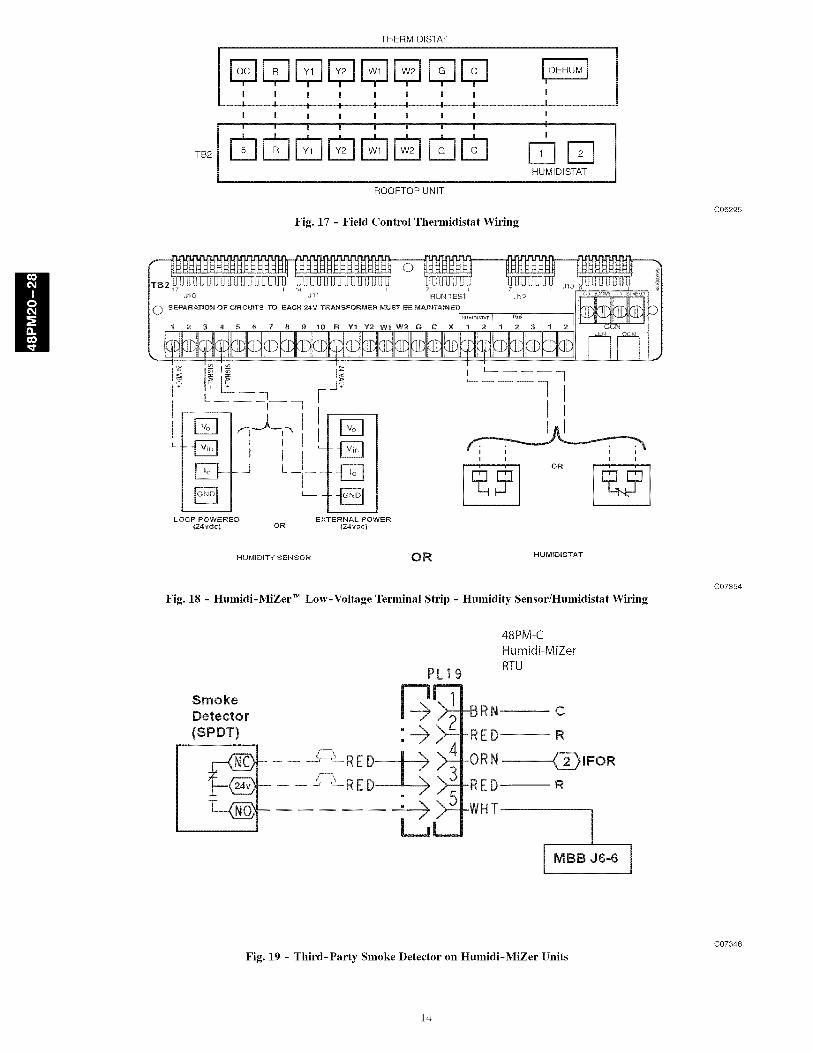
TB2
THERMIDISTAT
- DDDDD DI : : ' : : ', , , ',
| | ! ! | ! ! I |
@nrqrqrarmrmrq ri mHUMIDISTAT
ROOFTOP UNIT
Fig. 17 - Field Control Thermidistat Wiring
C06295
i ]tl
tl
i i i iOR _ i
N UMIDI"P'I SENSOR OR HUMIDtSTAT
Fig. 18 - Humidi-MiZer TM Low-Voltage Terminal Strip - Humidity Sensor/Humidistat Wiring
C07354
PL19
Smoke F-_ i'_Detector
-- i i _!--REI_
_- RED_ X
-BRN
-RED
-ORN --
-RED--
-WHT
48PM-CHumidi-MiZer
RTU
C
R
_IFOR
R
!
Fig. 19 - Third-Party Smoke Detector on Humidi-MiZer Units
C07346
14
NOMINAL VOLTAGE48PM VOLTAGE RANGE
S_ZE (3 Ph,60 Min MaxHz)
208/230 187 253
2O460 414 506
575 518 633
208/230 187 253
24460 414 506
575 518 633
2081230 187 253
28 460 414 506
575 518 633
*See notes and legend on page 17.
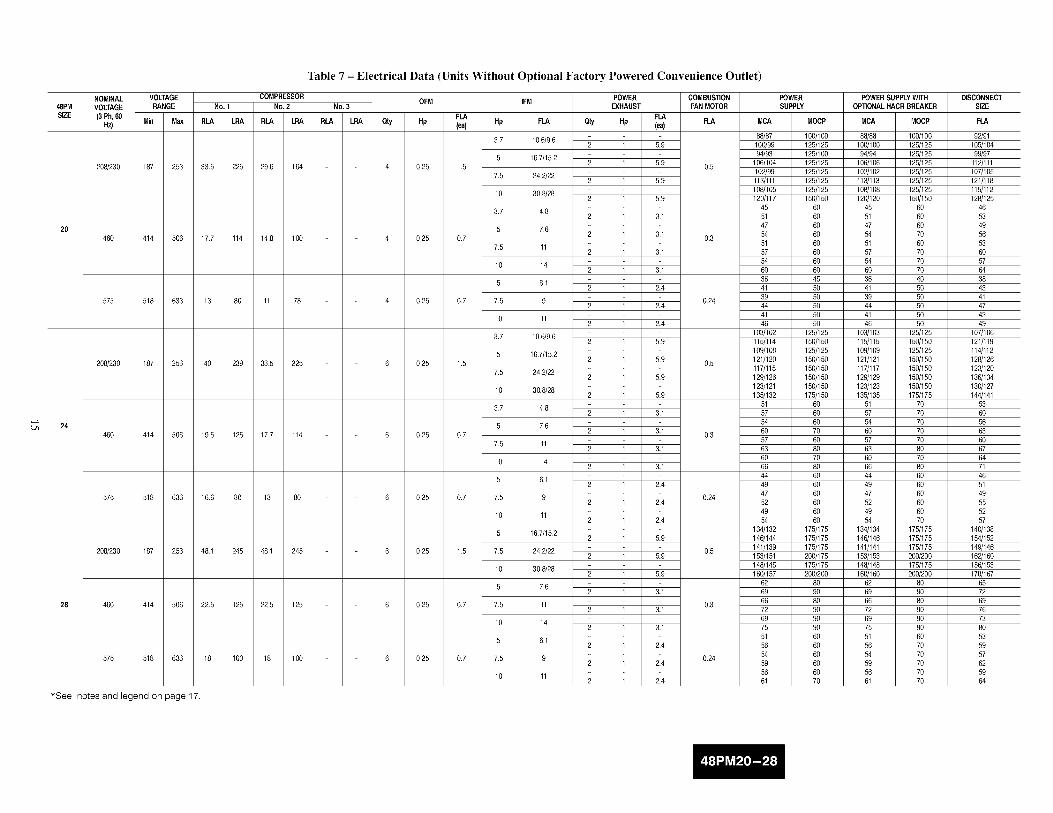
Table 7 - Electrical Data (Units Without Optional Factory Powered Convenience Outlet)
No. 1
RLA LRA
COMPRESSORNo.2
RLA LRA
33.5 225 29.6 164
17.7 114 14.8 100
13 80 11 78
40 239 33.5 225
19.5 125 17.7 114
16.6 80 13 80
48.1 245 48.1 245
22.5 125 22.5 125
18 100 18 100
No. 3
RLA LRA Qty
OFM
FLAHp (_)
0.25 1.5
0.25 0.7
0.25 0.7
0.25 1.5
0.25 0.7
0.25 0.7
0.25 1.5
0.25 0.7
0.25 0.7
IFM POWER COMBUSTIONEXHAUST FAN MOTOR
FLAHp FLA City Hp (ea) FLA
3.7 10.6/9.62 1 5.9
5 16.7/15.22 1 5.9 0.5
7.5 24.2/222 1 5.9
10 30.8/282 1 5.9
3.7 4.82 1 3,1
5 7.62 1 3,1 0.3
7.5 112 1 3,1
10 142 1 3,1
5 6.12 1 2.4
7.5 9 0.242 1 2.4
10 112 1 2.4
3.7 10.6/9.62 1 5.9
5 16.7/15.22 1 5.9 0.5
7.5 24.2/222 1 5.9
10 30.8/282 1 5.9
3.7 4.82 1 3,1
5 7.62 1 3,1 0.3
7.5 112 1 3,1
10 142 1 3,1
5 6.12 1 2.4
7.5 9 0.242 1 2.4
10 112 1 2.4
5 16.7/15.22 1 5.9
7.5 24.2/22 0.52 1 5.9
10 30.8/282 1 5.9
5 7.62 1 3,1
7.5 11 0.32 1 3,1
10 142 1 3,1
5 6.12 1 2.4
7.5 9 0.242 1 2.4
10 112 1 2.4
rvlCA
88/8710019994193
106/104102/99113/111108/1051201117
455147545157546O364139444146
103/102115/114109/108121/120117/115129/126123/121135/132
5157546O57636O66444947524954
134/1321461144141/139153/151148/145160/157
626966726975515654595661
POWER POWERSUPPLYWffHSUPPLY OPTIONALHACRBREAKER
MOCP MCA MOCP
100/100 88/88 100/100125/125 100/100 125/125125/100 94/94 125/125125/125 106/106 125/125125/125 102/102 125/125125/125 113/113 125/125125/125 108/108 125/125150/150 120/120 150/150
60 45 6060 51 6060 47 6060 54 7060 51 6060 57 7060 54 7060 60 7045 36 4050 41 5050 39 505O 44 5O50 41 5050 46 50
125/125 103/103 125/125150/150 115/115 150/150125/125 109/109 125/125150/150 121/121 150/150150/150 117/117 150/150150/150 129/129 150/150150/150 123/123 150/150175/150 135/135 175/175
60 51 7060 57 7060 54 7070 60 7060 57 7080 63 8070 60 7080 66 8060 44 6060 49 6060 47 6060 52 6060 49 6060 54 70
175/175 134/134 175/175175/175 146/146 175/175175/175 141/141 175/175200/175 153/153 200/200175/175 148/148 175/175200/200 160/160 200/200
80 62 8090 69 9080 66 8090 72 9090 69 9090 75 9060 51 6060 56 7060 54 7060 59 7060 56 7070 61 70
DISCONNECTSIZE
FLA
92191105/10499/97
112/111107/105121/118115/112128/125
46534956536O5764384341474349
107/106121/119114/112128/126123/120136/134130/127144/141
536O56636O676471465149555257
140/138154/152149/146162/160156/153170/167
65726976738O535957625964

48PMS_E
NOMINAL VOLTAGERANGEVOLTAGE(3Ph,
60 Hz)Min Max
208/230 187 253
460 414 506
575 518 633
208/230 187 253
460 414 506
575 518 633
208/230 187 253
460 414 506
575 518 633
*See notes and legend on page 17.
Table 8 - Electrical Data (Units With Optional Powered Convenience Outlet)
COMPRESSOROFM
NO.1 NO.2 NO.3
RLA LRA RLA LRA RLA LRA Qty Hp
33.5 225 29.6 164
17.7 114 14.8 100
13 80 11 78
40 239 33.5 225
19.5 125 17.7 114
16.6 80 13 80
48.1 245 48.1 245
22.5 125 22.5 125
18 100 18 100
POWER COMBUSTION POWER POWERSUPPLYWITHIRVi EXHAUST FANMOTOR SUPPLY OPTIONALHACR
BREAKER
FLA FLA(ea) Hp FLA Qty Hp (ea) FLA MCA MOCP MCA MOCP
3.7 10.6/9.6 93/92 100/100 93/93 125/1252 1 5.9 105/104 125/125 105/105 125/125
5 16.7/15.2 99/98 125/125 99/99 125/1254 0.25 1.5 2 1 5.9 0.5 111/109 125/125 111/111 125/125
7.5 24.2/22 107/104 125/125 107/107 125/1252 1 5.9 118/116 150/125 118/118 150/150
10 30.8/28 113/110 125/125 113/113 125/1252 1 5.9 125/122 150/150 125/125 150/150
3.7 4.8 48 60 48 602 1 3,1 54 60 54 70
5 7.6 50 60 50 604 0.25 0.7 2 1 3,1 0.3 57 60 57 70
7.5 11 54 60 54 702 1 3,1 60 60 60 70
10 14 57 60 57 702 1 3,1 63 80 63 80
5 6.1 39 50 39 502 1 2.4 44 50 44 50
4 0.25 0.7 7.5 9 0.24 42 50 42 502 1 2.4 47 50 47 50
10 11 44 50 44 502 1 2.4 49 60 49 60
3.7 10.6/9.6 108/107 125/125 108/108 125/1252 1 5.9 120/119 150/150 120/120 150/150
5 16.7/15.2 114/113 150/150 114/114 150/1506 0.25 1.5 2 1 5.9 0.5 126/125 150/150 126/126 150/150
7.5 24.2/22 122/120 150/150 122/122 150/1502 1 5.9 134/131 150/150 134/134 150/150
10 30.8/28 128/126 150/150 128/128 150/1502 1 5.9 140/137 175/175 140/140 175/175
3.7 4.8 54 60 54 702 1 3,1 60 70 60 70
5 7.6 57 60 57 706 0.25 0.7 2 1 3,1 0.3 63 80 63 80
7.5 11 60 70 60 702 1 3,1 66 80 66 80
10 14 63 80 63 802 1 3,1 69 80 69 80
5 6.1 47 60 47 602 1 2.4 52 60 52 60
6 0.25 0.7 7.5 9 0.24 50 60 50 602 1 2.4 55 60 55 70
10 11 52 60 52 602 1 2.4 57 60 57 70
5 16.7/15.2 139/137 175/175 139/139 175/1752 1 5.9 151/149 175/175 151/151 175/175
6 0.25 1.5 7.5 24.2/22 0.5 146/144 175/175 146/146 175/1752 1 5.9 158/156 200/200 158/158 200/200
10 30.8/28 153/150 200/175 153/153 200/2002 1 5.9 165/162 200/200 165/165 200/200
5 7.6 65 80 65 802 1 3,1 72 90 72 90
6 0.25 0.7 7.5 11 0.3 69 90 69 902 1 3,1 75 90 75 90
10 14 72 90 72 902 1 3,1 78 100 78 100
5 6.1 54 60 54 702 1 2.4 59 60 59 70
6 0.25 0.7 7.5 9 0.24 57 60 57 702 1 2.4 62 70 62 70
10 11 59 60 59 702 1 2.4 64 80 64 80
DISCONNECTSt_.E
FLA
97/96111/110104/103118/116113/111127/124121/117134/131
5O57536O57646O674147455O4752
113/112126/125120/118133/132128/126142/139136/133150/146
57646O676471677449555358556O
146/144160/158155/152168/166162/159176/173
6976738O768357626O666268

LEGENDFLA- FullLoadAmpsHACR- Heating,AirConditioningandRefrigerationIFM- Indoor(Evaporator)FanMotorLRA- LockedRotorAmpsMCA- MinimumCircuitAmpsMOCP- MaximumOvercurrentProtectionNEC- NationalElectricalCodeOFM- Outdoor-FanMotorRLA RatedLoadAmps
*Fuse or HACR circuit breaker
NOTES:
1, In compliance with NEC requirements for muItimotor and combination load equipment (refer to NEC Articles 430 and 440), the overcurrent
protective device for the unit shaII be fuse or HACR breaker,
2. Unbalanced 3-Phase SupplyVoltage
Never operate a motor where a phase imbalance in supply voltage is greater than 2%. Use the following formula to determine the percent-
age of voltage imbalance.
% Vottage Imbalance = lOOxmax voltage deviation from average voltage
average voltage
Example: Supply voltage is 460-3-60
AB = 452 v
BC = 464v
AC = 455 v
Average Voltage = 452 + 464 + 4553
_ 13713
- 457
Determine maximum deviation from average voltage,
(AB) 457- 452 = 5 v
(BC) 464 457 = 7 v
(AC)457 455 = 2v
Maximucq deviation is 7 v.
Determine percent of voltage imbalance.
7% Voltage Imbalance - 100 x
457
- 1 _53%
This amount of phase imbalance is satisfactory as it is below the maximum allowable 2%.
IMPORTANT: If the supply voItage phase imbaIance is more than 2%, contact your _ocaI eIectric utility company immediateIy,
3, The convenience outlet full Ioad amps (FLA) are 5,, 3, and 3 for 208/230, 460, 575-V units, respectiveIy,

Step 11 -- Install Outdoor Air Hood
Perform the following procedure to install the outdoor-air hood onunits equipped with an economizer, two-position damper, ormanual outdoor air damper:
1. Remove blank panel from return end of unit (hood section).Save the screws. See Fig. 20 for shipping location ofcomponents.
2. Hood sides are fastened to sides of outdoor air opening.
Remove the hood sides and save the screws (3 each side).
3. Remove the bracket holding the bottom half of the hood inthe shipping position. Remove the hood bottom half andfilters (or manual dampers on units so equipped) fromoutdoor section.
HOOD HOOD TOP
HOOD TOP SIDE (BOTTOM HALF)
HOODSIDE
RETURN AIRSECTION
C06283
Fig. 20 - Power Exhaust or Barometric Relief DamperMounting Details
UPPER HOODTOPPANEL
NOTE: On units without economizers, the components areattached to the unit basepan. To access the components, remove thepanel below the outdoor air intake section.
4. Remove inner filter track from shipping position in outdoorsection. Position inner filter track so track is facing outwardfrom the unit. Install the filter track with 4 screws provided.
5. Apply seal strip (provided) to back flange of both hoodsides where hood side connects to the unit back panel. (SeeFig. 21 .)
6. Apply seal strip (provided) to top flange of both hood sideswhere hood sides connect to the hood top panels. (See Fig.21.)
7. Install hood sides to the back panels using the screws fromitem 2. The sloped flanges point outward. The drip edges ofthe side panels should face outward as well. The filterguides to the hood sides. The flanges of the filter guidesshould face inward to hold the filters in place. (See Fig. 21.)
8. Apply seal strip along the entire length of the bottom flange
of the hood top. (See Fig. 21.)
9. Install the bottom part of the hood top using 4 screwsprovided. (See Fig. 21.)
10. Remove the packaging from filters (3) and install into thefilter tracks. Slide the filters to the sides then place the lastfilter into the center of the filter track.
NOTE: For units with manual dampers, replace the end filterswith the manual dampers. Install the filter in the center between themanual dampers.
SEALSTRIP
//
ADDSEAL
HOOD STRIPSIDE
_SIDE
GUIDE
<
FILTERBRACKET
MANUALDAMPER(IF EQUIPPED)
NOTE: Units with manual damper only use one filter,
Fig. 21 - Bracket and Hood Positioning
ADDSEAL FILTERSTRIP RETAINER
TRACK
HOODSIDE
ADDSEALSTRIP
UNITBACKPANEL
ADDSEALSTRIP
C06284
18
11. Install the filter retainer track along the bottom edge of the
outdoor air hood using 4 screws provided. (See Fig. 21.)
12. Install top section of the outdoor air hood using 9 screws
provided. (See Fig. 21.) See Fig. 22 for a picture of theassembled outdoor air hood.
NOTE: For filter removal, remove the four screws holding the
filter retainer. The filters can then be removed, cleaned, or replaced.
Install the filters by reversing the procedure.
Fig. 22 - Outdoor-Air Hood Assembled
C06285
Manual Damper Assembly
For units equipped with manual dampers, the assembly process issimilar to the outdoor air hood for units with economizers. There
are two slide dampers shipped with the unit to allow for manual
setting of the outside air volume. When assembling the hood, place
one of the manual slide dampers in each of the end positions and
the remaining filter in the center position. The manual dampers can
then be moved to the appropriate position and then locked into
place using the screws mounted in the adjustment slots. (See Fig.
23 .)
//• \
MOVEABLEDAMPER \/ \
AIR FILTERPOSITION MOVEABLEDAMPER
C06286
Fig. 23 - Manual Damper Details
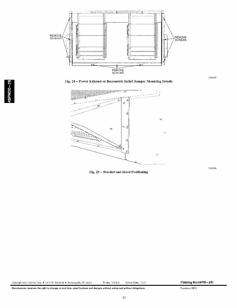
Step 12 -- Position Optional Power Exhaust or
Barometric Relief Damper Hood
The optional power exhaust or barometric relief dampers are
shipped assembled and tilted back into the unit for shipping.
Brackets and extra screws are shipped in shrink wrap around the
dampers.
1. Remove 9 screws holding each damper assembly in place.
(See Fig. 24.) Each damper assembly is secured with 3
screws on each side and 3 screws along the bottom. Save
screws.
PERSONAL INJURY HAZARD
Failure to follow this caution may result in personal iniury.
Be careful when tilting blower assembly. Hoods and
blowers are heavy and can cause iniury if dropped.
2. Pivot the damper assembly outward until top edge of the
damper assembly rests against the inside wall of unit.
3. Secure each damper assembly to unit with 6 screws across
top (3 screws provided) and bottom (3 screws from item 1)of damper.
4. With screws saved from item 1, install brackets on each side
of damper assembly. (See Fig. 25.)
5. Remove tape from damper blades.
Step 13 -- Non-Fused Disconnect
The handle for the factory-installed non-fused disconnect is
shipped inside the unit to prevent the handle from damage during
shipping. Follow these steps to complete installation of the handle,
ELECTRICAL SHOCK HAZARD
Failure to follow this warning could result in personaliniury or death,
Be sure power is shut-off to the unit from the buildingpower supply,
1. Open the control box access door.
2. Remove the small cover plate located on the unit corner
post near the control section.
3. Remove the inner control box cover. The handle and shaft
are located in a plastic bag at the bottom of the control box.
4. Insert the square shaft into the disconnect with the pins
vertical. On the 100-amp disconnect, the shaft is keyed into
the disconnect and can only be installed one way (with the
pins vertical).
5. Insert the handle through the corner post and onto the shaft
with the handle positioned so that "OFF" is on top.
6. Rotate the handle to the "ON" position to lock the pins intothe handle.
7. From the inside of the corner post, attach the handle
mounting screws to the handle. Slide the shaft fully into the
handle and tighten the set screw(s) on the disconnect to lock
the shaft. Tighten the screws that attach the handle to the
corner post.
8. Rotate the handle back to the "OFF" position.
9. Replace all panels and doors. Power can now be turnedback on to the unit.
Step 14 -- Install All Accessories
After all of the factory-installed options have been acliusted, install
all field-installed accessories. Refer to the accessory installation
instructions included with each accessory.
Step 15 -- Configure Controls
Refer to unit Controls and Troubleshooting book for information
on configuring controls.
H
19
HREMOVESCREWS
Fig. 24 - Power Exhaust or Barometric Relief Damper Mounting Details
Fig. 25 - Bracket and Hood Positioning
C06287
C06288
Copyright 2007 Carrier Corp, • 7310 W, Morris St. • Indianapolis, IN 46231 Printed in U,S,A, Edition Date: 11/07
Manufacturer reserves the right to change, at any time, specification8 and design8 without notice and without obligations,
Catalog No:48PM-2SI
Replaces: NEW
2O


![[] ELPH 37oZ - c.searspartsdirect.com · spray and excessive humidity. ... interference-causing equipment standard entiUed "Digital ... Main Sw_tch (-_ 19) Orange indicator (4 27)](https://img.pdfslide.us/doc/110x75/5b5de4eb7f8b9a415d8b6541/-elph-37oz-c-spray-and-excessive-humidity-interference-causing-equipment.jpg)