Embed Size (px)
Citation preview
INSTALLATION INSTRUCTIONS
SEP 100,000 to 400,000 Btuh Series
UNIT HEATERS IM-SEP-0652453-10 April 2018 Supersedes 65245309
Table Of Contents SEP Unit Dimensions . . . . . . . . . . . . . . . . . . . . . . . . . . . . 2 Shipping . . . . . . . . . . . . . . . . . . . . . . . . . . . . . . . . . . . . . . 3 Optional Accessories . . . . . . . . . . . . . . . . . . . . . . . . . . . . 3 CSA Requirements in USA . . . . . . . . . . . . . . . . . . . . . . . . 4 CSA Requirements in Canada . . . . . . . . . . . . . . . . . . . . . 4 Additional Requirements . . . . . . . . . . . . . . . . . . . . . . . . . 5 Unit Heater Installation . . . . . . . . . . . . . . . . . . . . . . . . . . . 5 Combustion and Ventilation Air . . . . . . . . . . . . . . . . . . 5 Rotation of Combustion Air Inducer . . . . . . . . . . . . . . . . . 5 Venting . . . . . . . . . . . . . . . . . . . . . . . . . . . . . . . . . . . . . . . 6 Electrical Connections . . . . . . . . . . . . . . . . . . . . . . . . . . . 11 Typical SEP Wiring Diagram . . . . . . . . . . . . . . . . . . . . . . 11 Gas Connection . . . . . . . . . . . . . . . . . . . . . . . . . . . . . . . . . 12 Leak Check . . . . . . . . . . . . . . . . . . . . . . . . . . . . . . . . . . . . . . 12
Unit Start−Up . . . . . . . . . . . . . . . . . . . . . . . . . . . . . . . . . . . . . . 12 To Turn Off Gas to Unit . . . . . . . . . . . . . . . . . . . . . . . . . . . . . . 14 Heating Sequence of Operation . . . . . . . . . . . . . . . . . . . . . . . . 14 Ignition Control LED . . . . . . . . . . . . . . . . . . . . . . . . . . . . . . . . . 14 High Altitude Adjustment . . . . . . . . . . . . . . . . . . . . . . . . . . . . . 14 Gas Flow . . . . . . . . . . . . . . . . . . . . . . . . . . . . . . . . . . . . . . . . . 16 Gas Pressure Adjustment . . . . . . . . . . . . . . . . . . . . . . . . . . . . 16 Limit Control Switch . . . . . . . . . . . . . . . . . . . . . . . . . . . . . . . . . 16 Louver Vane Adjustments . . . . . . . . . . . . . . . . . . . . . . . . . . . . 16 Combustion Air Pressure Switch . . . . . . . . . . . . . . . . . . . . . . . 16 Service . . . . . . . . . . . . . . . . . . . . . . . . . . . . . . . . . . . . . . . . . . . 16 Start−Up and Performance Checklist . . . . . . . . . . . . . . . . . . . . 17 Template . . . . . . . . . . . . . . . . . . . . . . . . . . . . . . . . . . . . . . . . . . 18 Warranty . . . . . . . . . . . . . . . . . . . . . . . . . . . . . . . . . . . . . . . . . . 19
RETAIN THESE INSTRUCTIONS
FOR FUTURE REFERENCE
WARNING
FIRE OR EXPLOSION HAZARD. Failure to follow safety warnings exactly could result in serious injury, death, or property damage.
Be sure to read and understand the installation, operation and service in-structions in this manual. Improper installation, adjustment, alter-ation, service or maintenance can cause serious injury, death or property damage. Do not store or use gasoline or other flammable vapors and liquids in the vi-cinity of this or any other appliance. Installation and service must be per-formed by a qualified installer, service agency or the gas supplier.
WHAT TO DO IF YOU SMELL GAS:
• Do not try to light any appliance. • Do not touch any electrical switch; do not use
any phone in your building. • Leave the building immediately. • Immediately call your gas supplier from a
neighbor’s phone. Follow the gas supplier’s in-structions.
• If you cannot reach your gas supplier, call the fire department.
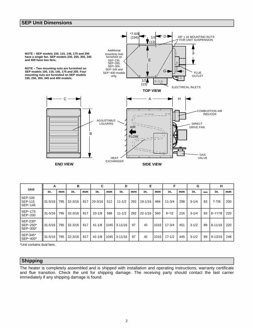
SEP Unit Dimensions NOTE – SEP models 100, 115, 145, 175 and 200 have a single fan. SEP models 230, 250, 300, 345 and 400 have two fans. NOTE – Two mounting nuts are furnished on SEP models 100, 115, 145, 175 and 200. Four mounting nuts are furnished on SEP models 230, 250, 300, 345 and 400 models.
*7-5/8
1/2
D
3/8" x 16 MOUNTING NUTS
(194)
FOR UNIT SUSPENSION
(13)
Additional
mounting nuts F
furnished on
SEP−230, E
SEP−250,
SEP−300,
SEP−345 and G
SEP−400 models FLUE
only. OUTLET
1/2
(13)
ELECTRICAL INLETS
C
B END VIEW
TOP VIEW
A H
COMBUSTION AIR INDUCER ADJUSTABLE
LOUVERS DIRECT AIR DRIVE FAN
FLOW
GAS HEAT VALVE
EXCHANGER SIDE VIEW
A B C D E F G H
Unit
in. mm in. mm in. mm in. mm in. mm in. mm in. mm in. mm
SEP-100
SEP-115 31-5/16 795 32-3/16 817 20-3/16 512 11-1/2 292 19-1/16 484 11-3/4 298 3-1/4 83 7-7/8 200
SEP−145
SEP−175 31-5/16 795 32-3/16 817 23-1/8 588 11-1/2 292 22-1/16 560 8−1/2 216 3-1/4 83 8−11/16 220
SEP−200
SEP-230*
SEP−250* 31-5/16 795 32-3/16 817 41-1/8 1045 3-11/16 97 40 1016 17-3/4 451 3-1/2 89 8-11/16 220
SEP−300*
SEP-345* 31-5/16 795 32-3/16 817 41-1/8 1045 3-11/16 97 40 1016 17-1/2 445 3-1/2 89 9-13/16 248
SEP−400*
*Unit contains dual fans. Shipping
The heater is completely assembled and is shipped with installation and operating instructions, warranty certificate and flue transition. Check the unit for shipping damage. The receiving party should contact the last carrier immediately if any shipping damage is found.
2

Optional Accessories TABLE 1
SEP−100 to SEP−230
Gas Part No. − Stainless Steel SEP−100S SEP−115S SEP−145S SEP−175S SEP−200S
Heating
Performance Part No. − Aluminized Steel SEP−100A SEP−115A SEP−145A SEP−175A SEP−200A
High Altitude
Pressure Switch 176722600 X 1 − − −
Kit
165296401 X
LPG/Propane Kit 165295202 X X X
165295205
X
1 Only SEP−175 requires replacement combustion air inducer pressure switch at altitudes over 2500 feet above sea level.
TABLE 2
SEP−230 to SEP−400
Gas Part No. − Stainless Steel SEP−230S SEP−250S SEP−300S SEP−345S SEP−400S
Heating
Performance Part No. − Aluminized Steel SEP−230A SEP−250A SEP−300A SEP−345A SEP−400A
Optional Accessories − Must Be Ordered Extra
Hanging Bracket 100001381 X X X X X
Kit
165296403 X X
LPG/Propane Kit 165295203 X X
165295206 X
3

CSA Requirements in USA
Installation of gas unit heaters must conform with local building codes or, in the absence of local codes, with the current edition of ANSI−Z223.1, National Fuel Gas Code. Installation in aircraft hangers must be in accordance with the current edition of ANSI/NFPA No. 409, Standard for Aircraft Hangers. Installation in parking structures must be in accordance with the current edition of ANSI/NFPA No. 88A, Standard for Parking Structures. Installation in repair garages must be in accordance with the current edition of ANSI/NFPA No. 88B, Standard for Repair Garages. Authorities having jurisdiction should be consulted before installation. Air for combustion and ventilation must conform to the methods outlined in the current edition of ANSI Z223.1, Section 5.3, Air for Combustion and Ventilation, or applicable provisions of local building codes. The National Fuel Gas Code (ANSI-Z223.1) is available from:
American National Standard Institute Inc. 11 West 42nd Street New York, NY 10036
These units are CSA international design−certified. These unit heaters are certified for clearances to combustible material as listed in table 1 and on unit rating plate. Accessibility and service clearances must be observed in addition to fire protection clearances. All electrical wiring and grounding for unit must be in accordance with the regulations of the current edition of ANSI/NFPA No. 70, National Electric Code. The National Electric Code is available from:
National Fire Protection Association 1 Batterymarch Park PO Box 9101 Quincy, MA 02269−9101
CSA Requirements in Canada These instructions are intended only as a general guide and do not supersede local codes in any way. Authorities having jurisdiction should be consulted before installation. The installation must conform with local building codes or, in the absence of local codes, with the current edition of CSA-B149 installation compliance codes. All electrical wiring and grounding for the unit must also comply with the current edition of CSA C22.1, Canadian Electrical Code.
These unit heaters are CSA-certified for clearances to combustible material listed on the rating plate and table 3. Adequate clearance must be provided around the appliance and around air openings into the combustion chamber. Provision must be made for service accessibility. NOTE: Fire protection clearances may be exceeded to provide additional space for service and accessibility.
TABLE 3 UNIT CLEARANCES TO COMBUSTIBLE MATERIALS
Top Sides Bottom Rear Flue
in mm in mm in mm in mm in mm
6 152 6 152 0 0 18 457 6 152
GARAGE / WAREHOUSE INSTALLATIONS
1 − In a storage area, clearance from the heater to combustible materials must be such that the combustible material must not attain a temperature above 160°F (71°C) during continuous operation of the unit.
WARNING
2 − Maintain an 8−foot (2.5 m) minimum clearance
from the floor to the bottom of the heater. Refer to the current edition of CSA-B149 installation compliance codes.
AIRCRAFT HANGER 1 − In an area where aircraft are housed or serviced, a
10−foot (3 m) minimum clearance from the highest surface of the aircraft to bottom of the heater must be maintained.
2 − In other areas, an 8-foot (2.5m) minimum clearance from the floor to bottom of heater must be maintained.
3 − Heaters should be located so that they are protected from damage from aircraft or other appliances needed for servicing of aircraft. Refer to requirements of the enforcing authorities.
In a confined area, the heater must be installed in accordance with the current edition of CSA-B149 installation compliance codes. Be sure to check with local codes and ordinances for additional requirements.
Combustible materials that are affected by exposure to temperatures less than 160°F (plastics, plastic wrap, styrofoam, cardboard, etc.) must be stored well away from this heater. Discharge air temperatures for these units can approach 200°F.
4
Additional Requirements
The Commonwealth of Massachusetts stipulates the following additional requirements:
1 − Gas furnaces shall be installed by a licensed plumber or gas fitter only.
2 − The gas cock must be T handle" type. Unit Heater Installation
WARNING
CAUTION
The appliance shall not be installed downstream from evaporator coils or cooling units. Install the unit in the desired location as governed by clearances, vent connection, air direction, gas supply, electrical supply and service accessibility.
On SEP models 100, 115, 145, 175, and 200, mounting nuts are furnished at the balance point (two positions only). On SEP models 230, 250, 300, 345 and 400, mounting nuts are furnished at each corner of the unit. Mounting nuts will accommodate 3/8" x 16 threaded rods.
1 − Cut threaded rods to desired length and slide a 3/8" nut onto the rod.
2 − Slide a flat washer onto the threaded rod AFTER the nut (7/16" inside diameter X 1" outside diameter X 1/16" thick washer).
3 − Screw the rods (two or four) into the mounting nuts on the unit.
4 − Tighten nuts to secure unit to rods.
TABLE 4 MAXIMUM MOUNTING HEIGHTS
Model Number Feet (Meters)
SEP−100 and SEP−115 16 (4.9)
SEP−145, SEP−175, and 20 (6.1)
SEP−200
SEP−230, SEP−250,
SEP−300, SEP−345 and 30 (9.1)
SEP−400
Combustion and Ventilation Air
Adequate facilities for supplying air for combustion and ventilation must be provided in accordance with the current edition of ANSI Z223.1, section 5.3, and CSA−B149 installation compliance codes, or applicable provisions of local building codes. All gas−fired appliances require air to be used for the combustion process. In many buildings today, there is a negative indoor air pressure caused by exhaust fans, etc. If sufficient quantities of combustion air are not available, the heater or another appliance will operate in an inefficient manner, resulting in incomplete combustion which can result in the production of excessive carbon monoxide.
CAUTION
If indoor air is to be used for combustion, it must be free of the following substances or the life of the heat exchanger will be adversely affected: chlorine, carbon tetrachloride, cleaning solvent, halogen refrigerants, acids, cements and glues, printing inks, fluorides, paint removers, varnishes, or any other corrosives. Rotation of Combustion Air Inducer (SEP−100, −115 and −145 Only)
The combustion air inducer on SEP models −100, −115 and −145 may be rotated 90° either to the left or right of the original vertical position in order to better suit the application. If the inducer is rotated, a new flue adapter is required (part #76708500). NOTE − It is not permissible to rotate the combustion air inducer on SEP models −175, −200, −230, −250, −300, −345 and −400. Rotate the combustion air inducer assembly as follows:
1 − Remove the heater from the carton. Decide the best unit heater orientation. The vent can be installed in one of three discharge positions: up, left, or right.
Improper installation, adjustment, alteration, ser-vice or maintenance can cause property damage, personal injury or loss of life. Installation and service must be performed by a licensed professional installer (or equivalent), service agency or the gas supplier.
As with any mechanical equipment, personal injury can result from contact with sharp sheet metal edges. Be careful when you handle this equipment.
Insufficient combustion air can cause headaches, nausea, dizziness, asphyxiation or death.
5
2 − If the inducer is to be rotated, follow the
instructions in this section; otherwise, refer to instructions under Venting" section.
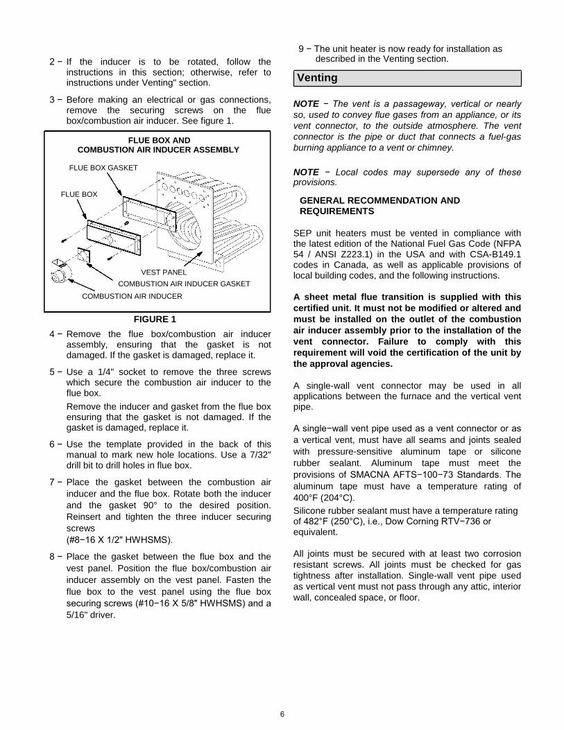
3 − Before making an electrical or gas connections, remove the securing screws on the flue box/combustion air inducer. See figure 1.
FLUE BOX AND
COMBUSTION AIR INDUCER ASSEMBLY
FLUE BOX GASKET FLUE BOX
VEST PANEL COMBUSTION AIR INDUCER GASKET
COMBUSTION AIR INDUCER
FIGURE 1 4 − Remove the flue box/combustion air inducer
assembly, ensuring that the gasket is not damaged. If the gasket is damaged, replace it.
5 − Use a 1/4" socket to remove the three screws
which secure the combustion air inducer to the flue box. Remove the inducer and gasket from the flue box ensuring that the gasket is not damaged. If the gasket is damaged, replace it.
6 − Use the template provided in the back of this
manual to mark new hole locations. Use a 7/32" drill bit to drill holes in flue box.
7 − Place the gasket between the combustion air
inducer and the flue box. Rotate both the inducer and the gasket 90° to the desired position. Reinsert and tighten the three inducer securing screws (#8−16 X 1/2" HWHSMS).
8 − Place the gasket between the flue box and the
vest panel. Position the flue box/combustion air inducer assembly on the vest panel. Fasten the flue box to the vest panel using the flue box securing screws (#10−16 X 5/8" HWHSMS) and a 5/16" driver.
9 − The unit heater is now ready for installation as described in the Venting section.
Venting
NOTE − The vent is a passageway, vertical or nearly so, used to convey flue gases from an appliance, or its vent connector, to the outside atmosphere. The vent connector is the pipe or duct that connects a fuel-gas burning appliance to a vent or chimney. NOTE − Local codes may supersede any of these provisions.
GENERAL RECOMMENDATION AND REQUIREMENTS
SEP unit heaters must be vented in compliance with the latest edition of the National Fuel Gas Code (NFPA 54 / ANSI Z223.1) in the USA and with CSA-B149.1 codes in Canada, as well as applicable provisions of local building codes, and the following instructions. A sheet metal flue transition is supplied with this certified unit. It must not be modified or altered and must be installed on the outlet of the combustion air inducer assembly prior to the installation of the vent connector. Failure to comply with this requirement will void the certification of the unit by the approval agencies. A single-wall vent connector may be used in all applications between the furnace and the vertical vent pipe. A single−wall vent pipe used as a vent connector or as a vertical vent, must have all seams and joints sealed with pressure-sensitive aluminum tape or silicone rubber sealant. Aluminum tape must meet the provisions of SMACNA AFTS−100−73 Standards. The aluminum tape must have a temperature rating of 400°F (204°C). Silicone rubber sealant must have a temperature rating of 482°F (250°C), i.e., Dow Corning RTV−736 or equivalent. All joints must be secured with at least two corrosion resistant screws. All joints must be checked for gas tightness after installation. Single-wall vent pipe used as vertical vent must not pass through any attic, interior wall, concealed space, or floor.
6
VERTICAL VENTS USING METAL VENT PIPE All SEP unit heaters are listed as Category 1 appliances for vertical vent installations.
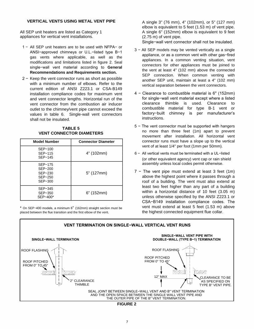
1 − All SEP unit heaters are to be used with NFPA− or ANSI−approved chimneys or U.L.−listed type B−1 gas vents where applicable, as well as the modifications and limitations listed in figure 2. Seal single−wall vent material according to General Recommendations and Requirements section.
2 − Keep the vent connector runs as short as possible with a minimum number of elbows. Refer to the current edition of ANSI Z223.1 or CSA-B149 installation compliance codes for maximum vent and vent connector lengths. Horizontal run of the vent connector from the combustion air inducer outlet to the chimney/vent pipe cannot exceed the values in table 6. Single-wall vent connectors shall not be insulated.
TABLE 5
VENT CONNECTOR DIAMETERS
Model Number Connector Diameter
SEP−100 SEP−115 4" (102mm) SEP−145
SEP−175 SEP−200 SEP−230 5" (127mm) SEP−250 SEP−300
SEP−345 SEP−350 6" (152mm) SEP−400*
* On SEP−400 models, a minimum 6" (162mm) straight section must be placed between the flue transition and the first elbow of the vent.
A single 3" (76 mm), 4" (102mm), or 5" (127 mm) elbow is equivalent to 5 feet (1.53 m) of vent pipe. A single 6" (152mm) elbow is equivalent to 9 feet (2.75 m) of vent pipe. Single−wall vent connector shall not be insulated.
3 − All SEP models may be vented vertically as a single
appliance, or as a common vent with other gas−fired appliances. In a common venting situation, vent connectors for other appliances must be joined to the vent at least 4" (102 mm) above the connected SEP connection. When common venting with another SEP unit, maintain at least a 4" (102 mm) vertical separation between the vent connectors.
4 − Clearance to combustible material is 6" (152mm)
for single−wall vent material except where a listed clearance thimble is used. Clearance to combustible material for type B-1 vent or factory−built chimney is per manufacturer’s instructions.
5 − The vent connector must be supported with hangers
no more than three feet (1m) apart to prevent movement after installation. All horizontal vent connector runs must have a slope up to the vertical vent of at least 1/4" per foot (1mm per 50mm).
6 − All vertical vents must be terminated with a UL−listed (or other equivalent agency) vent cap or rain shield assembly unless local codes permit otherwise.
7 − The vent pipe must extend at least 3 feet (1m)
above the highest point where it passes through a roof of a building. The vent must also extend at least two feet higher than any part of a building within a horizontal distance of 10 feet (3.05 m) unless otherwise specified by the ANSI Z223.1 or CSA−B149 installation compliance codes. The vent must extend at least 5 feet (1.53 m) above the highest connected equipment flue collar.
VENT TERMINATION ON SINGLE−WALL VERTICAL VENT RUNS SINGLE−WALL VENT PIPE WITH
SINGLE−WALL TERMINATION DOUBLE−WALL (TYPE B−1) TERMINATION ROOF FLASHING ROOF PITCHED FROM 0" TO 45"
2" CLEARANCE
THIMBLE
ROOF FLASHING
ROOF PITCHED
FROM 0" TO 45"
12" MAX CLEARANCE TO BE
AS SPECIFIED ON
TYPE B" VENT PIPE.
SEAL JOINT BETWEEN SINGLE−WALL VENT AND B" VENT TERMINATION AND THE OPEN SPACE BETWEEN THE SINGLE WALL VENT PIPE AND
THE OUTER PIPE OF THE B" VENT TERMINATION. FIGURE 2 7

TABLE 6 MAXIMUM HORIZONTAL VENT CONNECTOR AND
HORIZONTAL VENT PIPE LENGTHS SEP−100, −115, SEP−230,
No. of −145, −175, and −250 and SEP−345 SEP−400
−200 −300
Elbows
ft m ft m ft m ft m
1 25 7.6 35 10.7 31 9.4 21 6.4
2 20 6.1 30 9.1 22 6.7 12 3.6
3 15 4.6 25 7.6 13 4.0 3 0.9
4 10 3.0 20 6.1 4 1.2 −− −−
5 5 1.5 15 4.6 −− −− −− −−
6 −− −− 10 3.0 −− −− −− −−
7 −− −− 5 1.5 −− −− −− −−
HORIZONTAL VENTING
NOTE − Common venting is not allowed when horizontally venting the unit heater. If the SEP unit heater is to be horizontally vented, a positive pressure may be created in the vent. The unit heater, when installed with horizontal venting, will perform as a category III appliance. 1 − Special vent materials approved for use with
Category III appliances may be used with these units. Refer to table 7 for venting components.
2 − If possible, do not terminate the horizontal vent
through a wall that is exposed to prevailing wind. Exposure to excessive winds can affect unit performance. If such a termination is necessary, use a wind block to protect the vent termination from direct winds.
3 − Vent termination must be free from obstructions and at least 12" (30.5 cm) above grade level and maximum snow height.
4 − Do not terminate vent directly below roof eaves or above a public walkway, or any other area where condensate dripping may be troublesome and may cause some staining. Avoid windows where steam may cause fogging or ice buildup.
5 − Minimum clearance for horizontal vent termination from any door, window, gravity air inlet, gas or electric meter, regulators, and relief equipment is 4 feet (1m) for United States installations. In Canada, horizontal vent termination must have a minimum 6−foot horizontal clearance from gas and electric meters and relief devices.
Refer to latest editions of the ANSI Z223.1 or CSA−B149 for installation compliance codes and with local authorities with jurisdiction.
6 − Vent termination must be a minimum of 4 feet (1.2m) horizontally from any soffit or under-eave vent.
7 − Vent termination must be a minimum of 6 feet (1.83 m) from an inside corner formed by two exterior walls. If possible, leave a 10−foot clearance.
8 − Vent termination must be a minimum of 10 feet (3m) from any forced air inlet (includes fresh air inlet for other appliances, such as a dryer).
9 − For upward sloped vent, a condensate tee and drain must be installed within the first 5 feet (2m) from the unit heater to protect the appliance. If the unit is shut down for an extended period of time and will be exposed to sub-freezing temperatures, the condensate may freeze.
10 − For upward sloped vent, see figure 3, condensate
tee and drain must be installed within the first 5 feet (1.53 m) from the unit heater to protect the appliance.
11 − Flexible loop trap in condensate line (if used) must be filled with water to prevent combustion products from entering structure.
12 − Select a wall termination point that will maintain
1/4" rise per foot slope of horizontal run of vent pipe. In areas where authorities having jurisdiction permit, a downward slope of maximum 1/4" per foot is also acceptable. Condensate drainage can be collected in a tee pipe section (figure 4) with drain loop similar to one used for upward slope vent, or allowed to drip through the vent termination, if permitted by authorities (figure 5).
13 For horizontal venting, the vent pipe must be supported with hangers no more than 3 feet (1m) apart to prevent movement after installation.
14 − All horizontal vent applications which use Category III vent pipe must terminate with an approved Category III tee. Opening end must face downward.
15 − When termination is routed through an exterior combustible wall, the vent must be supported using a listed clearance thimble. Inside edge of vent termination tee or elbow must be at least 12" (305mm) from outside wall.
8
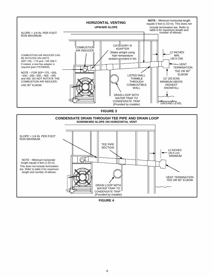
SLOPE = 1/4 IN. PER FOOT RUN MAXIMUM. COMBUSTION AIR INDUCER CAN BE ROTATED ON UNITS SEP−100, −115 and −145 ONLY. If rotated, a new flue adapter is required (part #76708500). NOTE − FOR SEP−175, −200, −230, −250 −250, −300, −345 and 400. DO NOT ROTATE THE COMBUSTION AIR INDUCER; USE 90° ELBOW.
HORIZONTAL VENTING NOTE − Minimum horizontal length
equals 5 feet (1.53 m). This does not
UPWARD SLOPE include termination tee. Refer to
table 6 for maximum length and
number of elbows.
COMBUSTION CATEGORY III
ADAPTER
AIR INDUCER
(Make airtight using 12 INCHES
high−temperature MIN.
sealant provided in kit) (30.5 CM)
VENT
TERMINATION
TEE OR 90°
LISTED WALL ELBOW
THIMBLE 12" (30.5CM)
THROUGH MINIMUM ABOVE
COMBUSTIBLE HIGHEST
WALL SNOWFALL
DRAIN LOOP WITH
WATER TRAP TO
CONDENSATE TRAP GROUND LEVEL
(Provided by installer)
FIGURE 3
CONDENSATE DRAIN THROUGH TEE PIPE AND DRAIN LOOP
DOWNWARD SLOPE ON HORIZONTAL VENT SLOPE = 1/4 IN. PER FOOT RUN MAXIMUM.
NOTE − Minimum horizontal length equals 5 feet (1.53 m).
This does not include termination tee. Refer to table 6 for maximum
length and number of elbows.
TEE PIPE SECTION
DRAIN LOOP WITH WATER TRAP TO
CONDENSATE TRAP (Provided by installer)
12 INCHES (30.5 cm) MINIMUM
VENT TERMINATION TEE OR 90° ELBOW
FIGURE 4
9
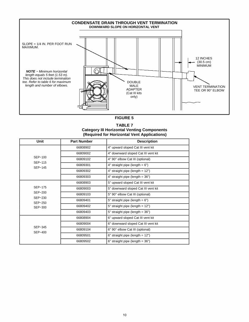
CONDENSATE DRAIN THROUGH VENT TERMINATION DOWNWARD SLOPE ON HORIZONTAL VENT
SLOPE = 1/4 IN. PER FOOT RUN MAXIMUM.
NOTE − Minimum horizontal length equals 5 feet (1.53 m).
This does not include termination tee. Refer to table 6 for maximum
length and number of elbows.
12 INCHES
(30.5 cm)
MINIMUM
DOUBLE
MALE VENT TERMINATION
ADAPTER
TEE OR 90° ELBOW
(Cat III kits
only)
FIGURE 5 TABLE 7
Category III Horizontal Venting Components (Required for Horizontal Vent Applications)
Unit Part Number Description
66808902 4" upward sloped Cat III vent kit
66809002 4" downward sloped Cat III vent kit
SEP−100
66809102 4" 90° elbow Cat III (optional)
SEP−115
66809301 4" straight pipe (length = 6")
SEP−145
66809302 4" straight pipe (length = 12")
66809303 4" straight pipe (length = 36")
66808903 5" upward sloped Cat III vent kit
SEP−175
66809003 5" downward sloped Cat III vent kit
SEP−200
66809103 5" 90° elbow Cat III (optional)
SEP−230
66809401 5" straight pipe (length = 6")
SEP−250
66809402 5" straight pipe (length = 12")
SEP−300
66809403 5" straight pipe (length = 36")
66808904 6" upward sloped Cat III vent kit
66809004 6" downward sloped Cat III vent kit
SEP−345
66809104 6" 90° elbow Cat III (optional)
SEP−400
66809501 6" straight pipe (length = 12")
66809502 6" straight pipe (length = 36")
10

Electrical Connections
NOTE − Local codes may supersede any of the provisions outlined in this instruction. The SEP series unit heaters use a direct spark ignition system. There is no pilot necessary as the spark lights the main burner as the gas valve is turned on. The direct spark ignition control board emits radio noise as the sparking process is under way. The level of energy may be sufficient to disturb a logic circuit in a microprocessor controlled thermostat. It is recommended that an isolation relay be used when connecting the SEP series unit heaters to a microprocessor−controlled thermostat. Install the thermostat according to instructions provided by the manufacturer. Install a separate fused disconnect switch, with the fuse sized according to blower motor size.
Connect wiring through knockout on the junction box located on the side of the unit heater. Refer to heater wiring diagram for connection information. Use 18 gauge wire or larger for thermostat connections. NOTE − Electrically ground unit in accordance with local codes or, in the absence of local codes, in accordance with the current National Electrical Code (ANSI/NFPA No. 70) in the U.S.A., and in Canada with the current Canadian Electrical Code, Part 1 (CSA C22.1). NOTE − Uninsulated ground wires must be wrapped in electrical tape to avoid damage to the electrical system. Connect field wiring as shown on wiring diagram on unit. Also refer to typical diagram in this manual. An additional thermostat wire must be run to terminal G" on heater when continuous blower is desired.
TYPICAL SEP WIRING SCHEMATIC
11

Gas Connection
When connecting gas supply, the length of the run from the meter must be considered in determining the pipe size to avoid excessive pressure drop. A line pressure of 7" w.c. (178 mm w.c.) for natural gas should be maintained when sizing piping. For correct sizing of piping, consult the utility having jurisdiction. A drip leg should be installed in the vertical pipe run to the unit. In some localities, codes may require that a manual main shutoff valve and union (furnished by installer) be installed external to the unit. Union must be of the ground joint type. See figure 6. A 1/8" NPT plugged tap must be installed immediately upstream of the gas supply connection to the heater. NOTE − Compounds used on threaded joints of gas piping must be resistant to the actions of liquefied petroleum gases.
GAS SUPPLY CONNECTION
MANUAL
MAIN SHUT−OFF VALVE
(Furnished by Installer)
GROUND
JOINT UNION
1/8 NPT
PLUGGED GAS FLOW
TAP
DRIP LEG
FIGURE 6 Leak Check
After gas piping is completed, carefully check all piping connections, (field and factory), for gas leaks. Use a soap solution or other preferred means.
CAUTION
The appliance must be isolated from the gas supply piping system by closing its individual manual gas shutoff valve during any pressure testing of the gas supply system at test pressures equal to or less than 1/2 psig (3.45kPa).
IMPORTANT
NOTE − In case emergency shutdown is required, shut down main gas valve and disconnect main power to unit. These devices should be properly labeled by the installer.
GAS SUPPLY TO UNIT HEATER MANUAL MAIN SHUT−OFF
DISCONNECT GAS
VALVE WILL NOT HOLD
NORMAL TEST VALVE WHEN TEST
PRESSURES OF 1/2 psig PRESSURES OF
1/2 psig (3.45kPa)
(3.45kPa) OR HIGHER
OR HIGHER WILL
BE USED.
CAP
UNIT HEATER
FIGURE 7
Unit Start−Up
FOR YOUR SAFETY READ BEFORE LIGHTING
WARNING
Electric shock hazard. Can cause injury or death. Do not use this appliance if any part has been under water. Immedi-ately call a qualified service technician to inspect the furnace and to replace any part of the control system and any gas control which has been under wa-ter.
WARNING
Danger of explosion. Can cause injury or product or property damage. If overheating occurs or if gas supply fails to shut off, shut off the manual gas valve to the appliance before shutting off electrical supply.
The heater and its individual shut off valve must be disconnected from the gas supply piping system during any pressure testing of that system at test pressures in excess of 1/2 psig (3.45kPa). See figure 7.
DO NOT use matches, candles, flame or other sources of ignition to check for gas leaks.
Electric shock hazard. Can cause injury or death. Do not use this appliance if any part has been under water. Immediately call a qualified service technician to inspect the furnace and to replace any part of the control system and any gas control which has been under water.
Danger of explosion. Can cause injury or product or property damage. If overheating occurs or if gas supply fails to shut off, shut off the manual gas valve to the appliance before shutting off electrical supply.
12
WARNING
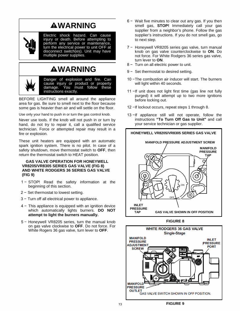
Electric shock hazard. Can cause injury or death. Before attempting to perform any service or maintenance, turn the electrical power to unit OFF at disconnect switch(es). Unit may have multiple power supplies.
WARNING
Danger of explosion and fire. Can cause injury or product or property damage. You must follow these instructions exactly.
BEFORE LIGHTING smell all around the appliance area for gas. Be sure to smell next to the floor because some gas is heavier than air and will settle on the floor. Use only your hand to push in or turn the gas control knob. Never use tools. If the knob will not push in or turn by hand, do not try to repair it, call a qualified service technician. Force or attempted repair may result in a fire or explosion. These unit heaters are equipped with an automatic spark ignition system. There is no pilot. In case of a safety shutdown, move thermostat switch to OFF, then return the thermostat switch to HEAT position.
GAS VALVE OPERATION FOR HONEYWELL VR8205/VR8305 SERIES GAS VALVE (FIG 8) AND WHITE RODGERS 36 SERIES GAS VALVE (FIG 9)
1 − STOP! Read the safety information at the
beginning of this section. 2 − Set thermostat to lowest setting. 3 − Turn off all electrical power to appliance. 4 − This appliance is equipped with an ignition device
which automatically lights burners. DO NOT attempt to light the burners manually.
5 − Honeywell VR8205 series, turn the manual knob
on gas valve clockwise to OFF. Do not force. For White Rogers 36 gas valve, turn lever to OFF.
6 − Wait five minutes to clear out any gas. If you then smell gas, STOP! Immediately call your gas supplier from a neighbor’s phone. Follow the gas supplier’s instructions. If you do not smell gas, go to next step.
7 − Honeywell VR8205 series gas valve, turn manual
knob on gas valve counterclockwise to ON. Do not force. For White Rodgers 36 series gas valve, turn lever to ON.
8 − Turn on all electric power to unit. 9 − Set thermostat to desired setting. 10 − The combustion air inducer will start. The burners
will light within 40 seconds. 11 − If unit does not light first time (gas line not fully
purged) it will attempt up to two more ignitions before locking out.
12 − If lockout occurs, repeat steps 1 through 8. 13 − If appliance still will not operate, follow the
instructions “To Turn Off Gas to Unit" and call your service technician or gas supplier.
HONEYWELL VR8205/VR8305 SERIES GAS VALVE
MANIFOLD PRESSURE ADJUSTMENT SCREW
MANIFOLD PRESSURE
TAP
ON
OFF
INLET PRESSURE TAP GAS VALVE SHOWN IN OFF POSITION
Electric shock hazard. Can cause injury or death. Before attempting to perform any service or maintenance, turn the electrical power to unit OFF at disconnect switch(es). Unit may have multiple power supplies.
Danger of explosion and fire. Can cause injury or product or property damage. You must follow these instructions exactly.
FIGURE 9
FIGURE 8
13
To Turn Off Gas to Unit 1 − Set thermostat to lowest level. 2 − Turn off all electrical power to unit if service is to
be performed. 3 − Honeywell VR8205 series gas valve, turn knob 90
degrees clockwise to OFF. Do not force. For White Rodgers 36 series gas valve, move lever to OFF.
Heating Sequence of Operation
1 − When the thermostat calls for heat, the combustion air inducer starts immediately.
2 − Combustion air pressure switch proves inducer operation before allowing power to the ignition controller. This switch is factory-set and no adjustment is necessary.
3 − After prepurge of approximately 30 seconds, the spark ignition is energized and the solenoid valves open in the gas valve. SEP models 230, 250, 300, 345 and 400 are equipped with a step opening valve. During ignition phase of start-up, a pressure of approximately 25% of full rate allows even ignition of all burners for several seconds before full rate pressure is established.
4 − The spark then ignites the gas, the ignition sensor proves the flame, and the combustion process continues.
5 − in the event that the flame is not detected after the first 10−second trial for ignition, the controller will repeat steps 3 and 4 an additional two times before locking out the gas valve. Ignition control will then automatically repeat steps 3, 4, and 5 after 60 minutes.
NOTE: To interrupt the 60−minute lockout period, move thermostat from Heat" to OFF" then back to Heat." Heating sequence then restarts at step 1.
6 − The burners must light without noticeable crossover delay. There must be no flame lifting from the burner heads, flashback or burning within the burner. The flames should be predominantly blue in color and should be approximately centered in the tubes with no apparent impingement taking place.
7 − The ignition control will energize the fan(s)
approximately 45 seconds after ignition is established.
8 − After the thermostat demand is satisfied, the gas valve is closed. Five seconds after the demand is satisfied, the combustion air inducer is shut off.
9 − The ignition control must shut off the system fan approximately 150 seconds after the gas valve is de-energized.
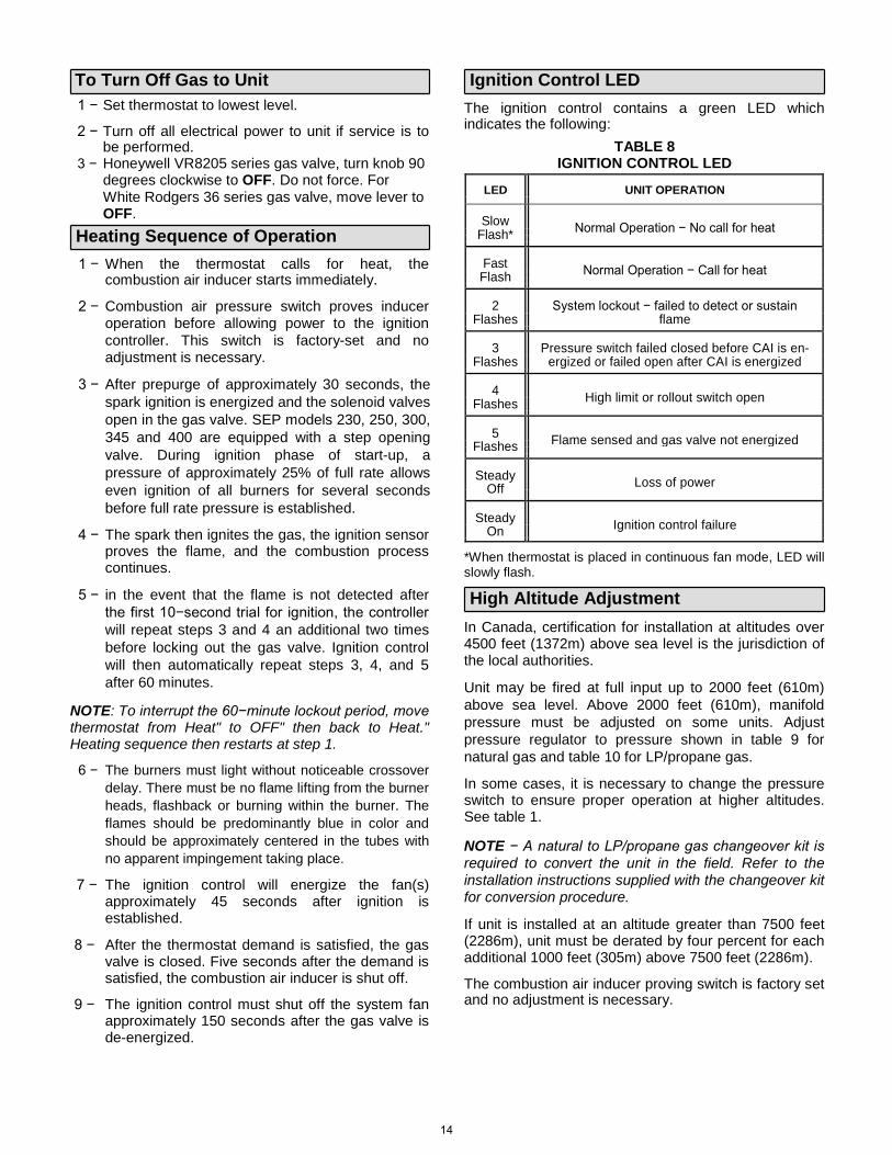
Ignition Control LED The ignition control contains a green LED which indicates the following:
TABLE 8 IGNITION CONTROL LED
LED UNIT OPERATION
Slow Normal Operation − No call for heat
Flash*
Fast Normal Operation − Call for heat
Flash
2 System lockout − failed to detect or sustain
Flashes flame
3 Pressure switch failed closed before CAI is en-
Flashes ergized or failed open after CAI is energized
4 High limit or rollout switch open
Flashes
5 Flame sensed and gas valve not energized
Flashes
Steady Loss of power
Off
Steady Ignition control failure
On
*When thermostat is placed in continuous fan mode, LED will slowly flash. High Altitude Adjustment
In Canada, certification for installation at altitudes over 4500 feet (1372m) above sea level is the jurisdiction of the local authorities. Unit may be fired at full input up to 2000 feet (610m) above sea level. Above 2000 feet (610m), manifold pressure must be adjusted on some units. Adjust pressure regulator to pressure shown in table 9 for natural gas and table 10 for LP/propane gas. In some cases, it is necessary to change the pressure switch to ensure proper operation at higher altitudes. See table 1. NOTE − A natural to LP/propane gas changeover kit is required to convert the unit in the field. Refer to the installation instructions supplied with the changeover kit for conversion procedure. If unit is installed at an altitude greater than 7500 feet (2286m), unit must be derated by four percent for each additional 1000 feet (305m) above 7500 feet (2286m). The combustion air inducer proving switch is factory set and no adjustment is necessary.
14
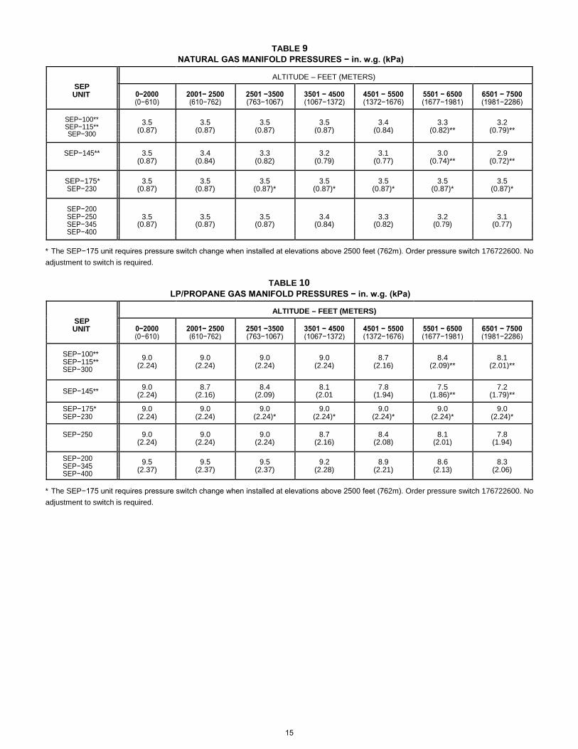
TABLE 9 NATURAL GAS MANIFOLD PRESSURES − in. w.g. (kPa)
ALTITUDE – FEET (METERS)
SEP
0−2000 2001− 2500 2501 −3500 3501 − 4500 4501 − 5500 5501 − 6500 6501 − 7500
UNIT
(0−610) (610−762) (763−1067) (1067−1372) (1372−1676) (1677−1981) (1981−2286)
SEP−100** 3.5 3.5 3.5 3.5 3.4 3.3 3.2
SEP−115**
(0.87) (0.87) (0.87) (0.87) (0.84) (0.82)** (0.79)**
SEP−300
SEP−145** 3.5 3.4 3.3 3.2 3.1 3.0 2.9
(0.87) (0.84) (0.82) (0.79) (0.77) (0.74)** (0.72)**
SEP−175* 3.5 3.5 3.5 3.5 3.5 3.5 3.5
SEP−230 (0.87) (0.87) (0.87)* (0.87)* (0.87)* (0.87)* (0.87)*
SEP−200
SEP−250 3.5 3.5 3.5 3.4 3.3 3.2 3.1
SEP−345 (0.87) (0.87) (0.87) (0.84) (0.82) (0.79) (0.77)
SEP−400
* The SEP−175 unit requires pressure switch change when installed at elevations above 2500 feet (762m). Order pressure switch 176722600. No adjustment to switch is required.
TABLE 10 LP/PROPANE GAS MANIFOLD PRESSURES − in. w.g. (kPa)
ALTITUDE – FEET (METERS)
SEP
0−2000 2001− 2500 2501 −3500 3501 − 4500 4501 − 5500 5501 − 6500 6501 − 7500
UNIT
(0−610) (610−762) (763−1067) (1067−1372) (1372−1676) (1677−1981) (1981−2286)
SEP−100** 9.0 9.0 9.0 9.0 8.7 8.4 8.1
SEP−115**
(2.24) (2.24) (2.24) (2.24) (2.16) (2.09)** (2.01)**
SEP−300
SEP−145** 9.0 8.7 8.4 8.1 7.8 7.5 7.2
(2.24) (2.16) (2.09) (2.01 (1.94) (1.86)** (1.79)**
SEP−175* 9.0 9.0 9.0 9.0 9.0 9.0 9.0
SEP−230 (2.24) (2.24) (2.24)* (2.24)* (2.24)* (2.24)* (2.24)*
SEP−250 9.0 9.0 9.0 8.7 8.4 8.1 7.8
(2.24) (2.24) (2.24) (2.16) (2.08) (2.01) (1.94)
SEP−200 9.5 9.5 9.5 9.2 8.9 8.6 8.3
SEP−345
(2.37) (2.37) (2.37) (2.28) (2.21) (2.13) (2.06)
SEP−400
* The SEP−175 unit requires pressure switch change when installed at elevations above 2500 feet (762m). Order pressure switch 176722600. No adjustment to switch is required.
15
Gas Flow To check for proper gas flow to the combustion chamber, determine the Btu input from the appliance rating plate. Divide this input rating by the Btu per cubic feet of available gas. Result is the required number of cubic feet per hour. Determine the flow of gas through the gas meter for two minutes and multiply by 30 to get the hourly flow of gas. Gas Pressure Adjustment
1 − Check gas line pressure with unit firing at maximum
rate. A minimum of 5" (127mm) w.c. for natural gas or 11" (279mm) w.c. for LP/propane gas should be maintained for proper unit operation.
2 − After line pressure has been checked and adjusted,
check regulator pressure. Adjust manifold pressure to values specified on the unit rating plate. See figures 8, 9, and 10 for gas pressure adjustment screw location. A natural gas to LP/propane gas changeover kit is required to convert unit in the field. Refer to installation instructions provided with changeover kit for conversion procedure.
Limit Control Switch
The limit control switch(es) are factory-set and are not field-adjustable. Louver Vane Adjustment
The SEP series unit heaters are provided with adjustable louver vanes. Air flow from the unit can be directed down, straight, out, up, or any combination of these.
WARNING
DO NOT CLOSE the bottom three lou-vers on SEP. Premature failure to the heat exchanger can occur.
Combustion Air Pressure Switch
This pressure switch checks for proper combustion air inducer operation before allowing an ignition trial. The switch is factory−set and no field adjustment is necessary.
Service
CAUTION
The unit heater and vent system shall be inspected once a year by a licensed professional service technician, or equivalent.
LUBRICATION
1 − Combustion air inducer motor bearings are pre−lubricated and sealed. No further lubrication is necessary.
2 − Fan motor bearings should be lubricated according to manufacturer’s instructions on each motor. If no instruction is provided, use the following as a guide: motors with oiling ports are pre−lubricated for an extended bearing life, re−lubricate with a few drops of SAE No. 10 non−detergent oil once every two years.
BURNERS
1 − Periodically examine burner flames for proper appearance during the heating season.
2 − Before each heating season examine the burners for any deposits or blockage that may have occurred.
3 − Clean burners as follows: a − Turn off both electrical and gas supplies to unit. b − Disconnect gas supply piping, high tension
and sensor leads. Remove gas manifold. Remove burner tray.
c − Clean burners as necessary. Make sure that burner heads line up properly to ensure flame crossover. Check spark gap on electrode and adjust if required. The gap should be between 0.110" and 0.140" (2.8 mm to 3.6 mm). The gap may be checked with appropriately sized twist drills or feeler gauges.
d − Reinstall burner tray, gas manifold, high tension and sensor leads. Reconnect gas supply piping.
e − Restore electrical power and gas supply. Follow lighting instructions to light unit. Check burner flame.
Turn off gas and electrical power to unit before per-forming any maintenance or service operations on this unit. Remember to follow lighting instructions when putting unit back into operation after service or maintenance.
DO NOT CLOSE the bottom three louvers on SEP. Premature failure to the heat exchanger can occur.
16
FLUE PASSAGEWAY AND FLUE BOX The flue passages and flue box should be inspected and cleaned prior to each heating season. The sequence of operation should be as follows: 1 − Turn off both electrical and gas supply to unit. 2 − Disconnect combustion air inducer wiring. 3 − Remove screws securing flue box to unit. Remove
flue box. If necessary, remove blower assembly from flue box. Clean flue box with wire brush.
4 − Remove baffle retention bracket and flue baffles. Clean flue baffles with wire brush.
5 − Remove burners as described in Burners" section. 6 − Clean tubes with a wire brush. 7 − Reassemble unit. The combustion air and flue box
gaskets should also be replaced during reassembly.
8 − Restore electrical power and gas supply. Follow
lighting instructions to light unit. Check operation of unit.
COMBUSTION AIR INDUCER Under normal operating conditions, the combustion air inducer should be checked and cleaned prior to the heating season with the power supply disconnected. Use a small brush to clean inducer wheel.
ELECTRICAL 1 − Check all wiring for loose connections. 2 − Check for correct voltage at unit (unit operating). 3 − Check amperage draw.
FLUE AND CHIMNEY Check all vent and vent connector joints for tightness. Ensure that connections are sealed and that there are no blockages.
FAILURE TO OPERATE If unit fails to operate check the following:
1 − Is thermostat calling for heat? 2 − Is main disconnect closed? 3 − Is there a breaker tripped or a fuse blown? 4 − Is gas turned on at meter? 5 − Is manual shutoff valve open? 6 − Is unit ignition system in lock out? If unit locks out
again, call service technician to inspect unit. 7 − Is pressure switch closed? Obstructed flue will
cause unit to shut off at pressure switch. Check flue passage and outlet.
SAFETY SHUT−OFF VALVE TEST The safety shut−off valve test procedure is as follows:
1 − Turn off the manual gas valve. 2 − Set the thermostat to call for heat. 3 − System begins normal sequence of operation. 4 − After approximately 30 seconds (pre purge period)
the LED will fast flash indicating the gas valve is powered.
5 − After 10 seconds, the gas valve closes and steps
4 and 5 will repeat two additional times before locking out the gas valve, which will be indicated by two flashes on the LED.
6 − To restart the system, de−energize the thermostat
call for heat and follow the operating instructions under Unit Start−Up".
REPAIR PARTS When ordering repair parts include the complete unit model number listed on the unit rating plate. For example: SEP−175A−1.
START−UP AND PERFORMANCE CHECKLIST
Job Name: Job No.: Date:
Job Location: City: State/Province:
Installer: City: State/Province:
Unit Model No.: Serial No.: Service Technician:
Electrical Connections Tight? Air Shutters Properly Adjusted (If Installed)?
Supply Voltage
Flue Connections Tight?
Blower Motor Lubrication O.K.?
Fan Timer Operation Checked?
Gas Piping Connections Tight & Leak−Tested?
THERMOSTAT
Blower Motor Amps
Furnace Btu Input Calibrated?
Heat Anticipator Properly Set?
Line Pressure
Manifold Pressure w.c. Level?
17
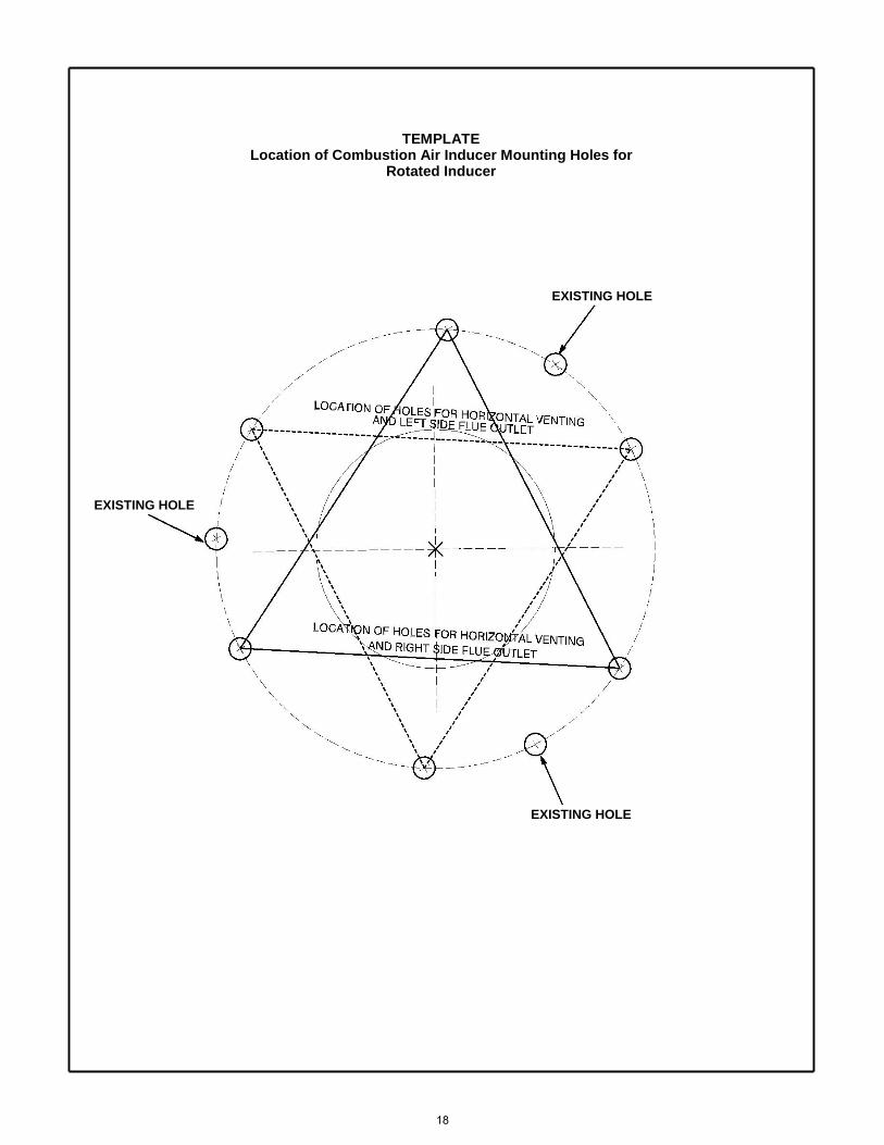
TEMPLATE Location of Combustion Air Inducer Mounting Holes for
Rotated Inducer
EXISTING HOLE EXISTING HOLE
EXISTING HOLE 18
ADP Unit Heater Limited Warranty
Term of Warranty: Advanced Distributor Products (ADP) warrants that products sold shall be of merchantable quality, free of defects in material and workmanship, under normal use and service, for a period of five (2) years from the date of installation, not to exceed six (3) years from the date of manufacture subject to the terms of ADP’s limited warranty.
Unit Heater Extended Components: This warranty provides extended coverage on Aluminized Heat Exchangers for ten (10) years and Stainless Steel Heat Exchangers for fifteen (15) years. The extended warranty coverage begins with the installation date and represents the total warranty period for the specific component. ADP, at its option, will furnish a replacement heat exchanger or allow a credit (in the amount of the heat exchanger original selling price) toward the purchase of a new ADP unit heater. No extended coverage granted for HED series heat exchangers.
For information on this products warranty, including complete warranty terms, registering for an extended warranty*, or instructions on how to file a warranty claim, please go to www.ADPwarranty.com.
* In such states or provinces where registration requirements are prohibited, failure to complete registration by the consumer does not diminish his or her warranty rights.
EQUIPMENT INFORMATION
Please complete information below and retain this warranty for records and future reference.
Unit Model Number:__________________________________
Serial Number:______________________________________
Installing Contractor:__________________________________
Installation Date: ________________Phone:_______________
19

2175 West Park Place Boulevard Stone Mountain, GA 30087
www.adpnow.com