Embed Size (px)
Citation preview

InstallationInstructions
30″, 36″ and 48″ Custom Hood Insert
ZVC30LSSZVC36LSSZVC48LSS
49-8041512-06 JR

2
Installation Instructions
WARNING: TO REDUCE THE RISK OF FIRE, ELECTRIC SHOCK OR INJURY TO PERSONS, OBSERVE THE FOLLOWING:
A. Use this unit only in the manner intended by the manufacturer. If you have questions, contact the manufacturer.
B. Before servicing or cleaning unit, switch power off atservice panel and lock the service disconnecting means to prevent power from being switched on accidentally.When the service disconnecting means cannot be locked,securely fasten a prominent warning device, such as a tag,to the service panel.
AVERTISSEMENT :POUR RÉDUIRE LE RISQUE D’INCENDIE,DE CHOC ÉLECTRIQUE OU DE BLESSURES
CORPORELLES, IL FAUT OBSERVER LES REGLES SUIVANTES :A. Utilisez cet appareil uniquement de la manière prévue
par le fabricant. En cas de question, consultez le fabricant.B. Avant tout entretien, réparation ou nettoyage, coupez
l’alimentation électrique au disjoncteur et verrouillez lepanneau du disjoncteur pour éviter la mise sous tensionaccidentelle. S’il est impossible de verrouiller le panneau du disjoncteur, attachez solidement une note de mise engarde très visible, comme une étiquette, au panneau.
CAUTION: For General Ventilating Use Only. Do Not Use To Exhaust Hazardous Or Explosive Materials And Vapors.
ATTENTION : Utilisez uniquement pour une ventilation générale. N’utilisez pas pour évacuer des vapeurs ou des matériaux dangereux ou explosifs.
WARNING: TO REDUCE THE RISK OF FIRE, ELECTRIC SHOCK OR INJURY TO PERSONS, OBSERVE THE FOLLOWING:
A. Installation work and electrical wiring must be done byqualified person(s) in accordance with all applicable codesand standards, including fire-rated construction.
B. Sufficient air is needed for proper combustion and exhausting of gases through the flue (chimney) of fuel burning equipment to prevent back drafting. Follow theheating equipment manufacturer’s guideline and safetystandards such as those published by the National FireProtection Association (NFPA), and the American Society for Heating, Refrigeration and Air Conditioning Engineers(ASHRAE), and the local code authorities.
C. When cutting or drilling into wall or ceiling, do not damageelectrical wiring and other hidden utilities.
D. Ducted fans must always be vented to the outdoors.• Local codes vary. Installation of electrical connections
and grounding must comply with applicable codes. In the absence of local codes, the vent should be installed in accordance with National Electrical Code ANSI/NFPA 70-1990 or latest edition.
BEFORE YOU BEGINRead these instructions completely and carefully.
•IMPORTANT – Save these instructions for localinspector’s use.
•IMPORTANT – Observe all governing codes and ordinances.
• Note to Installer – Be sure to leave these instructions with the Consumer.
• Note to Consumer – Keep these instructions forfuture reference.
• Skill Level – Installation of this vent hood requiresbasic mechanical and electrical skills.
• Completion time – 1 to 3 hours.• Proper installation is the responsibility of the installer.• Product failure due to improper installation is not
covered under the Warranty.
For Monogram local service in your area, call1.800.444.1845.
For Monogram service in Canada, call 1.888.880.3030.
For Monogram Parts and Accessories, call1.800.626.2002.
CAUTION:Due to the weight and size of these vent hoods and to reduce the risk of personal
injury or damage to the product, TWO PEOPLE AREREQUIRED FOR PROPER INSTALLATION.
ATTENTION :À cause du poids et des dimensions du ces hottes et pour réduire les risques de
blessures ou de dommages du produit, IL FAUT DEUX PERSONNES POUR FAIRE UNE INSTALLATIONCORRECTE.
WARNING:To reduce the risk of fire or electrical shock, do not use this range hood with any external
solid-state speed control device. Any such alterationfrom original factory wiring could result in damage tothe unit and/or create an electrical safety hazard.
AVERTISSEMENT :Pour réduire le risque d’incendie ou de choc électrique, il ne faut pas utiliser cette
hotte avec un régulateur de vitesse électroniqueexterne. Toute modification de ce type du branchementd’usine peute endommager l’appareil ou créer un risquede choc électrique.
TO REDUCE THE RISK OF FIRE, USE ONLY METALDUCTWORK.

3
Installation Instructions
AVERTISSEMENT : AFIN DE RÉDUIRE LE RISQUE D’INCENDIE, DE CHOCS ÉLECTRIQUES OU DE BLESSURES CORPORELLES,
VEUILLEZ VOUS CONFORMER AUX RECOMMANDATIONSSUIVANTES :A. L’installation et le câblage doivent être faits par une ou des
personnes qualifiées et en conformité à tous les codes etnormes applicables, y compris les normes en matière decoupe-feu.
B. Le tirage d’air doit être suffisant pour permettre unecombustion adéquate et l’évacuation par le conduit(cheminée) des gaz de l’équipement de combustion afin de prévenir le refoulement. Conformez-vous aux lignesdirectrices du fabricant de l’équipement de chauffage et aux normes de sécurité, comme celles publiées parl’association nationale contre les incendies (National FireProtection Association, NFPA) et l’association américainedes ingénieurs en appareils de chauffage, de réfrigérationet de climatisation (American Society for Heating,Refrigeration and Air Conditioning Engineers, ASHRAE),ainsi qu’aux codes des autorités de votre région.
C. Lorsque vous percez ou coupez les murs ou les plafonds,prenez soin de ne pas endommager les fils électriques niles autres appareils qui y sont dissimulés.
D. Le conduit de la hotte doit toujours être ventilé versl’extérieur.
• Les codes peuvent différer suivant les régions. L’installationdes connexions électriques et de la mise à la terre doit se conformer aux codes applicables. En l’absence de codeélectrique, l’installation de l’évent doit se faire en conformitéà Ia norme ANSI/NFPA 70-1990 du code national del’électricité (National Electrical Code) ou à son édition la plus récente.
CAUTION: To reduce risk of fire and to properly exhaust air, be sure to duct air outside. Do not vent exhaust air into spaces within walls
or ceilings or into attics, crawl spaces or garages.
ATTENTION : Il faut prendre soin d’installer un conduit vers l’extérieur pour réduire le risque d’incendie et pouvoir évacuer l’air
correctement. Il ne faut pas évacuer l’air dansl’espace entre les parois d’un mur, un plafond ou un grenier, un espace sanitaire ou un garage.
WARNING: TO REDUCE THE RISK OF A RANGE TOP GREASE FIRE:
A. Never leave surface units unattended at high settings.Boilovers cause smoking and greasy spillovers that mayignite. Heat oils slowly on low or medium settings.
B. Always turn hood ON when cooking at high heat or whenflambeing food (i.e. Crepes Suzette, Cherries Jubilee,Peppercorn Beef Flambé).
C. Clean ventilating fans frequently. Grease should not beallowed to accumulate on fan or filter.
D. Use proper pan size. Always use cookware appropriate forthe size of the surface element.
AVERTISSEMENT : AFIN DE RÉDUIRE LE RISQUE D’UN FEU DE FRITURE SUR LA CUISINIÈRE :
A. Ne laissez jamais sans surveillance les éléments de cuisson devotre cuisinière lorsqu’ils sont réglés à une température élevée.Les débordements causeront de la fumée et les éclaboussuresde graisse peuvent prendre feu. Faites chauffer les huileslentement à une température basse ou moyenne.
B. Mettez toujours la hotte en marche lorsque vous cuisinez àune température élevée ou lorsque vous faites flamber desaliments (p. ex., crêpes Suzette, cerises jubilé, flambé de bœufau poivre).
C. Nettoyez la hotte de ventilation régulièrement. Évitez de laisserla graisse s’accumuler dans la hotte ou le filtre.
D. Utilisez une casserole de la bonne dimension. Utilisez toujoursdes casseroles et des poêles d’une taille qui correspond auxéléments de la cuisinière.
WARNING: TO REDUCE THE RISK OF INJURY TO PERSONS IN THE EVENT OF A RANGE TOP GREASE FIRE, OBSERVE THE FOLLOWINGa:
A. SMOTHER FLAMES with a close-fitting lid, cookie sheet or metal tray, then turn off the burner. BE CAREFUL TOPREVENT BURNS. If the flames do not go out immediately,EVACUATE AND CALL THE FIRE DEPARTMENT.
B. NEVER PICK UP A FLAMING PAN—You may be burned.C. DO NOT USE WATER, including wet dishcloths or towels—
a violent steam explosion will result.D. Use an extinguisher ONLYif:
1) You know you have a Class ABC extinguisher, and youalready know how to operate it.
2) The fire is small and contained in the area where it started.3) The fire department is being called.4) You can fight the fire with your back to an exit.
aBased on “KItchen Firesafety Tips” published by NFPA.
AVERTISSEMENT : AFIN DE RÉDUIRE LES RISQUES DE BLESSURES CORPORELLES EN CASD’UN FEU DE FRITURE SUR LA CUISINIÈRE, VEUILLEZ SUIVRE LES RECOMMANDATIONS SUIVANTESa :
A. ÉTOUFFEZ LES FLAMMES à l’aide d’un couvercle ajusté, d’une tôle à biscuits ou d’un plateau métallique, puis éteignezl’élément chauffant. PRENEZ GARDE DE NE PAS VOUS BRÛLER.Si les flammes ne s’éteignent pas immédiatement, ÉVACUEZLES LIEUX ET APPELEZ LES POMPIERS.
B. NE SOULEVEZ JAMAIS UNE CASSEROLE EN FEU. Vous risquezde vous brûler.
C. N’UTILISEZ JAMAIS D’EAU, y compris de lavettes ou deserviettes mouillées. Une explosion de vapeur violente pourraiten résulter.
D. Utilisez un extincteur SEULEMENT si :1) Vous savez que votre extincteur est de catégorie ABC et
vous savez déjà comment le faire fonctionner.2) Le feu est petit et contenu à l’endroit où il a commencé.3) Les pompiers ont été appelés sur les lieux.4) Vous êtes en mesure de combattre l’incendie sachant que la
sortie de secours se trouve directement derrière vous.aRepris du « Kitchen Firesafety Tips » (conseils en cas d’incendiedans la cuisine) publié par la NFPA.

4
Design Information
CONTENTSDesign InformationProduct Clearances ..........................................................................4Product Dimensions ....................................................................5–7Advance PlanningAdvance Planning ............................................................................8
Remote Mounting of the Control (Wired)..............................8Power Supply ......................................................................................8Duct Fittings ...................................................................................... 9Installation Preparation Tools and Materials Required ....................................................10Remove the Packaging ................................................................10Parts Provided ..................................................................................11Ductwork, Wiring Locations ......................................................12Construct Ceiling Support ..........................................................13Remote Mounting of the Control (Wired)......................14–15
Installation InstructionsStep 1, Install Hood Liner ............................................................16Step 2, Connect Electrical............................................................17Step 3, Install Insert Sleeve ........................................................18Step 4, Install Damper Plate ......................................................19Step 5, Install Blower Motor........................................................20Step 6, Connect Wiring Harness ..............................................20Step 7, Install Filters ......................................................................21Step 8, Finalize Installation ........................................................21
PRODUCT CLEARANCES
The vent hood and liner assembly must be installed30″ minimum and 36″ maximum above the cookingsurface. NOTE: Installation height should be measured from the cooking surface to the bottom edge of the metal hood liner or cabinet surface.NOTE: UL requires any combustible surface to be a minimum of 30″ above the cooking surface.
•This hood must be vented to the outdoors.
•This hood may be mounted onto a wall or installedover an island.
•This hood can be installed over any Monogramelectric/gas cooktop or Monogram Professionalcooktop or range of equivalent width.
30″ min.*36″ max.*
36″ min.

5
Design Information
PRODUCT DIMENSIONS
4″
28-1/2″
21-1/4″
27-1/2″
14″
16-3/4″
25-3/4″13″
14″
1/2″
1-1/4″
7-1/2″The bottom edge of the insert sleeve has a 7/8″wide flange on the sides and a 1/2″ wide flange on the front and back.
Remote Location for the ControlThe control may be removed from the hood and installed into a wall or countertop. A 30-ft.length of wire is supplied to accommodate mostinstallations. A blanking plate covers the openingwhen the controls are removed.
The overall size of the control is 4-1/4″ wide and2-1/4″ deep.
We recommend that the cutout in granite or otherhard surfaces be made before the countertop isinstalled.
7/8″
1/2″
1/2″
The stainless steel liner is shipped with each hoodinsert. This non-combustible liner protects theunderside of the canopy.
Custom LinerIf you are not using the supplied liner, you mayconstruct a custom non-combustible liner. Use thesupplied liner as a template. The opening must be26″W x 13-3/16″D. 3/4″ thick material mustsurround the opening to allow the sleeve lockingclips to engage. The insert sleeve inside the cabinetshould be positioned 1/2″ from the rear wall sothat the center of the 8″ duct is 5-1/2″ from therear wall.
*Opening
ZVC30
The custom canopy must be sized to fit the insertsleeve. Construct the canopy with an opening
that is: 26″W x 13-3/16″D
The opening must be constructed of 3/4″ thickmaterial to allow the sleeve locking clips toengage.
The Supplied Liner
Dimensions and Specifications (in inches)
Outside Dimensions
The Insert Sleeve
13″
1-11/16″
3-11/16″
Control cutout

6
Design Information
PRODUCT DIMENSIONS
4″
34-1/2″
21-1/4″
27-1/2″
14″
16-3/4″
25-3/4″13″
14″
1/2″
4-1/4″
7-1/2″The bottom edge of the insert sleeve has a 7/8″wide flange on the sides and a 1/2″ wide flange on the front and back.
Remote Location for the ControlThe control may be removed from the hood and installed into a wall or countertop. A 30-ft.length of wire is supplied to accommodate mostinstallations. A blanking plate covers the openingwhen the controls are removed.
The overall size of the control is 4-1/4″ wide and2-1/4″ deep.
We recommend that the cutout in granite or otherhard surfaces be made before the countertop isinstalled.
7/8″
1/2″
1/2″
The stainless steel liner is shipped with each hoodinsert. This non-combustible liner protects theunderside of the canopy.
Custom LinerIf you are not using the supplied liner, you mayconstruct a custom non-combustible liner. Use thesupplied liner as a template. The opening must be26″W x 13-3/16″D. 3/4″ thick material mustsurround the opening to allow the sleeve lockingclips to engage. The insert sleeve inside the cabinetshould be positioned 1/2″ from the rear wall sothat the center of the 8″ duct is 5-1/2″ from therear wall.
*Opening
ZVC36
The custom canopy must be sized to fit the insertsleeve. Construct the canopy with an opening
that is: 26″W x 13-3/16″D
The opening must be constructed of 3/4″ thickmaterial to allow the sleeve locking clips toengage.
The Supplied Liner
Dimensions and Specifications (in inches)
Outside Dimensions
The Insert Sleeve
13″
1-11/16″
3-11/16″
Control cutout
7
Design Information
PRODUCT DIMENSIONS
4″
46-1/2″
21-1/4″
1/2″
3-7/8″
7-1/2″A 1/2″ wide flange surrounds the outside edge ofthe insert sleeve.
Remote Location for the ControlThe control may be removed from the hood and installed into a wall or countertop. A 30-ft.length of wire is supplied to accommodate mostinstallations. A blanking plate covers the openingwhen the controls are removed.
The overall size of the control is 4-1/4″ wide and2-1/4″ deep.
We recommend that the cutout in granite or otherhard surfaces be made before the countertop isinstalled.
The stainless steel liner is shipped with each hoodinsert. This non-combustible liner protects theunderside of the canopy.
Custom LinerIf you are not using the supplied liner, you mayconstruct a custom non-combustible liner. Use thesupplied liner as a template. The opening must be38-3/4″W x 13-3/16″D. 3/4″ thick material mustsurround the opening to allow the sleeve lockingclips to engage. The insert sleeve inside the cabinetshould be positioned 1/2″ from the rear wall sothat the center of the 8″ duct is 5-1/2″ from therear wall.
*Opening
ZVC48
The custom canopy must be sized to fit the insertsleeve. Construct the canopy with an opening
that is: 38-3/4″W x 13-3/16″D
The opening must be constructed of 3/4″ thickmaterial to allow the sleeve locking clips toengage.
The Supplied Liner
Dimensions and Specifications (in inches)
Outside Dimensions
The Insert Sleeve
38-1/2″ 13″
14″
29-1/2″
1/2″
1/2″
1/2″
13″
1-11/16″
3-11/16″
Control cutout
14″
39-1/2″

Advance Planning
ADVANCE PLANNINGDuctwork Planning•This hood is equipped for 8″ round ductwork. •Determine the exact location of the vent hood.•Plan the route for venting exhaust to the outdoors.
This hood is not designed for a recirculatingventing operation.
•Use the shortest and straightest duct route possible. For satisfactory performance, duct runshould not exceed 100 ft. equivalent length for anyduct configurations.
•Refer to “Duct Fittings” chart to compute the maximum permissible length for duct runs to the outdoors.
•Use rigid metal ductwork only.•Install a wall or roof cap with damper at the
exterior opening. Order the cap and any transitionsneeded in advance.
Wall and Ceiling Framing for Adequate SupportThis vent hood is heavy and the cabinet structureneeds to support the weight of the loaded insertsleeve. Adequate structural support must beprovided in all types of installations. •Installation will be easier if the vent hood is
installed before the cooktop is installed.
Custom Cabinet Frame Planning•The custom-built canopy should be sized to
accommodate the hood insert, and ductingdimensions in the bottom of cabinet should be 26″ W by 13-3/16″ D for the 30″ and 36″ modelsand 38-3/4″ W by 13-3/16″ D for the 48″ models.
Remote Mounting of the Control (Wired)•The control can be remotely mounted on the wall
or the countertop.•It is recommended that you use a professional
installer for the countertop cutout.•It is recommended that the cutout in a granite
countertop or other hard surface be made beforethe countertop is installed.
•The cutout needs to be made at least 6 inchesfrom the edges of the countertop.
•If mounting in the countertop above a drawer,consideration must be given to the depth of thecontrol mounting assembly.
•A 30 ft. wire cord is provided. Careful considerationmust be given to the location of the remotelymounted control.
•It is recommended that the 4-wire cord be routedthrough 1″ conduit between the insert sleeve andthe remote mounting location.
POWER SUPPLYIMPORTANT - (Please read carefully)
WARNING:FOR PERSONAL SAFETY, THIS APPLIANCE
MUST BE PROPERLY GROUNDED.
AVERTISSEMENT : POUR DES RAISONS DE SÉCURITÉ, CET APPAREIL
DOIT ÊTRE CORRECTEMENT MIS À LA TERRE.
Remove house fuse or open circuit breaker beforebeginning installation.
Do not use an extension cord or adapter plug with this appliance. Follow National electrical codes orprevailing local codes and ordinances.
Electrical SupplyThis vent hood must be supplied with 120V, 60Hz, and connected to an individual, properly groundedbranch circuit, and protected by a 15 or 20 amp circuit breaker or time delay fuse.• Wiring must be 2 wire with ground.• If the electrical supply does not meet the above
requirements, call a licensed electrician before proceeding.
• Route house wiring as close to the installationlocation as possible, in the ceiling or back wall.
• Connect the hood wiring to the house wiring in accordance with local codes.
• House wiring must extend to 45″ minimum frombottom of cabinet in order to make connection tohood wiring.
Grounding InstructionsThe grounding conductor must be connected to a grounded metal, permanent wiring system, or anequipment-grounding terminal or lead on the hood.
WARNING: The improper connection of the equipment-grounding conductor can result in a risk of electric
shock. Check with a qualified electrician or servicerepresentative if you are in doubt whether theappliance is properly grounded.
AVERTISSEMENT :Le mauvais branchement du fil de mise à la terre peut causer un choc électrique.
En cas de doute, consultez un électricien qualifié ou un technicien pour déterminer si l’appareil est à la terre.
8
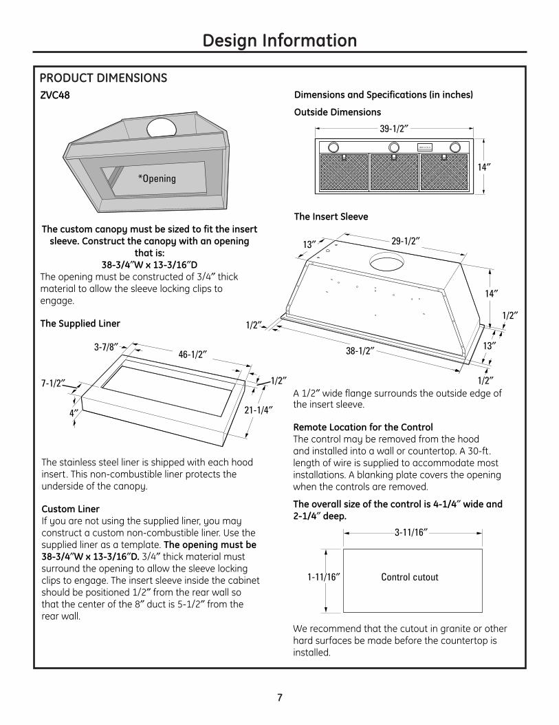
DUCT FITTINGSUse this chart to compute maximum permissible lengths forduct runs to outdoors.
NOTE: Do not exceed maximumpermissible equivalent lengths!
Maximum duct length:100 foot for 8″ round duct
Flexible ducting:If flexible metal ducting is used, all the equivalent feet values in the table should be doubled. The flexible metal duct should be straight and smooth andextended as much as possible.
DO NOT use flexible plastic ducting.
NOTE: Any home ventilation system, such as a ventilation hood,may interrupt the proper flow ofcombustion air and exhaustrequired by fireplaces, gas furnaces, gas water heaters andother naturally vented systems. To minimize the chance of interruption of such naturally vented systems, follow the heating equipment manufacturer’sguidelines and safety standardssuch as those published by NFPAand ASHRAE.
This Hood Must Use an 8″ Round Duct.
9
Advance PlanningTotal
Equivalent Quantity EquivalentDuct Piece Dimensions Length* Used Length
Round, 1 ft.straight (per foot
length)
3-1/4″ x 12″ 1 ft. 3-1/4″ x 24″ (per footstraight length)
8″ round90° elbow 17 ft.
8″ round45° elbow 10 ft.
3-1⁄4″ x 10″ 14 ft.3-1⁄4″ x 12″ 15 ft.90° elbow
3-1/4″ x 10″ 8 ft.3-1/4″ x 12″ 9 ft.45° elbow
3-1/4″ x 10″ 33 ft.3-1/4″ x 12″ 36 ft.90° flat elbow
8″ to 3-1/4″ x 10″ 2 ft.8″ to 3-1/4″ x 12″ 2 ft.or 3-1/4″ x 10″ transition 2 ft.
3-1/4″ x 10″ to 8″ 2 ft.3-1/4″ x 12″ to 8″ 2 ft.round transition
8″ to 3-1/4″ x 10″ 7 ft.8″ to 3-1/4″ x 12″ 6 ft.transition 90° elbow
3-1/4″ x 10″ to 8″ 5 ft.3-1/4″ x 12″ to 8″ 5 ft.round transition 90° elbow
8″ roundwall capwith damper 32 ft. with damper
3-1/4″ x 12″ wall capwith damper 26 ft. with damper
8″ roundroof cap 44 ft.
3-1/4″ x 10″ wall cap w/ damper 24 ft.round roof vent
*Actual length of straight duct plusduct fitting equivalent. Equivalentlength of duct pieces are based on actual tests conducted by GEEvaluation Engineering and reflectrequirements for good ventingperformance with any ventilationhood.
Total Duct Run

10
Installation Preparation
TOOLS AND MATERIALS REQUIRED(NOT SUPPLIED)
Pencil and tape measure
Wire cutter/stripperStep ladder
Wire nuts
Phillips and flat bladescrewdrivers
Strain relief
Spirit level
Flashlight
Safety glasses 8″ ducting andcaps as needed
Aluminizedduct tape
1/4″ pivotinghex socket
REMOVE THE PACKAGING
CAUTION: Wear gloves to protect against sharp edges.
ATTENTION : Portez des gants pour éviter les blessures causées par les tranchants.
CAUTION: LIFT THE INSERT SLEEVE OUT OF THE BOX BY GRASPING THE SIDES.
ATTENTION : SOULEVEZ LE MANCHON INTÉRIEUR DE LA BOÎTE EN SAISISSANT SES CÔTÉS.
1. Open hood carton.2. Remove the liner, foam and cardboard.
3. Remove the tape securing the filters to the insertsleeve, lift the tabs and remove the filters.
4. Unscrew the 5 nuts securing the damper ventplate assembly, and remove it from the insertsleeve. Set the 5 nuts and the damper vent plateassembly aside, as you will be re-installing it laterin the installation process.
5. Remove the screws attaching the insert sleeve tothe mounting board. Discard the screws.
6. Grasp the insert sleeve by the outside edges, andlift straight up and out of the carton.NOTE: Do not lift the insert sleeve by the blowermotor.
7. Remove and properly discard the plastic wrapping.8. Remove the parts box and other packaging.
Electric drill andappropriate bits
1″ conduit (for remotemounting only)
Gloves
3/8″ socket/nut driver
Knife
Plumb line
Silicone
Needle-nose pliers

11
Installation Preparation
PARTS PROVIDEDLocate the parts packed with the hood.
CHECK INSTALLATION HARDWARE
Count screws/components. Screws shown actual size.
Hood liner (packed inseparate carton)
Blanking plate forremote control
opening*
6 woodscrews forhood liner
8 woodscrews for
insertsleeve
5 nuts for damper plateassembly
(not located in hardwarebag–you must save nuts
when you remove damperplate from inset hood
while unpacking parts)
Blower motor(Models ZVC30LSS and ZVC36LSS)
Insert sleeve
Filters
2 wing nutswith lock
washers forblower motor
*NOTE: To be used on custom hoodwhen controls areremotely mounted.
Damper plate
Control wall bracket
Controlmounting
plate
2 mounting platescrews
30 ft. of 4-wire cord (straight-pinned) with connectorNOTE: Not for
telecommunications(telephone) network.
2 wallbracketscrews
Dual blower motor(Model ZVC48LSS)
Controlmountingbracket
6 insert sleeve chassisplugs, 1 (optional) housewire hole plug, 2 rubber
grommets, 4 insert sleevewashers
REMOTE MOUNTING OF THE CONTROL (WIRED)

12
DUCTWORK, WIRING LOCATIONSDetermine the exact location of the insertsleeve. Mark the exact centerline location.The ceiling structure must be capable ofsupporting the weight of the insert sleeve(approximately 100 pounds) and anyinadvertent user contact loads.• Measure from the top of the cooking
surface to the bottom edge of the insertsleeve. Add insert sleeve installation height.Mark that location.
• Use a level to draw a straight horizontalpencil line on the wall.
NOTE: House duct should drop to 11-1/2″above bottom edge of insert sleeve.Location of house duct is importantbecause it must align with vent of damper plate assembly.
Ceiling ducting:If ductwork will vent straight up to the ceiling:• Use a level to draw a centerline straight up
to the ceiling.• On the ceiling, measure 5-1/2″ from
the back wall to the centerline of an 8-1/2″ hole.
Wall Ducting:If ductwork will vent to the rear:• Use a level to draw a centerline straight
up to the ceiling.• Measure at least 16″ above the pencil line
that indicates the bottom installation height,to the centerline of an 8-1/2″ dia. duct hole.(Hole may be elongated for duct elbow.)
HOUSE WIRING LOCATION:• The junction box is located inside the top left
side of the hood.• Wiring should enter the back wall at least
15″ above the bottom of the insert sleeve,and within 6″ of the left side of thecenterline.
16″ above pencilline indicatingbottom of hood
5-1/2″ fromrear wall tocenterline
30″ Min.36″ Max.installationheight
36″ fromfloor tocountertop
Wall Installation Preparation
30″ Min.36″ Max.installationheight
36″ fromfloor tocountertop
Front viewSide view
11-1/2″
4″ liner height
11-1/2″
16″ above pencilline indicatingbottom of hood
4″ liner height

13
Plan the Location of the Hood and DuctworkThe ceiling structure must be capable of supporting theweight of the insert sleeve (approximately 100 pounds)and any inadvertent user contact loads. • Use a plumb bob to check the location. The
countertop/cooktop below the insert sleeve must be centered with the insert sleeve.
• The insert sleeve should extend beyond the front andrear edge of the cooking appliance.
• The insert sleeve in the ceiling must be centered leftto right over the cooktop.
CONSTRUCT CEILING SUPPORT (for Island Installation)
Island Installation Preparation
Ceiling
Hoodductingcenterline
Cooktop
Countertop
Front
Front view
Align withcenter ofcooktop Side view
30″ Min.36″ Max.installationheight
30″ Min.36″ Max.installationheight

14
Installation Preparation
REMOTE MOUNTING OF THE CONTROL(WIRED)
WARNING: Disconnect electricalpower from unit before beginning remote controlinstallation. Failure to do so could result in personalinjury or damage to the electrical controls.
AVERTISSEMENT : Il fautdébrancher l’alimentation électrique de l’appareilavant de commencer l’installation de la commande à distance. Il faut suivre cette directive pour éviterdes blessures ou endommager les commandesélectriques.
REMOTE LOCATION FOR CONTROLThe control can be removed from the hood andinstalled in a backsplash or countertop. • A cover plate is provided to cover the opening in
the hood when the control is removed.• A 30-ft. length of 4-wire cord is supplied to
accommodate most installations. Because only 30-ft. of cord is provided, careful considerationmust be given to the location of the remotelymounted control.
NOTE: Not for telecommunication (telephone)network.• The cord must be routed through the holes in the
insert sleeve, and the rubber grommets put intoplace around the cord.
NOTE: On the ZVC30 and ZVC36 models, the cordneeds to be routed through the holes in the insertsleeve before the damper plate is installed.• Route the cord through the conduit to reach the
installation location of the control.
1-11/16″
3-11/16″
Control cutout

15
Installation Preparation
REMOTE MOUNTING OF THE CONTROL(WIRED) (CONT.)
COUNTERTOP
1. Cut out opening in the countertop. Cutoutdimensions are 1-11/16″ x 3-11/16″.
2. Loosen the 4 thumbscrews and remove the controlfrom the insert sleeve. Replace the control with theblanking plate provided.
3. Attach the mounting plate to the back of thecontrol with the 2 mounting plate screws.
4. Pull the 4-wire cord through the opening in thecountertop, and through the back of the mountingbracket.
NOTES: Use provided cable or cable designated bythe National Electrical Code, NFPA/ANSI 70, or localcodes. Not for telecommunication (telephone)network.5. Connect the 4-wire cord to the jack of the
connector on the control.6. Press the control firmly into the mounting bracket
so that the clips engage. 7. Apply silicone around the cutout opening.8. Insert the control into the cutout opening.
WALL MOUNT
1. Cut out opening into the wall surface. Cutoutdimensions are 1-11/16″ x 3-11/16″.
2. Loosen the 4 thumbscrews and remove thecontrol from the insert sleeve. Replace the control with the blanking plate provided.
3. Attach the mounting plate to the back of thecontrol with the 2 mounting plate screws.
4. Pull the 4-wire cord through the opening in the wall, the wall bracket and the back of themounting bracket.
NOTE: Use provided cable or cable designated bythe National Electrical Code, NFPA/ANSI 70, or localcodes. Not for telecommunication (telephone)network.
5. Connect the mounting bracket to the wall bracketusing the two wall bracket screws. Only start thefirst 1–2 threads of the screws into the wall, asyou want to leave a gap between the twobrackets to account for the wall thickness.
6. Raise the tabs on the mountingbracket so the bracket will fitthrough the wall opening.
7. Angle the mounting and wallbrackets and slide them through the wall cutout.
NOTE: Attach a string to the brackets, so you canretrieve them from behind the wall if dropped.
8. Flatten tabs on mounting bracket so they areflush with the wall surface, and tighten the wallbracket screws to pull the wall bracket flangesflush with the backside surface of the wall.
9. Connect the 4-wire cord to the jack of theconnector on the control.
10. Press the control firmly into the mounting bracket so that the clips engage.
4-wire cord
Mounting bracket
Screws
Connector
Apply silicone aroundcutout opening
Mounting plate
Control
4-wire cordScrews
Jack
Mountingplate
ControlWall bracket
Mountingbracket
Tabs

16
Installation Instructions
STEP 1 INSTALL HOOD LINER
1. Frame the cutout opening to fit the liner. NOTE: The opening support must be 3/4″ thickwood to accept the liner installation screws.
2. Slide the liner up and into the opening until flushwith bottom edges.
3. Secure the liner to the cabinet with 6 screwsprovided.
17
Installation Instructions
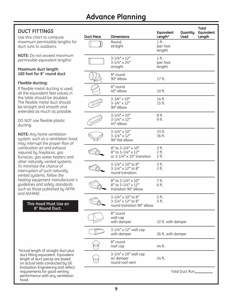
STEP 2 CONNECT ELECTRICALVerify that power is turned off at the source.
WARNING: If house wiring is not 2-wire with a ground wire, an electrician will need to convert existing wiring to meet these specs. When house wiring is aluminum, be sure to use U.L. approved anti-oxidant compound and aluminum-to-copper connectors.
AVERTISSEMENT :Si le câblage de la maison n’est pas un câblage à deux fils avec un fil de terre, un électricien doit convertir votre câblage existant à cescaractéristiques techniques. Si le câblage de votremaison est en aluminium, assurez-vous d’utiliser un composé anti-oxydant approuvé et des raccords aluminium à cuivre.
1. Place insert sleeve on padded, yet stable, surfacebelow cutout (can use flattened carton to padsurface).
2. Remove the junction box cover.
3. Pull house wires through wall of insert sleeve andattach the strain relief. Thread the house wirethrough the junction box.
4. Connect white leads to branch circuit white lead.5. Connect black leads to branch circuit black lead.6. Connect green/yellow leads to branch circuit green
lead.7. Secure all connections with wire nuts on each
electrical connector.
8. Carefully push wires into junction box and replacecover.
9. Secure junction box cover with original screws.
Connect
Wires
Screws
Cover

18
Installation Instructions
1. Tuck the house wiring out of the way.2. Install the insert sleeve into the cutout opening of
custom cabinet frame.
3. Push the insert sleeve straight up through thecutout opening until the temporary locking clipsengage. The locking clips are designed to hold theinsert sleeve in place until it is secured with screws.
NOTE: The locking clips are not designed to supportall of the weight of the insert sleeve. Do not leave theinsert sleeve unattended until screws have beeninserted.
4. Align 8″ duct to exhaust opening of insert sleeveand seal with aluminum tape.
NOTE: House duct should drop to 11-1/2″ abovebottom edge of insert sleeve or the bottom of the3/4″ cabinet base.
5. Tape the 4 washers in place over the outside of the 4 front and back holes of the insert sleeve.The washers are designed to be located betweenthe insert sleeve and the 3/4″ cabinet surface.
6. Press the sleeve up firmly and secure with the 8 screws provided. The insert sleeve should be flush with the liner and have no visible gaps.
NOTE: It is IMPORTANT to install front mounting screw. The front screw hole is difficult to see and may require you to place your head into the cutoutopening to locate.
STEP 3 INSTALL INSERT SLEEVE
Clip
Aluminumtape

19
Installation Instructions
STEP 4 INSTALL DAMPER PLATE
1. Pick up damper plate assembly and rotate so thatvent side is up and bracket is located on left as youstand facing hood.
2. Insert damper plate assembly into insert sleeveand carefully align with 8″ house duct.
3. Secure damper plate assembly by placing nuts on bolts and tightening with socket or wrench.
Bolts

20
Installation Instructions
STEP 5 INSTALL BLOWER MOTOR
1. Pick up blower motor and rotate so tabs align with damper plate bracket.
2. Insert blower motor into insert sleeve throughcutout opening of custom cabinet frame.
3. Place blower motor on damper plate assembly by sliding blower motor tabs into slots of damperplate assembly.
4. While holding blower motor in place, lift right sideso that blower motor bolt holes align with boltsprotruding from damper plate assembly andsecure with lock washers and wing nuts (handtighten).
STEP 6 CONNECT WIRING HARNESSNOTE: On ZVC48, there are three routing clips and two wiring harnesses to connect.
1. Locate both ends of wiring harness.2. Connect wiring harness by inserting male into
female opening.
3. Carefully route wiring harness and ground wirethrough two clips attached to blower plateassembly.
Wiringharness
Brackets

21
Installation Instructions
STEP 7 INSTALL FILTERS1. Remove protective film from the filters.
2. Tip the filter into the back tab slots and lift up.While maintaining slight backward pressure on filter, open clip and press into place with two hands.
3. To remove, support filter with one hand whilepulling filter clip down with the other.
STEP 8 FINALIZE INSTALLATION1. Check to be sure all tape and packaging
materials have been removed.2. Refer to Owner’s Manual for operating
instructions.
Clip
Clip

22
Notes

23
Notes

Note: While performing installations described in this book,safety glasses or goggles should be worn.
For Monogram® local service in your area, call 1.800.444.1845.Note: Product improvement is a continuing endeavor atGeneral Electric. Therefore, materials, appearance andspecifications are subject to change without notice.
GE Consumer & IndustrialGE Appliances General Electric Company Louisville, KY 40225ge.com
©2006 GE CompanyPrinted in Italy