Embed Size (px)
Citation preview
13INSTALLATIONEN
GLISH
InSTALLATIOnInstallation OverviewPlease read the following installation instructions first after purchasing this product or transporting it to another location.
Check and choose the proper location
Plug in the power cordConnect the range to gas Engage the anti-tip device Test run
Install anti-tip device Level the range Connect electric range
Conduit connection plate
Black White RedTerminal block
240 V or 208 V
Pressure regulator
Product SpecificationsThe appearance and specifications listed in this manual may vary due to constant product improvements.
Oven range Models LUTD4919SnDescription Dual Fuel Double Oven Range
Electrical requirements 6.9 kW 120/240 VAC or 5.2kW 120/208 VAC
Exterior Dimensions29 7/8" (W) x 37 59/64" (H) x 28 15/16" (D) (D with door closed)
75.9 cm (W) x 96.3 cm (H) x 73.5 cm (D) (D with door closed)
Height to cooking surface 36" (91.4 cm)
net weight 196.2 lb (89.0 kg)
Total capacityUpper Oven: 3.0 cu. ft.
Lower Oven: 4.3 cu. ft.
Total cap.: 7.3 cu. ft.

14 INSTALLATION
Before Installing the range
WArnInGTip - Over HazardA child or adult can tip the range and be killed. Verify the anti-tip bracket has been installed. Ensure the anti-tip bracket is engaged when the range is moved. Do not operate the range without the anti-tip bracket in place. Failure to follow these instructions can result in death or serious burns to children and adults.
To check that leveling leg is inserted into anti-tip bracket, grasp the top rear edge of the range and carefully attempt to tilt it forward. Anti-tip
bracket
Leveling leg
If you did not receive an anti-tip bracket with your purchase, call 1-800-984-6306 to receive one at no charge.
WArnInG • The information in this manual should be followed exactly. Failure to do so may result in fire, electrical shock, property damage, personal injury, or death.
• Wear gloves during the installation procedure. Failure to do so can result in bodily injury.
• Make sure no parts came loose during shipping.
In the Commonwealth of Massachusetts • This product must be installed by a licensed plumber or gas fitter.
• When using ball type gas shut-off valves, they must be the T-handle type.
• When using a flexible gas connector, it must not exceed 3 feet in length.
nOTE • Observe all governing codes and ordinances.
• Have the installer show you the location of the circuit breaker or fuse. Mark it for easy reference.
• As when using any appliance generating heat, there are certain safety precautions you should follow.
• Be sure your range is installed and grounded properly by a qualified installer or service technician according to the installation instructions.
• Any adjustment and service should be performed only by qualified gas range installers or service technicians.
15INSTALLATIONEN
GLISH
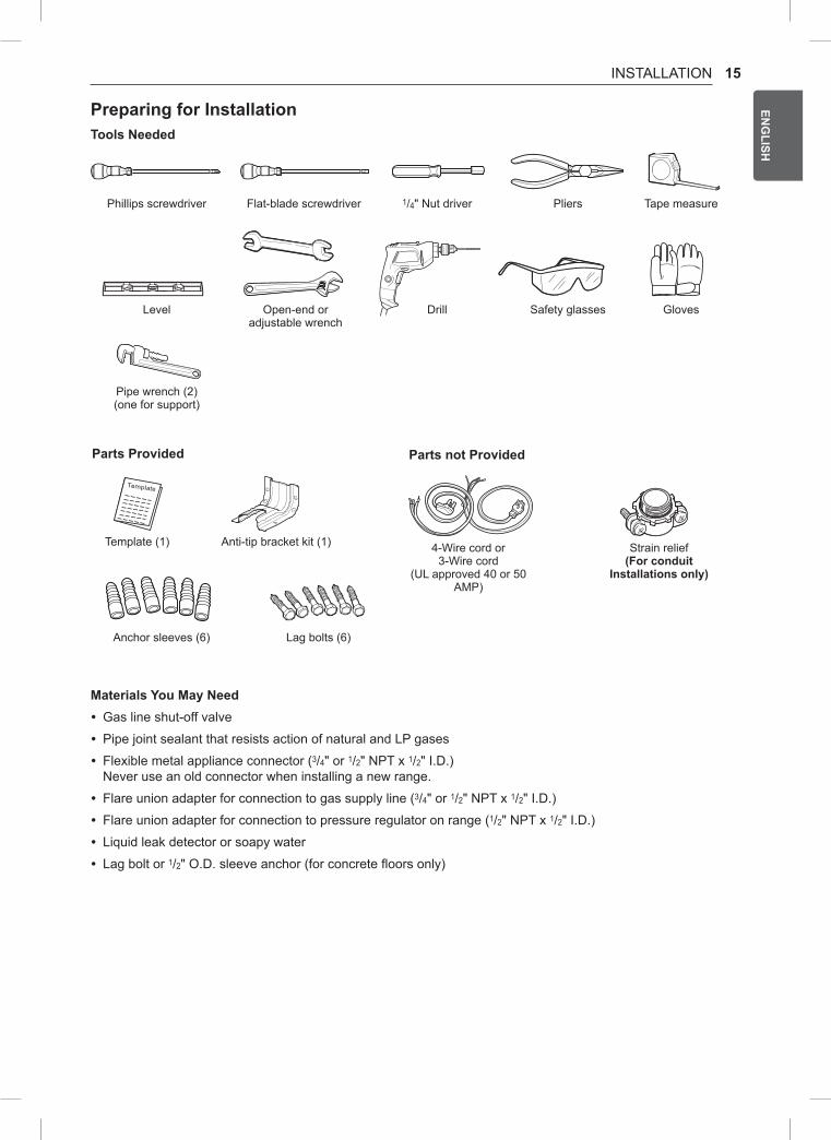
Preparing for InstallationTools needed
Parts Provided
Template (1)
Parts not Provided
4-Wire cord or 3-Wire cord
(UL approved 40 or 50 AMP)
Strain relief(For conduit
Installations only)
Anti-tip bracket kit (1)
Anchor sleeves (6) Lag bolts (6)
Phillips screwdriver
Level
Pipe wrench (2)(one for support)
Flat-blade screwdriver
Open-end or adjustable wrench
1/4" Nut driver
Drill
Pliers
Safety glasses
Tape measure
Gloves
Materials You May need • Gas line shut-off valve
• Pipe joint sealant that resists action of natural and LP gases
• Flexible metal appliance connector (3/4" or 1/2" NPT x 1/2" I.D.) Never use an old connector when installing a new range.
• Flare union adapter for connection to gas supply line (3/4" or 1/2" NPT x 1/2" I.D.)
• Flare union adapter for connection to pressure regulator on range (1/2" NPT x 1/2" I.D.)
• Liquid leak detector or soapy water
• Lag bolt or 1/2" O.D. sleeve anchor (for concrete floors only)
16 INSTALLATION
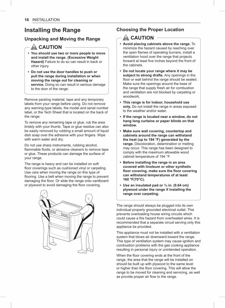
Installing the rangeUnpacking and Moving the range
CAUTIOn • You should use two or more people to move and install the range. (Excessive Weight Hazard) Failure to do so can result in back or other injury.
• Do not use the door handles to push or pull the range during installation or when moving the range out for cleaning or service. Doing so can result in serious damage to the door of the range.
Remove packing material, tape and any temporary labels from your range before using. Do not remove any warning-type labels, the model and serial number label, or the Tech Sheet that is located on the back of the range.
To remove any remaining tape or glue, rub the area briskly with your thumb. Tape or glue residue can also be easily removed by rubbing a small amount of liquid dish soap over the adhesive with your fingers. Wipe with warm water and dry.
Do not use sharp instruments, rubbing alcohol, flammable fluids, or abrasive cleaners to remove tape or glue. These products can damage the surface of your range.
The range is heavy and can be installed on soft floor coverings such as cushioned vinyl or carpeting. Use care when moving the range on this type of flooring. Use a belt when moving the range to prevent damaging the floor. Or slide the range onto cardboard or plywood to avoid damaging the floor covering.
Choosing the Proper Location
CAUTIOn • Avoid placing cabinets above the range. To minimize the hazard caused by reaching over the open flames of operating burners, install a ventilation hood over the range that projects forward at least five inches beyond the front of the cabinets.
• Do not locate your range where it may be subject to strong drafts. Any openings in the floor or wall behind the range should be sealed. Make sure the openings around the base of the range that supply fresh air for combustion and ventilation are not blocked by carpeting or woodwork.
• This range is for indoor, household use only. Do not install the range in areas exposed to the weather and/or water.
• If the range is located near a window, do not hang long curtains or paper blinds on that window.
• Make sure wall covering, countertop and cabinets around the range can withstand the heat (up to 194 °F) generated by the range. Discoloration, delamination or melting may occur. This range has been designed to comply with the maximum allowable wood cabinet temperature of 194 °F.
• Before installing the range in an area covered with linoleum or other synthetic floor covering, make sure the floor covering can withstand temperatures of at least 160 °F(70°C).
• Use an insulated pad or 1/4 in. (0.64 cm) plywood under the range if installing the range over carpeting.
The range should always be plugged into its own individual properly grounded electrical outlet. This prevents overloading house wiring circuits which could cause a fire hazard from overheated wires. It is recommended that a separate circuit serving only this appliance be provided.
This appliance must not be installed with a ventilation system that blows air downward toward the range. This type of ventilation system may cause ignition and combustion problems with the gas cooking appliance resulting in personal injury or unintended operation.
When the floor covering ends at the front of the range, the area that the range will be installed on should be built up with plywood to the same level or higher than the floor covering. This will allow the range to be moved for cleaning and servicing, as well as provide proper air flow to the range.
17INSTALLATIONEN
GLISH
Mobile Home - Additional Installation requirementsThe installation of this range must conform to the Manufactured Home Construction and Safety Standard, Title 24 CFR, Part 3280 (formerly the Federal Standard for Mobile Home Construction and Safety, Title 24, HUD Part 280), or when such standard is not applicable, the Standard for Manufactured Home Installations, ANSI A225.1/NFPA 501A or with local codes.
• When this range is installed in a mobile home, it must be secured to the floor during transit. Any method of securing the range is adequate as long as it conforms to the standards listed above.
• A four-wire power supply cord or cable must be used in a mobile home installation.
18 INSTALLATION
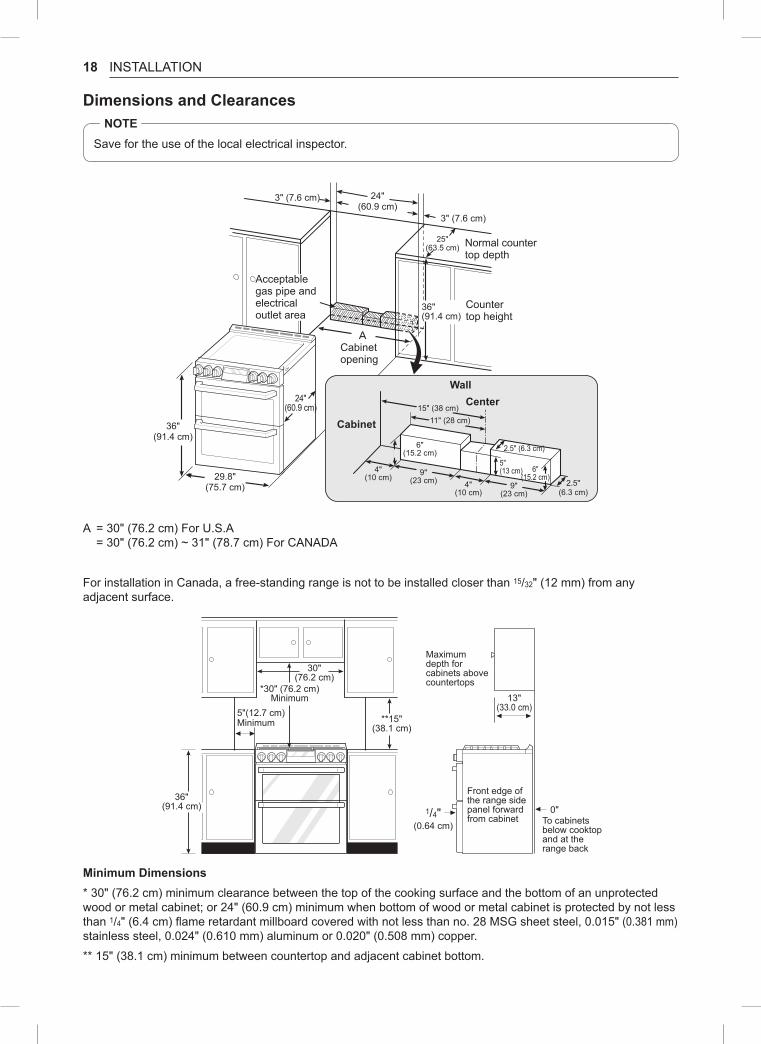
Dimensions and ClearancesnOTE
Save for the use of the local electrical inspector.
3" (7.6 cm) 24"(60.9 cm)
24"(60.9 cm)
36"(91.4 cm)
29.8"(75.7 cm)
15" (38 cm)11" (28 cm)
2.5" (6.3 cm)
2.5"(6.3 cm)
9"(23 cm)
4"(10 cm)
9"(23 cm)
4"(10 cm)
6"(15.2 cm)
5"(13 cm) 6"
(15.2 cm)
25"(63.5 cm)
36"(91.4 cm)
3" (7.6 cm)
Acceptable gas pipe and electrical outlet area
Normal counter top depth
Counter top height
Cabinet opening
WallCenter
Cabinet
A = 30" (76.2 cm) For U.S.A = 30" (76.2 cm) ~ 31" (78.7 cm) For CANADA
For installation in Canada, a free-standing range is not to be installed closer than 15/32" (12 mm) from any adjacent surface.
30"(76.2 cm)
36"(91.4 cm)
**15"(38.1 cm)
*30" (76.2 cm)Minimum 13"
(33.0 cm)
Maximum depth for cabinets above countertops
Front edge of the range side panel forward from cabinet
0"To cabinets below cooktop and at the range back
1/4"(0.64 cm)
5"(12.7 cm)Minimum
Minimum Dimensions* 30" (76.2 cm) minimum clearance between the top of the cooking surface and the bottom of an unprotected wood or metal cabinet; or 24" (60.9 cm) minimum when bottom of wood or metal cabinet is protected by not less than 1/4" (6.4 cm) flame retardant millboard covered with not less than no. 28 MSG sheet steel, 0.015" (0.381 mm) stainless steel, 0.024" (0.610 mm) aluminum or 0.020" (0.508 mm) copper.
** 15" (38.1 cm) minimum between countertop and adjacent cabinet bottom.
19INSTALLATIONEN
GLISH
Installing the Anti-tip Device
Anti-tip bracket
Leveling leg
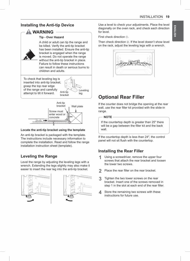
WArnInGTip - Over HazardA child or adult can tip the range and be killed. Verify the anti-tip bracket has been installed. Ensure the anti-tip bracket is engaged when the range is moved. Do not operate the range without the anti-tip bracket in place. Failure to follow these instructions can result in death or serious burns to children and adults.
To check that leveling leg is inserted into anti-tip bracket, grasp the top rear edge of the range and carefully attempt to tilt it forward.
Wall plateAnti-tip bracket
Screw must enter wood or concrete
Locate the anti-tip bracket using the templateAn anti-tip bracket is packaged with the template. The instructions include necessary information to complete the installation. Read and follow the range installation instruction sheet (template).
Leveling the rangeLevel the range by adjusting the leveling legs with a wrench. Extending the legs slightly may also make it easier to insert the rear leg into the anti-tip bracket.
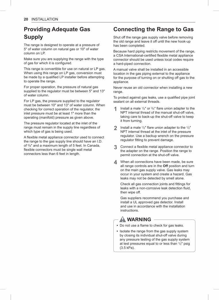
Use a level to check your adjustments. Place the level diagonally on the oven rack, and check each direction for level.
First check direction .
Then check direction . If the level doesn’t show level on the rack, adjust the leveling legs with a wrench.
1
2
Optional rear FillerIf the counter does not bridge the opening at the rear wall, use the rear filler kit provided with the slide-in range.
nOTEIf the countertop depth is greater than 25" there will be a gap between the filler kit and the back wall.
If the countertop depth is less than 24", the control panel will not sit flush with the countertop.
Installing the rear Filler1 Using a screwdriver, remove the upper four
screws that attach the rear bracket and loosen the lower two screws.
2 Place the rear filler on the rear bracket.
3 Tighten the two lower screws on the rear bracket. Insert one of the screws removed in step 1 in the slot at each end of the rear filler.
4 Store the remaining two screws with these instructions for future use.
20 INSTALLATION
Providing Adequate Gas SupplyThe range is designed to operate at a pressure of 5" of water column on natural gas or 10" of water column on LP.
Make sure you are supplying the range with the type of gas for which it is configured.
This range is convertible for use on natural or LP gas. When using this range on LP gas, conversion must be made by a qualified LP installer before attempting to operate the range.
For proper operation, the pressure of natural gas supplied to the regulator must be between 5" and 13" of water column.
For LP gas, the pressure supplied to the regulator must be between 10" and 13" of water column. When checking for correct operation of the regulator, the inlet pressure must be at least 1" more than the operating (manifold) pressure as given above.
The pressure regulator located at the inlet of the range must remain in the supply line regardless of which type of gas is being used.
A flexible metal appliance connector used to connect the range to the gas supply line should have an I.D. of 5/8" and a maximum length of 5 feet. In Canada, flexible connectors must be single wall metal connectors less than 6 feet in length.
Connecting the range to GasShut off the range gas supply valve before removing the old range and leave it off until the new hook-up has been completed.
Because hard piping restricts movement of the range, a CSA International-certified flexible metal appliance connector should be used unless local codes require a hard-piped connection.
A manual valve shall be installed in an accessible location in the gas piping external to the appliance for the purpose of turning on or shutting off gas to the appliance.
Never reuse an old connector when installing a new range.
To protect against gas leaks, use a qualified pipe joint sealant on all external threads.
1 Install a male 1/2" or 3/4" flare union adapter to the NPT internal thread of the manual shut-off valve, taking care to back-up the shut-off valve to keep it from turning.
2 Install a male 1/2" flare union adapter to the 1/2" NPT internal thread at the inlet of the pressure regulator. Use a backup wrench on the pressure regulator fitting to prevent damage.
3 Connect a flexible metal appliance connector to the adapter on the range. Position the range to permit connection at the shut-off valve.
4 When all connections have been made, be sure all range controls are in the Off position and turn on the main gas supply valve. Gas leaks may occur in your system and create a hazard. Gas leaks may not be detected by smell alone.
Check all gas connection joints and fittings for leaks with a non-corrosive leak detection fluid, then wipe off.
Gas suppliers recommend you purchase and install a UL approved gas detector. Install and use in accordance with the installation instructions.
WArnInG • Do not use a flame to check for gas leaks.
• Isolate the range from the gas supply system by closing its individual shut-off valve during any pressure testing of the gas supply system at test pressures equal to or less than 1/2" psig (3.5 kPa).
21INSTALLATIONEN
GLISH
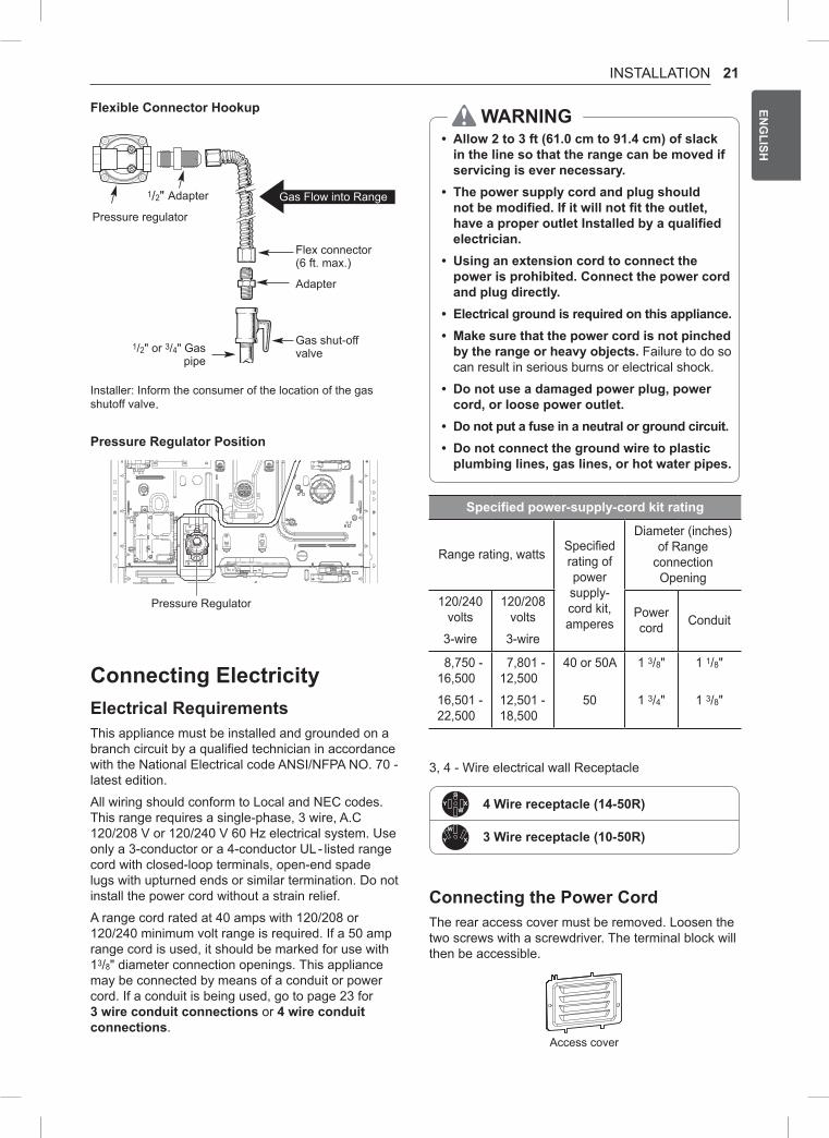
Flexible Connector Hookup
1/2" Adapter
Pressure regulator
Flex connector(6 ft. max.)
Adapter
Gas shut-off valve
1/2" or 3/4" Gas pipe
Gas Flow into Range
Installer: Inform the consumer of the location of the gas shutoff valve.
Pressure regulator Position
Pressure Regulator
Connecting ElectricityElectrical requirementsThis appliance must be installed and grounded on a branch circuit by a qualified technician in accordance with the National Electrical code ANSI/NFPA NO. 70 - latest edition.
All wiring should conform to Local and NEC codes. This range requires a single-phase, 3 wire, A.C 120/208 V or 120/240 V 60 Hz electrical system. Use only a 3-conductor or a 4-conductor UL- listed range cord with closed-loop terminals, open-end spade lugs with upturned ends or similar termination. Do not install the power cord without a strain relief.
A range cord rated at 40 amps with 120/208 or 120/240 minimum volt range is required. If a 50 amp range cord is used, it should be marked for use with 13/8" diameter connection openings. This appliance may be connected by means of a conduit or power cord. If a conduit is being used, go to page 23 for 3 wire conduit connections or 4 wire conduit connections.
WArnInG • Allow 2 to 3 ft (61.0 cm to 91.4 cm) of slack in the line so that the range can be moved if servicing is ever necessary.
• The power supply cord and plug should not be modified. If it will not fit the outlet, have a proper outlet Installed by a qualified electrician.
• Using an extension cord to connect the power is prohibited. Connect the power cord and plug directly.
• Electrical ground is required on this appliance. • Make sure that the power cord is not pinched by the range or heavy objects. Failure to do so can result in serious burns or electrical shock.
• Do not use a damaged power plug, power cord, or loose power outlet.
• Do not put a fuse in a neutral or ground circuit. • Do not connect the ground wire to plastic plumbing lines, gas lines, or hot water pipes.
Specified power-supply-cord kit rating
Range rating, watts Specified rating of power supply-cord kit, amperes
Diameter (inches) of Range
connection Opening
120/240 volts
3-wire
120/208 volts
3-wire
Power cord Conduit
8,750 - 16,500
16,501 - 22,500
7,801 - 12,500
12,501 - 18,500
40 or 50A
50
1 3/8"
1 3/4"
1 1/8"
1 3/8"
3, 4 - Wire electrical wall Receptacle
4 Wire receptacle (14-50r)
3 Wire receptacle (10-50r)
Connecting the Power CordThe rear access cover must be removed. Loosen the two screws with a screwdriver. The terminal block will then be accessible.
Access cover
22 INSTALLATION
Use the cord/conduit connection plate to install the power cord or conduit. Leave the connection plate as installed for power cord installations. Remove the connection plate for conduit installations and use the smaller 11/8 in. (2.8 cm) conduit hole instead of the 13/8 in. (3.5 cm) power cord hole.
Remove the Conduit connection plate
11/8" (2.8 cm) Conduit
13/8" (3.5 cm) Cord
For power cord installations, hook the strain relief over the 13/8 in. (3.5 cm) power cord hole located below the rear of the oven. Insert the power cord through the strain relief and tighten it.
Conduit connection plate
Power cord
Assembling power cord strain relief at the 13/8" opening
For conduit installations, insert the conduit strain relief in the 11/8 in. (2.8 cm) conduit hole. Then install the conduit through the body of the strain relief and fasten the strain relief with its ring.
Cord/Conduit connection plate
Conduit
Ring
Body
Assembling conduit cord strain relief at the 11/8" opening
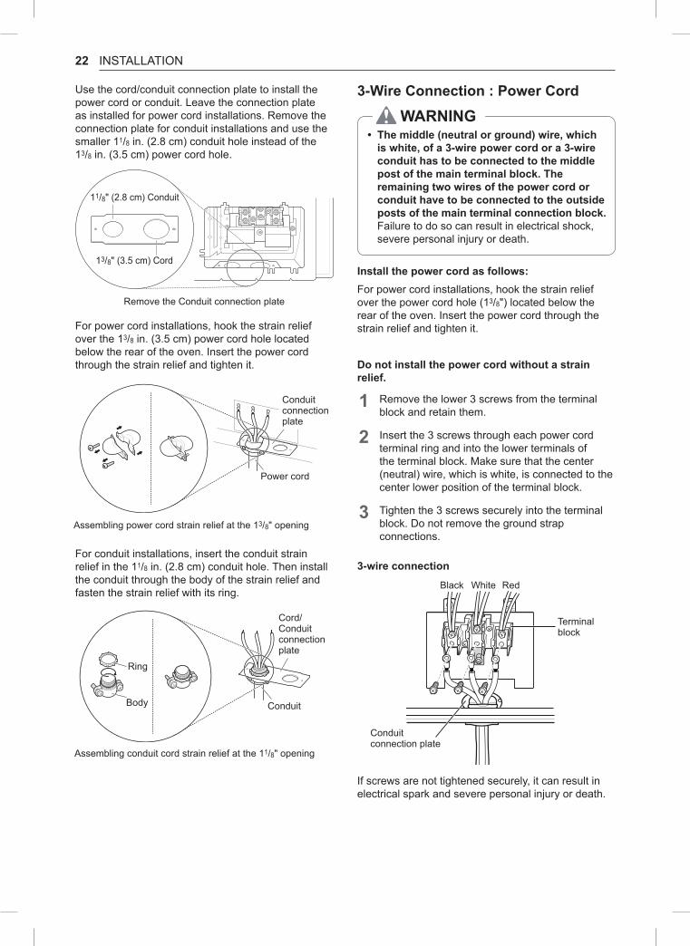
3-Wire Connection : Power Cord
WArnInG • The middle (neutral or ground) wire, which is white, of a 3-wire power cord or a 3-wire conduit has to be connected to the middle post of the main terminal block. The remaining two wires of the power cord or conduit have to be connected to the outside posts of the main terminal connection block. Failure to do so can result in electrical shock, severe personal injury or death.
Install the power cord as follows:For power cord installations, hook the strain relief over the power cord hole (13/8") located below the rear of the oven. Insert the power cord through the strain relief and tighten it.
Do not install the power cord without a strain relief.
1 Remove the lower 3 screws from the terminal block and retain them.
2 Insert the 3 screws through each power cord terminal ring and into the lower terminals of the terminal block. Make sure that the center (neutral) wire, which is white, is connected to the center lower position of the terminal block.
3 Tighten the 3 screws securely into the terminal block. Do not remove the ground strap connections.
3-wire connectionBlack White Red
Terminal block
Conduit connection plate
If screws are not tightened securely, it can result in electrical spark and severe personal injury or death.

23INSTALLATIONEN
GLISH
4-Wire Connection : Power Cord
WArnInG • Only a 4-conductor power-supply cord kit rated 120/208 or 120/240 volts, 50 amperes and marked for use with ranges with closed-loop connectors or opened spade lugs with upturned ends shall be used. The white middle (neutral) wire of the power cord or 4-wire conduit has to be connected to the middle post of the main terminal block. The other two wires of the power cord or conduit have to be connected to the outside posts of the main terminal connection block. The 4th ground wire (green) must be connected to the frame of the range with the ground screw. Failure to do so can result in electrical shock, severe personal injury or death.
Install the power cord as follows:Do not install the power cord without a strain relief.
1 Remove the lower 3 screws from the terminal block and retain them.
2 Remove the ground screw and bend the end of the ground strap up so the slot is over the hole of the center screw removed in step 1.
3 Insert the ground screw into the power cord ground wire (green) terminal ring and secure it to the range frame.
4 Insert the 3 screws through each power cord terminal ring and into the lower terminals of the terminal block. Make sure that the white center (neutral) wire is connected to the center lower position of the terminal block.
5 Tighten the 3 screws securely into the terminal block. The center screw now attaches the bent up ground strap to the block.
4-wire connection
Ground strap
Terminal block
Conduit connection plate
Ground screw
Black White Red
Bend strap up and attach
If screws are not tightened securely, it can result in electrical spark and severe personal injury or death.
3-Wire Connection: ConduitInstall the conduit as follows:Remove the conduit connection plate from the rear of the oven and rotate it. The conduit hole (11/8") must be used.
First, prepare the conduit wires as shown below.
3-Wire
Conduit connection plate
Ground wire
or
4-Wire
Second, install the conduit strain relief.
For conduit installations, purchase a strain relief and insert it in the 11/8 in. (2.8 cm) conduit hole. Then install the conduit through the body of the strain relief and fasten the strain relief with its ring. Reinstall the bracket. For conduit connections: If the wire in the conduit is copper it must be 8 or 10 AWG wiring. If the wire in the conduit is aluminum it must be 6 or 8 AWG wiring.
1 Loosen the lower 3 screws from the terminal block.
2 Insert the bare wire (white/neutral) end through the center terminal block opening. Do not remove the ground strap connections.
3 Insert the two side bare wire ends into the lower left and the lower right terminal block openings. Tighten the 3 screws securely into the terminal block. (approximately 35 - 50 IN-LB)
3-wire connection
Terminal block
Black White Red
Wire ends
Conduit connection plate
If screws are not tightened securely, it can result in electrical spark and severe personal injury or death.
24 INSTALLATION
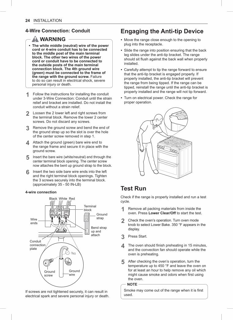
4-Wire Connection: Conduit
WArnInG • The white middle (neutral) wire of the power cord or 4-wire conduit has to be connected to the middle post of the main terminal block. The other two wires of the power cord or conduit have to be connected to the outside posts of the main terminal connection block. The 4th ground wire (green) must be connected to the frame of the range with the ground screw. Failure to do so can result in electrical shock, severe personal injury or death.
1 Follow the instructions for installing the conduit under 3-Wire Connection: Conduit until the strain relief and bracket are installed. Do not install the conduit without a strain relief.
2 Loosen the 2 lower left and right screws from the terminal block. Remove the lower 2 center screws. Do not discard any screws.
3 Remove the ground screw and bend the end of the ground strap up so the slot is over the hole of the center screw removed in step 1.
4 Attach the ground (green) bare wire end to the range frame and secure it in place with the ground screw.
5 Insert the bare wire (white/neutral) end through the center terminal block opening. The center screw now attaches the bent up ground strap to the block.
6 Insert the two side bare wire ends into the left and the right terminal block openings. Tighten the 3 screws securely into the terminal block. (approximately 35 - 50 IN-LB)
4-wire connection
Terminal block
Black White Red
Ground strapWire
ends
Conduit connection plate
Bend strap up and attach
Ground wire
Ground screw
If screws are not tightened securely, it can result in electrical spark and severe personal injury or death.
Engaging the Anti-tip Device • Move the range close enough to the opening to plug into the receptacle.
• Slide the range into position ensuring that the back leg slides under the anti-tip bracket. The range should sit flush against the back wall when properly installed.
• Carefully attempt to tip the range forward to ensure that the anti-tip bracket is engaged properly. If properly installed, the anti-tip bracket will prevent the range from being tipped. If the range can be tipped, reinstall the range until the anti-tip bracket is properly installed and the range will not tip forward.
• Turn on electrical power. Check the range for proper operation.
Test runCheck if the range is properly installed and run a test cycle.
1 Remove all packing materials from inside the oven. Press Lower Clear/Off to start the test.
2 Check the oven’s operation. Turn oven mode knob to select Lower Bake. 350 °F appears in the display.
3 Press Start.
4 The oven should finish preheating in 15 minutes, and the convection fan should operate while the oven is preheating.
5 After checking the oven’s operation, turn the temperature up to 450 °F and leave the oven on for at least an hour to help remove any oil which might cause smoke and odors when first using the oven.nOTE
Smoke may come out of the range when it is first used.

25INSTALLATIONEN
GLISH
Assembling the Surface Burners
CAUTIOnDo not operate the burners without all parts in place.
Place the burner caps and heads on the cooktop. Make sure that the caps and heads are placed in the correct locations. There is one small, one medium, one large, one oval(center), and one extra large burner head and cap.
Center BurnerOval (Center) burner head/cap assembly
Small burner head and cap
Medium burner head and cap
Large burner head and cap
Front of range Extra large burner head and cap
Hole
Electrode
Make sure the hole in the burner head is positioned over the electrode.
Checking Ignition of the Surface BurnersElectric IgnitionSelect a surface burner knob and simultaneously push in and turn to the Lite position. You will hear a clicking sound indicating proper operation of the spark module.
Once the air has been purged from the supply lines the burner should ignite within 4 seconds. After the burner ignites, rotate the knob out of the Lite position. Try each burner in succession until all burners have been checked.
Quality of FlamesThe combustion quality of the burner flames needs to be confirmed visually.
A Yellow flames - Call for service.
B Yellow tips on outer cones - This is normal for LP gas.
C Soft blue flames - This is normal for natural gas.
nOTE • With LP gas, some yellow tipping on outer cones is normal.
Adjusting the Surface Burner to the Low Flame (Simmer) Setting1 Light all surface burners.
2 Turn the knob on the burner being adjusted to Lo.
3 Remove the knob.
4 Insert a small, flat-blade screwdriver into the valve shaft.
nOTEHold the valve shaft with one hand while turning the screw to adjust with the other.
5 Replace the knob.
6 Test the flame stability.
Test 1: Turn the knob from Hi to Lo quickly. If the flame goes out, increase the flame size and test again.
Test 2: With the burner on a Lo setting, open and close the oven door quickly. If the flame is extinguished by the air currents created by the door movement, increase the flame height and test again.
7 Repeat steps 1-6 for each surface burner.


![2. Product specifications - Diagramas dediagramasde.com/diagramas/otros2/02_specifications[1].pdf · 2-1 2. Product specifications 2. Product specifications 2-1. Specifications Information](https://img.pdfslide.us/doc/110x75/5ac0f5e77f8b9ad73f8c5c3a/2-product-specifications-diagramas-1pdf2-1-2-product-specifications-2-product.jpg)