Embed Size (px)
Citation preview
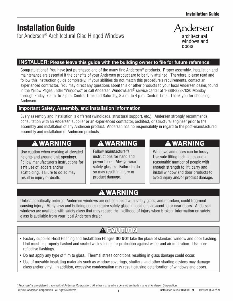
Installation Guide
Every assembly and installation is different (windloads, structural support, etc.). Andersen strongly recommends consultation with an Andersen supplier or an experienced contractor, architect, or structural engineer prior to the assembly and installation of any Andersen product. Andersen has no responsibility in regard to the post-manufactured assembly and installation of Andersen products.
Congratulations! You have just purchased one of the many fine Andersen® products. Proper assembly, installation and maintenance are essential if the benefits of your Andersen product are to be fully attained. Therefore, please read and follow this instruction guide completely. If your abilities do not match this procedure’s requirements, contact an experienced contractor. You may direct any questions about this or other products to your local Andersen dealer, found in the Yellow Pages under “Windows” or call Andersen WindowCare® service center at 1-888-888-7020 Monday through Friday, 7 a.m. to 7 p.m. Central Time and Saturday, 8 a.m. to 4 p.m. Central Time. Thank you for choosing Andersen.
• FactorysuppliedHeadFlashingandInstallationFlangesDO NOT take the place of standard window and door flashing. Unit must be properly flashed and sealed with silicone for protection against water and air infiltration. Use non-reflective flashings.
• Donotapplyanytypeoffilmtoglass.Thermalstressconditionsresultinginglassdamagecouldoccur.
• Useofmovableinsulatingmaterialssuchaswindowcoverings,shutters,andothershadingdevicesmaydamageglass and/or vinyl. In addition, excessive condensation may result causing deterioration of windows and doors.
Unless specifically ordered, Andersen windows are not equipped with safety glass, and if broken, could fragment causing injury. Many laws and building codes require safety glass in locations adjacent to or near doors. Andersen windows are available with safety glass that may reduce the likelihood of injury when broken. Information on safety glass is available from your local Andersen dealer.
Use caution when working at elevated heights and around unit openings. Follow manufacturer’s instructions for safe use of ladders and/or scaffolding. Failure to do so may result in injury or death.
Follow manufacturer’s instructions for hand and power tools. Always wear safety glasses. Failure to do so may result in injury or product damage.
Windows and doors can be heavy. Use safe lifting techniques and a reasonable number of people with enough strength to lift, carry and install window and door products to avoid injury and/or product damage.
“Andersen” is a registered trademark of Andersen Corporation. All other marks where denoted are trade marks of Andersen Corporation. ©2009 Andersen Corporation. All rights reserved. Instruction Guide 105419 M Revised 09/02/09
Installation Guidefor Andersen® Architectural Clad Hinged Windows
1
105419
Parts Included(1) Installation Guide(1) Window Unit (1) Screw Pack(4-6) Corner Gaskets (1) Insect Screen
Metal fasteners and other hardware components may corrode when exposed to preservative treated and fire-retardant treated lumber. Obtain and use the appropriate metal fasteners and hardware as called out by the installation guide to fasten unit to any rough opening made from pressure treated and fire-retardant treated lumber. Failure to use the appropriate materials for the installation may cause a failure resulting in injury, property or product damage.
Supplies Needed•FormableSelf-adheringSillFlashing•Flashing•HouseWrapTape•Sealant•FoamBackerRod•Shims(waterproof) •LowExpandingFoam •DripCap(fullwidth) •Staples•Fasteners (use Stainless Steel if required) - #10 x 1 ½" Screws - 1 ¾" Roofing Nails - #10 x 3" Screws
Tools Needed•SafetyGlasses•TapeMeasure•Level•Hammer•UtilityKnife•Drill/Driver•#2PhillipsBit•7/64"HexWrench•7/16" Wrench•CaulkGun•StapleGun•3/16"DrillBit
Glass
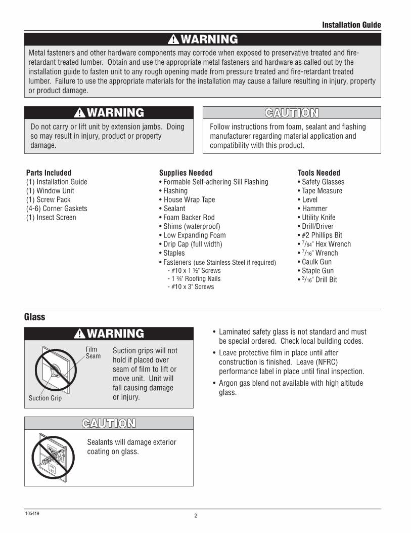
Suction grips will not hold if placed over seam of film to lift or move unit. Unit will fall causing damage or injury.
Sealants will damage exterior coating on glass.
• Laminatedsafetyglassisnotstandardandmustbe special ordered. Check local building codes.
• Leaveprotectivefilminplaceuntilafterconstructionisfinished.Leave(NFRC)performance label in place until final inspection.
• Argongasblendnotavailablewithhighaltitudeglass.
Film Seam
Suction Grip
Donotcarryorliftunitbyextensionjambs.Doingso may result in injury, product or property damage.
Follow instructions from foam, sealant and flashing manufacturer regarding material application and compatibility with this product.
Installation Guide
2
105419
Film Removal
• Removeprotectivefilmfromseamorcornerusingplastic scraper if needed.
• Removeprotectivefilmwithinninemonthsofinstallation and when temperature is above 32° F.
Static created when removing film can ignite flammable materials or cause a shock.
See warning label on glass.
Disposeoffilmimmediatelyafterremoval.Filmmay pose suffocation hazard to children.
Cleaning
Maintenance
Acid solutions used for cleaning masonry or concrete will damage glass, fasteners, hardware, and metal flashing. Protect unit and follow cleaning product instructions carefully. If acid contacts unit, wash all surfaces with water immediately.
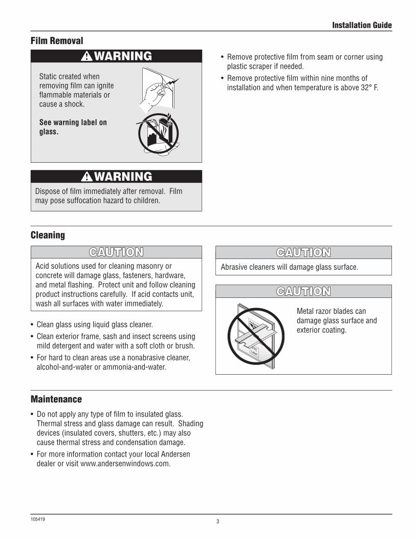
Metal razor blades can damage glass surface and exterior coating.
Abrasive cleaners will damage glass surface.
• Cleanglassusingliquidglasscleaner.• Cleanexteriorframe,sashandinsectscreensusing
mild detergent and water with a soft cloth or brush.• Forhardtocleanareasuseanonabrasivecleaner,
alcohol-and-water or ammonia-and-water.
• Donotapplyanytypeoffilmtoinsulatedglass.Thermal stress and glass damage can result. Shading devices (insulated covers, shutters, etc.) may also cause thermal stress and condensation damage.
• FormoreinformationcontactyourlocalAndersendealer or visit www.andersenwindows.com.
Installation Guide
3
105419
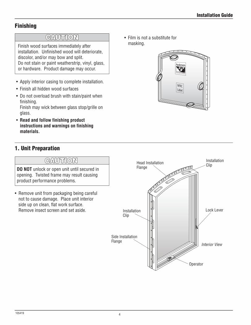
• Removeunitfrompackagingbeingcarefulnot to cause damage. Place unit interior side up on clean, flat work surface. Remove insect screen and set aside.
1. Unit Preparation
Side Installation Flange
Interior View
HeadInstallationFlangeDO NOT unlock or open unit until secured in
opening. Twisted frame may result causing product performance problems.
Installation Clip
Installation Clip
LockLever
Operator
Finishing
Finish wood surfaces immediately after installation. Unfinished wood will deteriorate, discolor, and/or may bow and split.Donotstainorpaintweatherstrip,vinyl,glass,or hardware. Product damage may occur.
• Applyinteriorcasingtocompleteinstallation.• Finishallhiddenwoodsurfaces• Donotoverloadbrushwithstain/paintwhen
finishing. Finish may wick between glass stop/grille on glass.
• Read and follow finishing product instructions and warnings on finishing materials.
• Filmisnotasubstituteformasking.
Installation Guide
4
105419
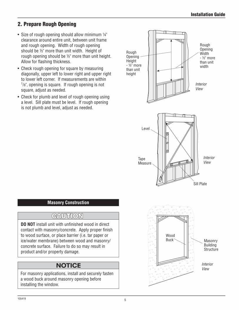
Sill Plate
Tape Measure
Rough Opening Height- ½" more than unit height
Interior View
Interior View
Rough Opening Width - ½" more than unit width
Level
• Sizeofroughopeningshouldallowminimum¼"clearance around entire unit, between unit frame and rough opening. Width of rough opening shouldbe½"morethanunitwidth.Heightofrough opening should be ½" more than unit height. Allow for flashing thickness.
• Checkroughopeningforsquarebymeasuringdiagonally, upper left to lower right and upper right to lower left corner. If measurements are within 1/8", opening is square. If rough opening is not square, adjust as needed.
• Checkforplumbandlevelofroughopeningusinga level. Sill plate must be level. If rough opening is not plumb and level, adjust as needed.
Interior View
2. Prepare Rough Opening
For masonry applications, install and securely fasten a wood buck around masonry opening before installing the window.
Wood Buck Masonry
BuildingStructure
DO NOT install unit with unfinished wood in direct contact with masonry/concrete. Apply proper finish to wood surface, or place barrier (i.e. tar paper or ice/water membrane) between wood and masonry/concrete surface. Failure to do so may result in product and/or property damage.
Masonry Construction
Installation Guide
5
105419
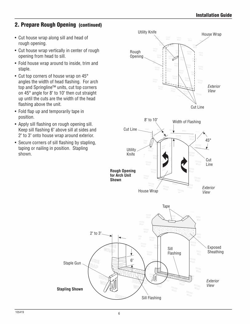
2. Prepare Rough Opening (continued)
• Cuthousewrapalongsillandheadofrough opening.
• Cuthousewrapverticallyincenterofroughopening from head to sill.
• Foldhousewraparoundtoinside,trimandstaple.
• Cuttopcornersofhousewrapon45°angles the width of head flashing. For arch top and Springline™ units, cut top corners on 45° angle for 8" to 10" then cut straight up until the cuts are the width of the head flashing above the unit.
• Foldflapupandtemporarilytapeinposition.
• Applysillflashingonroughopeningsill.Keepsillflashing6"abovesillatsidesand2" to 3" onto house wrap around exterior.
• Securecornersofsillflashingbystapling,taping or nailing in position. Stapling shown.
Utility Knife
UtilityKnife
HouseWrap
HouseWrap
Sill Flashing
Sill Flashing
Staple Gun
2" to 3"
6"
Stapling Shown
Rough Opening for Arch Unit Shown
Exposed Sheathing
CutLine
CutLine
8" to 10"
Tape
Cut Line
Width of Flashing
45°
Rough Opening
Exterior View
Exterior View
Exterior View
Installation Guide
6
105419
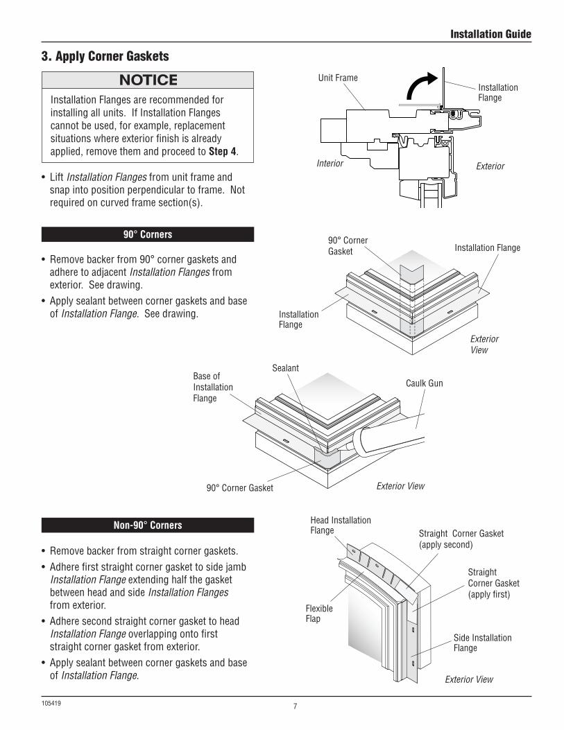
3. Apply Corner Gaskets
• Removebackerfrom90°cornergasketsandadhere to adjacent Installation Flanges from exterior. See drawing.
• Applysealantbetweencornergasketsandbaseof Installation Flange. See drawing.
• Removebackerfromstraightcornergaskets.• Adherefirststraightcornergaskettosidejamb
Installation Flange extending half the gasket between head and side Installation Flanges from exterior.
• AdheresecondstraightcornergaskettoheadInstallation Flange overlapping onto first straight corner gasket from exterior.
• Applysealantbetweencornergasketsandbaseof Installation Flange.
90° Corners
Non-90° Corners
Exterior View
Exterior View
Exterior View
90° Corner Gasket
90° Corner Gasket
BaseofInstallation Flange
Straight Corner Gasket (apply first)
Straight Corner Gasket (apply second)
Installation Flange
Side Installation Flange
Installation Flange
HeadInstallationFlange
Flexible Flap
Sealant
Caulk Gun
Installation Flanges are recommended for installing all units. If Installation Flanges cannot be used, for example, replacement situations where exterior finish is already applied, remove them and proceed to Step 4.
• LiftInstallation Flanges from unit frame and snap into position perpendicular to frame. Not required on curved frame section(s).
Installation Flange
Unit Frame
Interior Exterior
Installation Guide
7
105419
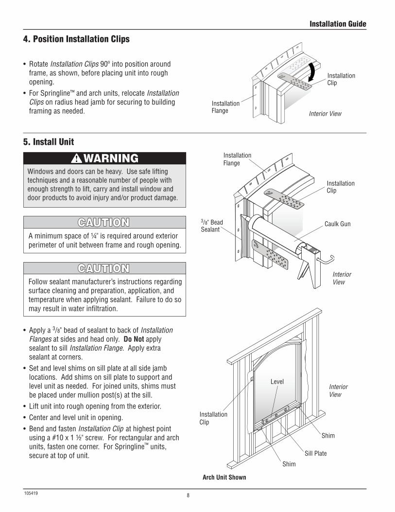
4. Position Installation Clips
Installation Clip
Interior View
• RotateInstallation Clips 90º into position around frame, as shown, before placing unit into rough opening.
• ForSpringline™ and arch units, relocate Installation Clips on radius head jamb for securing to building framing as needed.
Installation Flange
5. Install Unit
• Applya3/8" bead of sealant to back of Installation Flanges at sides and head only. Do Not apply sealant to sill Installation Flange. Apply extra sealant at corners.
• Setandlevelshimsonsillplateatallsidejamblocations. Add shims on sill plate to support and level unit as needed. For joined units, shims must be placed under mullion post(s) at the sill.
• Liftunitintoroughopeningfromtheexterior.• Centerandlevelunitinopening.• BendandfastenInstallation Clip at highest point
using a #10 x 1 ½" screw. For rectangular and arch units, fasten one corner. For Springline™ units, secure at top of unit.
Aminimumspaceof¼"isrequiredaroundexteriorperimeter of unit between frame and rough opening.
3/8"BeadSealant
Installation Flange
Installation Clip
Caulk Gun
Interior ViewFollow sealant manufacturer’s instructions regarding
surface cleaning and preparation, application, and temperature when applying sealant. Failure to do so may result in water infiltration.
Windows and doors can be heavy. Use safe lifting techniques and a reasonable number of people with enough strength to lift, carry and install window and door products to avoid injury and/or product damage.
Shim
Shim
Sill Plate
Interior View
Level
Arch Unit Shown
Installation Clip
Installation Guide
8
105419
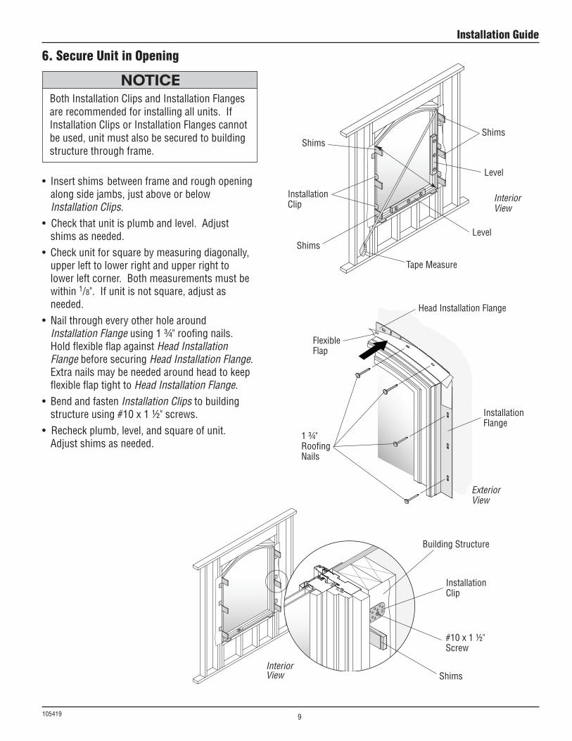
6. Secure Unit in Opening
•Insertshimsbetweenframeandroughopeningalong side jambs, just above or below Installation Clips.
•Checkthatunitisplumbandlevel.Adjustshims as needed.
• Checkunitforsquarebymeasuringdiagonally,upper left to lower right and upper right to lowerleftcorner.Bothmeasurementsmustbewithin 1/8". If unit is not square, adjust as needed.
• NailthrougheveryotherholearoundInstallation Flange using 1 ¾" roofing nails. HoldflexibleflapagainstHead Installation Flange before securing Head Installation Flange. Extra nails may be needed around head to keep flexible flap tight to Head Installation Flange.
• BendandfastenInstallation Clips to building structure using #10 x 1 ½" screws.
•Recheckplumb,level,andsquareofunit.Adjust shims as needed.
BothInstallationClipsandInstallationFlangesare recommended for installing all units. If Installation Clips or Installation Flanges cannot be used, unit must also be secured to building structure through frame.
Shims
Shims
Shims
Level
Level
Installation Clip
Tape Measure
Interior View
1 ¾" RoofingNails
Exterior View
HeadInstallationFlange
Flexible Flap
Shims
Installation Flange
Installation Clip
BuildingStructure
#10 x 1 ½" Screw
Interior View
Installation Guide
9
105419
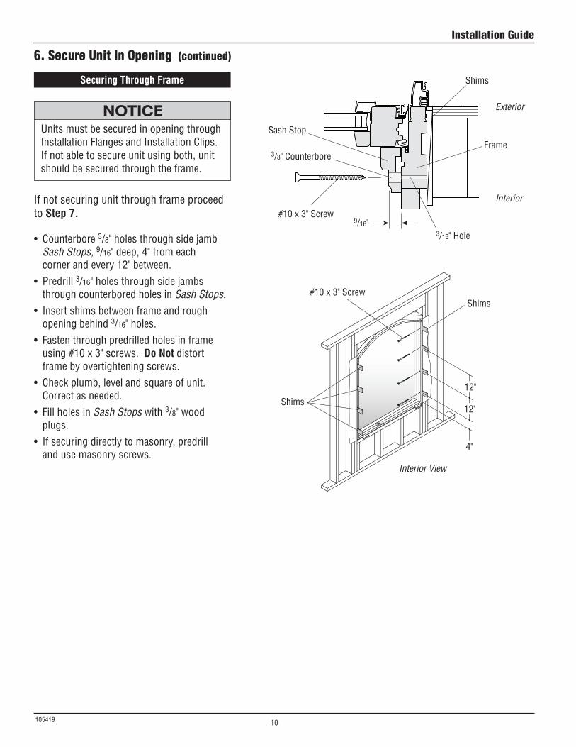
6. Secure Unit In Opening (continued)
Units must be secured in opening through Installation Flanges and Installation Clips. If not able to secure unit using both, unit should be secured through the frame.
Securing Through Frame
• Counterbore3/8" holes through side jamb Sash Stops, 9/16" deep, 4" from each corner and every 12" between.
• Predrill3/16" holes through side jambs through counterbored holes in Sash Stops.
• Insertshimsbetweenframeandroughopening behind 3/16" holes.
• Fastenthroughpredrilledholesinframeusing #10 x 3" screws. Do Not distort frame by overtightening screws.
• Checkplumb,levelandsquareofunit.Correct as needed.
• FillholesinSash Stops with 3/8" wood plugs.
• Ifsecuringdirectlytomasonry,predrilland use masonry screws.
If not securing unit through frame proceed to Step 7.
Exterior
Interior
Sash Stop
#10 x 3" Screw
Shims
Frame3/8" Counterbore
9/16" 3/16"Hole
#10 x 3" Screw
Interior View
Shims
Shims
12"
12"
4"
Installation Guide
10
105419
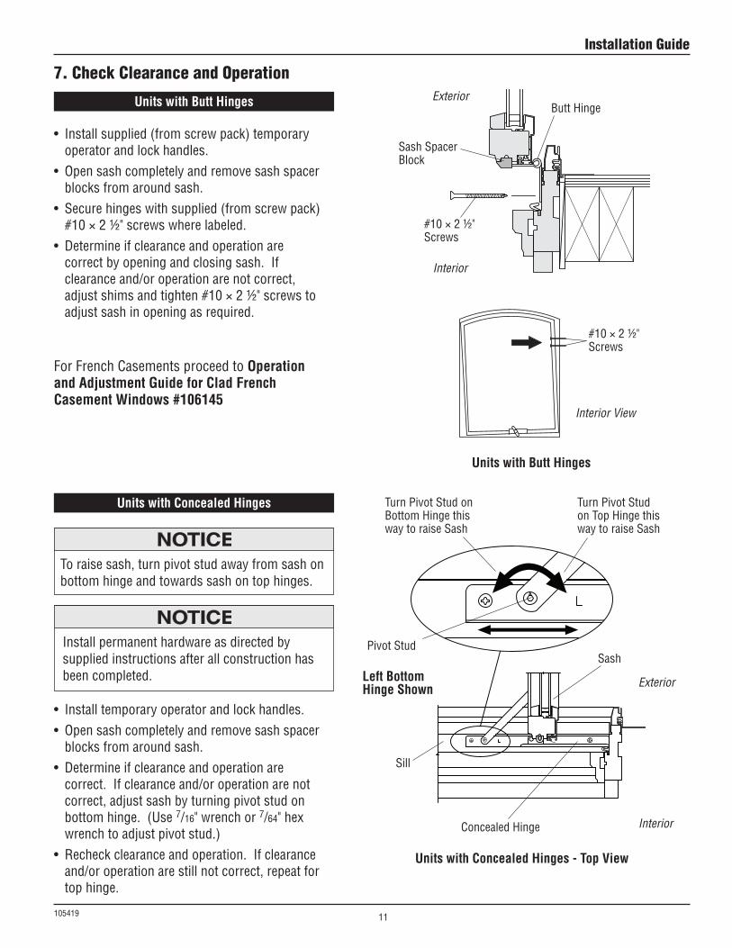
7. Check Clearance and OperationExterior
Interior
Units with Butt Hinges
Units with Concealed Hinges
• Installsupplied(fromscrewpack)temporaryoperator and lock handles.
• Opensashcompletelyandremovesashspacerblocks from around sash.
• Securehingeswithsupplied(fromscrewpack)#10 × 2 ½" screws where labeled.
• Determineifclearanceandoperationarecorrect by opening and closing sash. If clearance and/or operation are not correct, adjust shims and tighten #10 × 2 ½" screws to adjust sash in opening as required.
Interior View
ButtHinge
#10 × 2 ½" Screws
#10 × 2 ½" Screws
Sash Spacer Block
Units with Butt Hinges
Units with Concealed Hinges - Top View
Left Bottom Hinge Shown
• Installtemporaryoperatorandlockhandles.• Opensashcompletelyandremovesashspacer
blocks from around sash.• Determineifclearanceandoperationare
correct. If clearance and/or operation are not correct, adjust sash by turning pivot stud on bottom hinge. (Use 7/16" wrench or 7/64" hex wrench to adjust pivot stud.)
• Recheckclearanceandoperation.Ifclearanceand/or operation are still not correct, repeat for top hinge.
Exterior
Interior
Pivot Stud
Turn Pivot Stud on BottomHingethisway to raise Sash
Turn Pivot Stud onTopHingethisway to raise Sash
ConcealedHinge
Sash
Sill
Install permanent hardware as directed by supplied instructions after all construction has been completed.
To raise sash, turn pivot stud away from sash on bottom hinge and towards sash on top hinges.
For French Casements proceed to Operation and Adjustment Guide for Clad French Casement Windows #106145
Installation Guide
11
105419
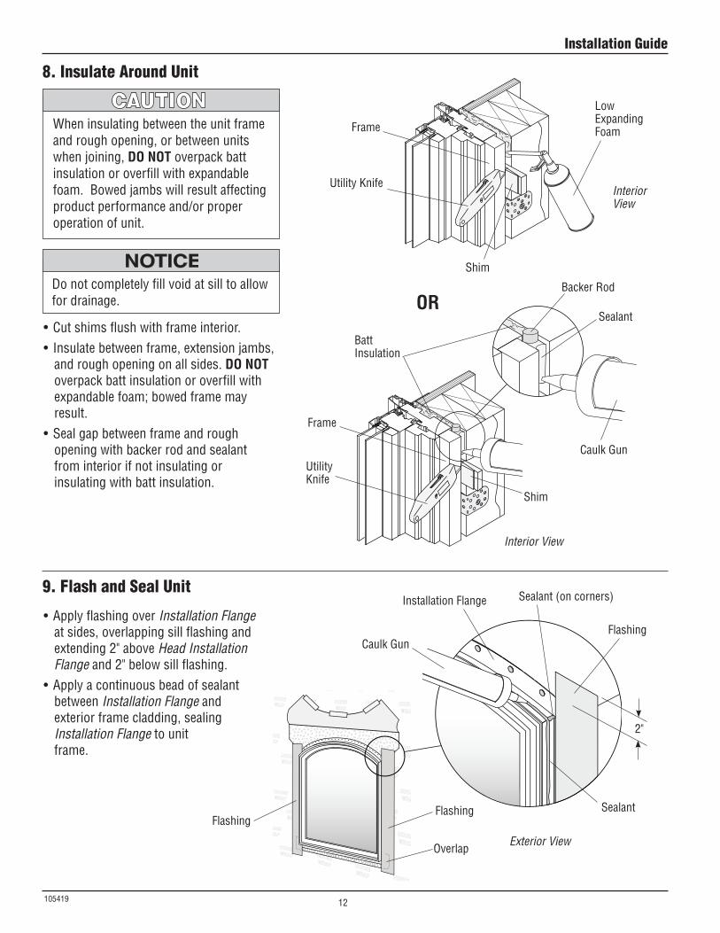
8. Insulate Around Unit
9. Flash and Seal Unit
When insulating between the unit frame and rough opening, or between units when joining, DO NOT overpack batt insulation or overfill with expandable foam.Bowedjambswillresultaffectingproduct performance and/or proper operation of unit.
Caulk Gun
BackerRod
Sealant
Shim
Shim
BattInsulation
UtilityKnife
Utility Knife
Frame
Frame
LowExpanding Foam
Interior View
Interior View
•Cutshimsflushwithframeinterior.• Insulatebetweenframe,extensionjambs,
and rough opening on all sides. DO NOT overpack batt insulation or overfill with expandable foam; bowed frame may result.
•Sealgapbetweenframeandroughopening with backer rod and sealant from interior if not insulating or insulating with batt insulation.
Donotcompletelyfillvoidatsilltoallowfor drainage.
Exterior View
•ApplyflashingoverInstallation Flange at sides, overlapping sill flashing and extending 2" above Head Installation Flange and 2" below sill flashing.
•Applyacontinuousbeadofsealantbetween Installation Flange and exterior frame cladding, sealing Installation Flange to unit frame.
Installation Flange
Caulk Gun
Sealant (on corners)
Sealant
Flashing
FlashingFlashing
Overlap
2"
OR
Installation Guide
12
105419
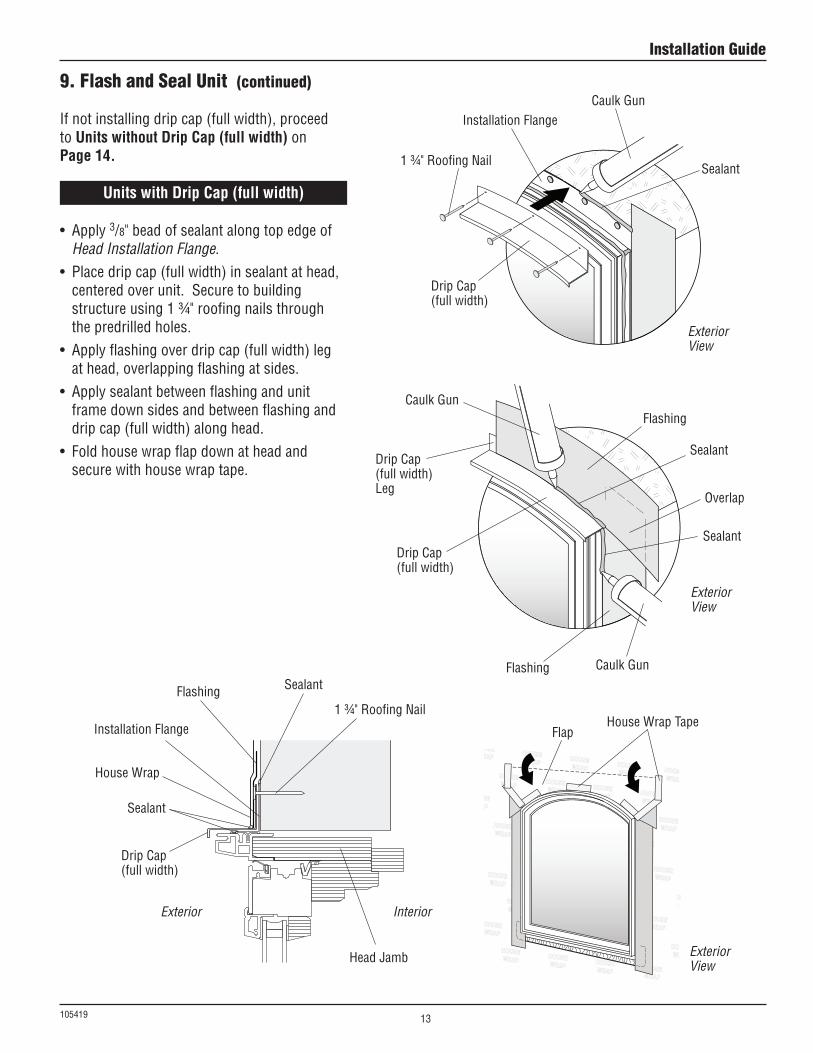
9. Flash and Seal Unit (continued)
Exterior View
FlapHouseWrapTape
Exterior View
Exterior View
Exterior Interior
• Apply3/8" bead of sealant along top edge of Head Installation Flange.
• Placedripcap(fullwidth)insealantathead,centered over unit. Secure to building structure using 1 ¾" roofing nails through the predrilled holes.
• Applyflashingoverdripcap(fullwidth)legat head, overlapping flashing at sides.
• Applysealantbetweenflashingandunitframe down sides and between flashing and drip cap (full width) along head.
• Foldhousewrapflapdownatheadandsecure with house wrap tape.
Installation Flange
Installation Flange
1 ¾" Roofing Nail
1 ¾" Roofing Nail
Caulk Gun
Caulk Gun
Caulk Gun
Sealant
Sealant
Sealant
Sealant
Sealant
Flashing
Overlap
Flashing
HeadJamb
Flashing
HouseWrap
DripCap(full width)
DripCap(full width)
DripCap(full width) Leg
DripCap(full width)
Units with Drip Cap (full width)
If not installing drip cap (full width), proceed to Units without Drip Cap (full width) on Page 14.
Installation Guide
13
105419
9. Flash and Seal Unit (continued)
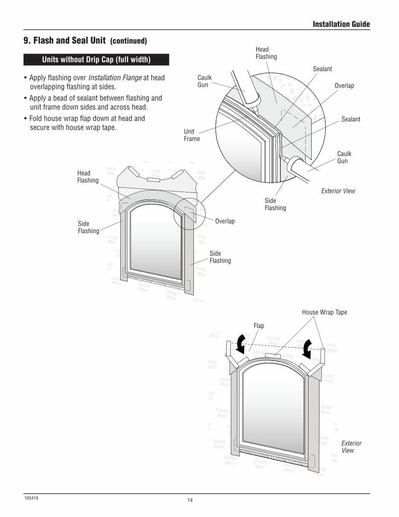
Units without Drip Cap (full width)
Exterior View
Flap
HouseWrapTape
•ApplyflashingoverInstallation Flange at head overlapping flashing at sides.
•Applyabeadofsealantbetweenflashingandunit frame down sides and across head.
• Foldhousewrapflapdownatheadandsecure with house wrap tape.
Exterior View
Caulk Gun
Unit Frame
Caulk Gun
Sealant
Sealant
Side Flashing
HeadFlashing
Side Flashing
HeadFlashing
Side Flashing
Overlap
Overlap
Installation Guide
14
105419
Exterior View
¼"Space
½" Space
Caulk Gun
½"
Exterior Finish(Brick)
Sill Plate
Exterior
Interior
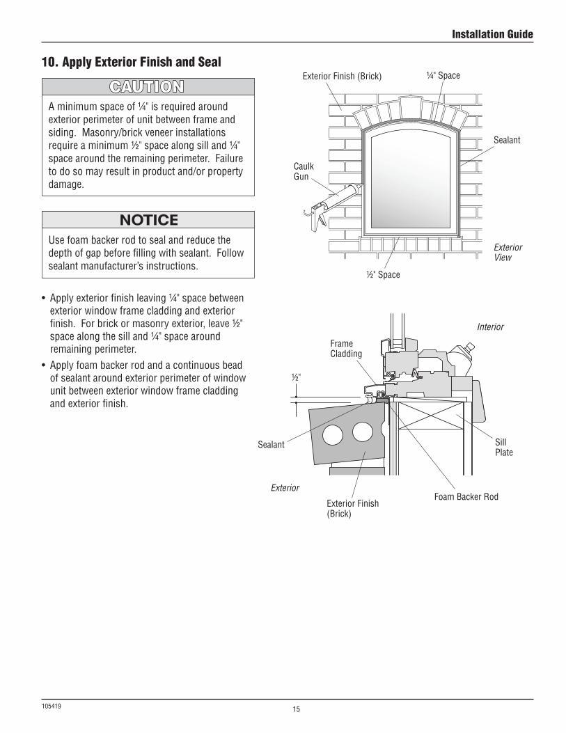
10. Apply Exterior Finish and Seal
• Applyexteriorfinishleaving¼"spacebetweenexterior window frame cladding and exterior finish. For brick or masonry exterior, leave ½" spacealongthesilland¼"spacearoundremaining perimeter.
• Applyfoambackerrodandacontinuousbeadof sealant around exterior perimeter of window unit between exterior window frame cladding and exterior finish.
Use foam backer rod to seal and reduce the depth of gap before filling with sealant. Follow sealant manufacturer’s instructions.
Aminimumspaceof¼"isrequiredaroundexterior perimeter of unit between frame and siding. Masonry/brick veneer installations requireaminimum½"spacealongsilland¼"space around the remaining perimeter. Failure to do so may result in product and/or property damage.
FoamBackerRod
Frame Cladding
Sealant
Sealant
ExteriorFinish(Brick)
Installation Guide
15

105419
This page has been intentionally left blank.
Installation Guide
16