Embed Size (px)
Citation preview
InstallationGuide
Installation instructions for EB+ Generation 2
000 700 340 rev.09 ‘08
38891 338891 3 3/10/08 15:40:263/10/08 15:40:26
Table of Contents
Page
General component guide 5
Chassis components 6
Assembly - EB+ 7
Installation options - Semi and Centre axle trailer - 8Side by Side
Installation options - Semi and Centre axle trailer - 9Side by side (SxS) 2S/2M + SL valve - Self-steered axle
Installation options - Semi and Centre axle trailer - 10Integrated Axle by Axle, ASC Front, SL Rear
Installation options - Semi and Centre axle trailer - 11Integrated Axle by Axle, ASC Rear, SL Front
Installation options - Full trailers 12
Chassis installation - Position of EB+ assembly 13
Chassis installation - Position of EB+ assembly 14
Chassis installation - Electrical wiring 15POWER/DIAG connection
Chassis installation - Electrical wiring - 16POWER ‘A’ (ISO 7638)
Chassis installation - Electrical wiring - 17POWER ‘B’ (ISO 1185, 24N)
Chassis installation - Electrical wiring - 18Diagnostic ‘DIAG’ connection
Chassis installation - Connectors/blanking plugs 19
Chassis installation - Sensor/Auxilliary Plugs 20
Chassis installation - SENSOR/AUX/DIAG Connection 21
Chassis installation - Sensor Connection 22
Chassis installation - COLAS® / ILAS®-E connection 23
Chassis installation - Painting - Masked areas 24
Chassis installation - ISO 7638 - 7 Pin 25Socket Assembly - 24V
General Chassis installation - Anti-vibration support 26
General Chassis installation - Junction box 27
General Chassis installation - Electrical wiring - 28DIAG Side of Vehicle connection
Pipe recommendations - 3 axle Semi-Trailer - 292 line air brake system - S/D brake chambers
Brake and Suspension piping layout - 3 axle 30Semi-Trailer - 2 line air brake system - with R.E.V -S/D brake chambers
Brake piping layout - 2M - 3 axle Semi-Trailer - 2 line 31air brake system - without R.E.V. - Spring brake chambers
Brake piping layout - 2M - Side by Side 3 axle with TrCM 32and Spring Brake chambers
Brake piping layout - Axle by Axle - 3 axle Semi-Trailer 33with R.E.V. & Combined Park and Shunt valve
Page
Brake piping layout - Side by Side 3 axle with R.E.V. & 34Combined Park and Shunt valve
Suspension system piping layout - Levelling valve 35
Suspension system piping layout - Levelling valve, 36Colas® (auto reset to ride)
Suspension system piping layout - 3 axle 37Semi-Trailer, Levelling valve, Colas® with auto reset to ride & ILAS®-E
Suspension system piping layout - Option 1 - 383 axle Semi-Trailer, Colas® with height limitation and auto reset to ride
Suspension system piping layout - Option 2 - 393 axle Semi-Trailer, Colas® with height limitation and auto reset to ride
Suspension system piping layout - 3 axle Semi-Trailer, 402 line air brake, spring brake chambers with combined park & shunt valve
Suspension system piping layout - 2 axle Full Trailer, 412 line air brake, spring brake chambers
Wiring schematic 42
Wiring diagram - 2 Sensor, ISO 7638 & ISO 1185 with 43Info Centre (3 AUXs fi tted)
Auxilliary equipment wiring - 2 Sensor, ISO 7638 & 44ISO 1185 with Info Centre and L.W.S. (3 AUXs fi tted)
Auxilliary equipment wiring - COLAS®/ ILAS®, 45Steer Axle Lock
Auxilliary equipment wiring - Traction assist 46
Wiring Diagram - Full system information 47
Hazardous Goods/ADR Installations 48
Hazardous Goods/ADR Installations 49
Programming 50
Multimeter readings 51
38891 H:238891 H:2 3/10/08 15:40:333/10/08 15:40:33
Notes on the use of this manualDocument Registration
Preceding the Haldex EB+ main index sheet, this manual should contain the document registration form and an amendment record sheet. Both of these documents are intended to assist your Company and Haldex Brake Products Ltd in maintaining this manual in an up to date condition.
Please follow the instructions included on each sheet to ensure that we are able to give both yourself and your company the best product information support whenever the need may arise.
This manual has been designed to assist personnel in satisfactorily installing Haldex EB+on Semi and Centre axle trailers.
The intention has been to illustrate the various areas of installation. It is expected that this manual will be in possession of the appropriate person throughout their ‘training’ and ‘experience’ and that the manual will be used as:
a) A teaching aid following supervision of a HALDEX ENGINEER.
b) A reminder of the correct procedure of Haldex EB+ installation.
For any other deviation consult Haldex Brake Products Ltd. Moons Moat Drive, Moons Moat North, Redditch, Worcestershire B98 9HA Tel: +44 1527 499 499 Fax: +44 1527 499 500.
• Use appropriate spare-parts documentation when obtaining spare parts.
• Use only genuine Haldex parts in repairs.
• Due to continuous development the right is reserved to alter the specifi cation without notice
• No legal rights can be derived from the contents of the manual.
• Duplication, translation and reprinting are prohibited without permission from Haldex Brake Systems.
Document Registration
Included below is a postcard which enables you to register ownership of the this Installation Guide document.
Please fi ll in the details requested, including your postcode , in block capitals using a non eraseable ink and return the card to us. This will enable us to ensure that any necessary installation instructions revisions which are issued by Haldex Brake Products Ltd will be forwarded to you automatically.
If you do not return the information to us we regret that we will be unable to ensure that your installation instruction is kept up to date.
If you should have any queries regarding this document or its contents please contact your local Technical Services Offi ce.
EB+ Installation Instructions Registration - Please fi ll in your details below.
YOUR NAME
COMPANY
DELIVERY ADDRESS
POST CODE
38891 H:338891 H:3 3/10/08 15:40:343/10/08 15:40:34
EB+ Installation Instructions Registration
PleaseAffi x
StampHere
Document Registration
MARKETING DEPT.
HALDEX BRAKE PRODUCTS LTD
MOONS MOAT DRIVE
REDDITCH
B98 9HA
UNITED KINGDOM
38891 H:438891 H:4 3/10/08 15:40:343/10/08 15:40:34
5
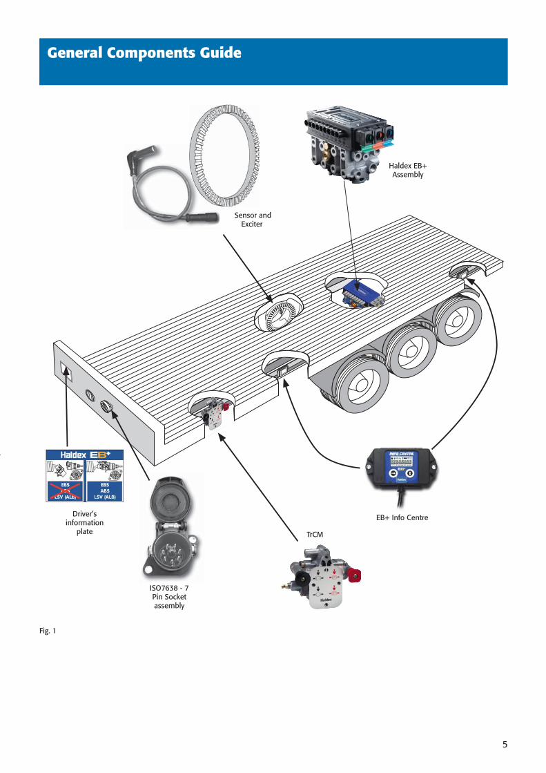
General Components Guide
Driver’s information
plate
Haldex EB+ Assembly
EB+ Info Centre
ISO7638 - 7 Pin Socket assembly
Sensor and Exciter
TrCM
Fig. 1
38891 H:538891 H:5 3/10/08 15:40:343/10/08 15:40:34
6
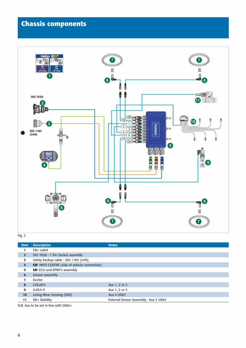
Chassis components
Item Description Notes1 EB+ Label2 ISO 7638 - 7 Pin Socket assembly3 Safety backup cable - ISO 1185 (24N)4 EB+ INFO CENTRE (side of vehicle connection) 5 EB+ ECU and EPRV’s assembly6 Sensor assembly7 Exciter8 COLAS® Aux 1, 2 or 39 ILAS®-E Aux 1, 2 or 310 Lining Wear Sensing (LWS) Aux 4 ONLY11 EB+ Stability External Sensor Assembly - Aux 5 ONLY
Fig. 2
2A1A
54
32
11B
2B
6
7
6
7
6
7
6
7
11
10
9
8
4
3
2
1
5
ISO 7638
ISO 1185(24N)
N.B. Aux to be set in line with DIAG+
38891 H:638891 H:6 3/10/08 15:40:423/10/08 15:40:42
7
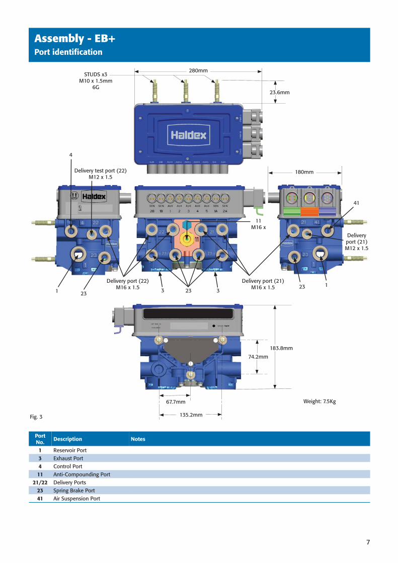
STUDS x3M10 x 1.5mm
6G
Weight: 7.5Kg
Fig. 3
Delivery port (21) M16 x 1.5
Delivery port (22)M16 x 1.5
280mm
180mm
23.6mm
67.7mm
135.2mm
74.2mm
183.8mm
Assembly - EB+Port identifi cation
Port No. Description Notes
1 Reservoir Port3 Exhaust Port4 Control Port 11 Anti-Compounding Port
21/22 Delivery Ports23 Spring Brake Port41 Air Suspension Port
4
1 23 2323 1
41
33
11M16 x
Delivery test port (22)M12 x 1.5
Delivery port (21)M12 x 1.5
38891 H:738891 H:7 3/10/08 15:40:463/10/08 15:40:46
8
S1B
S1A
S1B
S1A
S1B
S1A
S1B
S1A
S1B
S1A
S1B
S1A
S1B
S1A
S1B
S1A
S1B
S1A
2221
S2B
S2A
2122
2221
2221
S1B
S1A
2221
2122
2122
2122
S1B
S1A
2221
S1B
S1A
S2B
S2A
2122
2122
S2B
S2A
S2B
S2A
2221
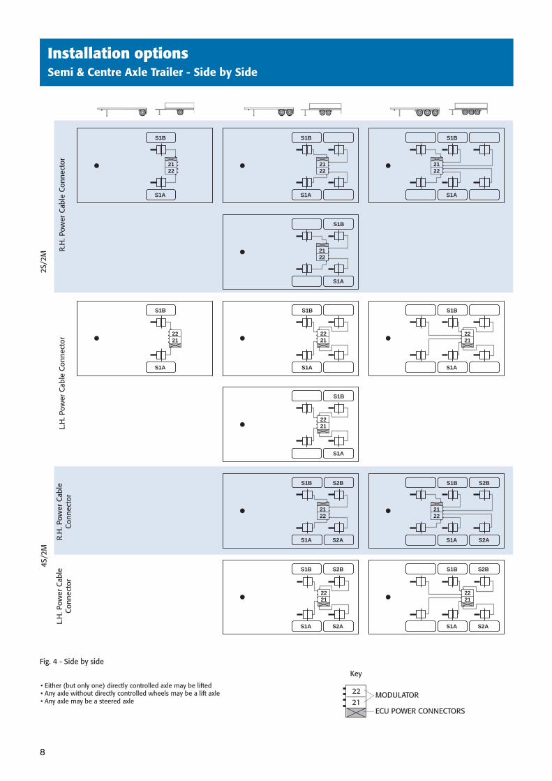
Installation options Semi & Centre Axle Trailer - Side by Side
Fig. 4 - Side by side
• Either (but only one) directly controlled axle may be lifted• Any axle without directly controlled wheels may be a lift axle• Any axle may be a steered axle
MODULATOR
ECU POWER CONNECTORS
Key
R.H
. Pow
er C
able
Con
nect
orL.
H. P
ower
Cab
le C
onne
ctor
R.H
. Pow
er C
able
Con
nect
or
L.H
. Pow
er C
able
C
onne
ctor
4S/2
M
2
S/2M
2221
38891 H:838891 H:8 3/10/08 15:40:493/10/08 15:40:49
9
2S/
2M
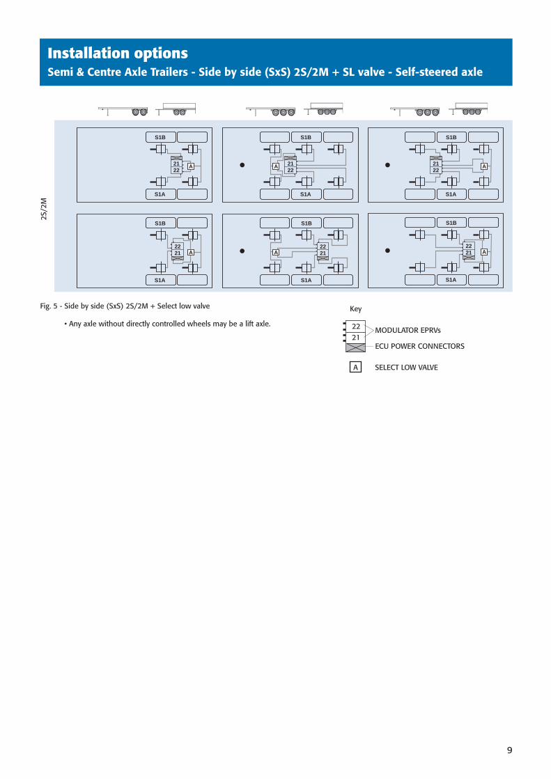
Fig. 5 - Side by side (SxS) 2S/2M + Select low valve
• Any axle without directly controlled wheels may be a lift axle.MODULATOR EPRVs
ECU POWER CONNECTORS
Key
2221
Installation optionsSemi & Centre Axle Trailers - Side by side (SxS) 2S/2M + SL valve - Self-steered axle
S1B
S1A
S1B
S1A
2221
2122
S1B
S1A
2122
A A A
S1B
S1A
2221 A
S1B
S1A
2221 A A
S1B
S1A
2122
A SELECT LOW VALVE
38891 H:938891 H:9 3/10/08 15:40:503/10/08 15:40:50
10
S1B
S1A
S2B
S2A
S1B
S1A
S2B
S2A
S1B
S1A
2221
2221
2122
S2B
S2A
N1
N2
S1B
S1A
S2B
S2A
2122
N1
N4
N1
N4
N3
N2
S1B
S1A
S2B
S2A
2221
N3
N2
S1B
S1A
2122
S2B
S2A
N1
N4
4S/2
M
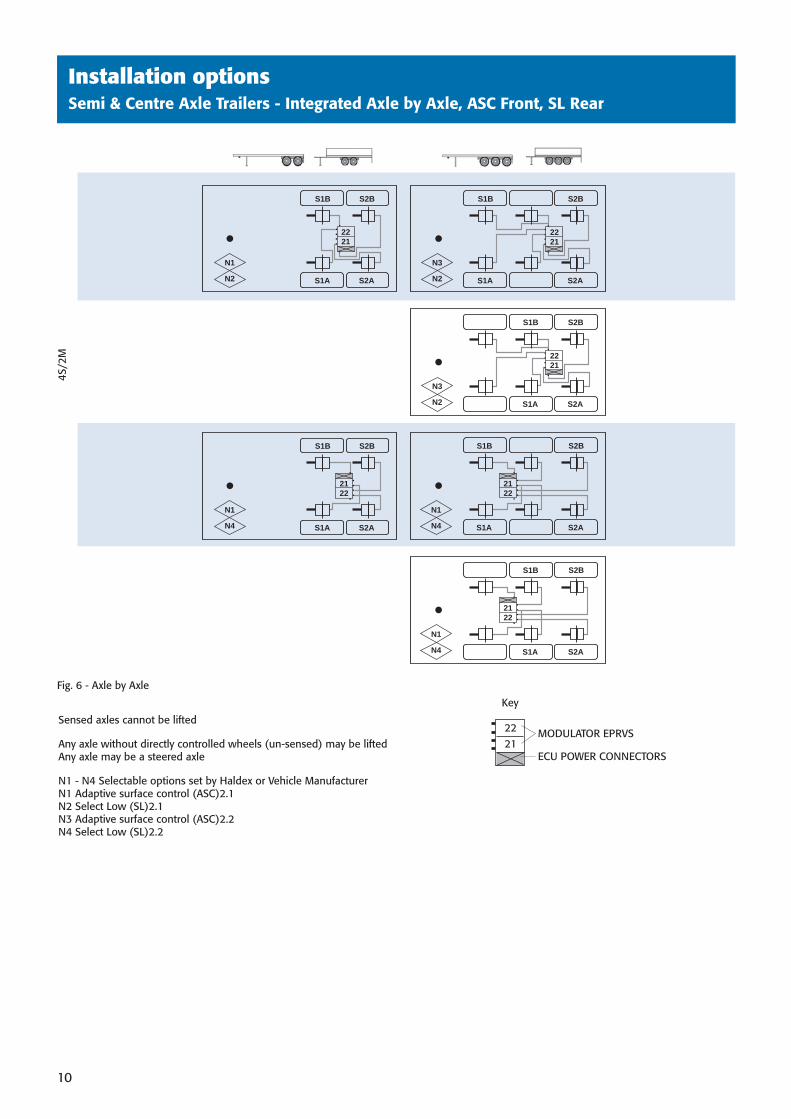
Sensed axles cannot be lifted
Any axle without directly controlled wheels (un-sensed) may be liftedAny axle may be a steered axle
N1 - N4 Selectable options set by Haldex or Vehicle ManufacturerN1 Adaptive surface control (ASC)2.1N2 Select Low (SL)2.1N3 Adaptive surface control (ASC)2.2N4 Select Low (SL)2.2
Fig. 6 - Axle by Axle
MODULATOR EPRVS
ECU POWER CONNECTORS
Key
2221
Installation optionsSemi & Centre Axle Trailers - Integrated Axle by Axle, ASC Front, SL Rear
38891 H:1038891 H:10 3/10/08 15:40:503/10/08 15:40:50
11
S1B
S1A
S2B
S2A
S1B
S1A
S2B
S2A
S1B
S1A
2221
2221
2122
S2B
S2A
N4
N1
S1B
S1A
S2B
S2A
2122
N2
N3
N1
N4
N1
N4
S1B
S1A
S2B
S2A
2221
N1
N4
S1B
S1A
2122
S2B
S2A
N2
N3
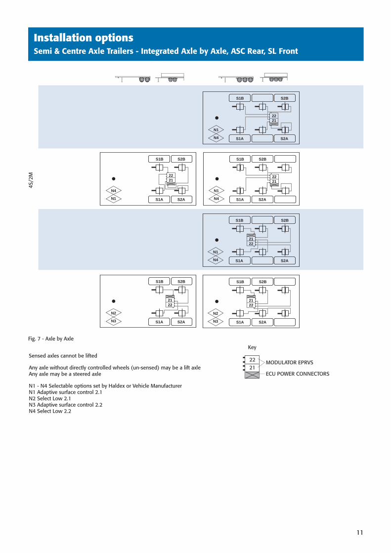
Installation optionsSemi & Centre Axle Trailers - Integrated Axle by Axle, ASC Rear, SL Front
4S/2
M
Sensed axles cannot be lifted
Any axle without directly controlled wheels (un-sensed) may be a lift axleAny axle may be a steered axle
N1 - N4 Selectable options set by Haldex or Vehicle ManufacturerN1 Adaptive surface control 2.1N2 Select Low 2.1N3 Adaptive surface control 2.2N4 Select Low 2.2
Fig. 7 - Axle by Axle
MODULATOR EPRVS
ECU POWER CONNECTORS
Key
2221
38891 H:1138891 H:11 3/10/08 15:40:513/10/08 15:40:51
12
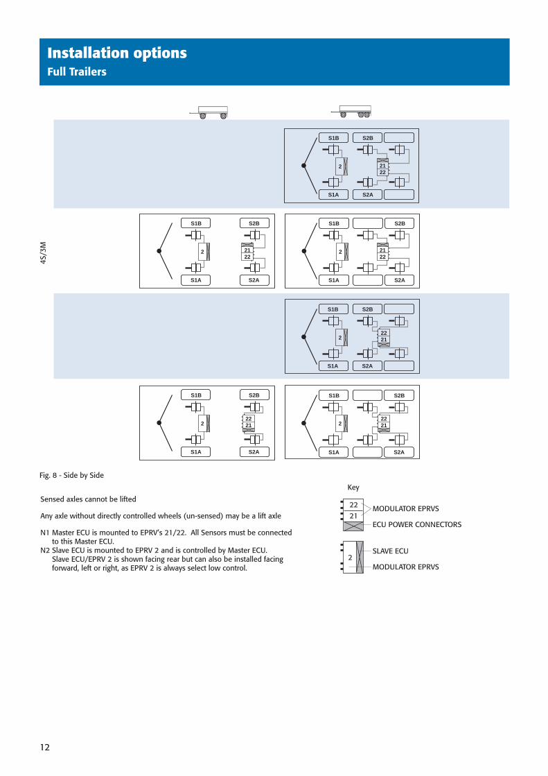
Installation optionsFull Trailers
4S/3
M
Sensed axles cannot be lifted
Any axle without directly controlled wheels (un-sensed) may be a lift axle
N1 Master ECU is mounted to EPRV’s 21/22. All Sensors must be connected to this Master ECU.
N2 Slave ECU is mounted to EPRV 2 and is controlled by Master ECU.Slave ECU/EPRV 2 is shown facing rear but can also be installed facing forward, left or right, as EPRV 2 is always select low control.
Fig. 8 - Side by Side
MODULATOR EPRVS
SLAVE ECU
ECU POWER CONNECTORS
MODULATOR EPRVS
Key
2221
2
2
S1B
S1A
S2B
S2A
2
S1B
S1A
S2B
S2A
2
S1B
S1A
S2B
S2A
S1B
S1A
S2B
S2A
S2B
S2A
2
S1B
S1A
S2B
S2A
2
S1B
S1A
2122
2122
2122
2221
2221
2221
2
38891 H:1238891 H:12 3/10/08 15:40:513/10/08 15:40:51
Chassis installationPosition of EB+ assembly
13
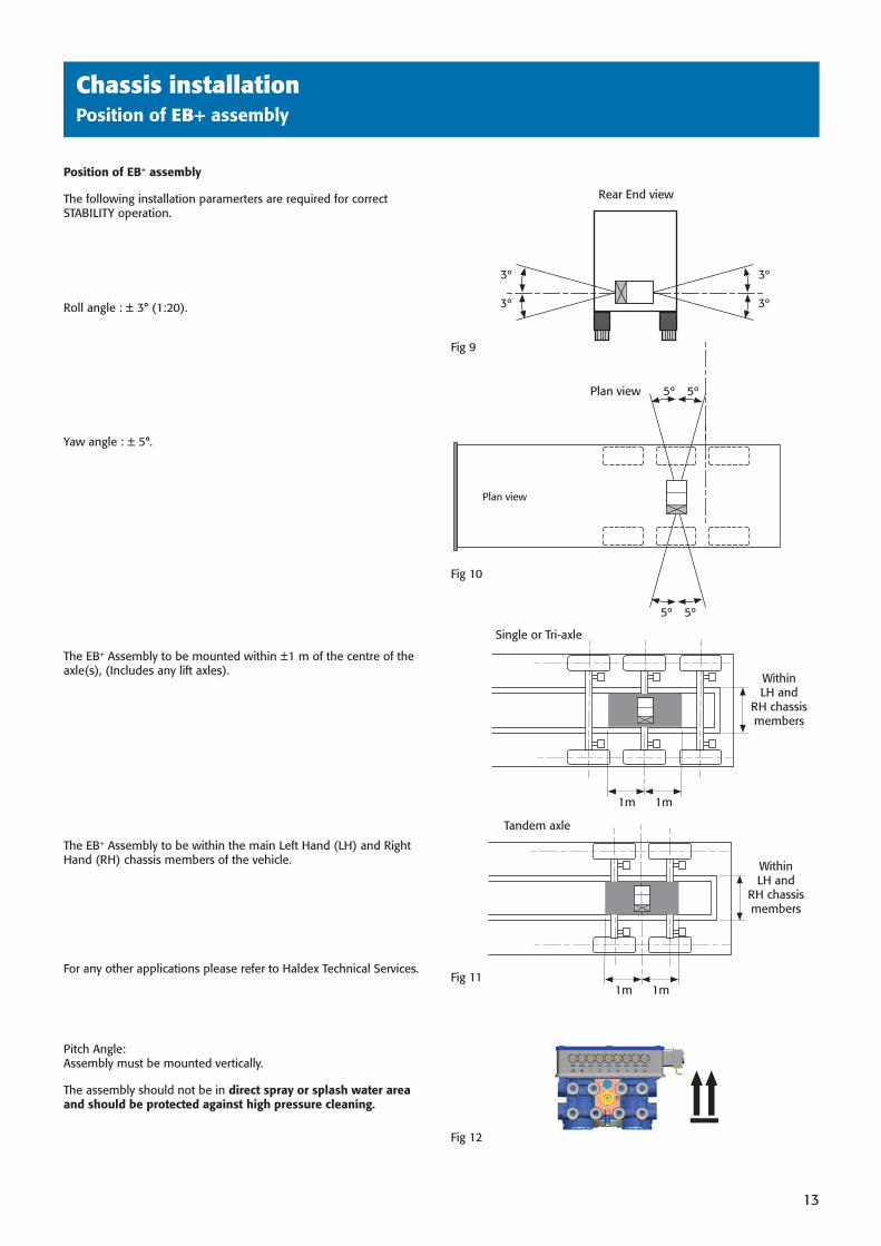
Position of EB+ assembly
The following installation paramerters are required for correct STABILITY operation.
Roll angle : ± 3° (1:20).
Yaw angle : ± 5°.
The EB+ Assembly to be mounted within ±1 m of the centre of the axle(s), (Includes any lift axles).
The EB+ Assembly to be within the main Left Hand (LH) and Right Hand (RH) chassis members of the vehicle.
For any other applications please refer to Haldex Technical Services.
Pitch Angle: Assembly must be mounted vertically.
The assembly should not be in direct spray or splash water area and should be protected against high pressure cleaning.
Fig 9
Fig 12
1m 1m
Within LH and
RH chassis members
Single or Tri-axle
5º5º
5º5º
Plan view
Plan view
Fig 10
3º
3º
3º
3º
Rear End view
1m 1m
Within LH and
RH chassis members
Fig 11
Tandem axle
38891 H:1338891 H:13 3/10/08 15:40:523/10/08 15:40:52
Chassis installationPosition of EB+ assembly
14
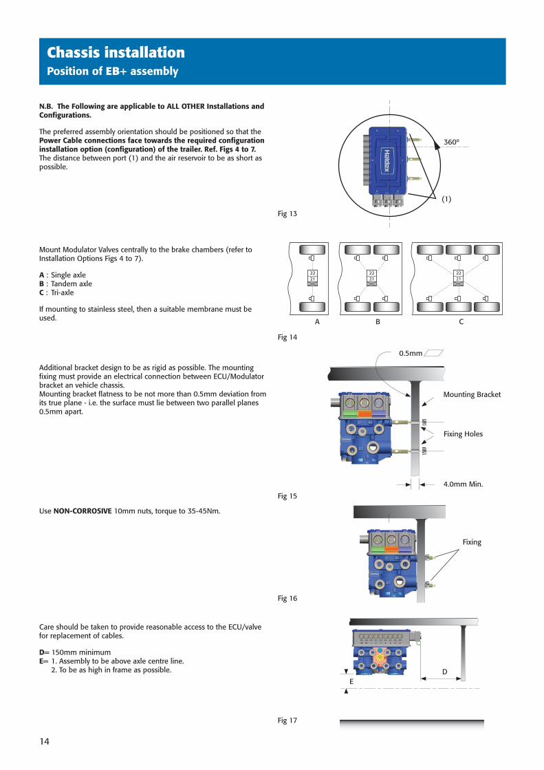
N.B. The Following are applicable to ALL OTHER Installations and Confi gurations.
The preferred assembly orientation should be positioned so that the Power Cable connections face towards the required confi guration installation option (confi guration) of the trailer. Ref. Figs 4 to 7.The distance between port (1) and the air reservoir to be as short as possible.
Mount Modulator Valves centrally to the brake chambers (refer to Installation Options Figs 4 to 7).
A : Single axleB : Tandem axleC : Tri-axle
If mounting to stainless steel, then a suitable membrane must be used.
Additional bracket design to be as rigid as possible. The mounting fi xing must provide an electrical connection between ECU/Modulator bracket an vehicle chassis.Mounting bracket fl atness to be not more than 0.5mm deviation from its true plane - i.e. the surface must lie between two parallel planes 0.5mm apart.
Use NON-CORROSIVE 10mm nuts, torque to 35-45Nm.
Care should be taken to provide reasonable access to the ECU/valve for replacement of cables.
D= 150mm minimumE= 1. Assembly to be above axle centre line. 2. To be as high in frame as possible.
A B C
Fig 14
Fig 17
Fig 15
Fig 16
Fig 13
Fixing
2221
2221
2221
(1)
360º
0.5mm
4.0mm Min.
Mounting Bracket
Fixing Holes
ED
38891 H:1438891 H:14 3/10/08 15:40:533/10/08 15:40:53
Chassis installation
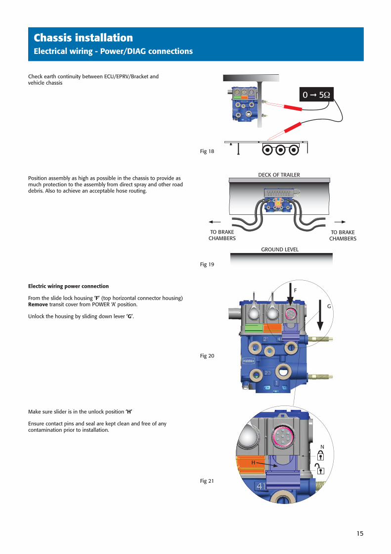
Check earth continuity between ECU/EPRV/Bracket and vehicle chassis
Position assembly as high as possible in the chassis to provide as much protection to the assembly from direct spray and other road debris. Also to achieve an acceptable hose routing.
Electric wiring power connection
From the slide lock housing ‘F’ (top horizontal connector housing) Remove transit cover from POWER ‘A’ position.
Unlock the housing by sliding down lever ‘G’.
Make sure slider is in the unlock position ‘H’
Ensure contact pins and seal are kept clean and free of any contamination prior to installation.
Fig 19
Fig 21
Fig 18
0 5
GROUND LEVEL
TO BRAKECHAMBERS
DECK OF TRAILER
TO BRAKECHAMBERS
Fig 20
F
G
N
Chassis installationElectrical wiring - Power/DIAG connections
15
H
38891 H:1538891 H:15 3/10/08 15:40:553/10/08 15:40:55
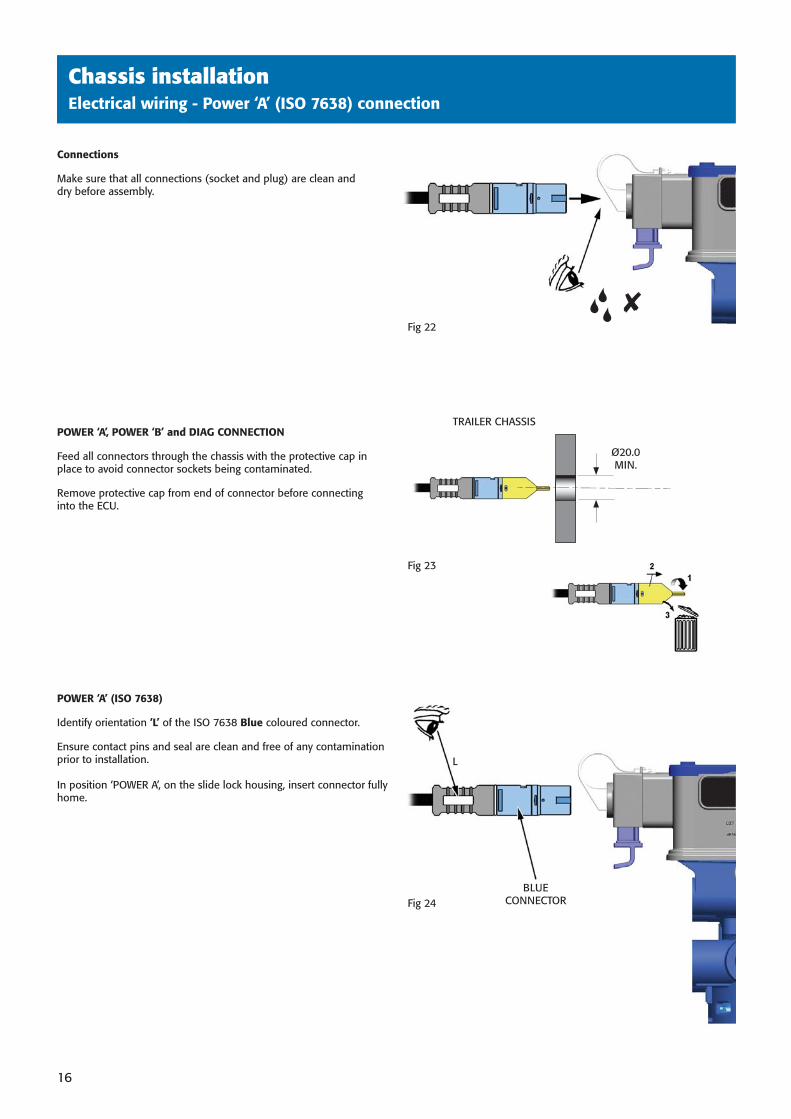
Connections
Make sure that all connections (socket and plug) are clean and dry before assembly.
POWER ‘A’, POWER ‘B’ and DIAG CONNECTION
Feed all connectors through the chassis with the protective cap in place to avoid connector sockets being contaminated.
Remove protective cap from end of connector before connecting into the ECU.
POWER ‘A’ (ISO 7638)
Identify orientation ‘L’ of the ISO 7638 Blue coloured connector.
Ensure contact pins and seal are clean and free of any contamination prior to installation.
In position ‘POWER A’, on the slide lock housing, insert connector fully home.
Chassis installation
Fig 23
TRAILER CHASSIS
Ø20.0MIN.
L
✘
BLUECONNECTOR
Chassis installationElectrical wiring - Power ‘A’ (ISO 7638) connection
16
Fig 22
Fig 24
38891 H:1638891 H:16 3/10/08 15:41:013/10/08 15:41:01
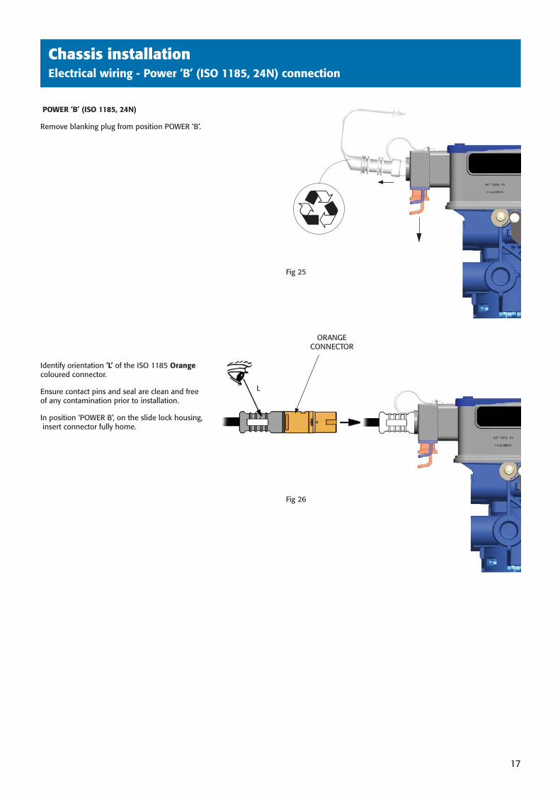
ORANGECONNECTOR
Chassis installationElectrical wiring - Power ‘B’ (ISO 1185, 24N) connection
17
POWER ‘B’ (ISO 1185, 24N)
Remove blanking plug from position POWER ‘B’.
Identify orientation ‘L’ of the ISO 1185 Orange coloured connector.
Ensure contact pins and seal are clean and free of any contamination prior to installation.
In position ‘POWER B’, on the slide lock housing, insert connector fully home.
Fig 26
Fig 25
L
38891 H:1738891 H:17 3/10/08 15:41:023/10/08 15:41:02
Chassis installationElectrical wiring - ‘DIAG’ connection
18
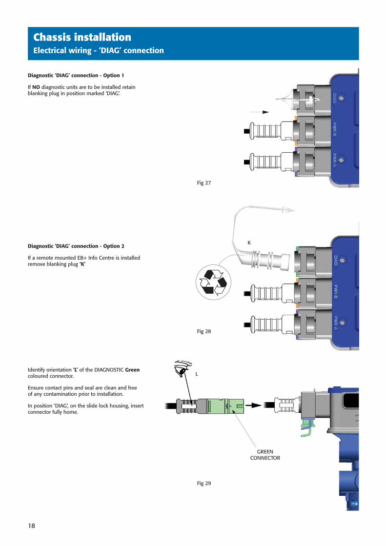
Diagnostic ‘DIAG’ connection - Option 1
If NO diagnostic units are to be installed retain blanking plug in position marked ‘DIAG’.
Diagnostic ‘DIAG’ connection - Option 2
If a remote mounted EB+ Info Centre is installed remove blanking plug ‘K’
Identify orientation ‘L’ of the DIAGNOSTIC Green coloured connector.
Ensure contact pins and seal are clean and free of any contamination prior to installation.
In position ‘DIAG’, on the slide lock housing, insert connector fully home.
K
Fig 27
Fig 28
L
GREEN CONNECTOR
Fig 29
38891 H:1838891 H:18 3/10/08 15:41:033/10/08 15:41:03
Auxiliary equipment wiringsecond title here
19
Chassis installationElectrical wiring - Connectors/blanking plugs
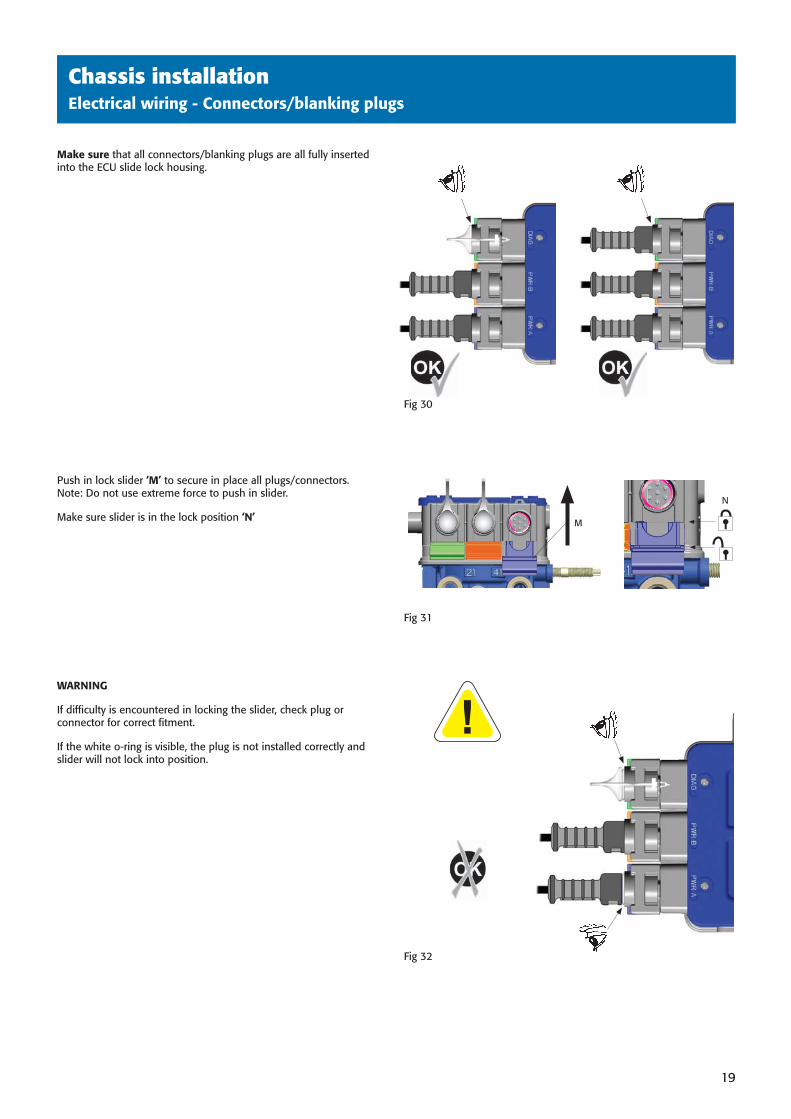
Make sure that all connectors/blanking plugs are all fully inserted into the ECU slide lock housing.
Push in lock slider ‘M’ to secure in place all plugs/connectors.Note: Do not use extreme force to push in slider.
Make sure slider is in the lock position ‘N’
WARNING
If diffi culty is encountered in locking the slider, check plug or connector for correct fi tment.
If the white o-ring is visible, the plug is not installed correctly and slider will not lock into position.
Fig 32
Fig 31
Fig 30
M
N
38891 H:1938891 H:19 3/10/08 15:41:043/10/08 15:41:04
Auxiliary equipment wiringsecond title here
20
Chassis installationElectrical wiring - SENSOR/AUX plugs
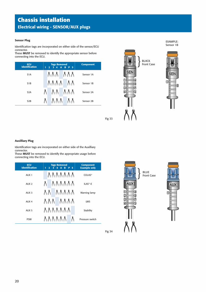
Sensor Plug
Identifi cation tags are incorporated on either side of the sensor/ECU connector.These MUST be removed to identify the appropriate sensor before connecting into the ECU.
ECUIdentifi cation
Tags Removed1 2 3 4 A B P 5
Component
S1A Sensor 1A
S1B Sensor 1B
S2A Sensor 2A
S2B Sensor 2B
Auxilliary Plug
Identifi cation tags are incorporated on either side of the Auxilliary connector.These MUST be removed to identify the appropriate usage before connecting into the ECU.
ECUIdentifi cation
Tags Removed1 2 3 4 A B P 5
ComponentExample only
AUX 1 COLAS®
AUX 2 ILAS®-E
AUX 3 Warning lamp
AUX 4 LWS
AUX 5 Stability
PSW Pressure switch
Fig 33
Fig 34
BLACKFront Case}
} BLUEFront Case
EXAMPLE:Sensor 1B
38891 H:2038891 H:20 3/10/08 15:41:093/10/08 15:41:09
Auxiliary equipment wiringsecond title here
21
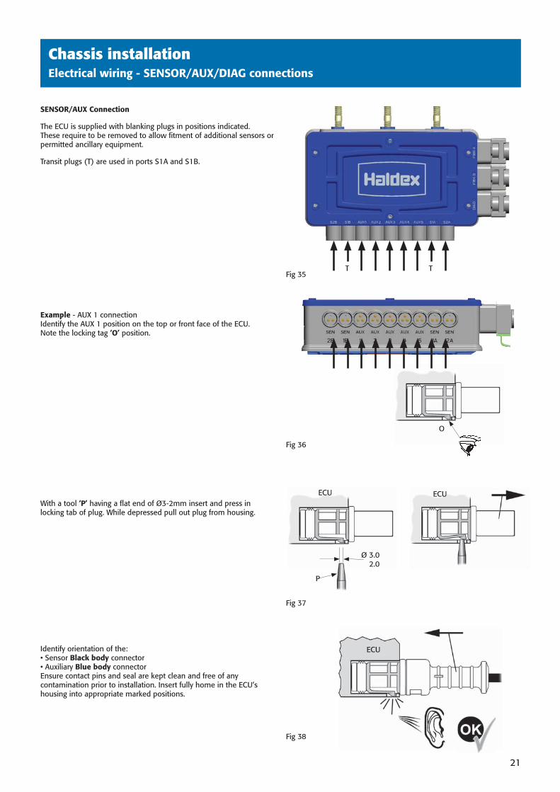
SENSOR/AUX Connection
The ECU is supplied with blanking plugs in positions indicated.These require to be removed to allow fi tment of additional sensors or permitted ancillary equipment.
Transit plugs (T) are used in ports S1A and S1B.
Example - AUX 1 connectionIdentify the AUX 1 position on the top or front face of the ECU.Note the locking tag ‘O’ position.
With a tool ‘P’ having a fl at end of Ø3-2mm insert and press in locking tab of plug. While depressed pull out plug from housing.
Identify orientation of the:• Sensor Black body connector• Auxiliary Blue body connectorEnsure contact pins and seal are kept clean and free of any contamination prior to installation. Insert fully home in the ECU’s housing into appropriate marked positions.
Fig 35
Fig 36
Fig 37
Fig 38
P
Ø 3.02.0
ECU ECU
ECU
O
Chassis installationElectrical wiring - SENSOR/AUX/DIAG connections
TT
38891 H:2138891 H:21 3/10/08 15:41:113/10/08 15:41:11
Auxiliary equipment wiringsecond title here
22
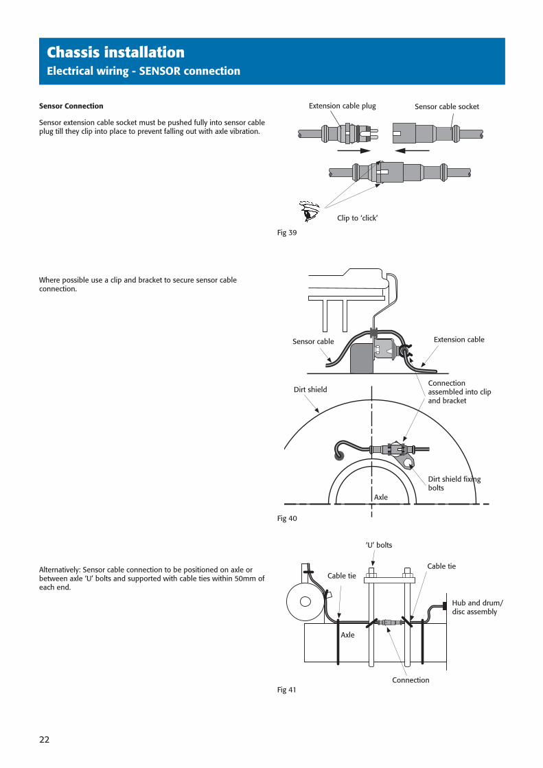
Sensor Connection
Sensor extension cable socket must be pushed fully into sensor cable plug till they clip into place to prevent falling out with axle vibration.
Where possible use a clip and bracket to secure sensor cable connection.
Alternatively: Sensor cable connection to be positioned on axle or between axle ‘U’ bolts and supported with cable ties within 50mm of each end.
Chassis installationElectrical wiring - SENSOR connection
Fig 39
Fig 41
Sensor cable socketExtension cable plug
Clip to ‘click’
Dirt shield
Sensor cable Extension cable
Dirt shield fi xing bolts
Axle
Connection assembled into clip and bracket
‘U’ bolts
Connection
Axle
Hub and drum/disc assembly
Cable tieCable tie
Fig 40
38891 H:2238891 H:22 3/10/08 15:41:133/10/08 15:41:13
Auxiliary equipment wiringsecond title here
23
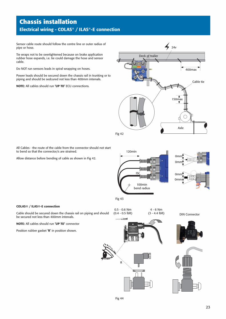
Sensor cable route should follow the centre line or outer radius of pipe or hose.
Tie wraps not to be overtightened because on brake application rubber hose expands, i.e. tie could damage the hose and sensor cable.
Do NOT run sensors leads in spiral wrapping on hoses.
Power leads should be secured down the chassis rail in trunking or to piping and should be sedcured not less than 400mm intervals.
NOTE: All cables should run ‘UP TO’ ECU connections.
All Cables - the route of the cable from the connector should not start to bend so that the connector/s are strained.
Allow distance before bending of cable as shown in Fig 42.
COLAS® / ILAS®-E connection
Cable should be secured down the chassis rail on piping and should be secured not less than 400mm intervals.
NOTE: All cables should run ‘UP TO’ connector
Position rubber gasket ‘R’ in position shown.
Chassis installationElectrical wiring - COLAS® / ILAS®-E connection
0.5 - 0.6 Nm (0.4 - 0.5 lbft)
4 - 6 Nm(3 - 4.4 lbft)
Fig 44
Fig 43
120min
ISO7638
0mm
0mm
0mm
0mm
R
24v
Cable tie
Axle
400max
Deck of trailer
Fig 42
150max
100min bend radius
DIN Connector
38891 H:2338891 H:23 3/10/08 15:41:133/10/08 15:41:13
Auxiliary equipment wiringsecond title here
24
Chassis installationPainting - masked areas
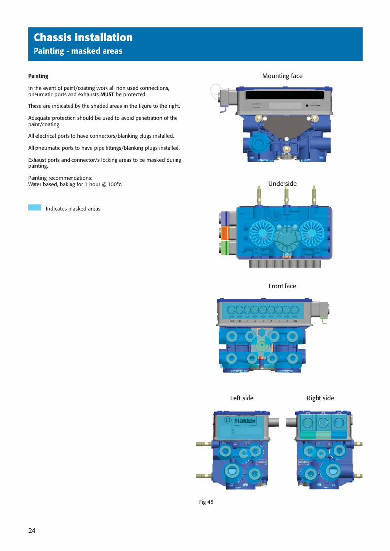
Painting
In the event of paint/coating work all non used connections, pneumatic ports and exhausts MUST be protected.
These are indicated by the shaded areas in the fi gure to the right.
Adequate protection should be used to avoid penetration of the paint/coating.
All electrical ports to have connectors/blanking plugs installed.
All pneumatic ports to have pipe fi ttings/blanking plugs installed.
Exhaust ports and connector/s locking areas to be masked during painting.
Painting recommendations: Water based, baking for 1 hour @ 100°c.
Indicates masked areas
Left side Right side
Fig 45
Underside
Mounting face
Front face
38891 H:2438891 H:24 3/10/08 15:42:273/10/08 15:42:27
Auxiliary equipment wiringsecond title here
25
Chassis installationElectrical wiring - ISO 7638 - 7 Pin Socket Assembly - 24V
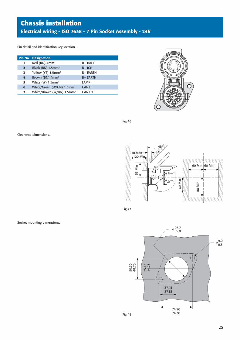
Pin detail and identifi cation key location.
Clearance dimensions.
Socket mounting dimensions.
Fig 46
Fig 47
Fig 48
Key
10 Max 120 Min
45º
60 M
ax
55 M
in 60 Min 60 Min
80 M
in
50.3
048
.70
25.1
524
.25
74.9074.30
37.4537.15
9.08.5
57.055.0ø
ø
Pin No. Designation1 Red (RD) 4mm2 B+ BATT2 Black (BK) 1.5mm2 B+ IGN3 Yellow (YE) 1.5mm2 B+ EARTH4 Brown (BN) 4mm2 B– EARTH5 White (W) 1.5mm2 LAMP6 White/Green (W/GN) 1.5mm2 CAN HI7 White/Brown (W/BN) 1.5mm2 CAN LO
213
45
67
38891 H:2538891 H:25 3/10/08 15:42:313/10/08 15:42:31
Auxiliary equipment wiringsecond title here
26
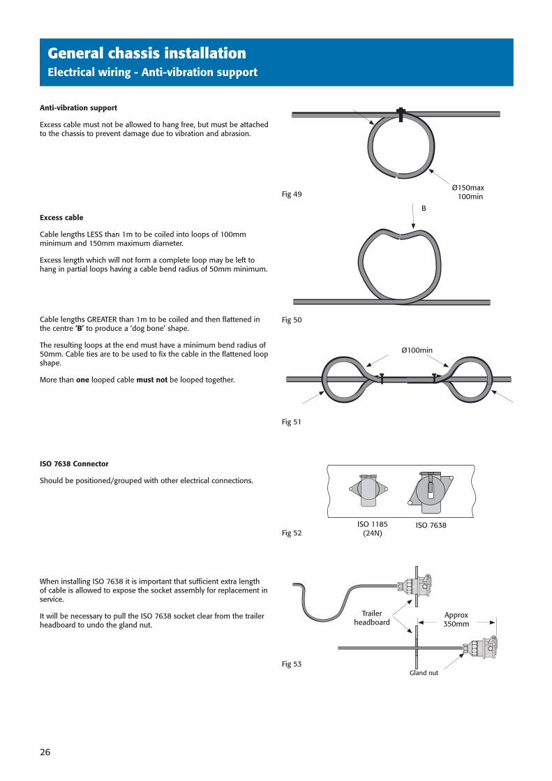
Anti-vibration support
Excess cable must not be allowed to hang free, but must be attached to the chassis to prevent damage due to vibration and abrasion.
Excess cable
Cable lengths LESS than 1m to be coiled into loops of 100mm minimum and 150mm maximum diameter.
Excess length which will not form a complete loop may be left to hang in partial loops having a cable bend radius of 50mm minimum.
Cable lengths GREATER than 1m to be coiled and then fl attened in the centre ‘B’ to produce a ‘dog bone’ shape.
The resulting loops at the end must have a minimum bend radius of 50mm. Cable ties are to be used to fi x the cable in the fl attened loop shape.
More than one looped cable must not be looped together.
ISO 7638 Connector
Should be positioned/grouped with other electrical connections.
When installing ISO 7638 it is important that suffi cient extra length of cable is allowed to expose the socket assembly for replacement in service.
It will be necessary to pull the ISO 7638 socket clear from the trailer headboard to undo the gland nut.
General chassis installationElectrical wiring - Anti-vibration support
Fig 53
Fig 49
Fig 52ISO 7638ISO 1185
(24N)
Gland nut
Ø 150max100min
Fig 50
B
Fig 51
Ø100min
Trailer headboard
Approx350mm
38891 H:2638891 H:26 3/10/08 15:42:323/10/08 15:42:32
Auxiliary equipment wiringsecond title here
27
General chassis installationElectrical wiring - Junction box
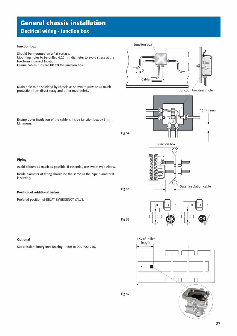
Junction box
Should be mounted on a fl at surface.Mounting holes to be drilled 6.25mm diameter to avoid stress at the box from incorrect location.Ensure cables runs are UP TO the junction box.
Drain hole to be shielded by chassis as shown to provide as much protection from direct spray and other road debris.
Ensure outer insulation of the cable is inside junction box by 5mm Minimum.
Piping
Avoid elbows as much as possible. If essential, use swept type elbow.
Inside diameter of fi tting should be the same as the pipe diameter it is serving.
Position of additional valves
Prefered position of RELAY EMERGENCY VALVE.
Optional
Suppression Emergency Braking - refer to 000 700 240.
Fig 55
Fig 56
Fig 57
Fig 54
Cable
Junction box
15mm min.
Outer insulation cable
Junction box
1/3 of trailer length
Junction box drain hole
38891 H:2738891 H:27 3/10/08 15:42:323/10/08 15:42:32
Auxiliary equipment wiringsecond title here
28
General Chassis installationElectrical wiring - ‘DIAG’ Side of vehicle connection
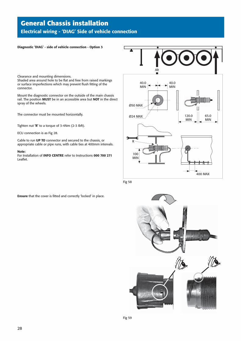
Diagnostic ‘DIAG’ - side of vehicle connection - Option 3
Clearance and mounting dimensions.Shaded area around hole to be fl at and free from raised markings or surface imperfections which may prevent fl ush fi tting of the connector.
Mount the diagnostic connector on the outside of the main chassis rail. The position MUST be in an accessible area but NOT in the direct spray of the wheels.
The connector must be mounted horizontally.
Tighten nut ‘R’ to a torque of 3-4Nm (2-3 Ibft).
ECU connection is as Fig 28.
Cable to run UP TO connector and secured to the chassis, or appropriate cable or pipe runs, with cable ties at 400mm intervals.
Note: For Installation of INFO CENTRE refer to Instructions 000 700 271 Leafl et.
Ensure that the cover is fi tted and correctly ‘locked’ in place.
Fig 58
Fig 59
Ø24 MAX
Ø50 MAX
40.0MIN
40.0MIN
400 MAX
100 MIN
R
Alt
120.0MIN
65.0MIN
38891 H:2838891 H:28 3/10/08 15:42:333/10/08 15:42:33
Auxiliary equipment wiringsecond title here
29
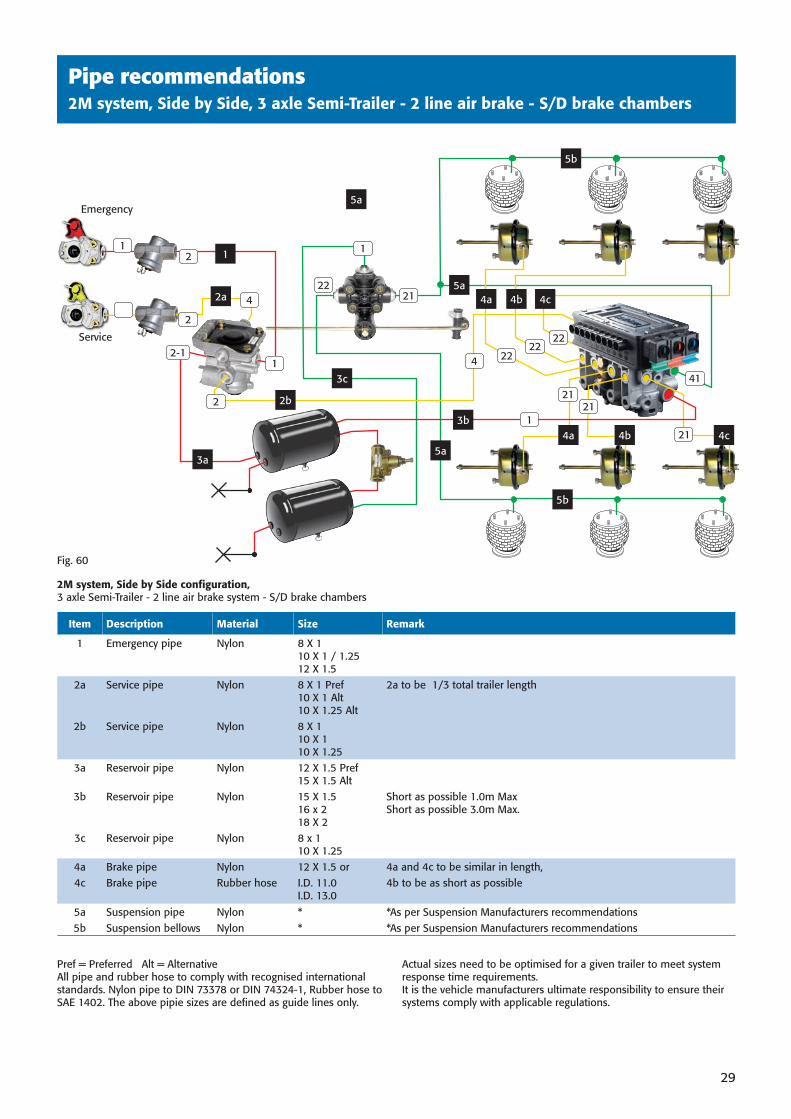
Pipe recommendations2M system, Side by Side, 3 axle Semi-Trailer - 2 line air brake - S/D brake chambers
2222
22
2121
21
413c
5a
5a
5a
5b
5b
4a 4b 4c
4a 4b 4c
1
2a
Emergency
Service
3b 1
1
2122
2b
4
3a
4
1
2
2-1
Pref = Preferred Alt = Alternative All pipe and rubber hose to comply with recognised international standards. Nylon pipe to DIN 73378 or DIN 74324-1, Rubber hose to SAE 1402. The above pipie sizes are defi ned as guide lines only.
Actual sizes need to be optimised for a given trailer to meet system response time requirements.It is the vehicle manufacturers ultimate responsibility to ensure their systems comply with applicable regulations.
Item Description Material Size Remark
1 Emergency pipe Nylon 8 X 1 10 X 1 / 1.25 12 X 1.5
2a Service pipe Nylon 8 X 1 Pref10 X 1 Alt10 X 1.25 Alt
2a to be 1/3 total trailer length
2b Service pipe Nylon 8 X 110 X 1 10 X 1.25
3a Reservoir pipe Nylon 12 X 1.5 Pref15 X 1.5 Alt
3b Reservoir pipe Nylon 15 X 1.516 x 218 X 2
Short as possible 1.0m MaxShort as possible 3.0m Max.
3c Reservoir pipe Nylon 8 x 110 X 1.25
4a Brake pipe Nylon 12 X 1.5 or 4a and 4c to be similar in length,4c Brake pipe Rubber hose I.D. 11.0
I.D. 13.04b to be as short as possible
5a Suspension pipe Nylon * *As per Suspension Manufacturers recommendations5b Suspension bellows Nylon * *As per Suspension Manufacturers recommendations
Fig. 60
2M system, Side by Side confi guration, 3 axle Semi-Trailer - 2 line air brake system - S/D brake chambers
12
2
38891 H:2938891 H:29 3/10/08 15:42:353/10/08 15:42:35
Auxiliary equipment wiringsecond title here
30
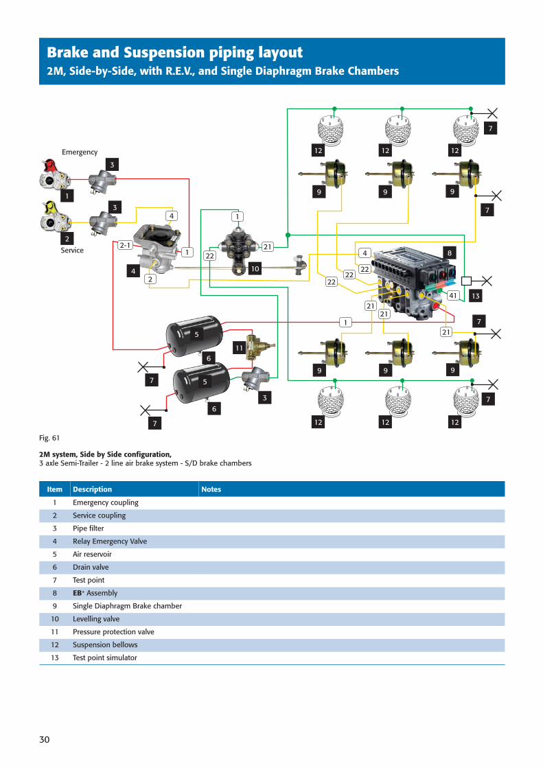
Brake and Suspension piping layout2M, Side-by-Side, with R.E.V., and Single Diaphragm Brake Chambers
4
2222
2121
211
41
Emergency
Service
22
121
4 10
7
7
7
9 9 9
9 9 9
7
7
8
13
3
3
3
11
1
2
7
5
12 12 12
12 12 12
4
2-1
2
1
22
Item Description Notes
1 Emergency coupling
2 Service coupling
3 Pipe fi lter
4 Relay Emergency Valve
5 Air reservoir
6 Drain valve
7 Test point
8 EB+ Assembly
9 Single Diaphragm Brake chamber
10 Levelling valve
11 Pressure protection valve
12 Suspension bellows
13 Test point simulator
Fig. 61
2M system, Side by Side confi guration, 3 axle Semi-Trailer - 2 line air brake system - S/D brake chambers
6
6
5
38891 H:3038891 H:30 3/10/08 15:42:463/10/08 15:42:46
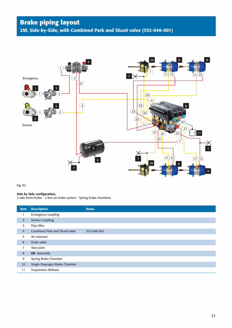
Brake piping layout2M, Side-by-Side, with Combined Park and Shunt valve (352-046-001)
31
Fig. 62
Side by Side confi guration, 3 axle Semi-Trailer - 2 line air brake system - Spring brake chambers
Emergency
Service
3
3
1
2
4
7
7
8
7
10
10 9 9
9
9
5
6
22
11
1
4
1
1
2
2
41
21
21
11 12 11 12
11 12 11 121
1
22
22
4
11
23
23
23
22
Item Description Notes
1 Emergency coupling
2 Service coupling
3 Pipe fi lter
4 Combined Park and Shunt valve 352-046-001
5 Air reservoir
6 Drain valve
7 Test point
8 EB+ Assembly
9 Spring Brake Chamber
10 Single Diapragm Brake Chamber
11 Suspension Bellows
23
11
7
21
38891 H:3138891 H:31 3/10/08 15:42:553/10/08 15:42:55
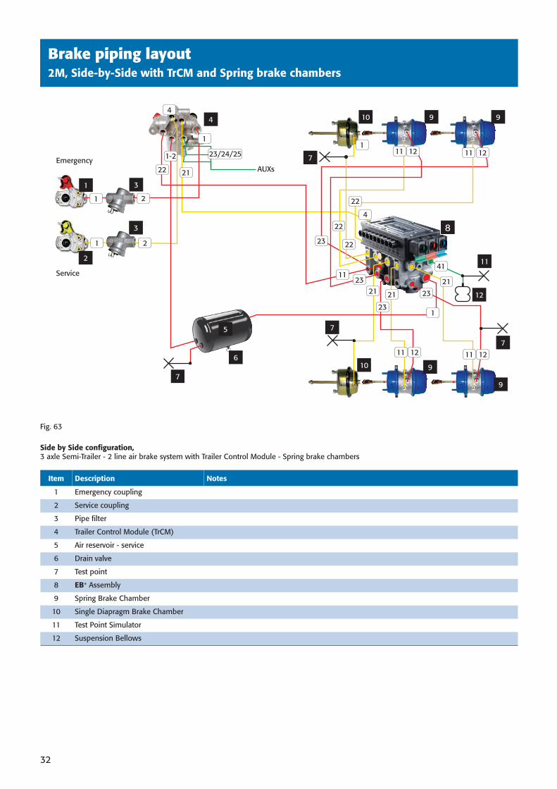
Brake piping layout2M, Side-by-Side with TrCM and Spring brake chambers
32
Fig. 63
Side by Side confi guration, 3 axle Semi-Trailer - 2 line air brake system with Trailer Control Module - Spring brake chambers
Emergency
Service
3
3
1
2
4
7
7
8
7
10
10 9 9
5
6
21
1-2
1
1
1
2
2
41
2121 21
11 12 11 12
11 12 11 121
1
22
22
22
4
11
23
23
23
AUXs
9
9
22
11
12
4
Item Description Notes
1 Emergency coupling
2 Service coupling
3 Pipe fi lter
4 Trailer Control Module (TrCM)
5 Air reservoir - service
6 Drain valve
7 Test point
8 EB+ Assembly
9 Spring Brake Chamber
10 Single Diapragm Brake Chamber
11 Test Point Simulator
12 Suspension Bellows
7
23
23/24/25
38891 H:3238891 H:32 3/10/08 15:43:023/10/08 15:43:02
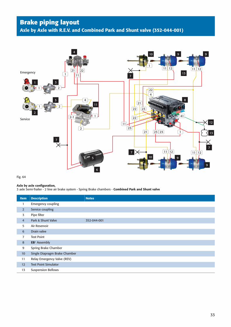
Brake piping layoutAxle by Axle with R.E.V. and Combined Park and Shunt valve (352-044-001)
33
Fig. 64
Axle by axle confi guration, 3 axle Semi-Trailer - 2 line air brake system - Spring Brake chambers - Combined Park and Shunt valve
Item Description Notes
1 Emergency coupling
2 Service coupling
3 Pipe fi lter
4 Park & Shunt Valve 352-044-001
5 Air Reservoir
6 Drain valve
7 Test Point
8 EB+ Assembly
9 Spring Brake Chamber
10 Single Diapragm Brake Chamber
11 Relay Emergency Valve (REV)
12 Test Point Simulator
13 Suspension Bellows
5
6
Emergency
Service
3
3
1
2
4
7
7
7
8
10
10 9 9
9
9
22
111
4
1
1
2
2
41
23
11 11 12
11 12 111
1
22
4
2-1
2
11
13
12
12
13
21 12
23
22
11
23 23
1
21
22
21
7
38891 H:3338891 H:33 3/10/08 15:43:103/10/08 15:43:10
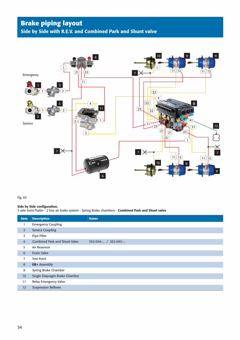
Brake piping layoutSide by Side with R.E.V. and Combined Park and Shunt valve
34
5
6
Emergency
Service
3
3
1
2
4
7 7 7
8
7
10
10 9 9
9
9
22
11
1
4
1
1
2
2
41
2121 21
11 12 11 12
11 12 11 121
1
22
22
22
4
11
23
23
23
21
12-1
2
11
1223
Fig. 65
Side by Side confi guration, 3 axle Semi-Trailer - 2 line air brake system - Spring Brake chambers - Combined Park and Shunt valve
Item Description Notes
1 Emergency Coupling
2 Service Coupling
3 Pipe Filter
4 Combined Park and Shunt Valve 352-044-... / 352-045-...
5 Air Reservoir
6 Drain Valve
7 Test Point
8 EB+ Assembly
9 Spring Brake Chamber
10 Single Diapragm Brake Chamber
11 Relay Emergency Valve
12 Suspension Bellows
38891 H:3438891 H:34 3/10/08 15:43:183/10/08 15:43:18
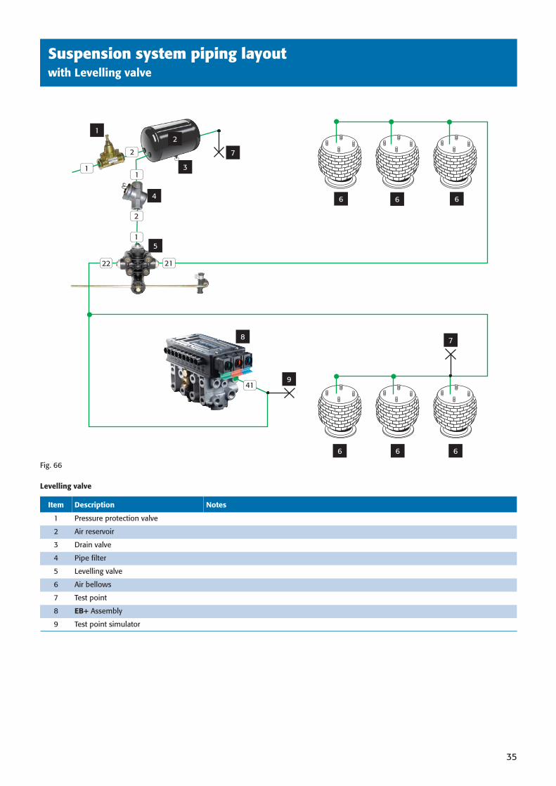
Suspension system piping layoutwith Levelling valve
35
2
3
4
1
2
1
2
5
6 6
7
941
1
22
1
6 6 6
6
8
21
7
Fig. 66
Levelling valve
Item Description Notes
1 Pressure protection valve
2 Air reservoir
3 Drain valve
4 Pipe fi lter
5 Levelling valve
6 Air bellows
7 Test point
8 EB+ Assembly
9 Test point simulator
38891 H:3538891 H:35 3/10/08 15:43:263/10/08 15:43:26
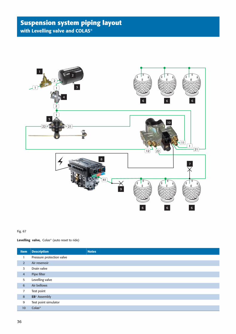
Suspension system piping layoutwith Levelling valve and COLAS®
36
2
3
4
1
2
1
2
5
6 6
7
9
41
1
1
6 6 6
6
8
102122
12 22 211
11
Fig. 67
Levelling valve, Colas® (auto reset to ride)
Item Description Notes
1 Pressure protection valve
2 Air reservoir
3 Drain valve
4 Pipe fi lter
5 Levelling valve
6 Air bellows
7 Test point
8 EB+ Assembly
9 Test point simulator
10 Colas®
38891 H:3638891 H:36 3/10/08 15:43:313/10/08 15:43:31
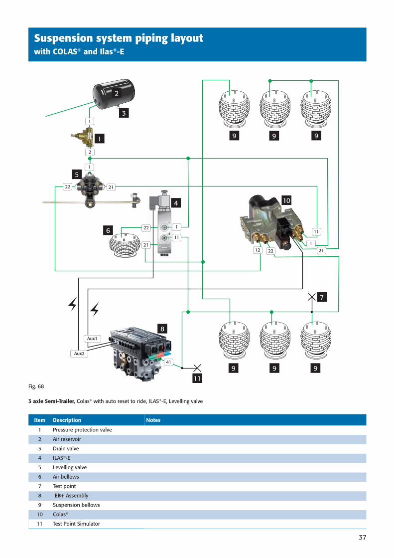
Suspension system piping layoutwith COLAS® and Ilas®-E
37
Fig. 68
3 axle Semi-Trailer, Colas® with auto reset to ride, ILAS®-E, Levelling valve
2
3
1
1
5
9 9
7
11
419 9 9
9
8
10
12 22
1
11
21
21
Aux1
Aux2
2
4
1
21
22
116
1
22
Item Description Notes
1 Pressure protection valve
2 Air reservoir
3 Drain valve
4 ILAS®-E
5 Levelling valve
6 Air bellows
7 Test point
8 EB+ Assembly
9 Suspension bellows
10 Colas®
11 Test Point Simulator
38891 H:3738891 H:37 3/10/08 15:43:383/10/08 15:43:38
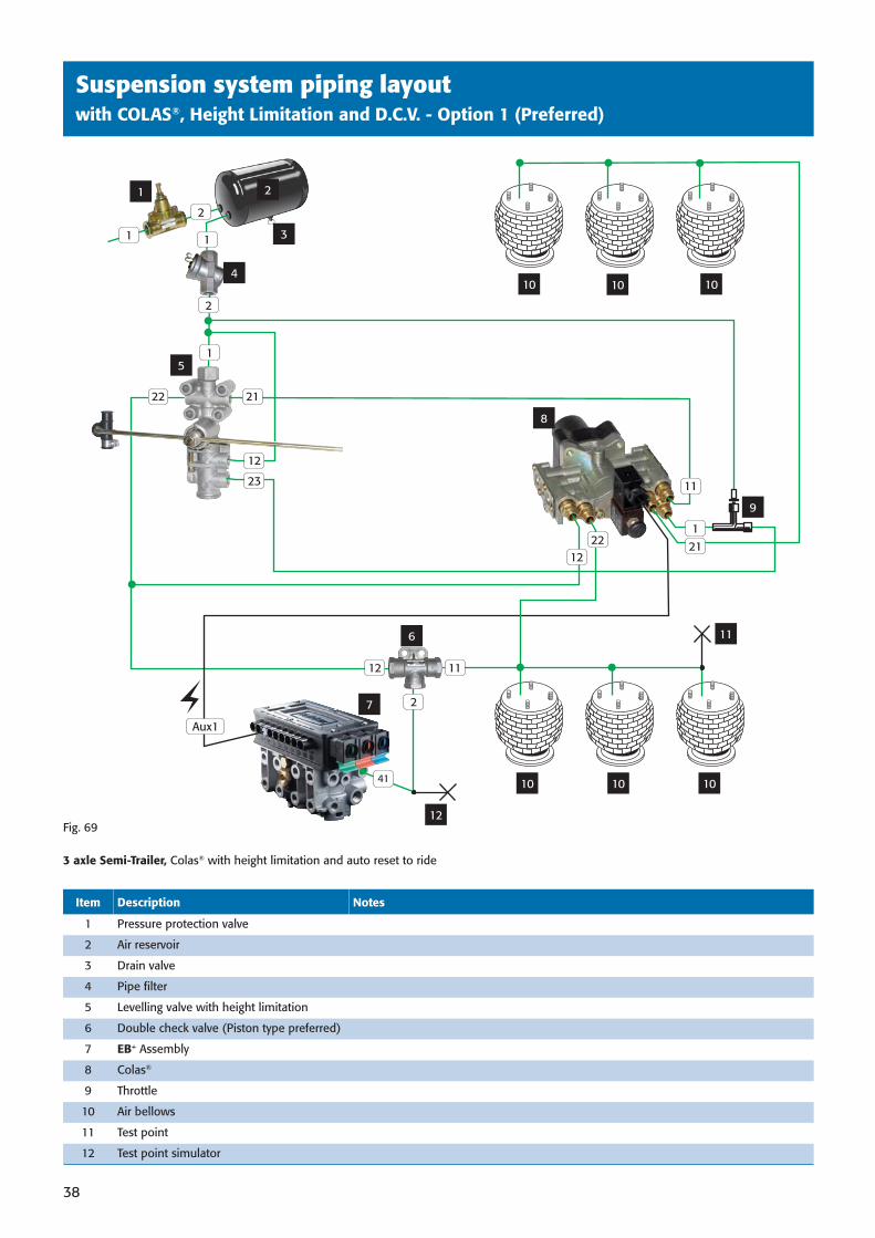
Suspension system piping layoutwith COLAS®, Height Limitation and D.C.V. - Option 1 (Preferred)
38
Fig. 69
3 axle Semi-Trailer, Colas® with height limitation and auto reset to ride
2
3
1
5
10 10
11
12
41 10 10 10
10
7
8
11
21
Aux1
2
4
11
2
21
12 11
2
6
1
1
9
22
Item Description Notes
1 Pressure protection valve
2 Air reservoir
3 Drain valve
4 Pipe fi lter
5 Levelling valve with height limitation
6 Double check valve (Piston type preferred)
7 EB+ Assembly
8 Colas®
9 Throttle
10 Air bellows
11 Test point
12 Test point simulator
12
23
1222
38891 H:3838891 H:38 3/10/08 15:43:443/10/08 15:43:44
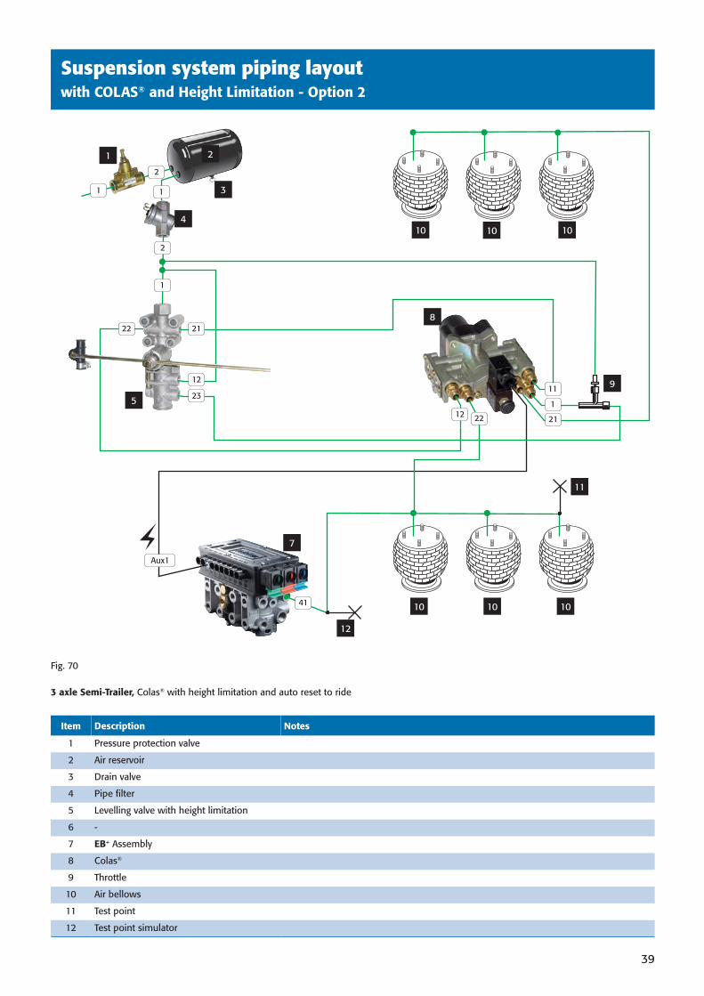
Suspension system piping layoutwith COLAS® and Height Limitation - Option 2
39
Fig. 70
3 axle Semi-Trailer, Colas® with height limitation and auto reset to ride
2
3
1
5
10 10
11
12
41 10 10 10
10
7
8
1
11
21
Aux1
2
4
11
2
21
23
1
22
9
Item Description Notes
1 Pressure protection valve
2 Air reservoir
3 Drain valve
4 Pipe fi lter
5 Levelling valve with height limitation
6 -
7 EB+ Assembly
8 Colas®
9 Throttle
10 Air bellows
11 Test point
12 Test point simulator
12
12 22
38891 H:3938891 H:39 3/10/08 15:43:533/10/08 15:43:53
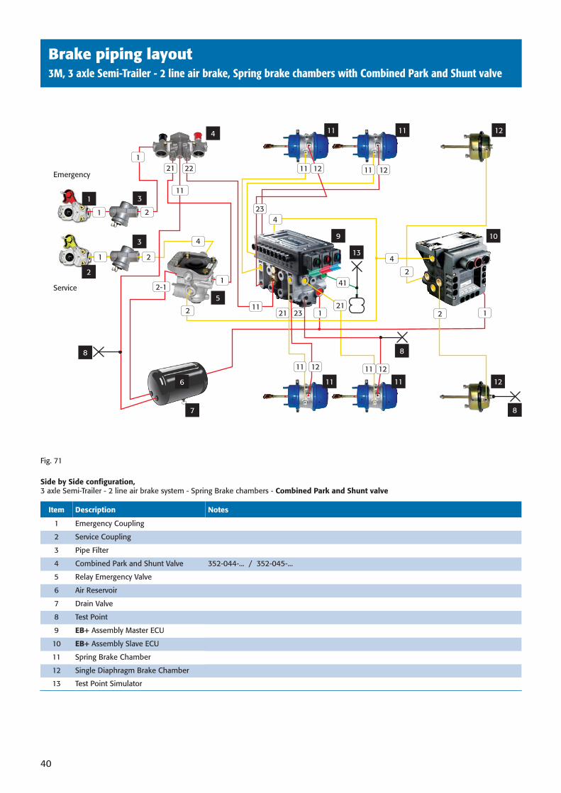
Item Description Notes
1 Emergency Coupling
2 Service Coupling
3 Pipe Filter
4 Combined Park and Shunt Valve 352-044-... / 352-045-...
5 Relay Emergency Valve
6 Air Reservoir
7 Drain Valve
8 Test Point
9 EB+ Assembly Master ECU
10 EB+ Assembly Slave ECU
11 Spring Brake Chamber
12 Single Diaphragm Brake Chamber
13 Test Point Simulator
40
Brake piping layout3M, 3 axle Semi-Trailer - 2 line air brake, Spring brake chambers with Combined Park and Shunt valve
Fig. 71
Side by Side confi guration, 3 axle Semi-Trailer - 2 line air brake system - Spring Brake chambers - Combined Park and Shunt valve
6
7
Emergency
Service
3
3
1
2
4
8
11 11 12
11 11 12
109
22
11
1
4
1
1
2
2
11 12
11
12 11 12
1123
23
21
21
12-1
2
5
13
12
8
8
11
2
2
4
4
41
21
11
38891 H:4038891 H:40 3/10/08 15:44:003/10/08 15:44:00
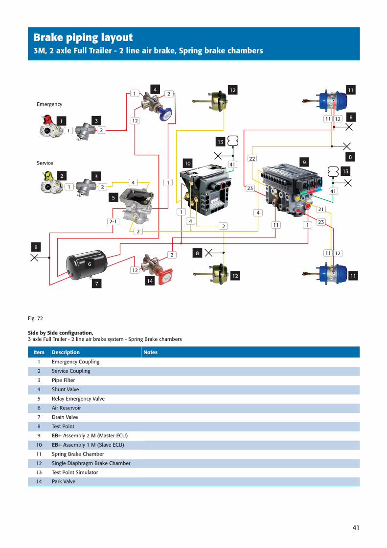
Brake piping layout3M, 2 axle Full Trailer - 2 line air brake, Spring brake chambers
41
Item Description Notes
1 Emergency Coupling
2 Service Coupling
3 Pipe Filter
4 Shunt Valve
5 Relay Emergency Valve
6 Air Reservoir
7 Drain Valve
8 Test Point
9 EB+ Assembly 2 M (Master ECU)
10 EB+ Assembly 1 M (Slave ECU)
11 Spring Brake Chamber
12 Single Diaphragm Brake Chamber
13 Test Point Simulator
14 Park Valve
Fig. 72
Side by Side confi guration, 3 axle Full Trailer - 2 line air brake system - Spring Brake chambers
Emergency
Service
3
4
14
3
5
1
2
12 11
1112
1
1
2
1
1
2
98
8
8
13
13
10
6
7
8
41
41
12
11
11
12
12
21
22
23
23
111
4
4
4
2
2
2
1
2-1
2
12
38891 H:4138891 H:41 3/10/08 15:44:093/10/08 15:44:09

Auxiliary equipment wiringsecond title here
42
Fig. 73
Semi-Trailer and Centre Axle Trailer Installation Option
N1 MAXIMUM length of cable between ISO 1185(24N) connector and front junction box to be 1m.Failure to comply with the above recommendation may result in insuffi cient voltage at the ECU.
SENSOR2 Core - PUR2 x 0.75mm²
ISO 7638 7 Core - PUR5 x 1.5mm²2 x 4.0mm²
Safety back-up2 Core - PUR2 x 1.5mm²
AUXILIARY3 Core - PUR3 x 0.75mm²
(2 cores used)
DIAGNOSTIC4 Core - PUR4 x 0.75mm²
ISO 7638
ISO 1185(24N)
INFO CENTRE or SIDE OF VEHICLE
CONNECTOR
Wiring schematic
38891 H:4238891 H:42 3/10/08 15:44:173/10/08 15:44:17
Auxiliary equipment wiringsecond title here
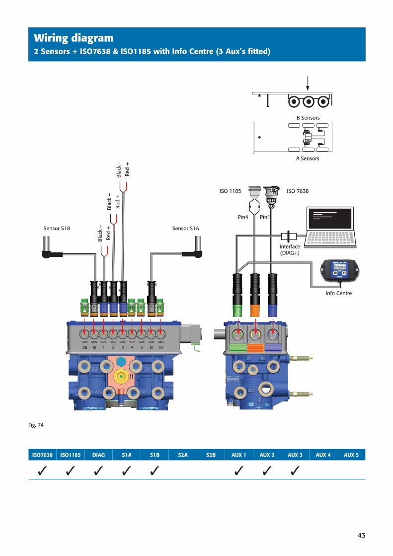
43
Wiring diagram2 Sensors + ISO7638 & ISO1185 with Info Centre (3 Aux’s fi tted)
Pin1Pin4
ISO 1185 ISO 7638
Interface (DIAG+)
Info Centre
Sensor S1ASensor S1B
Red
+
Bla
ck –
Red
+
Bla
ck –
Red
+
Bla
ck –
A Sensors
B Sensors
Fig. 74
ISO7638 ISO1185 DIAG S1A S1B S2A S2B AUX 1 AUX 2 AUX 3 AUX 4 AUX 5
✓ ✓ ✓ ✓ ✓ ✓ ✓ ✓
38891 H:4338891 H:43 3/10/08 15:44:183/10/08 15:44:18
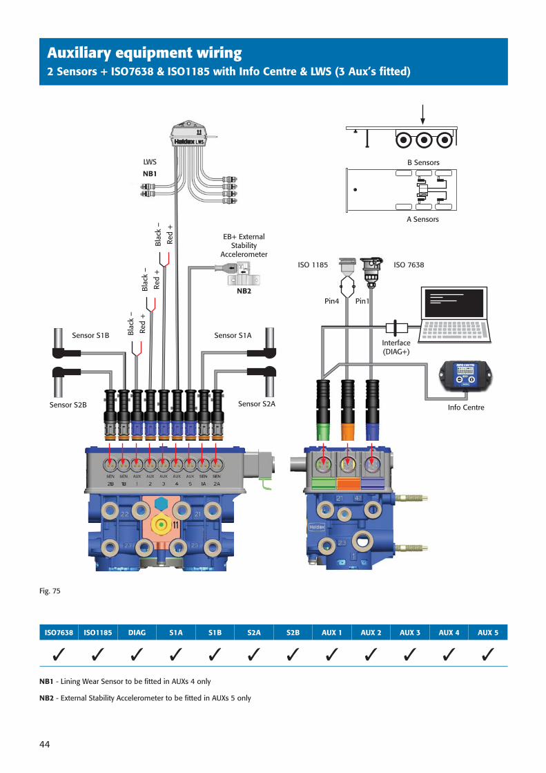
Auxiliary equipment wiringsecond title here
44
Auxiliary equipment wiring2 Sensors + ISO7638 & ISO1185 with Info Centre & LWS (3 Aux’s fi tted)
Pin1Pin4
ISO 1185 ISO 7638
Interface (DIAG+)
Info Centre
LWS
Sensor S1A
Sensor S2A
Sensor S1B
Sensor S2B
Red
+
Bla
ck –
Red
+
Bla
ck –
Red
+
Bla
ck –
NB2
EB+ External Stability
Accelerometer
A Sensors
B Sensors
ISO7638 ISO1185 DIAG S1A S1B S2A S2B AUX 1 AUX 2 AUX 3 AUX 4 AUX 5
✓ ✓ ✓ ✓ ✓ ✓ ✓ ✓ ✓ ✓ ✓ ✓
NB1 - Lining Wear Sensor to be fi tted in AUXs 4 only
NB2 - External Stability Accelerometer to be fi tted in AUXs 5 only
NB1
Fig. 75
38891 H:4438891 H:44 3/10/08 15:44:213/10/08 15:44:21
Auxiliary equipment wiringsecond title here
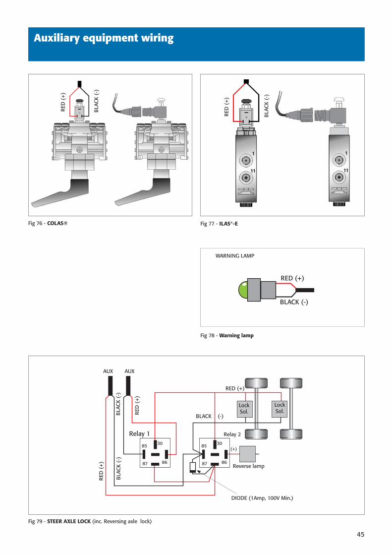
45
Fig 76 - COLAS®
Fig 78 - Warning lamp
Fig 79 - STEER AXLE LOCK (inc. Reversing axle lock)
Fig 77 - ILAS®-E
BLACK (-)
RED (+)
WARNING LAMP
RED (+)
(+)
BLACK (-)BLA
CK
(-)
RED
(+
)
BLA
CK
(-)
RED
(+
)
AUX AUX
Reverse lamp
Relay 2Relay 1
DIODE (1Amp, 100V Min.)
85 30
8687
85 30
8687
Lock Sol.
Lock Sol.
BLA
CK
(-)
RED
(+
)
BLA
CK
(-)
RED
(+
)
Auxiliary equipment wiring
38891 H:4538891 H:45 3/10/08 15:44:253/10/08 15:44:25
46
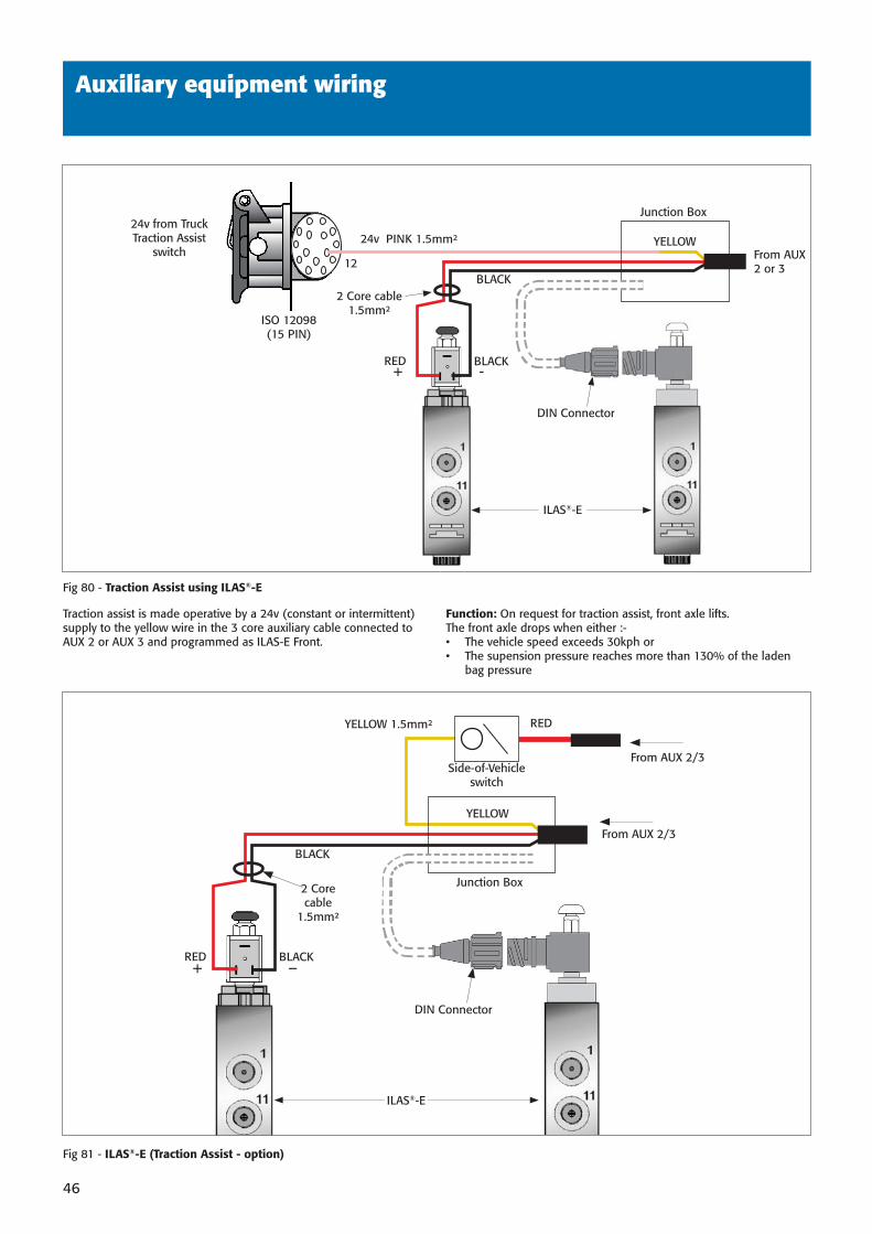
Auxiliary equipment wiring
Traction assist is made operative by a 24v (constant or intermittent) supply to the yellow wire in the 3 core auxiliary cable connected to AUX 2 or AUX 3 and programmed as ILAS-E Front.
Function: On request for traction assist, front axle lifts.The front axle drops when either :-• The vehicle speed exceeds 30kph or• The supension pressure reaches more than 130% of the laden
bag pressure
Fig 80 - Traction Assist using ILAS®-E
RED + -
2 Core cable1.5mm²
BLACK
ISO 12098(15 PIN)
12
24v PINK 1.5mm²
Junction Box
YELLOW
BLACK
24v from TruckTraction Assist
switch From AUX 2 or 3
DIN Connector
RED + –
2 Core cable
1.5mm²
BLACK
YELLOW
BLACK
From AUX 2/3
From AUX 2/3Side-of-Vehicle
switch
YELLOW 1.5mm² RED
Junction Box
ILAS®-E
ILAS®-E
Fig 81 - ILAS®-E (Traction Assist - option)
DIN Connector
38891 H:4638891 H:46 3/10/08 15:44:263/10/08 15:44:26
47
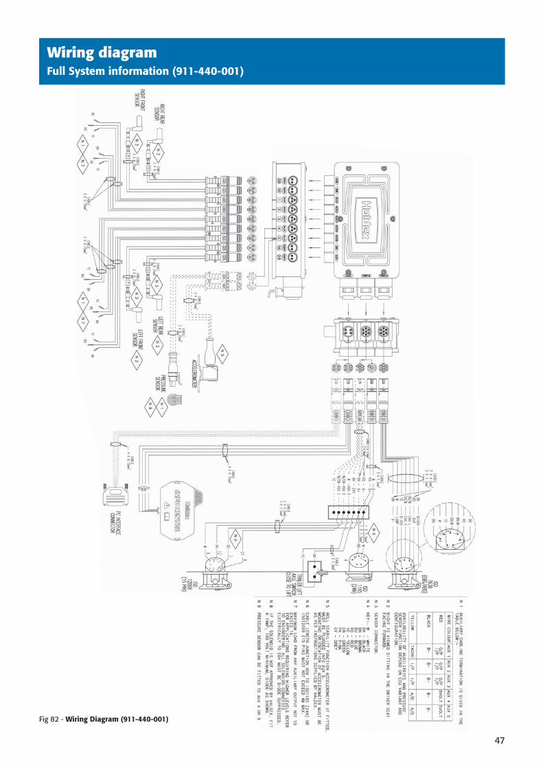
Wiring diagramFull System information (911-440-001)
DIAGRAM to be supplied
Fig 82 - Wiring Diagram (911-440-001)
38891 H:4738891 H:47 3/10/08 15:44:263/10/08 15:44:26
48
Hazardous Goods/ADR Installations
Introduction
Vehicles equipped to transport hazardous goods or explosive substances are required to have electrical systems with specifi ed levels of safety and protection. These requirements are defi ned in the European Agreement on International Transport of Dangerous Goods by Road (ADR 2007)’.
The ADR requirements apply to the following classes of dangerous load carrying vehicles:EX/II, EX/III, FL, OX, and AT.
The following key points should be observed on Hazardous Goods/ADR trailer installations.
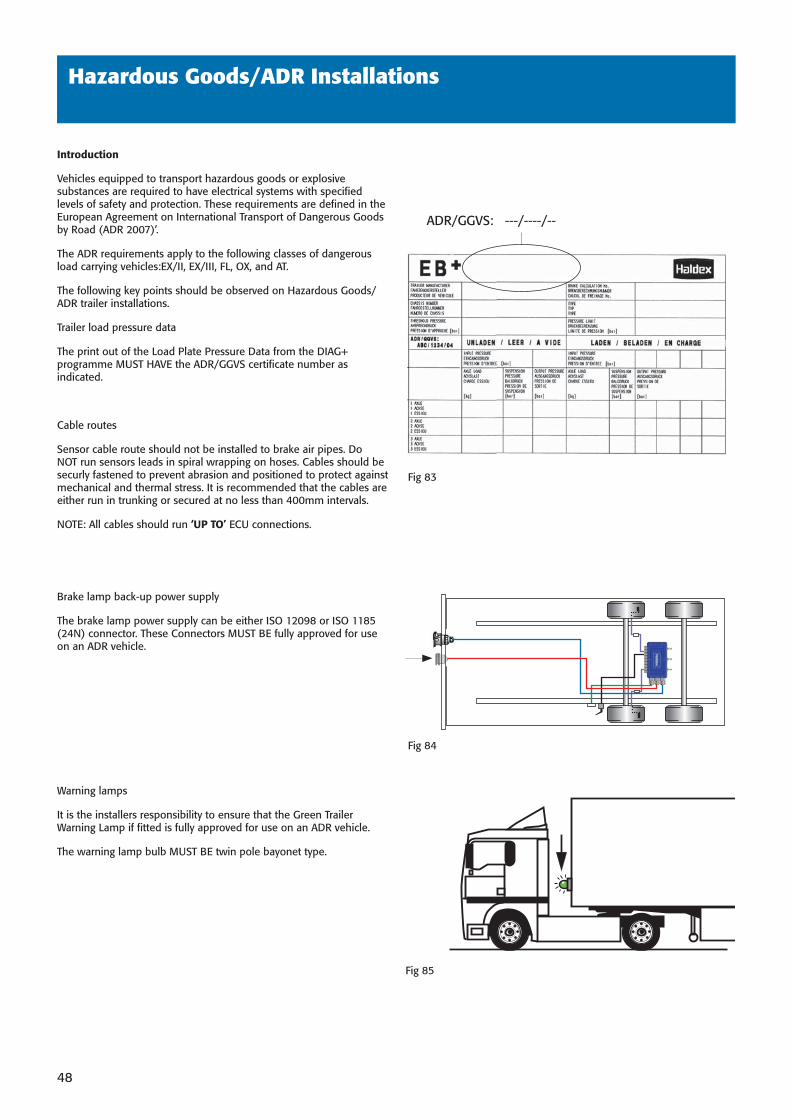
Trailer load pressure data
The print out of the Load Plate Pressure Data from the DIAG+ programme MUST HAVE the ADR/GGVS certifi cate number as indicated.
Cable routes
Sensor cable route should not be installed to brake air pipes. Do NOT run sensors leads in spiral wrapping on hoses. Cables should be securly fastened to prevent abrasion and positioned to protect against mechanical and thermal stress. It is recommended that the cables are either run in trunking or secured at no less than 400mm intervals.
NOTE: All cables should run ‘UP TO’ ECU connections.
Brake lamp back-up power supply
The brake lamp power supply can be either ISO 12098 or ISO 1185 (24N) connector. These Connectors MUST BE fully approved for use on an ADR vehicle.
Warning lamps
It is the installers responsibility to ensure that the Green Trailer Warning Lamp if fi tted is fully approved for use on an ADR vehicle.
The warning lamp bulb MUST BE twin pole bayonet type.
Fig 84
Fig 85
Fig 83
ADR/GGVS: ---/----/--
38891 H:4838891 H:48 3/10/08 15:44:363/10/08 15:44:36
49
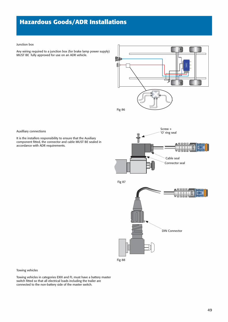
Junction box
Any wiring required to a junction box (for brake lamp power supply) MUST BE fully approved for use on an ADR vehicle.
Auxilliary connections
It is the installers responsibility to ensure that the Auxiliary component fi tted, the connector and cable MUST BE sealed in accordance with ADR requirements.
Towing vehicles
Towing vehicles in categories EXIII and FL must have a battery master switch fi tted so that all electrical loads including the trailer are connected to the non-battery side of the master switch.
Hazardous Goods/ADR Installations
Fig 87
Fig 86
Screw +‘O’ ring seal
Cable seal
Connector seal
Fig 88
DIN Connector
38891 H:4938891 H:49 3/10/08 15:44:373/10/08 15:44:37
50
Programming
To complete the EB+ installation the ECU must be programmed
using DIAG+ software.
Refer to DIAG+ User Guide 000 700 255 for further information.
38891 H:5038891 H:50 3/10/08 15:44:383/10/08 15:44:38
51
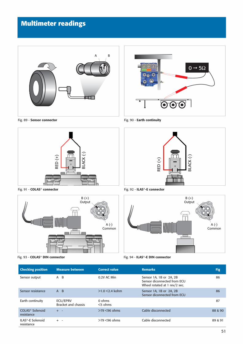
Multimeter readings
Fig. 89 - Sensor connector
Checking position Measure between Correct value Remarks Fig
Sensor output A B 0.2V AC Min Sensor 1A, 1B or 2A, 2B Sensor diconnected from ECU Wheel rotated at 1 rev/2 sec.
86
Sensor resistance A B >1.0 <2.4 kohm Sensor 1A, 1B or 2A, 2B Sensor diconnected from ECU
86
Earth continuity ECU/EPRVBracket and chassis
0 ohms<5 ohms
87
COLAS® Solenoidresistance
+ - >79 <96 ohms Cable disconnected 88 & 90
ILAS®-E Solenoidresistance
+ - >79 <96 ohms Cable disconnected 89 & 91
Fig. 91 - COLAS® connector
Fig. 90 - Earth continuity
Fig. 92 - ILAS®-E connector
BA
0 5
BLA
CK
(-)
RED
(+
)
BLA
CK
(-)
RED
(+
)
Fig. 93 - COLAS® DIN connector Fig. 94 - ILAS®-E DIN connector
A (-)Common
B (+)Output
A (-)Common
B (+)Output
38891 H:5138891 H:51 3/10/08 15:44:383/10/08 15:44:38
www.haldex.comwww.brake-eu.haldex.com
Commercial Vehicle Systems
000 700 340_GB/09.2008/Redditch/10.2008
AustriaHaldex Wien Ges.m.b.H.ViennaTel.: +43 1 8 69 27 97Fax: +43 1 8 69 27 97 27E-Mail: [email protected]
BelgiumHaldex N.V./S.A.Balegem Tel.: +32 9 363 90 00Fax: +32 9 363 90 09E-Mail: [email protected]
BrazilHaldex do BrasilSão PauloTel.: +55 11 213 55 000Fax: +55 11 503 49 515E-Mail: [email protected]
CanadaHaldex LtdGuelph, OntarioTél.: +1 519 826 7723Fax :+1 519 826 9497E-Mail: [email protected]
ChinaHaldex International Trading Co. Ltd.ShanghaiTel.: +86 21 5240 0338Fax: +86 21 5240 0177E-Mail: [email protected]
FranceHaldex Europe SASWeyersheim (Strasbourg)Tel.: +33 3 88 68 22 00Fax: +33 3 88 68 22 09E-Mail: [email protected]
Germany Haldex Brake Products GmbHHeidelbergTel.: +49 6221 7030Fax: +49 6221 703400E-Mail: [email protected]
HungaryHaldex Hungary Kft.SzentlörinckátaTel.: +36 29 631 300Fax: +36 29 631 301E-Mail : [email protected]
IndiaHaldex India LimitedNasikTel.: +91 253 2380094Fax +91 253 2380729E-Mail : [email protected]
ItalyHaldex Italia Srl.Biassono (Milan)Tel.: +39 039 47 17 02Fax: +39 039 27 54 309E-Mail: [email protected]
PolandHaldex Sp. z.o.o.PraszkaTel.: +48 34 350 11 00Fax: +48 34 350 11 11E-Mail: [email protected]
RussiaOOO Haldex RUSMoscowTel..: + 7 495 747 59 56Fax: +7 495 786 39 70E-Mail: [email protected] South KoreaHaldex Korea Ltd.SeoulTel.: +82 2 2636 7545Fax: +82 2 2636 7548E-Mail: [email protected]
SpainHaldex España S.A.Parets del Valles (Barcelona)Tel.: +34 93 573 10 30Fax: +34 93 573 07 28E-Mail: [email protected]
SwedenHaldex Brake Products ABLandskronaTel.: +46 418 47 60 00Fax: +46 418 47 60 01E-Mail: [email protected]
United KingdomHaldex Ltd.Newton AycliffeTel.: +44 1325 310 110Fax: +44 1325 311 834E-Mail: [email protected]
Haldex Brake Products Ltd.RedditchTel.: +44 1527 499 499Fax: +44 1527 499 500E-Mail: [email protected]
USAHaldex Brake Products Corp.Kansas City MOTel.: +1 816 891 2470Fax: +1 816 891 9447E-Mail : [email protected]
Haldex offers proprietary vehicle technology solutions to the global vehicle industry within specifi c niches. We focus on products to improve safety, the environment and vehicle dynamics.
We are enhancing our competitive capabilities and building long-term customer relationships through high performance, low total costs to the customer throughout the product’s service life, ethical business practices and commitment to long-term partnerships. Haldex operations are divided into four business areas: Commercial Vehicle Systems, Hydraulic Systems, Garphyttan Wire and Traction Systems.
©2007, Haldex AB. This material may contain Haldex trademarks and third party trademarks, trade names, corporate logos, graphics and emblems which are the property of their respective companies. The contents of this document may not be copied, distributed, adapted or displayed for commercial purposes or otherwise without prior written consent from Haldex.
38891 238891 2 3/10/08 15:40:253/10/08 15:40:25