Embed Size (px)
Citation preview

BRAKE CONTROL – ELECTRONICALLY CONTROLLED BRAKE SYSTEM BC–1
BC
ELECTRONICALLY CONTROLLED BRAKE SYSTEMPRECAUTION1. TROUBLESHOOTING PRECAUTION
(a) When there is a malfunction with terminal contact points or part installation problems, removal and installation of the suspected problem parts may return the system to the normal condition either completely or temporarily.
(b) In order to determine the malfunctioning area, be sure to check the conditions at the time the malfunction occurred, such as DTC output and the freeze frame data, and record it before disconnecting each connector or removing and installing parts.
(c) Since the system may be influenced by malfunctions in systems other than the brake control system, be sure to check for DTCs in other systems.
2. HANDLING PRECAUTION(a) Do not remove or install the Enhanced VSC or
Electronically Controlled Brake (ECB) parts such as the steering sensor, yaw rate sensor or brake pedal stroke sensor except when required, as they need to be adjusted correctly after removal or installation.
(b) Be sure to perform preparation before work and confirmation after work is completed by following the directions in the repair manual when working on the Enhanced VSC or ECB system.
(c) Be sure to remove and install the ECU, actuator, each sensor, etc. with the power switch OFF unless otherwise specified in the inspection procedure.
(d) Be sure to remove the 2 main relays before removal and installation, or replacement of the Enhanced VSC or ECB parts.
(e) The removal or installation of the actuator, master cylinder or stroke simulator as well as some other procedures can cause the fluid level to drop below the fluid reservoir port. If this happens when performing such work, be sure to remove the 2 motor relays until the bleeding of the air in the pipeline is completed.HINT:• When the pump motor is operated with the air in
the brake actuator hose, bleeding the air becomes difficult due to air in the actuator.
• The skid control ECU may operate the stroke simulator and drive the pump motor even when the power switch is OFF.
BC–2 BRAKE CONTROL – ELECTRONICALLY CONTROLLED BRAKE SYSTEM
BC
• The ECB system has its own auxiliary power source. This system can be operated after disconnecting the negative terminal from the auxiliary battery (12 V) until the discharge is completed.
• With the power switch OFF, the skid control ECU can be operated for 2 minutes after the brake operation is finished.
(f) Removal of the main relay and motor relay(1) Wait for 2 minutes after turning the power switch
OFF, stopping the brake pedal operation and closing the driver door before removing the 2 relays.HINT:The above situation occurs when the pump motor operates to prepare for the next operation just before brake control system turns off.
(g) When removing and installing the ECU, actuator and each sensor, be sure to check that the normal display is output in test mode inspection and in DTC output inspection after installing all the parts.
3. DTC PRECAUTION(a) Warnings for some DTCs cannot be cleared only by
repairing the malfunctioning parts. If the warning is displayed after repair work, the DTC should be cleared after turning the power switch OFF.NOTICE:If a DTC is cleared but the malfunction still continues, the DTC is stored again.
4. FAIL-SAFE PRECAUTION(a) When trouble occurs in the brake control systems,
the skid control ECU lights up the warning lights (ECB, ABS, Enhanced VSC and BRAKE) corresponding to the malfunctioning systems and prohibits ABS, Enhanced VSC and brake assist operation.
(b) The control of the ECB can be continued by only the normal parts according to the malfunction.HINT:• If control of the ECB for any of the 4 wheels is
prohibited, that wheel loses brake booster function or braking ability.
• If one of the 4 wheels loses brake booster function, the feel when depressing brake pedal changes as the stroke simulator (pedal reactive force generating solenoid) operation is prohibited.
• If control of the ECB for all wheels is prohibited, the 2 front wheels lose brake booster function.
BRAKE CONTROL – ELECTRONICALLY CONTROLLED BRAKE SYSTEM BC–3
BC
5. DRUM TESTER PRECAUTION(a) When using the drum tester, be sure to follow the
procedures below to prohibit the Enhanced VSC operation.NOTICE:• Make sure that the Enhanced VSC warning
light is blinking (change to TEST MODE).• Secure the vehicle with the lock chain for
safety.6. CAN COMMUNICATION SYSTEM PRECAUTION
(a) The CAN communication system is used for the data communication between the skid control ECU, the steering sensor, the yaw rate sensor (deceleration sensor included) and other ECUs. If there is trouble with the CAN communication line, corresponding DTCs in the communication line are output.
(b) If a CAN communication line DTC is output, repair the malfunction in the communication line and troubleshoot the Enhanced VSC system while data communication is normal.
(c) Since the CAN communication line has its own length and route, it cannot be repaired temporarily with a bypass wire, etc.
7. NOTICES FOR INITIALIZATIONNOTICE:When disconnecting the cable from the negative (-) battery terminal, initialize the following system after the cable is reconnected.
8. NOTICES(a) FOR HYBRID SYSTEM ACTIVATION
• When the warning light is illuminated or the battery has been disconnected and reconnected, pressing the power switch may not start the system on the first try. If so, press the power switch again.
• With the power switch's power mode changed to ON (IG), disconnect the battery. If the key is not in the key slot during reconnection, DTC B2799 may be output.
System Name See Procedure
Power Window Control System IN-32
BC–4 BRAKE CONTROL – ELECTRONICALLY CONTROLLED BRAKE SYSTEM
BC
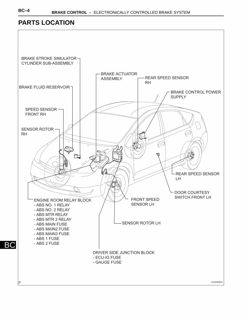
PARTS LOCATION
SENSOR ROTOR
RH
SPEED SENSOR
FRONT RH
BRAKE FLUID RESERVOIR
REAR SPEED SENSOR
RH
BRAKE CONTROL POWER
SUPPLY
REAR SPEED SENSOR
LH
DRIVER SIDE JUNCTION BLOCK
- ECU-IG FUSE
- GAUGE FUSE
FRONT SPEED
SENSOR LH
SENSOR ROTOR LH
ENGINE ROOM RELAY BLOCK
- ABS NO. 1 RELAY
- ABS NO. 2 RELAY
- ABS MTR RELAY
- ABS MTR 2 RELAY
- ABS MAIN FUSE
- ABS MAIN2 FUSE
- ABS MAIN3 FUSE
- ABS 1 FUSE
- ABS 2 FUSE
DOOR COURTESY
SWITCH FRONT LH
BRAKE ACTUATOR
ASSEMBLY
BRAKE STROKE SIMULATOR
CYLINDER SUB-ASSEMBLY
C116292E01
BRAKE CONTROL – ELECTRONICALLY CONTROLLED BRAKE SYSTEM BC–5
BC
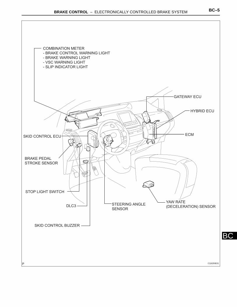
COMBINATION METER
- BRAKE CONTROL WARNING LIGHT
- BRAKE WARNING LIGHT
- VSC WARNING LIGHT
- SLIP INDICATOR LIGHT
SKID CONTROL ECU
BRAKE PEDAL
STROKE SENSOR
DLC3
SKID CONTROL BUZZER
GATEWAY ECU
HYBRID ECU
ECM
YAW RATE
(DECELERATION) SENSORSTEERING ANGLE
SENSOR
STOP LIGHT SWITCH
C116293E01
BC–6 BRAKE CONTROL – ELECTRONICALLY CONTROLLED BRAKE SYSTEM
BC
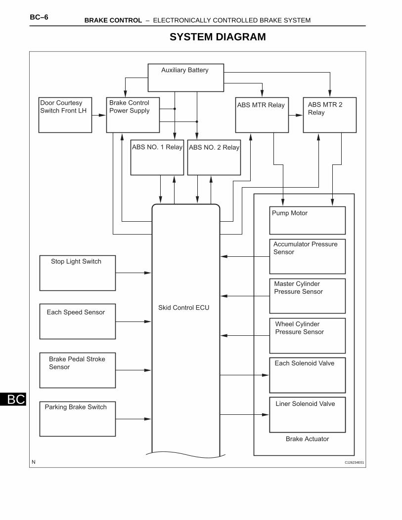
SYSTEM DIAGRAM
Auxiliary Battery
Door Courtesy
Switch Front LH
Brake Control
Power Supply
ABS NO. 1 Relay ABS NO. 2 Relay
ABS MTR Relay ABS MTR 2
Relay
Pump Motor
Accumulator Pressure
Sensor
Master Cylinder
Pressure Sensor
Wheel Cylinder
Pressure Sensor
Each Solenoid Valve
Liner Solenoid Valve
Brake Actuator
Skid Control ECU
Stop Light Switch
Each Speed Sensor
Brake Pedal Stroke
Sensor
Parking Brake Switch
C126234E01
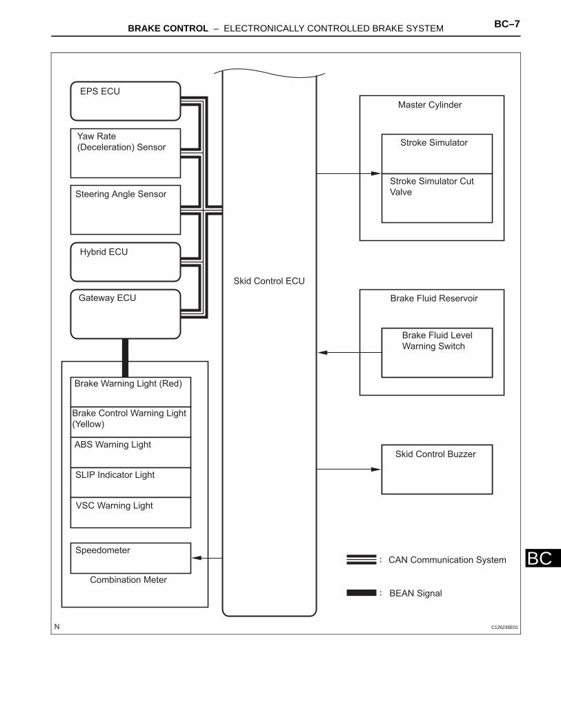
BRAKE CONTROL – ELECTRONICALLY CONTROLLED BRAKE SYSTEM BC–7
BC
:
:
EPS ECU
Yaw Rate
(Deceleration) Sensor
Steering Angle Sensor
Hybrid ECU
Gateway ECU
Skid Control ECU
Master Cylinder
Stroke Simulator
Stroke Simulator Cut
Valve
Brake Fluid Reservoir
Brake Fluid Level
Warning Switch
Skid Control Buzzer
CAN Communication System
BEAN Signal
Brake Warning Light (Red)
Brake Control Warning Light
(Yellow)
ABS Warning Light
SLIP Indicator Light
VSC Warning Light
Speedometer
Combination Meter
C126235E01
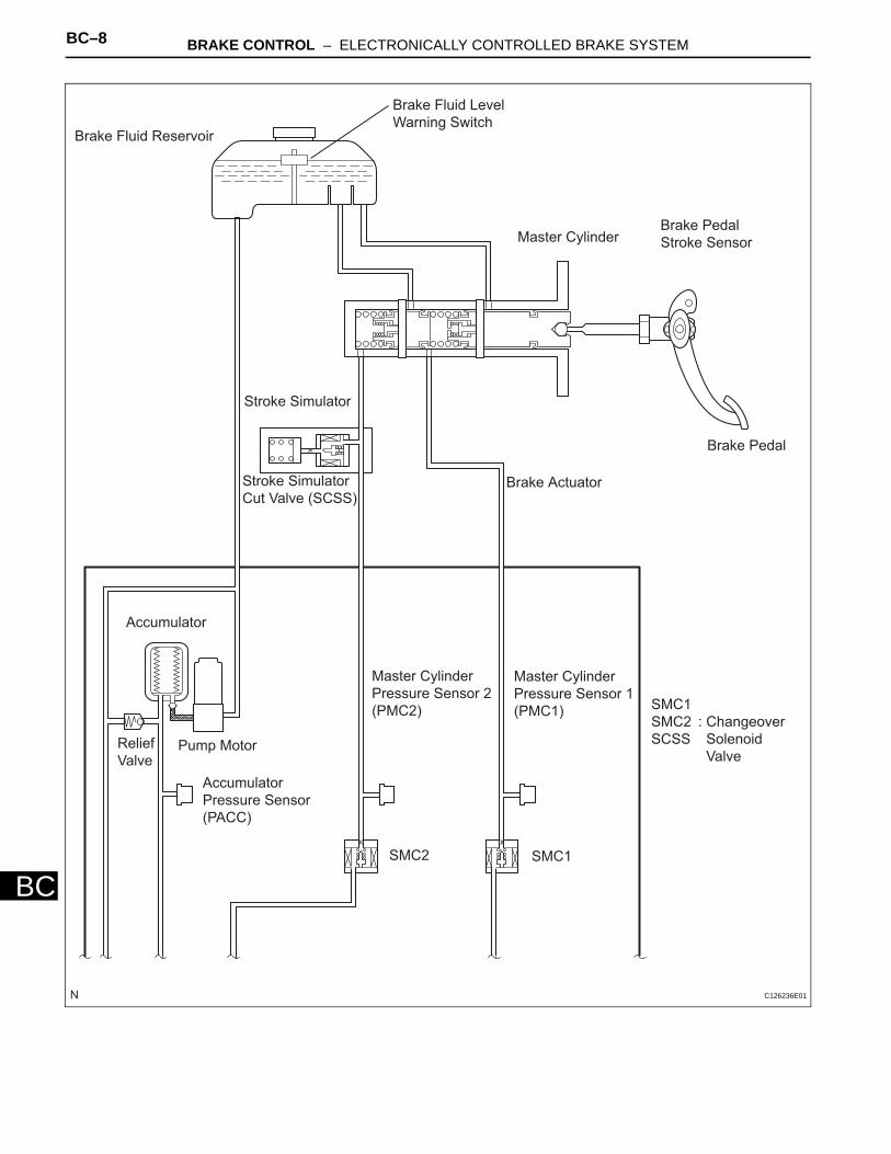
BC–8 BRAKE CONTROL – ELECTRONICALLY CONTROLLED BRAKE SYSTEM
BC
Brake Fluid Reservoir
Brake Fluid Level
Warning Switch
Master CylinderBrake Pedal
Stroke Sensor
Brake Pedal
Brake ActuatorStroke Simulator
Cut Valve (SCSS)
Stroke Simulator
Accumulator
Relief
ValvePump Motor
Accumulator
Pressure Sensor
(PACC)
Master Cylinder
Pressure Sensor 2
(PMC2)
Master Cylinder
Pressure Sensor 1
(PMC1)
SMC2 SMC1
SMC1
SMC2
SCSS
: Changeover
Solenoid
Valve
C126236E01
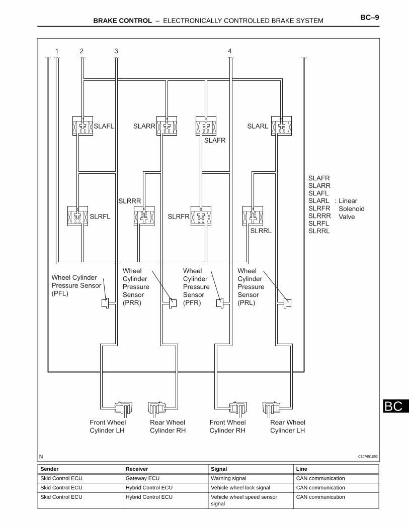
BRAKE CONTROL – ELECTRONICALLY CONTROLLED BRAKE SYSTEM BC–9
BC
Sender Receiver Signal Line
Skid Control ECU Gateway ECU Warning signal CAN communication
Skid Control ECU Hybrid Control ECU Vehicle wheel lock signal CAN communication
Skid Control ECU Hybrid Control ECU Vehicle wheel speed sensor signal
CAN communication
1 2 3 4
SLAFL
SLRFL SLRFR
SLAFR
SLAFR
SLARR
SLRRR
SLARL
SLRRL
SLAFL
SLRFL
SLRFR
SLARR
SLRRR
SLARL
SLRRL
Wheel Cylinder
Pressure Sensor
(PFL)
Front Wheel
Cylinder LH
Rear Wheel
Cylinder RH
Front Wheel
Cylinder RH
Rear Wheel
Cylinder LH
Wheel
Cylinder
Pressure
Sensor
(PRR)
Wheel
Cylinder
Pressure
Sensor
(PFR)
Wheel
Cylinder
Pressure
Sensor
(PRL)
Linear
Solenoid
Valve
:
C107651E02
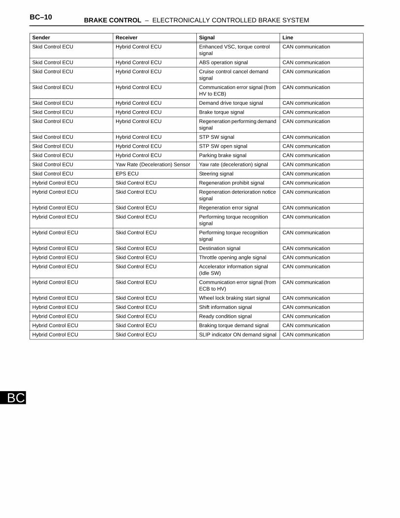
BC–10 BRAKE CONTROL – ELECTRONICALLY CONTROLLED BRAKE SYSTEM
BC
Skid Control ECU Hybrid Control ECU Enhanced VSC, torque control signal
CAN communication
Skid Control ECU Hybrid Control ECU ABS operation signal CAN communication
Skid Control ECU Hybrid Control ECU Cruise control cancel demand signal
CAN communication
Skid Control ECU Hybrid Control ECU Communication error signal (from HV to ECB)
CAN communication
Skid Control ECU Hybrid Control ECU Demand drive torque signal CAN communication
Skid Control ECU Hybrid Control ECU Brake torque signal CAN communication
Skid Control ECU Hybrid Control ECU Regeneration performing demand signal
CAN communication
Skid Control ECU Hybrid Control ECU STP SW signal CAN communication
Skid Control ECU Hybrid Control ECU STP SW open signal CAN communication
Skid Control ECU Hybrid Control ECU Parking brake signal CAN communication
Skid Control ECU Yaw Rate (Deceleration) Sensor Yaw rate (deceleration) signal CAN communication
Skid Control ECU EPS ECU Steering signal CAN communication
Hybrid Control ECU Skid Control ECU Regeneration prohibit signal CAN communication
Hybrid Control ECU Skid Control ECU Regeneration deterioration notice signal
CAN communication
Hybrid Control ECU Skid Control ECU Regeneration error signal CAN communication
Hybrid Control ECU Skid Control ECU Performing torque recognition signal
CAN communication
Hybrid Control ECU Skid Control ECU Performing torque recognition signal
CAN communication
Hybrid Control ECU Skid Control ECU Destination signal CAN communication
Hybrid Control ECU Skid Control ECU Throttle opening angle signal CAN communication
Hybrid Control ECU Skid Control ECU Accelerator information signal (Idle SW)
CAN communication
Hybrid Control ECU Skid Control ECU Communication error signal (from ECB to HV)
CAN communication
Hybrid Control ECU Skid Control ECU Wheel lock braking start signal CAN communication
Hybrid Control ECU Skid Control ECU Shift information signal CAN communication
Hybrid Control ECU Skid Control ECU Ready condition signal CAN communication
Hybrid Control ECU Skid Control ECU Braking torque demand signal CAN communication
Hybrid Control ECU Skid Control ECU SLIP indicator ON demand signal CAN communication
Sender Receiver Signal Line
BRAKE CONTROL – ELECTRONICALLY CONTROLLED BRAKE SYSTEM BC–11
BC
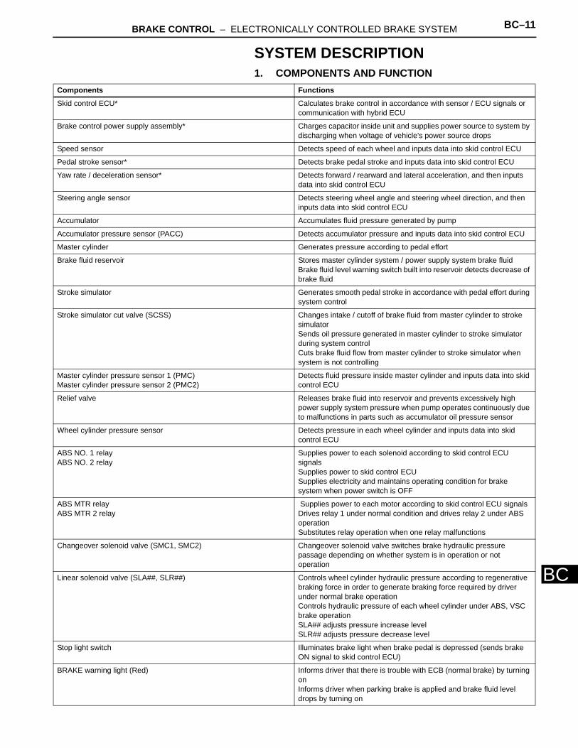
SYSTEM DESCRIPTION1. COMPONENTS AND FUNCTION
Components Functions
Skid control ECU* Calculates brake control in accordance with sensor / ECU signals or communication with hybrid ECU
Brake control power supply assembly* Charges capacitor inside unit and supplies power source to system by discharging when voltage of vehicle's power source drops
Speed sensor Detects speed of each wheel and inputs data into skid control ECU
Pedal stroke sensor* Detects brake pedal stroke and inputs data into skid control ECU
Yaw rate / deceleration sensor* Detects forward / rearward and lateral acceleration, and then inputs data into skid control ECU
Steering angle sensor Detects steering wheel angle and steering wheel direction, and then inputs data into skid control ECU
Accumulator Accumulates fluid pressure generated by pump
Accumulator pressure sensor (PACC) Detects accumulator pressure and inputs data into skid control ECU
Master cylinder Generates pressure according to pedal effort
Brake fluid reservoir Stores master cylinder system / power supply system brake fluidBrake fluid level warning switch built into reservoir detects decrease of brake fluid
Stroke simulator Generates smooth pedal stroke in accordance with pedal effort during system control
Stroke simulator cut valve (SCSS) Changes intake / cutoff of brake fluid from master cylinder to stroke simulatorSends oil pressure generated in master cylinder to stroke simulator during system controlCuts brake fluid flow from master cylinder to stroke simulator when system is not controlling
Master cylinder pressure sensor 1 (PMC)Master cylinder pressure sensor 2 (PMC2)
Detects fluid pressure inside master cylinder and inputs data into skid control ECU
Relief valve Releases brake fluid into reservoir and prevents excessively high power supply system pressure when pump operates continuously due to malfunctions in parts such as accumulator oil pressure sensor
Wheel cylinder pressure sensor Detects pressure in each wheel cylinder and inputs data into skid control ECU
ABS NO. 1 relayABS NO. 2 relay
Supplies power to each solenoid according to skid control ECU signalsSupplies power to skid control ECUSupplies electricity and maintains operating condition for brake system when power switch is OFF
ABS MTR relayABS MTR 2 relay
Supplies power to each motor according to skid control ECU signalsDrives relay 1 under normal condition and drives relay 2 under ABS operationSubstitutes relay operation when one relay malfunctions
Changeover solenoid valve (SMC1, SMC2) Changeover solenoid valve switches brake hydraulic pressure passage depending on whether system is in operation or not operation
Linear solenoid valve (SLA##, SLR##) Controls wheel cylinder hydraulic pressure according to regenerative braking force in order to generate braking force required by driver under normal brake operationControls hydraulic pressure of each wheel cylinder under ABS, VSC brake operationSLA## adjusts pressure increase levelSLR## adjusts pressure decrease level
Stop light switch Illuminates brake light when brake pedal is depressed (sends brake ON signal to skid control ECU)
BRAKE warning light (Red) Informs driver that there is trouble with ECB (normal brake) by turning onInforms driver when parking brake is applied and brake fluid level drops by turning on
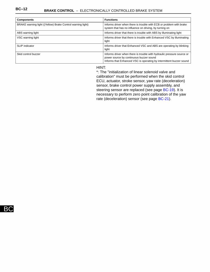
BC–12 BRAKE CONTROL – ELECTRONICALLY CONTROLLED BRAKE SYSTEM
BC
HINT:*: The "initialization of linear solenoid valve and calibration" must be performed when the skid control ECU, actuator, stroke sensor, yaw rate (deceleration) sensor, brake control power supply assembly, and steering sensor are replaced (see page BC-19). It is necessary to perform zero point calibration of the yaw rate (deceleration) sensor (see page BC-21).
BRAKE warning light ((Yellow) Brake Control warning light) Informs driver when there is trouble with ECB or problem with brake system that has no influence on driving, by turning on
ABS warning light Informs driver that there is trouble with ABS by illuminating light
VSC warning light Informs driver that there is trouble with Enhanced VSC by illuminating light
SLIP indicator Informs driver that Enhanced VSC and ABS are operating by blinking light
Skid control buzzer Informs driver when there is trouble with hydraulic pressure source or power source by continuous buzzer soundInforms that Enhanced VSC is operating by intermittent buzzer sound
Components Functions
BRAKE CONTROL – ELECTRONICALLY CONTROLLED BRAKE SYSTEM BC–13
BC
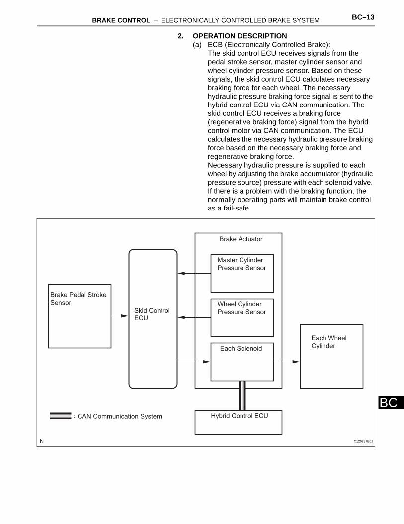
2. OPERATION DESCRIPTION(a) ECB (Electronically Controlled Brake):
The skid control ECU receives signals from the pedal stroke sensor, master cylinder sensor and wheel cylinder pressure sensor. Based on these signals, the skid control ECU calculates necessary braking force for each wheel. The necessary hydraulic pressure braking force signal is sent to the hybrid control ECU via CAN communication. The skid control ECU receives a braking force (regenerative braking force) signal from the hybrid control motor via CAN communication. The ECU calculates the necessary hydraulic pressure braking force based on the necessary braking force and regenerative braking force. Necessary hydraulic pressure is supplied to each wheel by adjusting the brake accumulator (hydraulic pressure source) pressure with each solenoid valve. If there is a problem with the braking function, the normally operating parts will maintain brake control as a fail-safe.
:
Brake Pedal Stroke
Sensor
Skid Control
ECU
Brake Actuator
Master Cylinder
Pressure Sensor
Wheel Cylinder
Pressure Sensor
Each Solenoid
Hybrid Control ECU
Each Wheel
Cylinder
CAN Communication System
C126237E01
BC–14 BRAKE CONTROL – ELECTRONICALLY CONTROLLED BRAKE SYSTEM
BC
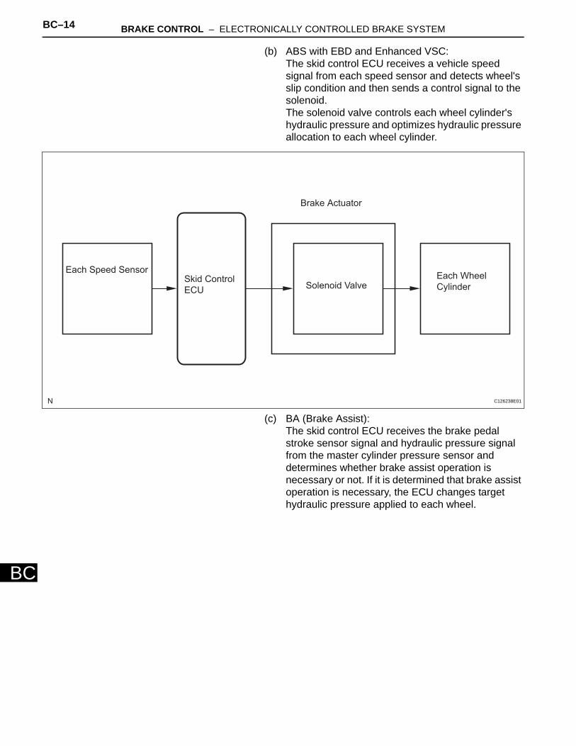
(b) ABS with EBD and Enhanced VSC:The skid control ECU receives a vehicle speed signal from each speed sensor and detects wheel's slip condition and then sends a control signal to the solenoid. The solenoid valve controls each wheel cylinder's hydraulic pressure and optimizes hydraulic pressure allocation to each wheel cylinder.
(c) BA (Brake Assist):The skid control ECU receives the brake pedal stroke sensor signal and hydraulic pressure signal from the master cylinder pressure sensor and determines whether brake assist operation is necessary or not. If it is determined that brake assist operation is necessary, the ECU changes target hydraulic pressure applied to each wheel.
Each Speed SensorSkid Control
ECU
Brake Actuator
Solenoid ValveEach Wheel
Cylinder
C126238E01
BRAKE CONTROL – ELECTRONICALLY CONTROLLED BRAKE SYSTEM BC–15
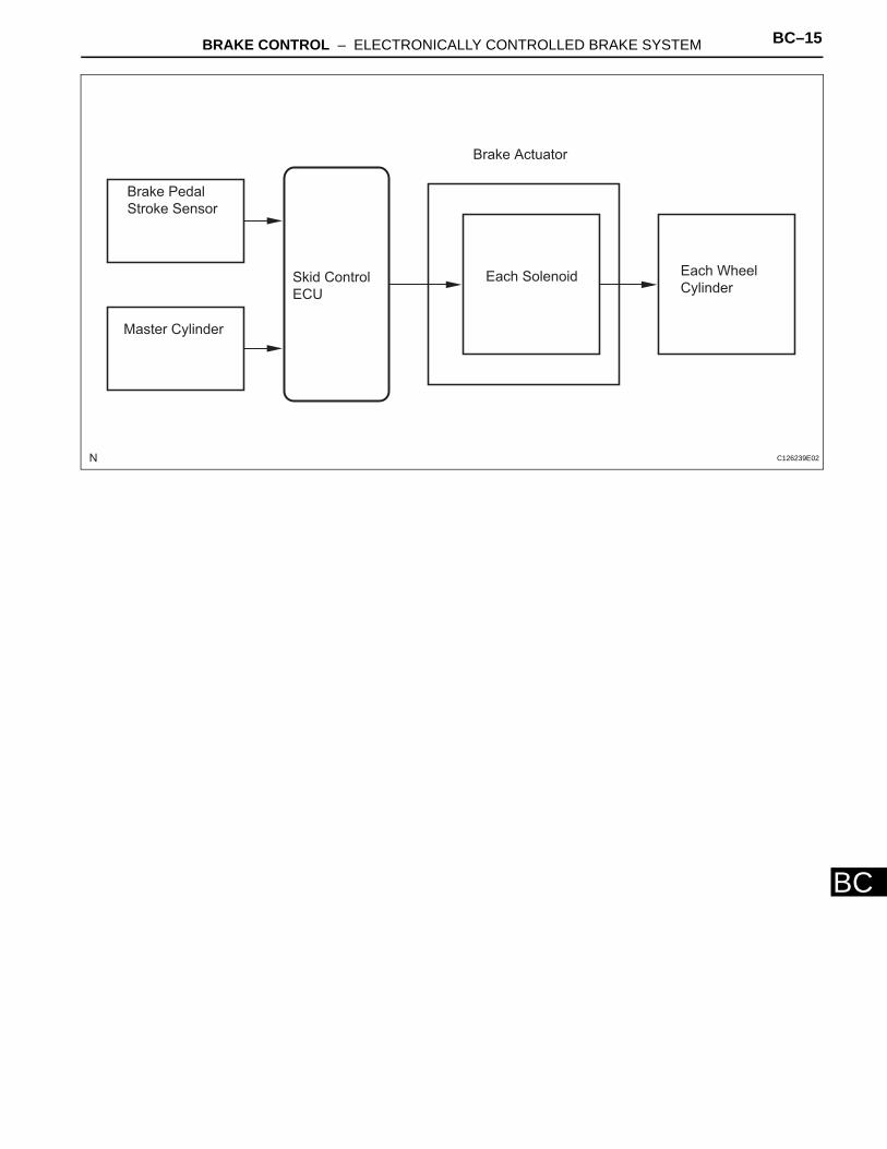
BC
Brake Pedal
Stroke Sensor
Master Cylinder
Skid Control
ECU
Brake Actuator
Each Solenoid Each Wheel
Cylinder
C126239E02
BC–16 BRAKE CONTROL – ELECTRONICALLY CONTROLLED BRAKE SYSTEM
BC
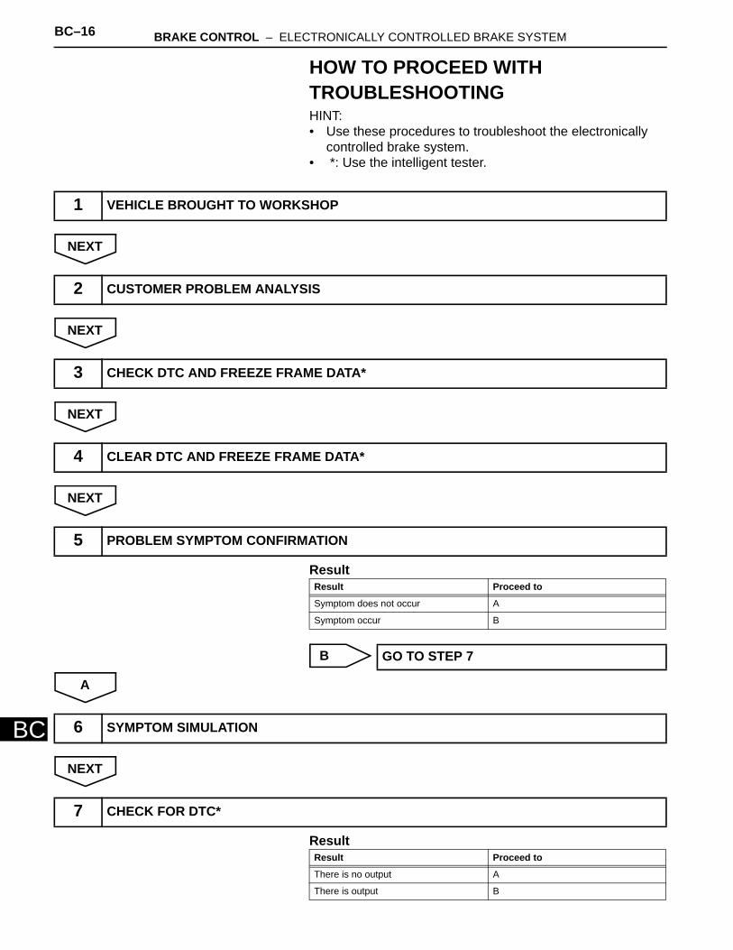
HOW TO PROCEED WITH TROUBLESHOOTINGHINT:• Use these procedures to troubleshoot the electronically
controlled brake system.• *: Use the intelligent tester.
NEXT
NEXT
NEXT
NEXT
Result
B
A
NEXT
Result
1 VEHICLE BROUGHT TO WORKSHOP
2 CUSTOMER PROBLEM ANALYSIS
3 CHECK DTC AND FREEZE FRAME DATA*
4 CLEAR DTC AND FREEZE FRAME DATA*
5 PROBLEM SYMPTOM CONFIRMATION
Result Proceed to
Symptom does not occur A
Symptom occur B
GO TO STEP 7
6 SYMPTOM SIMULATION
7 CHECK FOR DTC*
Result Proceed to
There is no output A
There is output B
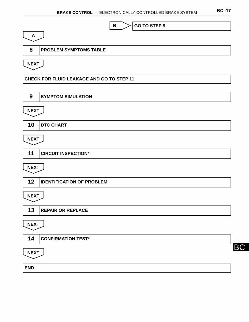
BRAKE CONTROL – ELECTRONICALLY CONTROLLED BRAKE SYSTEM BC–17
BC
B
A
NEXT
NEXT
NEXT
NEXT
NEXT
NEXT
NEXT
GO TO STEP 9
8 PROBLEM SYMPTOMS TABLE
CHECK FOR FLUID LEAKAGE AND GO TO STEP 11
9 SYMPTOM SIMULATION
10 DTC CHART
11 CIRCUIT INSPECTION*
12 IDENTIFICATION OF PROBLEM
13 REPAIR OR REPLACE
14 CONFIRMATION TEST*
END
BC–18 BRAKE CONTROL – ELECTRONICALLY CONTROLLED BRAKE SYSTEM
BC
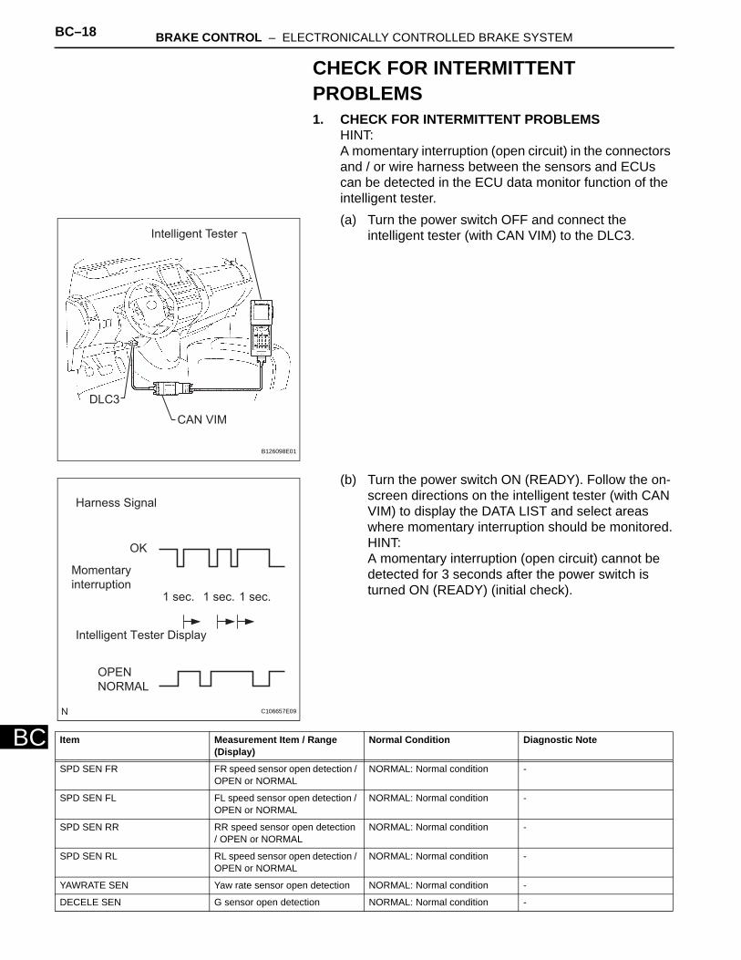
CHECK FOR INTERMITTENT PROBLEMS1. CHECK FOR INTERMITTENT PROBLEMS
HINT:A momentary interruption (open circuit) in the connectors and / or wire harness between the sensors and ECUs can be detected in the ECU data monitor function of the intelligent tester.(a) Turn the power switch OFF and connect the
intelligent tester (with CAN VIM) to the DLC3.
(b) Turn the power switch ON (READY). Follow the on-screen directions on the intelligent tester (with CAN VIM) to display the DATA LIST and select areas where momentary interruption should be monitored.HINT:A momentary interruption (open circuit) cannot be detected for 3 seconds after the power switch is turned ON (READY) (initial check).
DLC3
CAN VIM
Intelligent Tester
B126098E01
1 sec. 1 sec.1 sec.
Harness Signal
Intelligent Tester Display
OK
Momentary
interruption
OPEN
NORMAL
C106657E09
Item Measurement Item / Range (Display)
Normal Condition Diagnostic Note
SPD SEN FR FR speed sensor open detection / OPEN or NORMAL
NORMAL: Normal condition -
SPD SEN FL FL speed sensor open detection / OPEN or NORMAL
NORMAL: Normal condition -
SPD SEN RR RR speed sensor open detection / OPEN or NORMAL
NORMAL: Normal condition -
SPD SEN RL RL speed sensor open detection / OPEN or NORMAL
NORMAL: Normal condition -
YAWRATE SEN Yaw rate sensor open detection NORMAL: Normal condition -
DECELE SEN G sensor open detection NORMAL: Normal condition -
BRAKE CONTROL – ELECTRONICALLY CONTROLLED BRAKE SYSTEM BC–19
BC
HINT:• If the status remains on, check the continuity
between the ECU and the sensors, or between ECUs.
• The OPEN display on the intelligent tester remains on for 1 second after the harness signal changes from momentary interruption (open circuit) to normal condition.
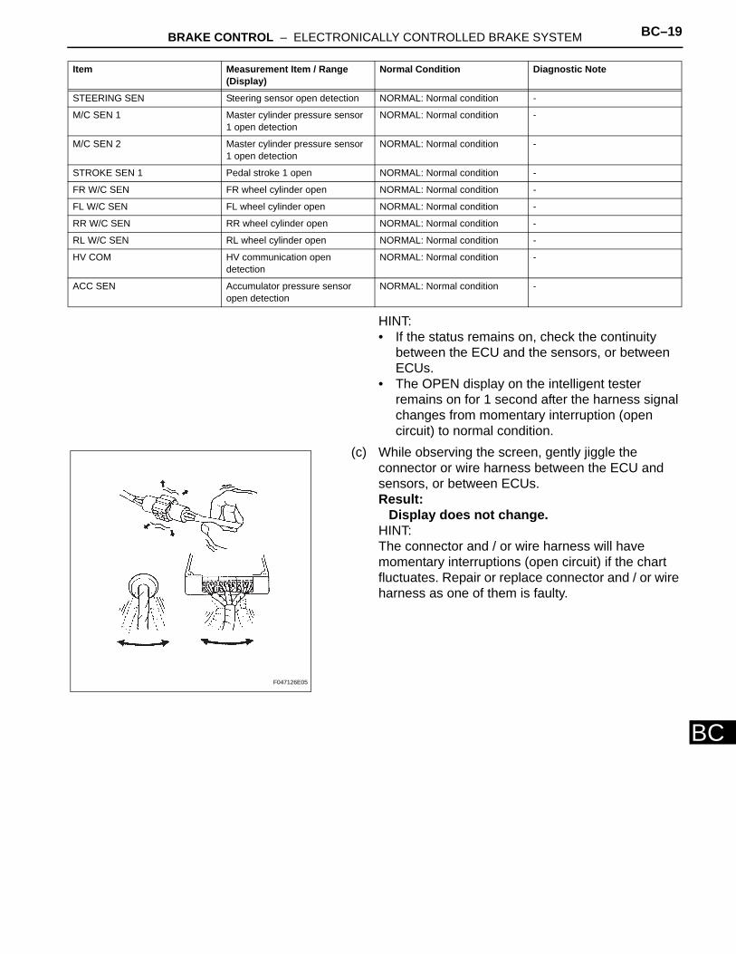
(c) While observing the screen, gently jiggle the connector or wire harness between the ECU and sensors, or between ECUs.Result:
Display does not change.HINT:The connector and / or wire harness will have momentary interruptions (open circuit) if the chart fluctuates. Repair or replace connector and / or wire harness as one of them is faulty.
STEERING SEN Steering sensor open detection NORMAL: Normal condition -
M/C SEN 1 Master cylinder pressure sensor 1 open detection
NORMAL: Normal condition -
M/C SEN 2 Master cylinder pressure sensor 1 open detection
NORMAL: Normal condition -
STROKE SEN 1 Pedal stroke 1 open NORMAL: Normal condition -
FR W/C SEN FR wheel cylinder open NORMAL: Normal condition -
FL W/C SEN FL wheel cylinder open NORMAL: Normal condition -
RR W/C SEN RR wheel cylinder open NORMAL: Normal condition -
RL W/C SEN RL wheel cylinder open NORMAL: Normal condition -
HV COM HV communication open detection
NORMAL: Normal condition -
ACC SEN Accumulator pressure sensor open detection
NORMAL: Normal condition -
Item Measurement Item / Range (Display)
Normal Condition Diagnostic Note
F047126E05
BC–20 BRAKE CONTROL – ELECTRONICALLY CONTROLLED BRAKE SYSTEM
BC
INITIALIZATION1. INITIALIZATION OF LINEAR SOLENOID VALVE AND
CALIBRATIONHINT:• Perform "initialization of linear solenoid valve and
calibration" when the skid control ECU, brake actuator or brake pedal stroke sensor is replaced.
• First perform the pedal stroke sensor zero point calibration and then "initialization of linear solenoid valve and calibration" when the brake stroke sensor is removed / installed or the brake pedal height is adjusted (see page BR-22).
• First bleed air and then perform initialization of linear solenoid valve and calibration when the brake actuator is replaced.
• "Initialization of linear solenoid valve and calibration" cannot be performed again once it is stored unless the data is cleared or damaged. Perform "initialization of linear solenoid valve and calibration" after the stored value is initialized, except when replacing the skid control ECU.
• DTC C1259/59 is stored and ECB control is partly prohibited when the power switch is turned ON (READY) while the service plug grip of the HV battery is removed, preventing "initialization of linear solenoid valve and calibration" from being normally performed. In this case, connect the service plug grip with the power switch OFF and turn the power switch ON (READY) again to cancel the warning (ECB control prohibition).
• If there is a problem with auxiliary battery (12 V) voltage, "initialization of linear solenoid valve and calibration" cannot be completed normally. Make sure to check battery voltage before performing "initialization of linear solenoid valve and calibration".
• If the actuator's temperature is high, "initialization of linear solenoid valve and calibration" may not be completed normally. In that case, wait until the temperature decreases and then perform "initialization of linear solenoid valve and calibration".
• Do not depress the brake pedal during the "initialization of linear solenoid valve and calibration" procedure.
BRAKE CONTROL – ELECTRONICALLY CONTROLLED BRAKE SYSTEM BC–21
BC
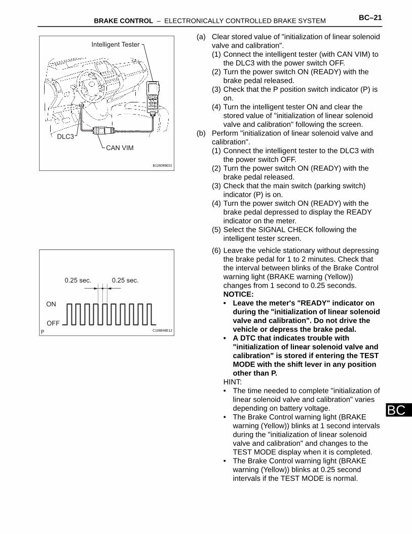
(a) Clear stored value of "initialization of linear solenoid valve and calibration".(1) Connect the intelligent tester (with CAN VIM) to
the DLC3 with the power switch OFF.(2) Turn the power switch ON (READY) with the
brake pedal released.(3) Check that the P position switch indicator (P) is
on.(4) Turn the intelligent tester ON and clear the
stored value of "initialization of linear solenoid valve and calibration" following the screen.
(b) Perform "initialization of linear solenoid valve and calibration".(1) Connect the intelligent tester to the DLC3 with
the power switch OFF.(2) Turn the power switch ON (READY) with the
brake pedal released.(3) Check that the main switch (parking switch)
indicator (P) is on.(4) Turn the power switch ON (READY) with the
brake pedal depressed to display the READY indicator on the meter.
(5) Select the SIGNAL CHECK following the intelligent tester screen.
(6) Leave the vehicle stationary without depressing the brake pedal for 1 to 2 minutes. Check that the interval between blinks of the Brake Control warning light (BRAKE warning (Yellow)) changes from 1 second to 0.25 seconds.NOTICE:• Leave the meter's "READY" indicator on
during the "initialization of linear solenoid valve and calibration". Do not drive the vehicle or depress the brake pedal.
• A DTC that indicates trouble with "initialization of linear solenoid valve and calibration" is stored if entering the TEST MODE with the shift lever in any position other than P.
HINT:• The time needed to complete "initialization of
linear solenoid valve and calibration" varies depending on battery voltage.
• The Brake Control warning light (BRAKE warning (Yellow)) blinks at 1 second intervals during the "initialization of linear solenoid valve and calibration" and changes to the TEST MODE display when it is completed.
• The Brake Control warning light (BRAKE warning (Yellow)) blinks at 0.25 second intervals if the TEST MODE is normal.
DLC3
CAN VIM
Intelligent Tester
B126098E01
0.25 sec. 0.25 sec.
ON
OFFC108848E12
BC–22 BRAKE CONTROL – ELECTRONICALLY CONTROLLED BRAKE SYSTEM
BC
(7) Check that DTC C1346/66 that indicates trouble with stroke sensor zero point learning is not output when the Brake Control warning light changes to the TEST MODE display upon "initialization of linear solenoid valve and calibration" completion.
(8) Enter the NORMAL MODE from the SIGNAL CHECK following the intelligent tester screen.
2. YAW RATE SENSOR / DECELERATION SENSOR INITIALIZATIONHINT:The zero point data of the yaw rate/deceleration sensor stored in the skid control ECU must be cleared when the yaw rate/deceleration sensor is replaced (see page BC-21).
BRAKE CONTROL – ELECTRONICALLY CONTROLLED BRAKE SYSTEM BC–23
BC
CALIBRATION1. DESCRIPTION
(a) Zero point calibration is not performed until the data is cleared when the zero point is once stored. Zero point calibration should be performed after the zero point is cleared if the yaw rate (deceleration) sensor is replaced.
(b) Steering sensor zero point calibration is automatically performed with the vehicle driving straight.
(c) Follow the chart to perform calibration.
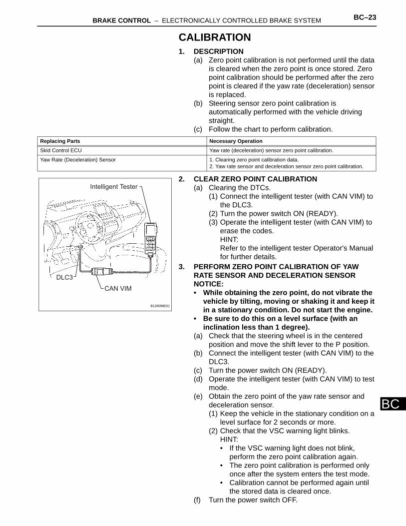
2. CLEAR ZERO POINT CALIBRATION(a) Clearing the DTCs.
(1) Connect the intelligent tester (with CAN VIM) to the DLC3.
(2) Turn the power switch ON (READY).(3) Operate the intelligent tester (with CAN VIM) to
erase the codes.HINT:Refer to the intelligent tester Operator's Manual for further details.
3. PERFORM ZERO POINT CALIBRATION OF YAW RATE SENSOR AND DECELERATION SENSORNOTICE:• While obtaining the zero point, do not vibrate the
vehicle by tilting, moving or shaking it and keep it in a stationary condition. Do not start the engine.
• Be sure to do this on a level surface (with an inclination less than 1 degree).
(a) Check that the steering wheel is in the centered position and move the shift lever to the P position.
(b) Connect the intelligent tester (with CAN VIM) to the DLC3.
(c) Turn the power switch ON (READY).(d) Operate the intelligent tester (with CAN VIM) to test
mode.(e) Obtain the zero point of the yaw rate sensor and
deceleration sensor.(1) Keep the vehicle in the stationary condition on a
level surface for 2 seconds or more.(2) Check that the VSC warning light blinks.
HINT:• If the VSC warning light does not blink,
perform the zero point calibration again.• The zero point calibration is performed only
once after the system enters the test mode.• Calibration cannot be performed again until
the stored data is cleared once.(f) Turn the power switch OFF.
Replacing Parts Necessary Operation
Skid Control ECU Yaw rate (deceleration) sensor zero point calibration.
Yaw Rate (Deceleration) Sensor 1. Clearing zero point calibration data.2. Yaw rate sensor and deceleration sensor zero point calibration.
DLC3
CAN VIM
Intelligent Tester
B126098E01
BC–24 BRAKE CONTROL – ELECTRONICALLY CONTROLLED BRAKE SYSTEM
BC
TEST MODE PROCEDURE1. CHECK WARNING LIGHT AND INDICATOR LIGHT
(a) Release the parking brake pedal.NOTICE:When releasing the parking brake, move the P position switch into the P position to hold the vehicle for safety.HINT:When the parking brake is applied or the level of the brake fluid is low, the BRAKE warning light comes on.
(b) When the power switch is ON (READY), check that the ABS warning light, VSC warning light, BRAKE warning light, Brake Control warning light and SLIP indicator light come on for approximately 3 seconds.HINT:• If the indicator check result is not normal,
proceed to troubleshooting for the ABS warning light circuit, VSC warning light circuit, BRAKE warning light circuit, Brake Control warning light circuit or SLIP indicator light circuit.
• If the indicator remains on, proceed to troubleshooting for the light circuit below.
2. CHECK SENSOR SIGNAL BY TEST MODEHINT:• Set the vehicle in the TEST MODE and perform the
following procedures to check operation of the deceleration sensor, master cylinder pressure sensor, speed sensor and yaw rate sensor.
• Check results are indicated by DTCs output only in the TEST MODE.
• Perform the following procedures (step 1 to step 5) as a set.
• When entering the test mode, the skid control ECU records all the test mode codes and clears the codes judged to be normal.
• During test mode, Enhanced VSC does not operate regardless of whether or not the sensor check result is normal or if there is a malfunction.
• When the mode returns to the normal mode, all the test mode codes are cleared.
• The ABS warning light and VSC warning light comes on if the sensor has a malfunction.
ABS Warning Light BRAKE Warning
Light
USA USA
CANADA CANADA
(Red)
VSC Warning LightSLIP Indicator Light
Brake Control Warning Light
(Yellow)
C126240E01
Trouble Area See procedure
ABS warning light circuit BC-170
VSC warning light circuit BC-171
BRAKE warning light circuit BC-176
Brake Control warning light circuit BC-182
SLIP indicator light circuit BC-187
BRAKE CONTROL – ELECTRONICALLY CONTROLLED BRAKE SYSTEM BC–25
BC
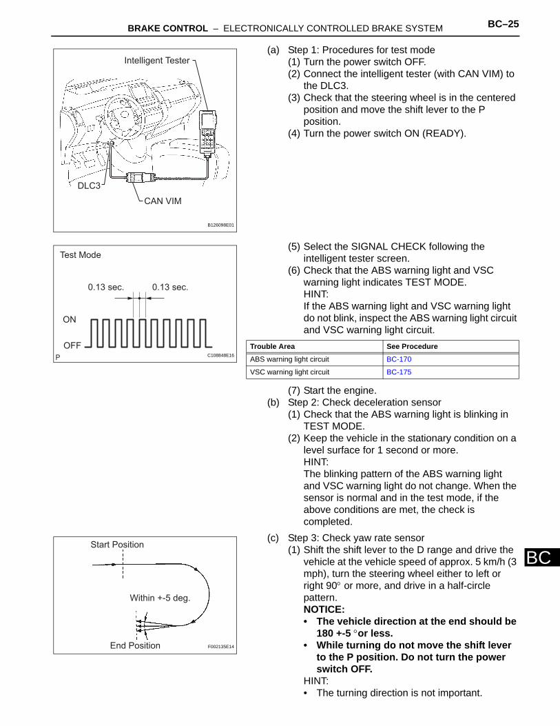
(a) Step 1: Procedures for test mode(1) Turn the power switch OFF.(2) Connect the intelligent tester (with CAN VIM) to
the DLC3.(3) Check that the steering wheel is in the centered
position and move the shift lever to the P position.
(4) Turn the power switch ON (READY).
(5) Select the SIGNAL CHECK following the intelligent tester screen.
(6) Check that the ABS warning light and VSC warning light indicates TEST MODE.HINT:If the ABS warning light and VSC warning light do not blink, inspect the ABS warning light circuit and VSC warning light circuit.
(7) Start the engine.(b) Step 2: Check deceleration sensor
(1) Check that the ABS warning light is blinking in TEST MODE.
(2) Keep the vehicle in the stationary condition on a level surface for 1 second or more.HINT:The blinking pattern of the ABS warning light and VSC warning light do not change. When the sensor is normal and in the test mode, if the above conditions are met, the check is completed.
(c) Step 3: Check yaw rate sensor(1) Shift the shift lever to the D range and drive the
vehicle at the vehicle speed of approx. 5 km/h (3 mph), turn the steering wheel either to left or right 90° or more, and drive in a half-circle pattern.NOTICE:• The vehicle direction at the end should be
180 +-5 °or less.• While turning do not move the shift lever
to the P position. Do not turn the power switch OFF.
HINT:• The turning direction is not important.
DLC3
CAN VIM
Intelligent Tester
B126098E01
Test Mode
0.13 sec. 0.13 sec.
ON
OFFC108848E16
Trouble Area See Procedure
ABS warning light circuit BC-170
VSC warning light circuit BC-175
Start Position
End Position
Within +-5 deg.
F002135E14
BC–26 BRAKE CONTROL – ELECTRONICALLY CONTROLLED BRAKE SYSTEM
BC
• Turning should be completed within 2.0 seconds. However, it is possible to change the vehicle speed, stop or more backward.
(2) Stop the vehicle and move the shift lever to the P position, check that the skid control buzzer sounds for 3 seconds.HINT:• If the skid control buzzer sounds, the sensor
check is completed normally.• If the skid control buzzer does not sound,
check the skid control buzzer circuit (see page BC-191), then perform the sensor check again.
• If the skid control buzzer still will not sound, there is a malfunction in the Enhanced VSC sensor, so check the DTC.
• Drive the vehicle in a half-circle pattern. At the end of the turn, the direction of the vehicle should be within 180 +-5° of its start position.
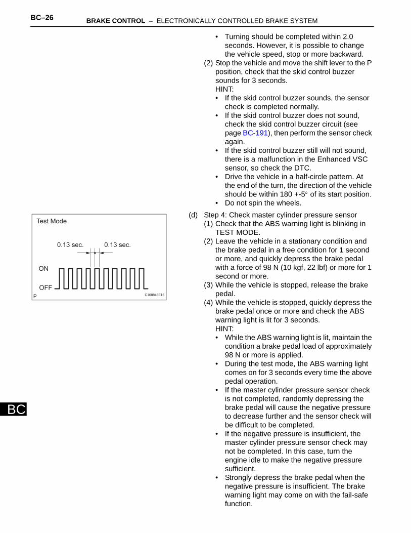
• Do not spin the wheels.(d) Step 4: Check master cylinder pressure sensor
(1) Check that the ABS warning light is blinking in TEST MODE.
(2) Leave the vehicle in a stationary condition and the brake pedal in a free condition for 1 second or more, and quickly depress the brake pedal with a force of 98 N (10 kgf, 22 lbf) or more for 1 second or more.
(3) While the vehicle is stopped, release the brake pedal.
(4) While the vehicle is stopped, quickly depress the brake pedal once or more and check the ABS warning light is lit for 3 seconds.HINT:• While the ABS warning light is lit, maintain the
condition a brake pedal load of approximately 98 N or more is applied.
• During the test mode, the ABS warning light comes on for 3 seconds every time the above pedal operation.
• If the master cylinder pressure sensor check is not completed, randomly depressing the brake pedal will cause the negative pressure to decrease further and the sensor check will be difficult to be completed.
• If the negative pressure is insufficient, the master cylinder pressure sensor check may not be completed. In this case, turn the engine idle to make the negative pressure sufficient.
• Strongly depress the brake pedal when the negative pressure is insufficient. The brake warning light may come on with the fail-safe function.
Test Mode
0.13 sec. 0.13 sec.
ON
OFFC108848E16
BRAKE CONTROL – ELECTRONICALLY CONTROLLED BRAKE SYSTEM BC–27
BC
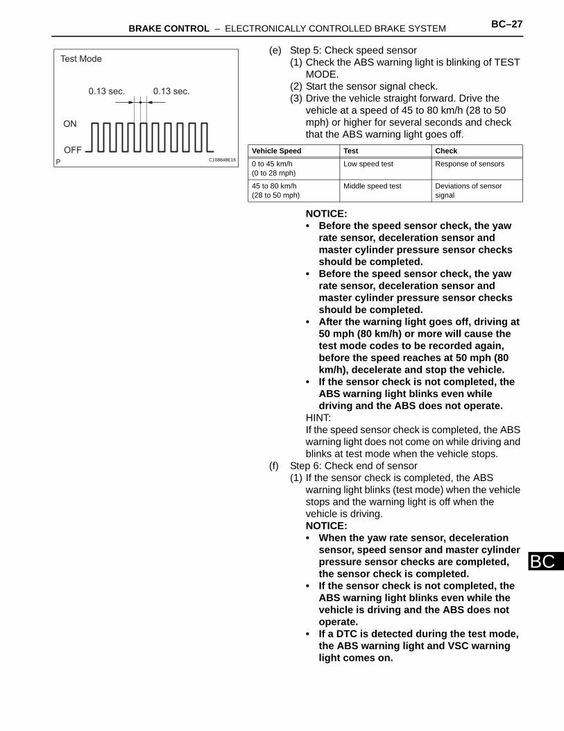
(e) Step 5: Check speed sensor(1) Check the ABS warning light is blinking of TEST
MODE.(2) Start the sensor signal check.(3) Drive the vehicle straight forward. Drive the
vehicle at a speed of 45 to 80 km/h (28 to 50 mph) or higher for several seconds and check that the ABS warning light goes off.
NOTICE:• Before the speed sensor check, the yaw
rate sensor, deceleration sensor and master cylinder pressure sensor checks should be completed.
• Before the speed sensor check, the yaw rate sensor, deceleration sensor and master cylinder pressure sensor checks should be completed.
• After the warning light goes off, driving at 50 mph (80 km/h) or more will cause the test mode codes to be recorded again, before the speed reaches at 50 mph (80 km/h), decelerate and stop the vehicle.
• If the sensor check is not completed, the ABS warning light blinks even while driving and the ABS does not operate.
HINT:If the speed sensor check is completed, the ABS warning light does not come on while driving and blinks at test mode when the vehicle stops.
(f) Step 6: Check end of sensor(1) If the sensor check is completed, the ABS
warning light blinks (test mode) when the vehicle stops and the warning light is off when the vehicle is driving.NOTICE:• When the yaw rate sensor, deceleration
sensor, speed sensor and master cylinder pressure sensor checks are completed, the sensor check is completed.
• If the sensor check is not completed, the ABS warning light blinks even while the vehicle is driving and the ABS does not operate.
• If a DTC is detected during the test mode, the ABS warning light and VSC warning light comes on.
Test Mode
0.13 sec. 0.13 sec.
ON
OFFC108848E16
Vehicle Speed Test Check
0 to 45 km/h(0 to 28 mph)
Low speed test Response of sensors
45 to 80 km/h(28 to 50 mph)
Middle speed test Deviations of sensor signal
BC–28 BRAKE CONTROL – ELECTRONICALLY CONTROLLED BRAKE SYSTEM
BC
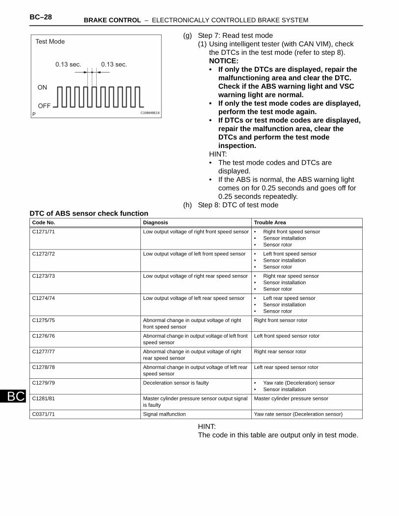
(g) Step 7: Read test mode(1) Using intelligent tester (with CAN VIM), check
the DTCs in the test mode (refer to step 8).NOTICE:• If only the DTCs are displayed, repair the
malfunctioning area and clear the DTC. Check if the ABS warning light and VSC warning light are normal.
• If only the test mode codes are displayed, perform the test mode again.
• If DTCs or test mode codes are displayed, repair the malfunction area, clear the DTCs and perform the test mode inspection.
HINT:• The test mode codes and DTCs are
displayed.• If the ABS is normal, the ABS warning light
comes on for 0.25 seconds and goes off for 0.25 seconds repeatedly.
(h) Step 8: DTC of test modeDTC of ABS sensor check function
HINT:The code in this table are output only in test mode.
Test Mode
0.13 sec. 0.13 sec.
ON
OFFC108848E16
Code No. Diagnosis Trouble Area
C1271/71 Low output voltage of right front speed sensor • Right front speed sensor • Sensor installation• Sensor rotor
C1272/72 Low output voltage of left front speed sensor • Left front speed sensor• Sensor installation• Sensor rotor
C1273/73 Low output voltage of right rear speed sensor • Right rear speed sensor• Sensor installation • Sensor rotor
C1274/74 Low output voltage of left rear speed sensor • Left rear speed sensor• Sensor installation• Sensor rotor
C1275/75 Abnormal change in output voltage of right front speed sensor
Right front sensor rotor
C1276/76 Abnormal change in output voltage of left front speed sensor
Left front speed sensor rotor
C1277/77 Abnormal change in output voltage of right rear speed sensor
Right rear sensor rotor
C1278/78 Abnormal change in output voltage of left rear speed sensor
Left rear speed sensor rotor
C1279/79 Deceleration sensor is faulty • Yaw rate (Deceleration) sensor• Sensor installation
C1281/81 Master cylinder pressure sensor output signal is faulty
Master cylinder pressure sensor
C0371/71 Signal malfunction Yaw rate sensor (Deceleration sensor)
BRAKE CONTROL – ELECTRONICALLY CONTROLLED BRAKE SYSTEM BC–29
BC
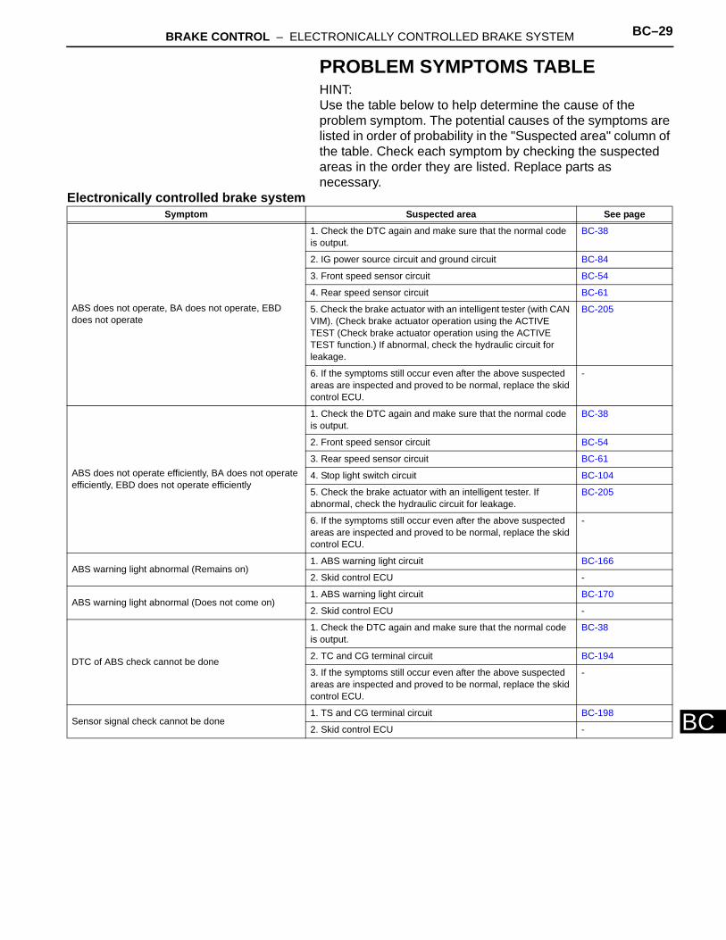
PROBLEM SYMPTOMS TABLEHINT:Use the table below to help determine the cause of the problem symptom. The potential causes of the symptoms are listed in order of probability in the "Suspected area" column of the table. Check each symptom by checking the suspected areas in the order they are listed. Replace parts as necessary.
Electronically controlled brake systemSymptom Suspected area See page
ABS does not operate, BA does not operate, EBD does not operate
1. Check the DTC again and make sure that the normal code is output.
BC-38
2. IG power source circuit and ground circuit BC-84
3. Front speed sensor circuit BC-54
4. Rear speed sensor circuit BC-61
5. Check the brake actuator with an intelligent tester (with CAN VIM). (Check brake actuator operation using the ACTIVE TEST (Check brake actuator operation using the ACTIVE TEST function.) If abnormal, check the hydraulic circuit for leakage.
BC-205
6. If the symptoms still occur even after the above suspected areas are inspected and proved to be normal, replace the skid control ECU.
-
ABS does not operate efficiently, BA does not operate efficiently, EBD does not operate efficiently
1. Check the DTC again and make sure that the normal code is output.
BC-38
2. Front speed sensor circuit BC-54
3. Rear speed sensor circuit BC-61
4. Stop light switch circuit BC-104
5. Check the brake actuator with an intelligent tester. If abnormal, check the hydraulic circuit for leakage.
BC-205
6. If the symptoms still occur even after the above suspected areas are inspected and proved to be normal, replace the skid control ECU.
-
ABS warning light abnormal (Remains on)1. ABS warning light circuit BC-166
2. Skid control ECU -
ABS warning light abnormal (Does not come on)1. ABS warning light circuit BC-170
2. Skid control ECU -
DTC of ABS check cannot be done
1. Check the DTC again and make sure that the normal code is output.
BC-38
2. TC and CG terminal circuit BC-194
3. If the symptoms still occur even after the above suspected areas are inspected and proved to be normal, replace the skid control ECU.
-
Sensor signal check cannot be done1. TS and CG terminal circuit BC-198
2. Skid control ECU -
BC–30 BRAKE CONTROL – ELECTRONICALLY CONTROLLED BRAKE SYSTEM
BC
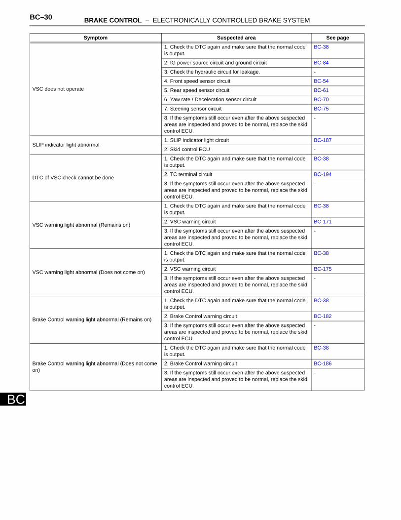
VSC does not operate
1. Check the DTC again and make sure that the normal code is output.
BC-38
2. IG power source circuit and ground circuit BC-84
3. Check the hydraulic circuit for leakage. -
4. Front speed sensor circuit BC-54
5. Rear speed sensor circuit BC-61
6. Yaw rate / Deceleration sensor circuit BC-70
7. Steering sensor circuit BC-75
8. If the symptoms still occur even after the above suspected areas are inspected and proved to be normal, replace the skid control ECU.
-
SLIP indicator light abnormal1. SLIP indicator light circuit BC-187
2. Skid control ECU -
DTC of VSC check cannot be done
1. Check the DTC again and make sure that the normal code is output.
BC-38
2. TC terminal circuit BC-194
3. If the symptoms still occur even after the above suspected areas are inspected and proved to be normal, replace the skid control ECU.
-
VSC warning light abnormal (Remains on)
1. Check the DTC again and make sure that the normal code is output.
BC-38
2. VSC warning circuit BC-171
3. If the symptoms still occur even after the above suspected areas are inspected and proved to be normal, replace the skid control ECU.
-
VSC warning light abnormal (Does not come on)
1. Check the DTC again and make sure that the normal code is output.
BC-38
2. VSC warning circuit BC-175
3. If the symptoms still occur even after the above suspected areas are inspected and proved to be normal, replace the skid control ECU.
-
Brake Control warning light abnormal (Remains on)
1. Check the DTC again and make sure that the normal code is output.
BC-38
2. Brake Control warning circuit BC-182
3. If the symptoms still occur even after the above suspected areas are inspected and proved to be normal, replace the skid control ECU.
-
Brake Control warning light abnormal (Does not come on)
1. Check the DTC again and make sure that the normal code is output.
BC-38
2. Brake Control warning circuit BC-186
3. If the symptoms still occur even after the above suspected areas are inspected and proved to be normal, replace the skid control ECU.
-
Symptom Suspected area See page
BRAKE CONTROL – ELECTRONICALLY CONTROLLED BRAKE SYSTEM BC–31
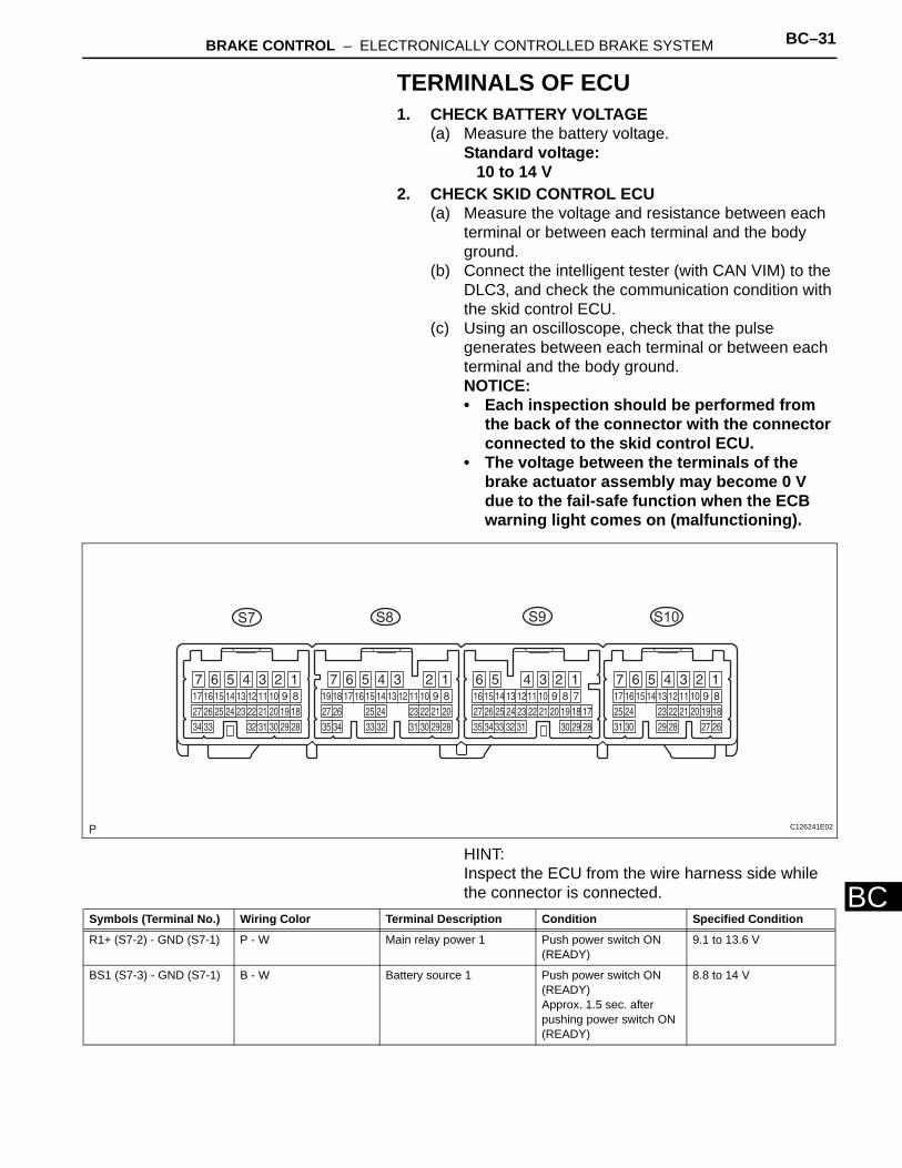
BC
TERMINALS OF ECU1. CHECK BATTERY VOLTAGE
(a) Measure the battery voltage.Standard voltage:
10 to 14 V2. CHECK SKID CONTROL ECU
(a) Measure the voltage and resistance between each terminal or between each terminal and the body ground.
(b) Connect the intelligent tester (with CAN VIM) to the DLC3, and check the communication condition with the skid control ECU.
(c) Using an oscilloscope, check that the pulse generates between each terminal or between each terminal and the body ground.NOTICE:• Each inspection should be performed from
the back of the connector with the connector connected to the skid control ECU.
• The voltage between the terminals of the brake actuator assembly may become 0 V due to the fail-safe function when the ECB warning light comes on (malfunctioning).
HINT:Inspect the ECU from the wire harness side while the connector is connected.
S7 S9 S10S8
C126241E02
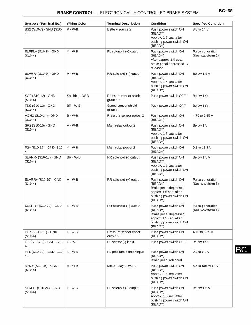
Symbols (Terminal No.) Wiring Color Terminal Description Condition Specified Condition
R1+ (S7-2) - GND (S7-1) P - W Main relay power 1 Push power switch ON (READY)
9.1 to 13.6 V
BS1 (S7-3) - GND (S7-1) B - W Battery source 1 Push power switch ON (READY)Approx. 1.5 sec. after pushing power switch ON (READY)
8.8 to 14 V
BC–32 BRAKE CONTROL – ELECTRONICALLY CONTROLLED BRAKE SYSTEM
BC
SMC1 (S7-4) - GND (S7-1)
Y - W Master cut solenoid 1 output
Push power switch ON (READY)Brake pedal depressed approx. 1.5 sec. after pushing power switch ON (READY)
Below 1.5 V
+BCTY (S7-5) - GND (S7-1)
V - W Courtesy power input Driver door open → close Approx. 5 sec. 8 to 16 V → Below 1 V
SLAFR- (S7-6) - GND (S7-1)
W - W FR solenoid (-) output Push power switch ON (READY)Approx. 1.5 sec. after pushing power switch ON (READY)
Below 1.5 V
SLAFR+ (S7-7) - GND (S7-1)
R - W FR solenoid (+) output Push power switch ON (READY)Brake pedal depressed approx. 1.5 sec. after pushing power switch ON (READY)
Pulse generation (see waveform 1)
E (S7-8) - GND (S7-1) L - W Pressure sensor ground Push power switch OFF Below 1 Ω
VCM1 (S7-9) - GND (S7-1)
P - W Pressure sensor power Push power switch ON (READY)
4.75 to 5.25 V
MR1+ (S7-11) - GND (S7-1)
GR - W Motor relay power 1 Push power switch ON (READY)Approx. 1.5 sec. after pushing power switch ON (READY)
8.8 to 14 V
SR1 (S7-12) - GND (S7-1) L - W Main relay output 1 Push power switch ON (READY)Approx. 1.5 sec. or more after pushing power switch ON (READY)
Below 1 V
SCSS (S7-13) - GND (S7-1)
BR - W Stroke simulator cut solenoid output
Push power switch ON (READY)Brake pedal depressed
Below 1.5 V
SLARL+ (S7-15) - GND (S7-1)
L - W RL solenoid (+) output Push power switch ON (READY)Brake pedal depressed approx. 1.5 sec. after pushing power switch ON (READY)
Pulse generation(see waveform 1)
SLRRL+ (S7-16) - GND (S7-1)
W - W RL solenoid (+) output Push power switch ON (READY)Brake pedal depressed approx. 1.5 sec. after pushing power switch ON (READY)
Pulse generation(see waveform 1)
SLRFR+ (S7-17) - GND (S7-1)
Y - W FR solenoid (+) output Push power switch ON (READY)After approx. 1.5 sec., brake pedal depressed → released
Pulse generation(see waveform 2)
PRL (S7-18) - GND (S7-1) G - W RL pressure sensor input Push power switch ON (READY)Brake pedal released
0.3 to 0.8 V
SG1 (S7-20) - GND (S7-1) BR - W Pressure sensor shield ground 1
Push power switch OFF Below 1 Ω
PACC (S7-21) - GND (S7-1)
W - W Accumulator pressure sensor input
Push power switch ON (READY)After pump motor operates and stops by pedal operation
3.3 to 4.7 V
FR- (S7-22) - GND (S7-1) L - W FR sensor (-) input Push power switch OFF Below 1 Ω
Symbols (Terminal No.) Wiring Color Terminal Description Condition Specified Condition
BRAKE CONTROL – ELECTRONICALLY CONTROLLED BRAKE SYSTEM BC–33
BC
PFR (S7-23) - GND (S7-1) Y - W FR pressure sensor input Push power switch ON (READY)Brake pedal released
0.3 to 0.8 V
MR1 (S7-25) - GND (S7-1) L - W Motor relay output 1 Push power switch ON (READY)Pump motor is operating
Below 1.5 V
SLRRL- (S7-26) - GND (S7-1)
P - W RL solenoid (-) output Push power switch ON (READY)Approx. 1.5 sec. after pushing power switch ON (READY)
Below 1.5 V
SLARL- (S7-27) - GND (S7-1)
LG - W RL solenoid (-) output Push power switch ON (READY)Approx. 1.5 sec. after pushing power switch ON (READY)
Below 1.5 V
MTT (S7-29) - GND (S7-1) R - W Motor test input Push power switch ON (READY)Pump motor is operating
3.5 V or higher
PMC1 (S7-30) - GND (S7-1)
R - W Master pressure sensor input 1
Push power switch ON (READY)Brake pedal released
0.3 to 0.8 V
PCK1 (S7-31) - GND (S7-1)
B - W Pressure sensor check output 1
Push power switch ON (READY)Approx. 1.5 sec. after pushing power switch ON (READY)
4.75 to 5.25 V
FR+ (S7-32) - GND (S7-1) P - W FR sensor (+) input Vehicle speed input Pulse generation (see waveform 3)
SLRFR- (S7-34) - GND (S7-1)
B - W FR solenoid (-) output Push power switch ON (READY)Approx. 1.5 sec. after pushing power switch ON (READY)
Below 1.5 V
+BI1 (S8-3) - GND (S8-1, 2)
B - W Main relay power input 1 Push power switch OFF 10 to 14 V
+BO1 (S8-5) - GND (S8-1, 2)
Y - W Main relay power output 1 Push power switch ON (IG)
8.8 to 14 V
IG1 (S8-7) - GND (S8-1, 2)
B - W IG1 power Push power switch ON (IG)
10 to 14 V
RSS (S8-10) - GND (S8-1, 2)
BR - W Speed sensor shield ground
Push power switch OFF Below 1 Ω
BZ (S8-12) - GND (S8-1, 2)
BR - W Warning buzzer output Push power switch ON (READY)Buzzer is operating
Below 1 V
STP (S8-14) - GND (S8-1, 2)
R - W Stop light switch signal input
Push power switch ON (READY)Brake pedal depressed → released
8 to 14 V → Below 1 V
CAN-L (S8-18) - GND (S8-1, 2)
W - W CAN communication(Send and receive-)
Check DTC using intelligent tester
CAN communication's DTC is not output
CAN-H (S8-19) - GND (S8-1, 2)
B - W CAN communication(Send and receive+)
Check DTC using intelligent tester
CAN communication's DTC is not output
FAIL (S8-20) - GND (S8-1, 2)
P - W Capacitor communication(Receive)
Push power switch ON (READY)Approx. 1.5 sec. after pushing power switch ON (READY)
Pulse generation(See waveform 5)
SP1 (S8-22) - GND (S8-1, 2)
V - W Speed meter output Vehicle speed input Pulse generation(See waveform 4)
Symbols (Terminal No.) Wiring Color Terminal Description Condition Specified Condition
BC–34 BRAKE CONTROL – ELECTRONICALLY CONTROLLED BRAKE SYSTEM
BC
RL- (S8-27) - GND (S8-1, 2)
B - W RL sensor (-) input Push power switch OFF Below 1 Ω
D/G (S8-28) - GND (S8-1, 2)
W - W Diagnosis output Push power switch ON (READY)
9.1 to 13.6 V
ENA (S8-30) - GND (S8-1, 2)
B - W Capacitor communication(Send)
Push power switch ON (READY)Approx. 1.5 sec. after pushing power switch ON (READY)
Pulse generation(See waveform 6)
TS (S8-32) - GND (S8-1, 2)
L - W Sensor diagnosis check input
Push power switch ON (READY)
Below 1.5 V → 9.1 to 13.6 V
VBZ (S8-33) - GND (S8-1, 2)
B - W Warning buzzer power Push power switch ON (READY)
9.1 to 13.6 V
RL+ (S8-35) - GND (S8-1, 2)
W - W RL sensor (+) input Vehicle speed input Pulse generation(See waveform 3)
+BO2 (S9-4) - GND (S9-1, 2)
W - W-B Main relay power output 2 Push power switch ON (READY)
8.8 to 14 V
+BI2 (S9-5) - GND (S9-1, 2)
R - W-B Main relay power input 2 Push power switch OFF 10 to 14 V
VCSK (S9-6) - GND (S9-1, 2)
B - W-B Stroke sensor power Push power switch ON (READY)
3.75 to 4.95 V
SSK (S9-7) - GND (S9-1, 2)
Shielded - W-B Stroke sensor shield ground
Push power switch OFF Below 1 Ω
SKG (S9-8) - GND (S9-1, 2)
W - W-B Stroke sensor ground Push power switch OFF Below 1 Ω
PKB (S9-14) - GND (S9-1, 2)
R - W-B Parking brake signal input Parking brake applied → released
Below 1.5 V → 9.1 to 13.6 V
SKS1 (S9-21) - GND (S9-1, 2)
R - W-B Stroke sensor signal input 1 Push power switch ON (READY)Brake pedal released
0.46 to 1.35 V
SKS2 (S9-22) - GND (S9-1, 2)
G - W-B Stroke sensor signal input 2 Push power switch ON (READY) Brake pedal released
2.56 to 4.35 V
RR- (S9-23) - GND (S9-1, 2)
B - W-B RR sensor (-) input Push power switch OFF Below 1 Ω
RR+ (S9-31) - GND (S9-1, 2)
W - W-B RR sensor (+) input Vehicle speed input Pulse generation(See waveform 3)
SLAFL+ (S10-1) - GND (S10-4)
P - W-B FL solenoid (+) output Push power switch ON (READY)Brake pedal depressed approx. 1.5 sec. after pushing power switch ON (READY)
Pulse generation(See waveform 1)
SLAFL- (S10-2) - GND (S10-4)
O - W-B FL solenoid (-) output Push power switch ON (READY)Approx. 1.5 sec. after pushing power switch ON (READY)
Below 1.5 V
SMC2 (S10-3) - GND (S10-4)
LG - W-B Master cut solenoid 2 output
Push power switch ON (READY)Brake pedal depressed approx. 1.5 sec. after pushing power switch ON (READY)
Below 1.5 V
IG2 (S10-5) - GND (S10-4)
O - W-B IG2 power Push power switch ON (READY)
10 to 14 V
LBL (S10-6) - GND (S10-4)
P - W-B Brake fluid level switch input
Reservoir level switch OFF → ON
4 to 4.65 V→ Below 1.5 V
Symbols (Terminal No.) Wiring Color Terminal Description Condition Specified Condition
BRAKE CONTROL – ELECTRONICALLY CONTROLLED BRAKE SYSTEM BC–35
BC
BS2 (S10-7) - GND (S10-4)
P - W-B Battery source 2 Push power switch ON (READY)Approx. 1.5 sec. after pushing power switch ON (READY)
8.8 to 14 V
SLRFL+ (S10-8) - GND (S10-4)
Y - W-B FL solenoid (+) output Push power switch ON (READY)After approx. 1.5 sec., brake pedal depressed → released
Pulse generation(See waveform 2)
SLARR- (S10-9) - GND (S10-4)
P - W-B RR solenoid (- ) output Push power switch ON (READY)Approx. 1.5 sec. after pushing power switch ON (READY)
Below 1.5 V
SG2 (S10-12) - GND (S10-4)
Shielded - W-B Pressure sensor shield ground 2
Push power switch OFF Below 1 Ω
FSS (S10-13) - GND (S10-4)
BR - W-B Speed sensor shield ground
Push power switch OFF Below 1 Ω
VCM2 (S10-14) - GND (S10-4)
B - W-B Pressure sensor power 2 Push power switch ON (READY)
4.75 to 5.25 V
SR2 (S10-15) - GND (S10-4)
V - W-B Main relay output 2 Push power switch ON (READY)Approx. 1.5 sec. after pushing power switch ON (READY)
Below 1 V
R2+ (S10-17) - GND (S10-4)
Y - W-B Main relay power 2 Push power switch ON (READY)
9.1 to 13.6 V
SLRRR- (S10-18) - GND (S10-4)
BR - W-B RR solenoid (-) output Push power switch ON (READY)Approx. 1.5 sec. after pushing power switch ON (READY)
Below 1.5 V
SLARR+ (S10-19) - GND (S10-4)
V - W-B RR solenoid (+) output Push power switch ON (READY)Brake pedal depressed approx. 1.5 sec. after pushing power switch ON (READY)
Pulse generation(See waveform 1)
SLRRR+ (S10-20) - GND (S10-4)
R - W-B RR solenoid (+) output Push power switch ON (READY)Brake pedal depressed approx. 1.5 sec. after pushing power switch ON (READY)
Pulse generation(See waveform 1)
PCK2 (S10-21) - GND (S10-4)
L - W-B Pressure sensor check output 2
Push power switch ON (READY)
4.75 to 5.25 V
FL- (S10-22 ) - GND (S10-4)
G - W-B FL sensor (-) input Push power switch OFF Below 1 Ω
PFL (S10-23) - GND (S10-4)
R - W-B FL pressure sensor input Push power switch ON (READY)Brake pedal released
0.3 to 0.8 V
MR2+ (S10-25) - GND (S10-4)
R - W-B Motor relay power 2 Push power switch ON (READY)Approx. 1.5 sec. after pushing power switch ON (READY)
8.8 to Below 14 V
SLRFL- (S10-26) - GND (S10-4)
L - W-B FL solenoid (-) output Push power switch ON (READY)Approx. 1.5 sec. after pushing power switch ON (READY)
Below 1.5 V
Symbols (Terminal No.) Wiring Color Terminal Description Condition Specified Condition
BC–36 BRAKE CONTROL – ELECTRONICALLY CONTROLLED BRAKE SYSTEM
BC
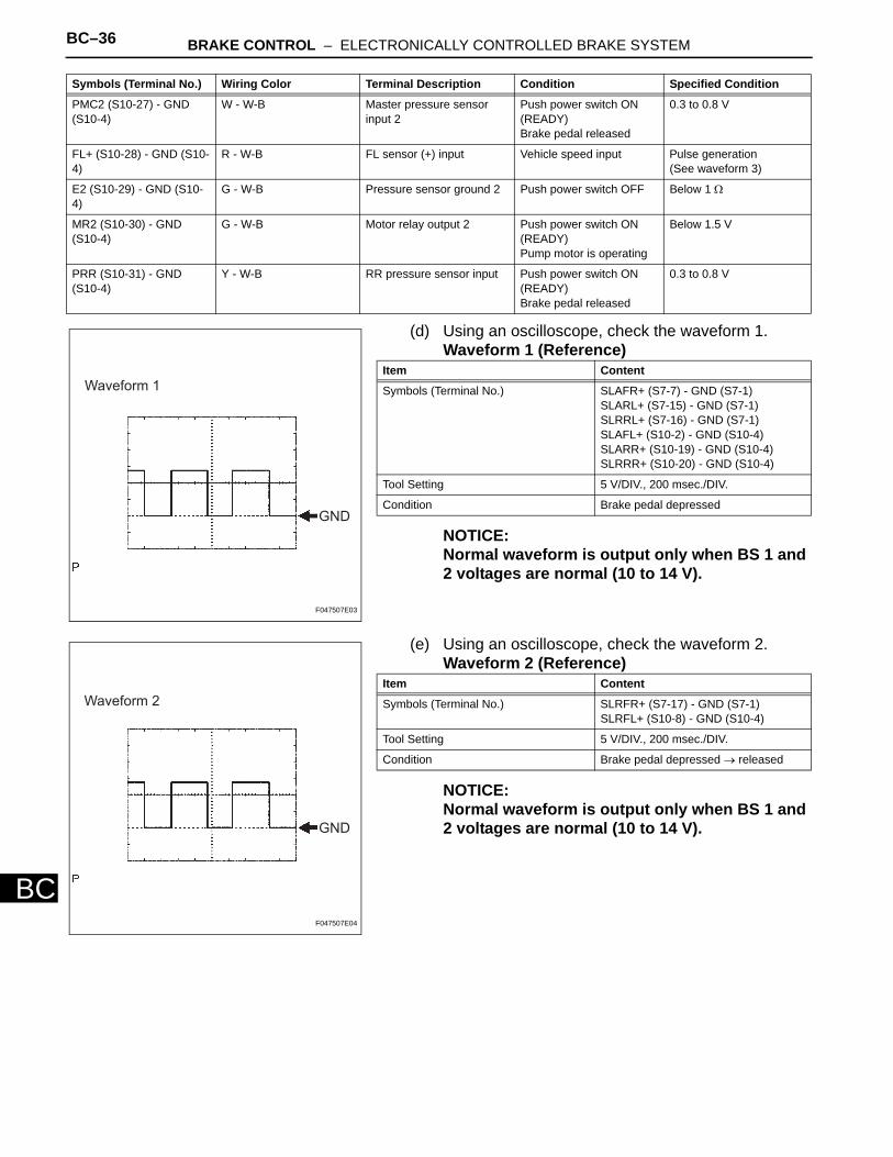
(d) Using an oscilloscope, check the waveform 1.Waveform 1 (Reference)
NOTICE:Normal waveform is output only when BS 1 and 2 voltages are normal (10 to 14 V).
(e) Using an oscilloscope, check the waveform 2.Waveform 2 (Reference)
NOTICE:Normal waveform is output only when BS 1 and 2 voltages are normal (10 to 14 V).
PMC2 (S10-27) - GND (S10-4)
W - W-B Master pressure sensor input 2
Push power switch ON (READY)Brake pedal released
0.3 to 0.8 V
FL+ (S10-28) - GND (S10-4)
R - W-B FL sensor (+) input Vehicle speed input Pulse generation(See waveform 3)
E2 (S10-29) - GND (S10-4)
G - W-B Pressure sensor ground 2 Push power switch OFF Below 1 Ω
MR2 (S10-30) - GND (S10-4)
G - W-B Motor relay output 2 Push power switch ON (READY)Pump motor is operating
Below 1.5 V
PRR (S10-31) - GND (S10-4)
Y - W-B RR pressure sensor input Push power switch ON (READY)Brake pedal released
0.3 to 0.8 V
Symbols (Terminal No.) Wiring Color Terminal Description Condition Specified Condition
GND
Waveform 1
F047507E03
Item Content
Symbols (Terminal No.) SLAFR+ (S7-7) - GND (S7-1)SLARL+ (S7-15) - GND (S7-1)SLRRL+ (S7-16) - GND (S7-1)SLAFL+ (S10-2) - GND (S10-4)SLARR+ (S10-19) - GND (S10-4)SLRRR+ (S10-20) - GND (S10-4)
Tool Setting 5 V/DIV., 200 msec./DIV.
Condition Brake pedal depressed
GND
Waveform 2
F047507E04
Item Content
Symbols (Terminal No.) SLRFR+ (S7-17) - GND (S7-1)SLRFL+ (S10-8) - GND (S10-4)
Tool Setting 5 V/DIV., 200 msec./DIV.
Condition Brake pedal depressed → released
BRAKE CONTROL – ELECTRONICALLY CONTROLLED BRAKE SYSTEM BC–37
BC
(f) Using an oscilloscope, check the waveform 3.Waveform 3 (Reference)
NOTICE:As the vehicle speed (tire rotating speed) becomes faster, the cycle becomes shorter and the output voltage becomes larger.
(g) Using an oscilloscope, check the waveform 4.Waveform 4 (Reference)
NOTICE:As the vehicle speed (tire rotating speed) becomes faster, the cycle becomes shorter.
(h) Using an oscilloscope, check the waveform 5.Waveform 5 (Reference)
GND
Waveform 3
F047509E03
Item Content
Symbols (Terminal No.) FR+ (S7-32) - GND (S7-1)RL+ (S8-35) - GND (S8-1, 2)RR+ (S9-31) - GND (S9-1, 2)FL+ (S10-28) - GND (S10-4)
Tool Setting 1 V/DIV., 200 msec./DIV.
Condition While driving at approximately 18 mph (30 km/h)
GND
Waveform 4
F047510E03
Item Content
Symbols (Terminal No.) SP1 (S8-22) - GND (S8-1, 2)
Tool Setting 5 V/DIV., 50 msec./DIV.
Condition While driving at approximately 12 mph (20 km/h)
GND
Waveform 5
F047511E03
Item Content
Symbols (Terminal No.) FAIL (S8-20) - GND (S8-1, 2)
Tool Setting 5 V/DIV., 200 msec./DIV.
Condition Power switch ON (READY)
BC–38 BRAKE CONTROL – ELECTRONICALLY CONTROLLED BRAKE SYSTEM
BC
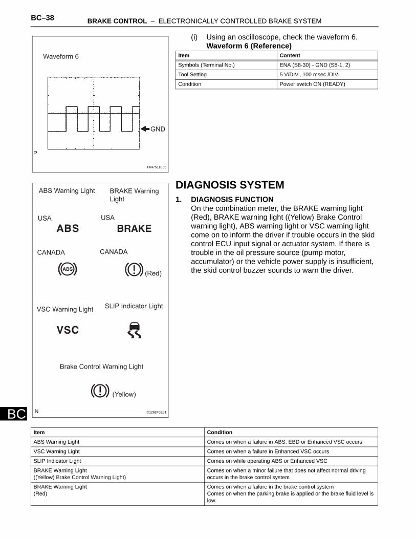
(i) Using an oscilloscope, check the waveform 6.Waveform 6 (Reference)
DIAGNOSIS SYSTEM1. DIAGNOSIS FUNCTION
On the combination meter, the BRAKE warning light (Red), BRAKE warning light ((Yellow) Brake Control warning light), ABS warning light or VSC warning light come on to inform the driver if trouble occurs in the skid control ECU input signal or actuator system. If there is trouble in the oil pressure source (pump motor, accumulator) or the vehicle power supply is insufficient, the skid control buzzer sounds to warn the driver.
GND
Waveform 6
F047511E05
Item Content
Symbols (Terminal No.) ENA (S8-30) - GND (S8-1, 2)
Tool Setting 5 V/DIV., 100 msec./DIV.
Condition Power switch ON (READY)
ABS Warning Light BRAKE Warning
Light
USA USA
CANADA CANADA
(Red)
VSC Warning LightSLIP Indicator Light
Brake Control Warning Light
(Yellow)
C126240E01
Item Condition
ABS Warning Light Comes on when a failure in ABS, EBD or Enhanced VSC occurs
VSC Warning Light Comes on when a failure in Enhanced VSC occurs
SLIP Indicator Light Comes on while operating ABS or Enhanced VSC
BRAKE Warning Light((Yellow) Brake Control Warning Light)
Comes on when a minor failure that does not affect normal driving occurs in the brake control system
BRAKE Warning Light(Red)
Comes on when a failure in the brake control systemComes on when the parking brake is applied or the brake fluid level is low.
BRAKE CONTROL – ELECTRONICALLY CONTROLLED BRAKE SYSTEM BC–39
BC
2. DIAGNOSIS DISPLAY FUNCTIONDTCs detected by the ECU can be read by connecting the intelligent tester and performing the read command. The DTC has a detailed code that can be checked on the freeze frame data screen.
3. BRAKE SYSTEM DISPLAY INITIAL CHECKTurn the power switch ON (READY) and check that the ABS warning light, VSC warning light, Brake Control warning light, BRAKE warning light and SLIP indicator light come on, and then go off after approximately 3 seconds.If any of the lights do not come on, check the bulb and the multiplex communication diagnosis.
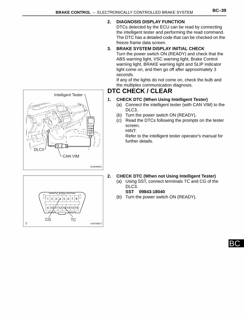
DTC CHECK / CLEAR1. CHECK DTC (When Using Intelligent Tester)
(a) Connect the intelligent tester (with CAN VIM) to the DLC3.
(b) Turn the power switch ON (READY).(c) Read the DTCs following the prompts on the tester
screen.HINT:Refer to the intelligent tester operator's manual for further details.
2. CHECK DTC (When not Using Intelligent Tester)(a) Using SST, connect terminals TC and CG of the
DLC3.SST 09843-18040
(b) Turn the power switch ON (READY).
DLC3
CAN VIM
Intelligent Tester
B126098E01
TCCGH100769E17
BC–40 BRAKE CONTROL – ELECTRONICALLY CONTROLLED BRAKE SYSTEM
BC
(c) Read the DTC from the Brake Control warning light, ABS warning light and VSC warning light on the combination meter.
HINT:• If no code appears, inspect the diagnostic circuit
or ABS warning light circuit.
• As an example, the illustration below shows the blinking patterns of the normal system code and trouble codes 11 and 21.
(d) Codes are explained in the Diagnostic Trouble Code (see page BC-47).
(e) After completing the check, disconnect terminals TC and CG of the DLC3, and turn off the display.If 2 or more DTCs are detected at the same time, the DTCs will be displayed in ascending order.
Brake Control Warning Light
(Yellow)
ABS Warning Light
USA
CANADA
VSC Warning Light
C126242E01
Light Read DTC
Brake Control warning light DTC of ECB system
ABS warning light DTC of ABS system
VSC warning light DTC of Enhanced VSC system
Trouble Area See procedure
TC and CG terminal circuit BC-194
Brake Control warning light circuit BC-182
ABS warning light circuit BC-166
VSC warning light circuit BC-171
Normal System Code
DTCs 11 and 21
ON
OFF
ON
OFF
2 sec.0.25 sec.
0.25 sec.
DTC 11 DTC 21
4 sec.
0.5 sec. 0.5 sec.1.5 sec.
2.5 sec.
C108860E01
BRAKE CONTROL – ELECTRONICALLY CONTROLLED BRAKE SYSTEM BC–41
BC
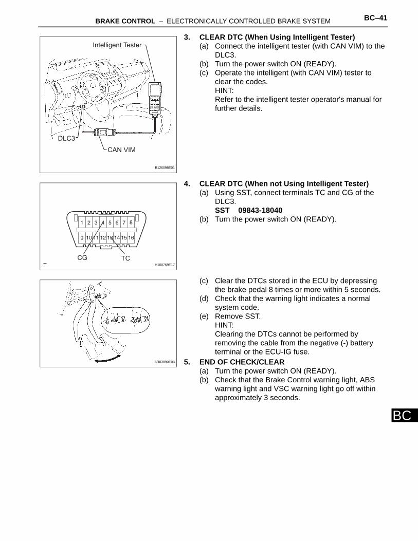
3. CLEAR DTC (When Using Intelligent Tester)(a) Connect the intelligent tester (with CAN VIM) to the
DLC3.(b) Turn the power switch ON (READY).(c) Operate the intelligent (with CAN VIM) tester to
clear the codes.HINT:Refer to the intelligent tester operator's manual for further details.
4. CLEAR DTC (When not Using Intelligent Tester)(a) Using SST, connect terminals TC and CG of the
DLC3.SST 09843-18040
(b) Turn the power switch ON (READY).
(c) Clear the DTCs stored in the ECU by depressing the brake pedal 8 times or more within 5 seconds.
(d) Check that the warning light indicates a normal system code.
(e) Remove SST.HINT:Clearing the DTCs cannot be performed by removing the cable from the negative (-) battery terminal or the ECU-IG fuse.
5. END OF CHECK/CLEAR(a) Turn the power switch ON (READY). (b) Check that the Brake Control warning light, ABS
warning light and VSC warning light go off within approximately 3 seconds.
DLC3
CAN VIM
Intelligent Tester
B126098E01
TCCGH100769E17
BR03890E03
BC–42 BRAKE CONTROL – ELECTRONICALLY CONTROLLED BRAKE SYSTEM
BC
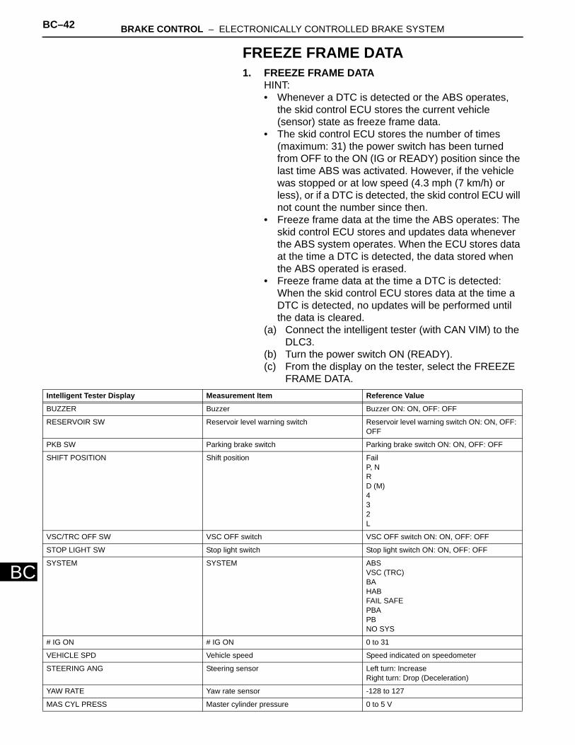
FREEZE FRAME DATA1. FREEZE FRAME DATA
HINT:• Whenever a DTC is detected or the ABS operates,
the skid control ECU stores the current vehicle (sensor) state as freeze frame data.
• The skid control ECU stores the number of times (maximum: 31) the power switch has been turned from OFF to the ON (IG or READY) position since the last time ABS was activated. However, if the vehicle was stopped or at low speed (4.3 mph (7 km/h) or less), or if a DTC is detected, the skid control ECU will not count the number since then.
• Freeze frame data at the time the ABS operates: The skid control ECU stores and updates data whenever the ABS system operates. When the ECU stores data at the time a DTC is detected, the data stored when the ABS operated is erased.
• Freeze frame data at the time a DTC is detected: When the skid control ECU stores data at the time a DTC is detected, no updates will be performed until the data is cleared.
(a) Connect the intelligent tester (with CAN VIM) to the DLC3.
(b) Turn the power switch ON (READY). (c) From the display on the tester, select the FREEZE
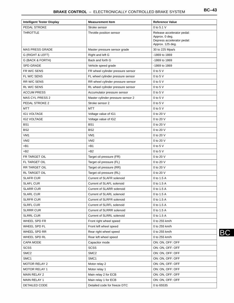
FRAME DATA.Intelligent Tester Display Measurement Item Reference Value
BUZZER Buzzer Buzzer ON: ON, OFF: OFF
RESERVOIR SW Reservoir level warning switch Reservoir level warning switch ON: ON, OFF: OFF
PKB SW Parking brake switch Parking brake switch ON: ON, OFF: OFF
SHIFT POSITION Shift position FailP, NR D (M)432L
VSC/TRC OFF SW VSC OFF switch VSC OFF switch ON: ON, OFF: OFF
STOP LIGHT SW Stop light switch Stop light switch ON: ON, OFF: OFF
SYSTEM SYSTEM ABS VSC (TRC)BAHABFAIL SAFEPBAPBNO SYS
# IG ON # IG ON 0 to 31
VEHICLE SPD Vehicle speed Speed indicated on speedometer
STEERING ANG Steering sensor Left turn: IncreaseRight turn: Drop (Deceleration)
YAW RATE Yaw rate sensor -128 to 127
MAS CYL PRESS Master cylinder pressure 0 to 5 V
BRAKE CONTROL – ELECTRONICALLY CONTROLLED BRAKE SYSTEM BC–43
BC
PEDAL STROKE Stroke sensor 0 to 5.1 V
THROTTLE Throttle position sensor Release accelerator pedal:Approx. 0 deg. Depress accelerator pedal: Approx. 125 deg.
MAS PRESS GRADE Master pressure sensor grade 30 to 225 Mpa/s
G (RIGHT & LEFT) Right and left G -1869 to 1869
G (BACK & FORTH) Back and forth G -1869 to 1869
SPD GRADE Vehicle speed grade -1869 to 1869
FR W/C SENS FR wheel cylinder pressure sensor 0 to 5 V
FL W/C SENS FL wheel cylinder pressure sensor 0 to 5 V
RR W/C SENS RR wheel cylinder pressure sensor 0 to 5 V
RL W/C SENS RL wheel cylinder pressure sensor 0 to 5 V
ACCUM PRESS Accumulator pressure sensor 0 to 5 V
MAS CYL PRESS 2 Master cylinder pressure sensor 2 0 to 5 V
PEDAL STROKE 2 Stroke sensor 2 0 to 5 V
MTT MTT 0 to 5 V
IG1 VOLTAGE Voltage value of IG1 0 to 20 V
IG2 VOLTAGE Voltage value of IG2 0 to 20 V
BS1 BS1 0 to 20 V
BS2 BS2 0 to 20 V
VM1 VM1 0 to 20 V
VM2 VM2 0 to 20 V
+B1 +B1 0 to 5 V
+B2 +B2 0 to 5 V
FR TARGET OIL Target oil pressure (FR) 0 to 20 V
FL TARGET OIL Target oil pressure (FL) 0 to 20 V
RR TARGET OIL Target oil pressure (RR) 0 to 20 V
RL TARGET OIL Target oil pressure (RL) 0 to 20 V
SLAFR CUR Current of SLAFR solenoid 0 to 1.5 A
SLAFL CUR Current of SLAFL solenoid 0 to 1.5 A
SLARR CUR Current of SLARR solenoid 0 to 1.5 A
SLARL CUR Current of SLARL solenoid 0 to 1.5 A
SLRFR CUR Current of SLRFR solenoid 0 to 1.5 A
SLRFL CUR Current of SLRFL solenoid 0 to 1.5 A
SLRRR CUR Current of SLRRR solenoid 0 to 1.5 A
SLRRL CUR Current of SLRRL solenoid 0 to 1.5 A
WHEEL SPD FR Front right wheel speed 0 to 255 km/h
WHEEL SPD FL Front left wheel speed 0 to 255 km/h
WHEEL SPD RR Rear right wheel speed 0 to 255 km/h
WHEEL SPD RL Rear left wheel speed 0 to 255 km/h
CAPA MODE Capacitor mode ON: ON, OFF: OFF
SCSS SCSS ON: ON, OFF: OFF
SMC2 SMC2 ON: ON, OFF: OFF
SMC1 SMC1 ON: ON, OFF: OFF
MOTOR RELAY 2 Motor relay 2 ON: ON, OFF: OFF
MOTOR RELAY 1 Motor relay 1 ON: ON, OFF: OFF
MAIN RELAY 2 Main relay 2 for ECB ON: ON, OFF: OFF
MAIN RELAY 1 Main relay 1 for ECB ON: ON, OFF: OFF
DETAILED CODE Detailed code for freeze DTC 0 to 65535
Intelligent Tester Display Measurement Item Reference Value
BC–44 BRAKE CONTROL – ELECTRONICALLY CONTROLLED BRAKE SYSTEM
BC
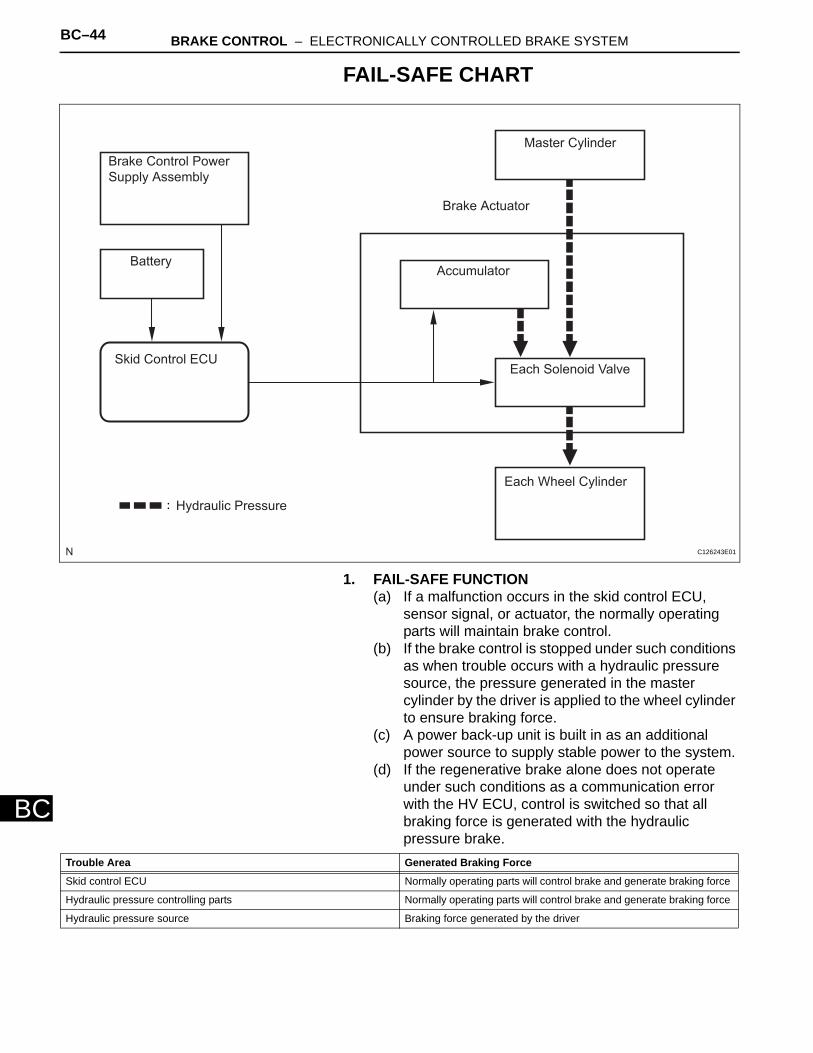
FAIL-SAFE CHART
1. FAIL-SAFE FUNCTION(a) If a malfunction occurs in the skid control ECU,
sensor signal, or actuator, the normally operating parts will maintain brake control.
(b) If the brake control is stopped under such conditions as when trouble occurs with a hydraulic pressure source, the pressure generated in the master cylinder by the driver is applied to the wheel cylinder to ensure braking force.
(c) A power back-up unit is built in as an additional power source to supply stable power to the system.
(d) If the regenerative brake alone does not operate under such conditions as a communication error with the HV ECU, control is switched so that all braking force is generated with the hydraulic pressure brake.
:
Brake Control Power
Supply Assembly
Battery
Skid Control ECU
Master Cylinder
Brake Actuator
Accumulator
Each Solenoid Valve
Each Wheel Cylinder
Hydraulic Pressure
C126243E01
Trouble Area Generated Braking Force
Skid control ECU Normally operating parts will control brake and generate braking force
Hydraulic pressure controlling parts Normally operating parts will control brake and generate braking force
Hydraulic pressure source Braking force generated by the driver
BRAKE CONTROL – ELECTRONICALLY CONTROLLED BRAKE SYSTEM BC–45
BC
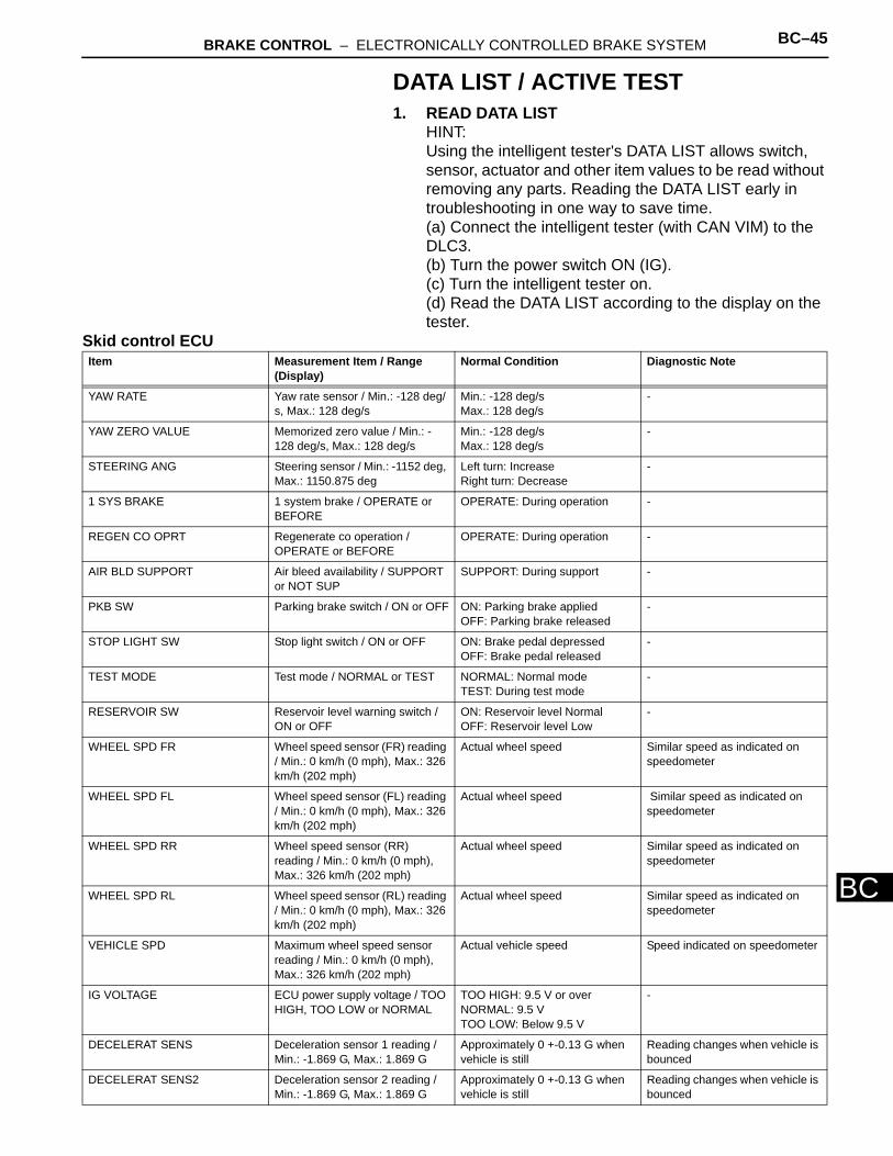
DATA LIST / ACTIVE TEST1. READ DATA LIST
HINT:Using the intelligent tester's DATA LIST allows switch, sensor, actuator and other item values to be read without removing any parts. Reading the DATA LIST early in troubleshooting in one way to save time.(a) Connect the intelligent tester (with CAN VIM) to the DLC3.(b) Turn the power switch ON (IG).(c) Turn the intelligent tester on.(d) Read the DATA LIST according to the display on the tester.
Skid control ECUItem Measurement Item / Range
(Display)Normal Condition Diagnostic Note
YAW RATE Yaw rate sensor / Min.: -128 deg/s, Max.: 128 deg/s
Min.: -128 deg/sMax.: 128 deg/s
-
YAW ZERO VALUE Memorized zero value / Min.: -128 deg/s, Max.: 128 deg/s
Min.: -128 deg/sMax.: 128 deg/s
-
STEERING ANG Steering sensor / Min.: -1152 deg, Max.: 1150.875 deg
Left turn: Increase Right turn: Decrease
-
1 SYS BRAKE 1 system brake / OPERATE or BEFORE
OPERATE: During operation -
REGEN CO OPRT Regenerate co operation / OPERATE or BEFORE
OPERATE: During operation -
AIR BLD SUPPORT Air bleed availability / SUPPORT or NOT SUP
SUPPORT: During support -
PKB SW Parking brake switch / ON or OFF ON: Parking brake appliedOFF: Parking brake released
-
STOP LIGHT SW Stop light switch / ON or OFF ON: Brake pedal depressedOFF: Brake pedal released
-
TEST MODE Test mode / NORMAL or TEST NORMAL: Normal modeTEST: During test mode
-
RESERVOIR SW Reservoir level warning switch / ON or OFF
ON: Reservoir level NormalOFF: Reservoir level Low
-
WHEEL SPD FR Wheel speed sensor (FR) reading / Min.: 0 km/h (0 mph), Max.: 326 km/h (202 mph)
Actual wheel speed Similar speed as indicated on speedometer
WHEEL SPD FL Wheel speed sensor (FL) reading / Min.: 0 km/h (0 mph), Max.: 326 km/h (202 mph)
Actual wheel speed Similar speed as indicated on speedometer
WHEEL SPD RR Wheel speed sensor (RR) reading / Min.: 0 km/h (0 mph), Max.: 326 km/h (202 mph)
Actual wheel speed Similar speed as indicated on speedometer
WHEEL SPD RL Wheel speed sensor (RL) reading / Min.: 0 km/h (0 mph), Max.: 326 km/h (202 mph)
Actual wheel speed Similar speed as indicated on speedometer
VEHICLE SPD Maximum wheel speed sensor reading / Min.: 0 km/h (0 mph), Max.: 326 km/h (202 mph)
Actual vehicle speed Speed indicated on speedometer
IG VOLTAGE ECU power supply voltage / TOO HIGH, TOO LOW or NORMAL
TOO HIGH: 9.5 V or overNORMAL: 9.5 VTOO LOW: Below 9.5 V
-
DECELERAT SENS Deceleration sensor 1 reading / Min.: -1.869 G, Max.: 1.869 G
Approximately 0 +-0.13 G when vehicle is still
Reading changes when vehicle is bounced
DECELERAT SENS2 Deceleration sensor 2 reading / Min.: -1.869 G, Max.: 1.869 G
Approximately 0 +-0.13 G when vehicle is still
Reading changes when vehicle is bounced
BC–46 BRAKE CONTROL – ELECTRONICALLY CONTROLLED BRAKE SYSTEM
BC
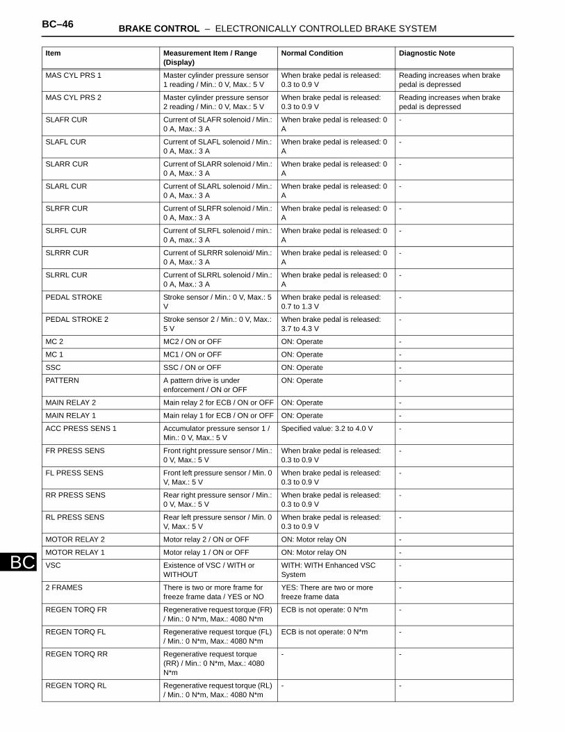
MAS CYL PRS 1 Master cylinder pressure sensor 1 reading / Min.: 0 V, Max.: 5 V
When brake pedal is released: 0.3 to 0.9 V
Reading increases when brake pedal is depressed
MAS CYL PRS 2 Master cylinder pressure sensor 2 reading / Min.: 0 V, Max.: 5 V
When brake pedal is released: 0.3 to 0.9 V
Reading increases when brake pedal is depressed
SLAFR CUR Current of SLAFR solenoid / Min.: 0 A, Max.: 3 A
When brake pedal is released: 0 A
-
SLAFL CUR Current of SLAFL solenoid / Min.: 0 A, Max.: 3 A
When brake pedal is released: 0 A
-
SLARR CUR Current of SLARR solenoid / Min.: 0 A, Max.: 3 A
When brake pedal is released: 0 A
-
SLARL CUR Current of SLARL solenoid / Min.: 0 A, Max.: 3 A
When brake pedal is released: 0 A
-
SLRFR CUR Current of SLRFR solenoid / Min.: 0 A, Max.: 3 A
When brake pedal is released: 0 A
-
SLRFL CUR Current of SLRFL solenoid / min.: 0 A, max.: 3 A
When brake pedal is released: 0 A
-
SLRRR CUR Current of SLRRR solenoid/ Min.: 0 A, Max.: 3 A
When brake pedal is released: 0 A
-
SLRRL CUR Current of SLRRL solenoid / Min.: 0 A, Max.: 3 A
When brake pedal is released: 0 A
-
PEDAL STROKE Stroke sensor / Min.: 0 V, Max.: 5 V
When brake pedal is released: 0.7 to 1.3 V
-
PEDAL STROKE 2 Stroke sensor 2 / Min.: 0 V, Max.: 5 V
When brake pedal is released: 3.7 to 4.3 V
-
MC 2 MC2 / ON or OFF ON: Operate -
MC 1 MC1 / ON or OFF ON: Operate -
SSC SSC / ON or OFF ON: Operate -
PATTERN A pattern drive is under enforcement / ON or OFF
ON: Operate -
MAIN RELAY 2 Main relay 2 for ECB / ON or OFF ON: Operate -
MAIN RELAY 1 Main relay 1 for ECB / ON or OFF ON: Operate -
ACC PRESS SENS 1 Accumulator pressure sensor 1 / Min.: 0 V, Max.: 5 V
Specified value: 3.2 to 4.0 V -
FR PRESS SENS Front right pressure sensor / Min.: 0 V, Max.: 5 V
When brake pedal is released: 0.3 to 0.9 V
-
FL PRESS SENS Front left pressure sensor / Min. 0 V, Max.: 5 V
When brake pedal is released: 0.3 to 0.9 V
-
RR PRESS SENS Rear right pressure sensor / Min.: 0 V, Max.: 5 V
When brake pedal is released: 0.3 to 0.9 V
-
RL PRESS SENS Rear left pressure sensor / Min. 0 V, Max.: 5 V
When brake pedal is released: 0.3 to 0.9 V
-
MOTOR RELAY 2 Motor relay 2 / ON or OFF ON: Motor relay ON -
MOTOR RELAY 1 Motor relay 1 / ON or OFF ON: Motor relay ON -
VSC Existence of VSC / WITH or WITHOUT
WITH: WITH Enhanced VSC System
-
2 FRAMES There is two or more frame for freeze frame data / YES or NO
YES: There are two or more freeze frame data
-
REGEN TORQ FR Regenerative request torque (FR) / Min.: 0 N*m, Max.: 4080 N*m
ECB is not operate: 0 N*m -
REGEN TORQ FL Regenerative request torque (FL) / Min.: 0 N*m, Max.: 4080 N*m
ECB is not operate: 0 N*m -
REGEN TORQ RR Regenerative request torque (RR) / Min.: 0 N*m, Max.: 4080 N*m
- -
REGEN TORQ RL Regenerative request torque (RL) / Min.: 0 N*m, Max.: 4080 N*m
- -
Item Measurement Item / Range (Display)
Normal Condition Diagnostic Note
BRAKE CONTROL – ELECTRONICALLY CONTROLLED BRAKE SYSTEM BC–47
BC
SPD SEN FR FR speed sensor open detection / OPN-DET or NORMAL
NORMAL: Normal condition -
SPD SEN FL FL speed sensor open detection / OPN-DET or NORMAL
NORMAL: Normal condition -
SPD SEN RR RR speed sensor open detection / OPN-DET or NORMAL
NORMAL: Normal condition -
SPD SEN RL RL speed sensor open detection / OPN-DET or NORMAL
NORMAL: Normal condition -
YAW RATE SEN Yaw rate sensor open detection / OPN-DET or NORMAL
NORMAL: Normal condition -
DECELE SEN Deceleration sensor open detection / OPN-DET or NORMAL
NORMAL: Normal condition -
STEERING SEN Steering sensor open detection / OPN-DET or NORMAL
NORMAL: Normal condition -
M/C SEN 1 Master cylinder pressure sensor 1 open detection / OPN-DET or NORMAL
NORMAL: Normal condition -
M/C SEN 2 Master cylinder pressure sensor 2 open detection / OPN-DET or NORMAL
NORMAL: Normal condition -
STROKE SEN 1 Stroke sensor open detection / OPN-DET or NORMAL
NORMAL: Normal condition -
FR W/C SEN FR wheel cylinder pressure sensor open detection / OPN-DET or NORMAL
NORMAL: Normal condition -
FL W/C SEN FL wheel cylinder pressure sensor open detection / OPN-DET or NORMAL
NORMAL: Normal condition -
RR W/C SEN RR wheel cylinder pressure sensor open detection / OPN-DET or NORMAL
NORMAL: Normal condition -
RL W/C SEN RL wheel cylinder pressure sensor open detection / OPN-DET or NORMAL
NORMAL: Normal condition -
HV COM HV communication open detection / OPN-DET or NORMAL
NORMAL: Normal condition -
ACC SEN Accumulator pressure sensor open detection / ERROR or NORMAL
ERROR: Momentary interruptionNORMAL: Normal condition
-
BUZZER Buzzer / ON or OFF ON: Buzzer ONOFF: Buzzer OFF
-
RESERVOIR SW Reservoir level warning switch / ON or OFF
ON: Reservoir level normalOFF: Reservoir level low
-
SHIFT POSITION Shift position / FAIL / L / 2 / 3 / 4 / D (M) / R / P.N
- -
VSC/TRC OFF SW TRAC control switch / ON or OFF ON: TRAC control switch ON -
STOP LIGHT SW Stop light switch / ON or OFF ON: Operate -
SYSTEM SYSTEM / ABS / VSC (TRAC) / BA / HAB / FAIL SAFE / PB / NOSYS
- -
# IG ON # IG ON / 0 to 31 0 -
STEERING ANG Steering sensor / Min.: -1152 deg, Max.: 1150.875 deg
Left turn: IncreaseRight turn: Decrease
-
YAW RATE Yaw rate sensor/ Min.: -128 deg/s, Max.: 128 deg/s
Min.: -128 deg/sMax.: 128 deg/s
-
Item Measurement Item / Range (Display)
Normal Condition Diagnostic Note
BC–48 BRAKE CONTROL – ELECTRONICALLY CONTROLLED BRAKE SYSTEM
BC
2. PERFORM ACTIVE TESTHINT:Performing the intelligent tester's ACTIVE TEST allows relay, VSV, actuator and other items to be operated without removing any parts. Performing the ACTIVE TEST early in troubleshooting is one way to save time.The DATA LIST can be displayed during the ACTIVE TEST.(a) Connect the intelligent tester (with CAN VIM) to the
DLC3.(b) Turn the power switch ON (READY).(c) Perform the ACTIVE TEST according to the display
on the tester.Skid control ECU
MAS CYL PRESS Master cylinder pressure / Min.: 0 V, Max.: 5 V
When brake pedal is released: 0.3 to 0.9 V
Reading increases when brake pedal is depressed
PEDAL STROKE Stroke sensor / Min.: 0 V, Max.: 5 V
When brake pedal is released (SKS1): 0.7 to 1.5 VWhen brake pedal is released (SKS2): 3.7 to 4.3 V
-
THROTTLE Throttle position sensor / Min.: 0 deg, Max.: 125 deg
Release accelerator pedal: Approx. 0 deg.Depress accelerator pedal: Approx. 90 deg.
-
MAS PRESS GRADE Master pressure sensor grade / Min.: -30Mpa/s, Max.: 225 Mpa/s
When brake pedal is released: 0 MPa
-
G (RIGHT & LEFT) Right and left G / Min.: -1.869 G, Max.: 1.869 G
Approximately 0 +-0.13 G when vehicle is still
-
G (BACK & FORTH) Back and forth G / Min.: -1.869 G, Max.: 1.869 G
Approximately 0 +-0.13 G when vehicle is still
-
SPD GRADE Vehicle speed grade /Min.: -1.869 G, Max.: 1.869 G
Approximately 0 +-0.13 G when vehicle is still
-
# CODES Number of DTC recorded / Min.: 0, Max.: 255
Min.: 0, max.: 39 -
Item Measurement Item / Range (Display)
Normal Condition Diagnostic Note
Item Test Details Diagnostic Note
ABS WARN LIGHT Turns ABS warning light ON / OFF Observe combination meter
VSC WARN LIGHT Turns VSC warning light ON / OFF Observe combination meter
SLIP INDI LIGHT Turns SLIP indicator light ON / OFF Observe combination meter
BRAKE WARN LIGHT Turns BRAKE warning light ON / OFF Observe combination meter
VSC/BR WARN BUZ Turns VSC / BRAKE warning buzzer ON / OFF
Buzzer can be heard
ECB INDI LIGHT Turns Brake Control warning light ON / OFF Observe combination meter
MAIN RELAY 1 Turns MAIN RELAY 1 ON / OFF Operation of solenoid (clicking sound) can be heard
MAIN RELAY 2 Turns MAIN RELAY 2 ON / OFF Operation of solenoid (clicking sound) can be heard
MC 1 Turns Master cut valve 1 activation ON / OFF Operation of solenoid (clicking sound) can be heard
MC 2 Turns Master cut valve 2 activation ON / OFF Operation of solenoid (clicking sound) can be heard
MOTOR RELAY 1 Turns MOTOR RELAY 1 ON / OFF Operation of solenoid (clicking sound) can be heard
MOTOR RELAY 2 Turns MOTOR RELAY 2 ON / OFF Operation of solenoid (clicking sound) can be heard
BRAKE CONTROL – ELECTRONICALLY CONTROLLED BRAKE SYSTEM BC–49
BC
ECB INVALID Turns ECB invalid ON / OFF Operation of solenoid (clicking sound) can be heard
ACC PATTERN Actuator air bleeding pattern activation ON / OFF
Operation of solenoid (clicking sound) can be heard
SCC PATTERN Stroke simulator cut valve pattern activation ON / OFF
Operation of solenoid (clicking sound) can be heard
POWER SUPPLY 1 Power supply air bleeding pattern activation 1 ON / OFF
Operation of solenoid (clicking sound) can be heard
POWER SUPPLY 2 Power supply air bleeding pattern activation 2 ON / OFF
Operation of solenoid (clicking sound) can be heard
RL AIR BLEEDING RL wheel air bleeding pattern activation ON / OFF
Operation of solenoid (clicking sound) can be heard
RR AIR BLEEDING RR wheel air bleeding pattern activation ON / OFF
Operation of solenoid (clicking sound) can be heard
ZERO DOWN Accumulator zero down activation ON / OFF Operation of solenoid (clicking sound) can be heard
PUMP PATTERN Pump check pattern activation ON / OFF Operation of solenoid (clicking sound) can be heard
DRAIN PATTERN Drain system air bleeding pattern activation ON / OFF
Operation of solenoid (clicking sound) can be heard
Item Test Details Diagnostic Note
BC–50 BRAKE CONTROL – ELECTRONICALLY CONTROLLED BRAKE SYSTEM
BC
DIAGNOSTIC TROUBLE CODE CHARTHINT:If a malfunction code is displayed during the DTC check, check the circuit indicated by the DTC. For details of each code, refer to the respective "DTC No." in the DTC chart.
DTC chart of ABSDTC No. Detection Item INF Code Trouble Area See page
C0200/31 Front Speed Sensor RH Circuit
251252253254256257258259260261262
- Right front speed sensor- Speed sensor circuit- Sensor rotor- Sensor installation
BC-54
C0205/32 Front Speed Sensor LH Circuit
264265266267268269270271272273274275
- Left front speed sensor- Speed sensor circuit- Sensor rotor- Sensor installation
BC-54
C0210/33 Rear Speed Sensor RH Circuit
277278279280281282283284285286287288
- Right rear speed sensor- Speed sensor circuit- Sensor rotor- Sensor installation
BC-61
C0215/34 Rear Speed Sensor LH Circuit
290291292293294295296297298299300301
- Left rear speed sensor- Speed sensor circuit- Sensor rotor- Sensor installation
BC-61
C1235/35 Foreign Object is Attached on Tip of Front Speed Sensor RH
302 - Right front speed sensor- Speed sensor circuit- Sensor installation
BC-79
C1236/36 Foreign Object is Attached on Tip of Front Speed Sensor LH
303 - Left front speed sensor- Speed sensor circuit- Sensor installation
BC-79
C1238/38 Foreign Object is Attached on Tip of Rear Speed Sensor RH
304 - Right rear speed sensor- Speed sensor circuit- Sensor installation
BC-79
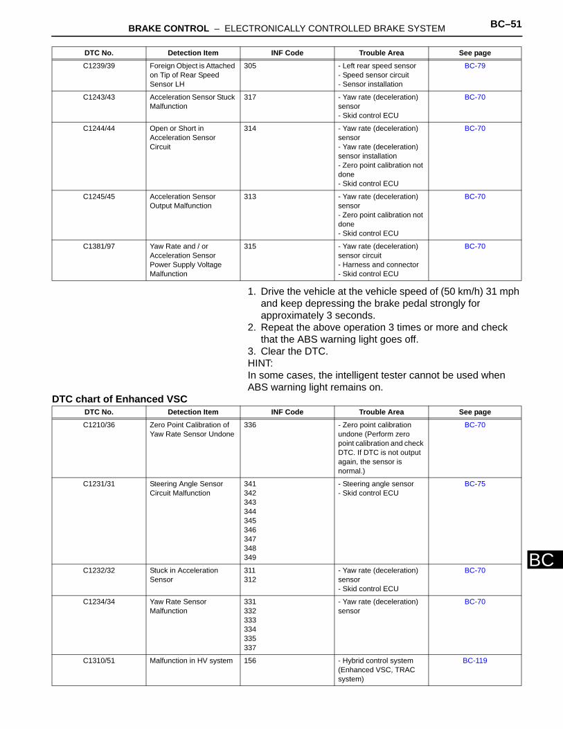
BRAKE CONTROL – ELECTRONICALLY CONTROLLED BRAKE SYSTEM BC–51
BC
1. Drive the vehicle at the vehicle speed of (50 km/h) 31 mph and keep depressing the brake pedal strongly for approximately 3 seconds.
2. Repeat the above operation 3 times or more and check that the ABS warning light goes off.
3. Clear the DTC.HINT:In some cases, the intelligent tester cannot be used when ABS warning light remains on.
DTC chart of Enhanced VSC
C1239/39 Foreign Object is Attached on Tip of Rear Speed Sensor LH
305 - Left rear speed sensor- Speed sensor circuit- Sensor installation
BC-79
C1243/43 Acceleration Sensor Stuck Malfunction
317 - Yaw rate (deceleration) sensor- Skid control ECU
BC-70
C1244/44 Open or Short in Acceleration Sensor Circuit
314 - Yaw rate (deceleration) sensor- Yaw rate (deceleration) sensor installation- Zero point calibration not done- Skid control ECU
BC-70
C1245/45 Acceleration Sensor Output Malfunction
313 - Yaw rate (deceleration) sensor- Zero point calibration not done- Skid control ECU
BC-70
C1381/97 Yaw Rate and / or Acceleration Sensor Power Supply Voltage Malfunction
315 - Yaw rate (deceleration) sensor circuit- Harness and connector- Skid control ECU
BC-70
DTC No. Detection Item INF Code Trouble Area See page
DTC No. Detection Item INF Code Trouble Area See page
C1210/36 Zero Point Calibration of Yaw Rate Sensor Undone
336 - Zero point calibration undone (Perform zero point calibration and check DTC. If DTC is not output again, the sensor is normal.)
BC-70
C1231/31 Steering Angle Sensor Circuit Malfunction
341342343344345346347348349
- Steering angle sensor- Skid control ECU
BC-75
C1232/32 Stuck in Acceleration Sensor
311312
- Yaw rate (deceleration) sensor- Skid control ECU
BC-70
C1234/34 Yaw Rate Sensor Malfunction
331332333334335337
- Yaw rate (deceleration) sensor
BC-70
C1310/51 Malfunction in HV system 156 - Hybrid control system (Enhanced VSC, TRAC system)
BC-119
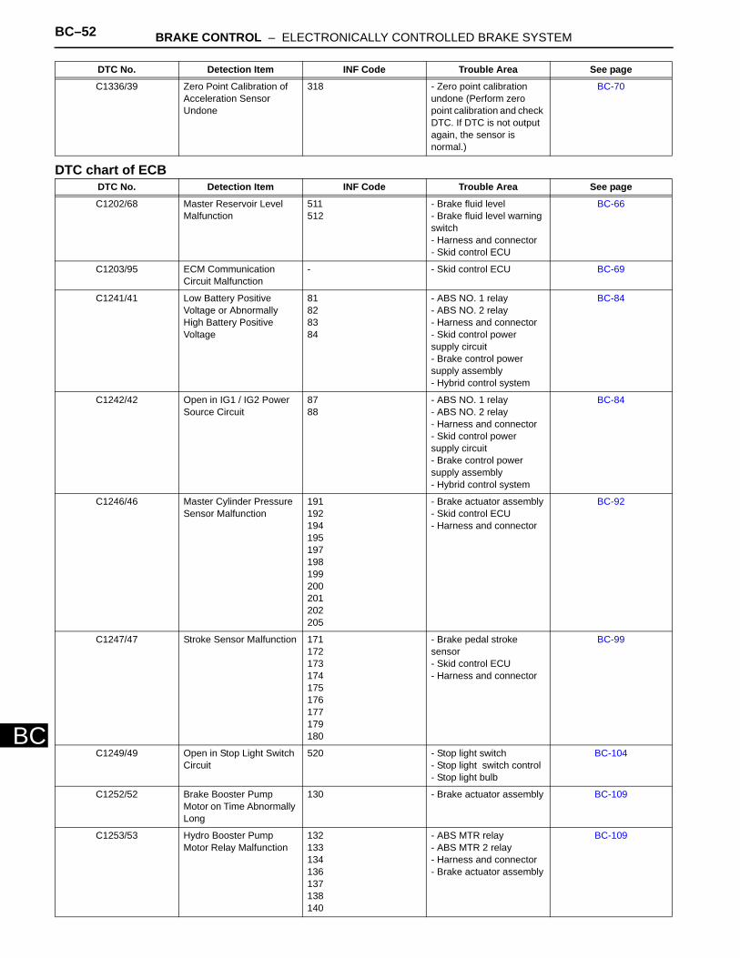
BC–52 BRAKE CONTROL – ELECTRONICALLY CONTROLLED BRAKE SYSTEM
BC
DTC chart of ECB
C1336/39 Zero Point Calibration of Acceleration Sensor Undone
318 - Zero point calibration undone (Perform zero point calibration and check DTC. If DTC is not output again, the sensor is normal.)
BC-70
DTC No. Detection Item INF Code Trouble Area See page
C1202/68 Master Reservoir Level Malfunction
511512
- Brake fluid level- Brake fluid level warning switch- Harness and connector- Skid control ECU
BC-66
C1203/95 ECM Communication Circuit Malfunction
- - Skid control ECU BC-69
C1241/41 Low Battery Positive Voltage or Abnormally High Battery Positive Voltage
81828384
- ABS NO. 1 relay- ABS NO. 2 relay- Harness and connector- Skid control power supply circuit- Brake control power supply assembly- Hybrid control system
BC-84
C1242/42 Open in IG1 / IG2 Power Source Circuit
8788
- ABS NO. 1 relay- ABS NO. 2 relay- Harness and connector- Skid control power supply circuit- Brake control power supply assembly- Hybrid control system
BC-84
C1246/46 Master Cylinder Pressure Sensor Malfunction
191192194195197198199200201202205
- Brake actuator assembly- Skid control ECU- Harness and connector
BC-92
C1247/47 Stroke Sensor Malfunction 171172173174175176177179180
- Brake pedal stroke sensor- Skid control ECU- Harness and connector
BC-99
C1249/49 Open in Stop Light Switch Circuit
520 - Stop light switch- Stop light switch control- Stop light bulb
BC-104
C1252/52 Brake Booster Pump Motor on Time Abnormally Long
130 - Brake actuator assembly BC-109
C1253/53 Hydro Booster Pump Motor Relay Malfunction
132133134136137138140
- ABS MTR relay- ABS MTR 2 relay- Harness and connector- Brake actuator assembly
BC-109
DTC No. Detection Item INF Code Trouble Area See page
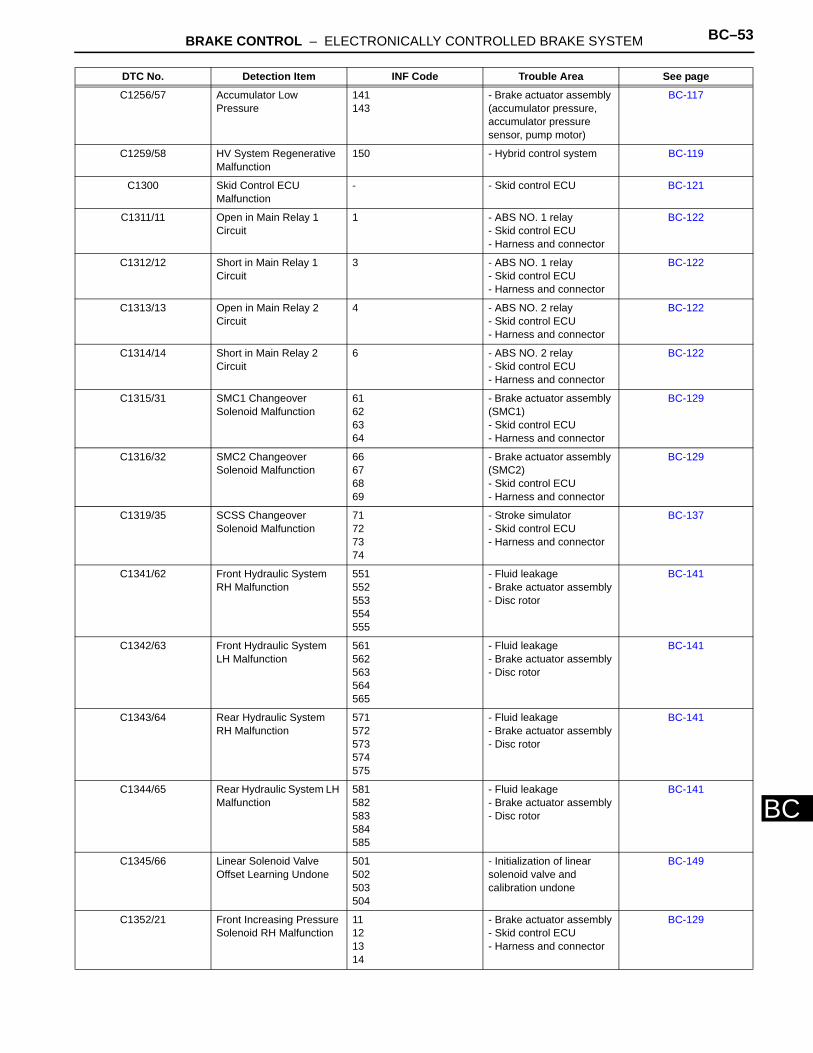
BRAKE CONTROL – ELECTRONICALLY CONTROLLED BRAKE SYSTEM BC–53
BC
C1256/57 Accumulator Low Pressure
141143
- Brake actuator assembly (accumulator pressure, accumulator pressure sensor, pump motor)
BC-117
C1259/58 HV System Regenerative Malfunction
150 - Hybrid control system BC-119
C1300 Skid Control ECU Malfunction
- - Skid control ECU BC-121
C1311/11 Open in Main Relay 1 Circuit
1 - ABS NO. 1 relay- Skid control ECU- Harness and connector
BC-122
C1312/12 Short in Main Relay 1 Circuit
3 - ABS NO. 1 relay- Skid control ECU- Harness and connector
BC-122
C1313/13 Open in Main Relay 2 Circuit
4 - ABS NO. 2 relay- Skid control ECU- Harness and connector
BC-122
C1314/14 Short in Main Relay 2 Circuit
6 - ABS NO. 2 relay- Skid control ECU- Harness and connector
BC-122
C1315/31 SMC1 Changeover Solenoid Malfunction
61626364
- Brake actuator assembly (SMC1)- Skid control ECU- Harness and connector
BC-129
C1316/32 SMC2 Changeover Solenoid Malfunction
66676869
- Brake actuator assembly (SMC2)- Skid control ECU- Harness and connector
BC-129
C1319/35 SCSS Changeover Solenoid Malfunction
71727374
- Stroke simulator- Skid control ECU- Harness and connector
BC-137
C1341/62 Front Hydraulic System RH Malfunction
551552553554555
- Fluid leakage- Brake actuator assembly- Disc rotor
BC-141
C1342/63 Front Hydraulic System LH Malfunction
561562563564565
- Fluid leakage- Brake actuator assembly- Disc rotor
BC-141
C1343/64 Rear Hydraulic System RH Malfunction
571572573574575
- Fluid leakage- Brake actuator assembly- Disc rotor
BC-141
C1344/65 Rear Hydraulic System LH Malfunction
581582583584585
- Fluid leakage- Brake actuator assembly- Disc rotor
BC-141
C1345/66 Linear Solenoid Valve Offset Learning Undone
501502503504
- Initialization of linear solenoid valve and calibration undone
BC-149
C1352/21 Front Increasing Pressure Solenoid RH Malfunction
11121314
- Brake actuator assembly- Skid control ECU- Harness and connector
BC-129
DTC No. Detection Item INF Code Trouble Area See page
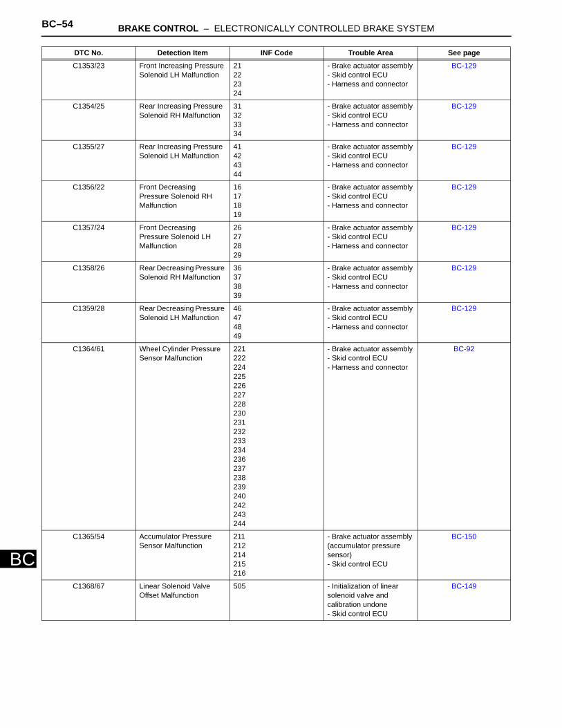
BC–54 BRAKE CONTROL – ELECTRONICALLY CONTROLLED BRAKE SYSTEM
BC
C1353/23 Front Increasing Pressure Solenoid LH Malfunction
21222324
- Brake actuator assembly- Skid control ECU- Harness and connector
BC-129
C1354/25 Rear Increasing Pressure Solenoid RH Malfunction
31323334
- Brake actuator assembly- Skid control ECU- Harness and connector
BC-129
C1355/27 Rear Increasing Pressure Solenoid LH Malfunction
41424344
- Brake actuator assembly- Skid control ECU- Harness and connector
BC-129
C1356/22 Front Decreasing Pressure Solenoid RH Malfunction
16171819
- Brake actuator assembly- Skid control ECU- Harness and connector
BC-129
C1357/24 Front Decreasing Pressure Solenoid LH Malfunction
26272829
- Brake actuator assembly- Skid control ECU- Harness and connector
BC-129
C1358/26 Rear Decreasing Pressure Solenoid RH Malfunction
36373839
- Brake actuator assembly- Skid control ECU- Harness and connector
BC-129
C1359/28 Rear Decreasing Pressure Solenoid LH Malfunction
46474849
- Brake actuator assembly- Skid control ECU- Harness and connector
BC-129
C1364/61 Wheel Cylinder Pressure Sensor Malfunction
221222224225226227228230231232233234236237238239240242243244
- Brake actuator assembly- Skid control ECU- Harness and connector
BC-92
C1365/54 Accumulator Pressure Sensor Malfunction
211212214215216
- Brake actuator assembly (accumulator pressure sensor)- Skid control ECU
BC-150
C1368/67 Linear Solenoid Valve Offset Malfunction
505 - Initialization of linear solenoid valve and calibration undone- Skid control ECU
BC-149
DTC No. Detection Item INF Code Trouble Area See page
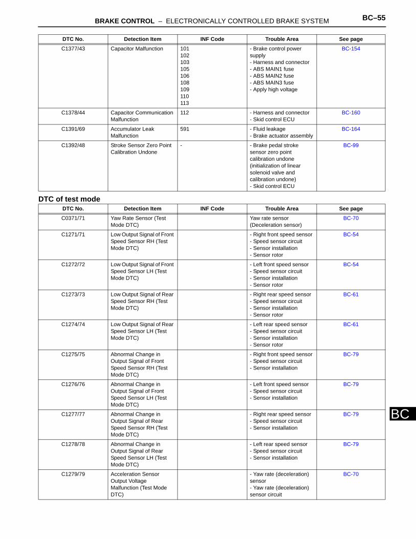
BRAKE CONTROL – ELECTRONICALLY CONTROLLED BRAKE SYSTEM BC–55
BC
DTC of test mode
C1377/43 Capacitor Malfunction 101102103105106108109110113
- Brake control power supply- Harness and connector- ABS MAIN1 fuse- ABS MAIN2 fuse- ABS MAIN3 fuse- Apply high voltage
BC-154
C1378/44 Capacitor Communication Malfunction
112 - Harness and connector- Skid control ECU
BC-160
C1391/69 Accumulator Leak Malfunction
591 - Fluid leakage- Brake actuator assembly
BC-164
C1392/48 Stroke Sensor Zero Point Calibration Undone
- - Brake pedal stroke sensor zero point calibration undone (initialization of linear solenoid valve and calibration undone)- Skid control ECU
BC-99
DTC No. Detection Item INF Code Trouble Area See page
C0371/71 Yaw Rate Sensor (Test Mode DTC)
Yaw rate sensor (Deceleration sensor)
BC-70
C1271/71 Low Output Signal of Front Speed Sensor RH (Test Mode DTC)
- Right front speed sensor- Speed sensor circuit- Sensor installation- Sensor rotor
BC-54
C1272/72 Low Output Signal of Front Speed Sensor LH (Test Mode DTC)
- Left front speed sensor- Speed sensor circuit- Sensor installation- Sensor rotor
BC-54
C1273/73 Low Output Signal of Rear Speed Sensor RH (Test Mode DTC)
- Right rear speed sensor- Speed sensor circuit- Sensor installation- Sensor rotor
BC-61
C1274/74 Low Output Signal of Rear Speed Sensor LH (Test Mode DTC)
- Left rear speed sensor- Speed sensor circuit- Sensor installation- Sensor rotor
BC-61
C1275/75 Abnormal Change in Output Signal of Front Speed Sensor RH (Test Mode DTC)
- Right front speed sensor- Speed sensor circuit- Sensor installation
BC-79
C1276/76 Abnormal Change in Output Signal of Front Speed Sensor LH (Test Mode DTC)
- Left front speed sensor- Speed sensor circuit- Sensor installation
BC-79
C1277/77 Abnormal Change in Output Signal of Rear Speed Sensor RH (Test Mode DTC)
- Right rear speed sensor- Speed sensor circuit- Sensor installation
BC-79
C1278/78 Abnormal Change in Output Signal of Rear Speed Sensor LH (Test Mode DTC)
- Left rear speed sensor- Speed sensor circuit- Sensor installation
BC-79
C1279/79 Acceleration Sensor Output Voltage Malfunction (Test Mode DTC)
- Yaw rate (deceleration) sensor- Yaw rate (deceleration) sensor circuit
BC-70
DTC No. Detection Item INF Code Trouble Area See page
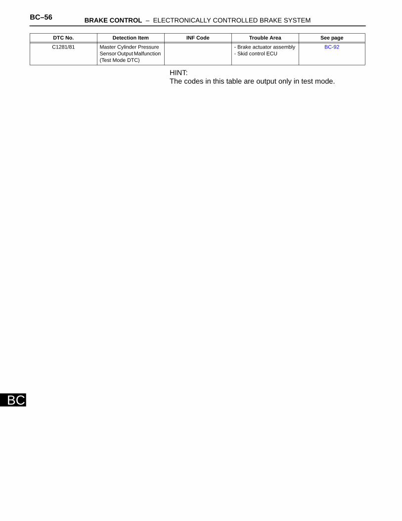
BC–56 BRAKE CONTROL – ELECTRONICALLY CONTROLLED BRAKE SYSTEM
BC
HINT:The codes in this table are output only in test mode.
C1281/81 Master Cylinder Pressure Sensor Output Malfunction (Test Mode DTC)
- Brake actuator assembly- Skid control ECU
BC-92
DTC No. Detection Item INF Code Trouble Area See page
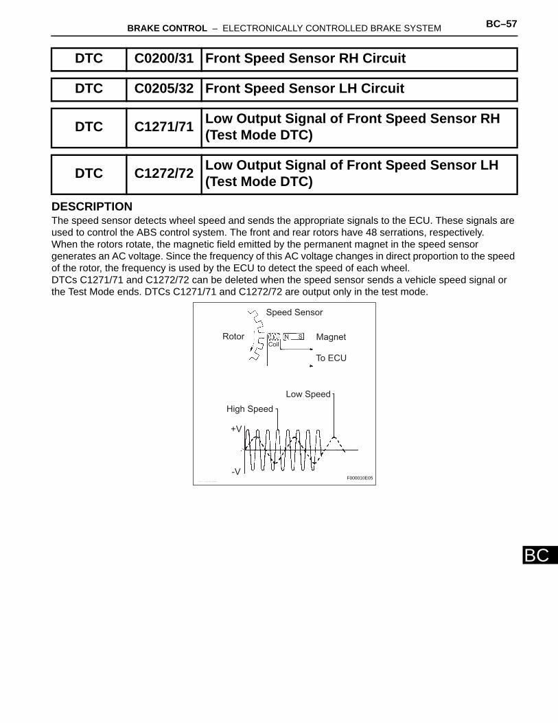
BRAKE CONTROL – ELECTRONICALLY CONTROLLED BRAKE SYSTEM BC–57
BC
DESCRIPTIONThe speed sensor detects wheel speed and sends the appropriate signals to the ECU. These signals are used to control the ABS control system. The front and rear rotors have 48 serrations, respectively. When the rotors rotate, the magnetic field emitted by the permanent magnet in the speed sensor generates an AC voltage. Since the frequency of this AC voltage changes in direct proportion to the speed of the rotor, the frequency is used by the ECU to detect the speed of each wheel.DTCs C1271/71 and C1272/72 can be deleted when the speed sensor sends a vehicle speed signal or the Test Mode ends. DTCs C1271/71 and C1272/72 are output only in the test mode.
DTC C0200/31 Front Speed Sensor RH Circuit
DTC C0205/32 Front Speed Sensor LH Circuit
DTC C1271/71 Low Output Signal of Front Speed Sensor RH (Test Mode DTC)
DTC C1272/72 Low Output Signal of Front Speed Sensor LH (Test Mode DTC)
Speed Sensor
Magnet
To ECU
Rotor
Low Speed
High Speed
+V
-V
N S
Coil
F000010E05
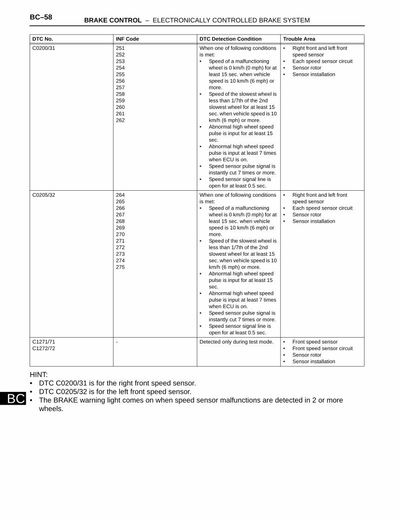
BC–58 BRAKE CONTROL – ELECTRONICALLY CONTROLLED BRAKE SYSTEM
BC
HINT:• DTC C0200/31 is for the right front speed sensor. • DTC C0205/32 is for the left front speed sensor. • The BRAKE warning light comes on when speed sensor malfunctions are detected in 2 or more
wheels.
DTC No. INF Code DTC Detection Condition Trouble Area
C0200/31 251252253254255256257258259260261262
When one of following conditions is met:• Speed of a malfunctioning
wheel is 0 km/h (0 mph) for at least 15 sec. when vehicle speed is 10 km/h (6 mph) or more.
• Speed of the slowest wheel is less than 1/7th of the 2nd slowest wheel for at least 15 sec. when vehicle speed is 10 km/h (6 mph) or more.
• Abnormal high wheel speed pulse is input for at least 15 sec.
• Abnormal high wheel speed pulse is input at least 7 times when ECU is on.
• Speed sensor pulse signal is instantly cut 7 times or more.
• Speed sensor signal line is open for at least 0.5 sec.
• Right front and left front speed sensor
• Each speed sensor circuit• Sensor rotor• Sensor installation
C0205/32 264265266267268269270271272273274275
When one of following conditions is met:• Speed of a malfunctioning
wheel is 0 km/h (0 mph) for at least 15 sec. when vehicle speed is 10 km/h (6 mph) or more.
• Speed of the slowest wheel is less than 1/7th of the 2nd slowest wheel for at least 15 sec. when vehicle speed is 10 km/h (6 mph) or more.
• Abnormal high wheel speed pulse is input for at least 15 sec.
• Abnormal high wheel speed pulse is input at least 7 times when ECU is on.
• Speed sensor pulse signal is instantly cut 7 times or more.
• Speed sensor signal line is open for at least 0.5 sec.
• Right front and left front speed sensor
• Each speed sensor circuit • Sensor rotor • Sensor installation
C1271/71C1272/72
- Detected only during test mode. • Front speed sensor• Front speed sensor circuit• Sensor rotor • Sensor installation
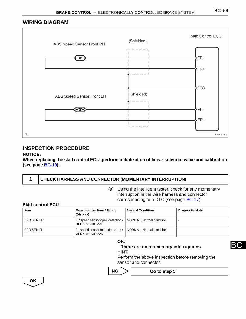
BRAKE CONTROL – ELECTRONICALLY CONTROLLED BRAKE SYSTEM BC–59
BC
WIRING DIAGRAM
INSPECTION PROCEDURENOTICE:When replacing the skid control ECU, perform initialization of linear solenoid valve and calibration (see page BC-19).
(a) Using the intelligent tester, check for any momentary interruption in the wire harness and connector corresponding to a DTC (see page BC-17).
Skid control ECU
OK:There are no momentary interruptions.
HINT:Perform the above inspection before removing the sensor and connector.
NG
OK
1 CHECK HARNESS AND CONNECTOR (MOMENTARY INTERRUPTION)
ABS Speed Sensor Front RH(Shielded)
Skid Control ECU
FR-
FR+
FSS
FL-
FR+
(Shielded)ABS Speed Sensor Front LH
C126244E01
Item Measurement Item / Range (Display)
Normal Condition Diagnostic Note
SPD SEN FR FR speed sensor open detection / OPEN or NORMAL
NORMAL: Normal condition -
SPD SEN FL FL speed sensor open detection / OPEN or NORMAL
NORMAL: Normal condition -
Go to step 5
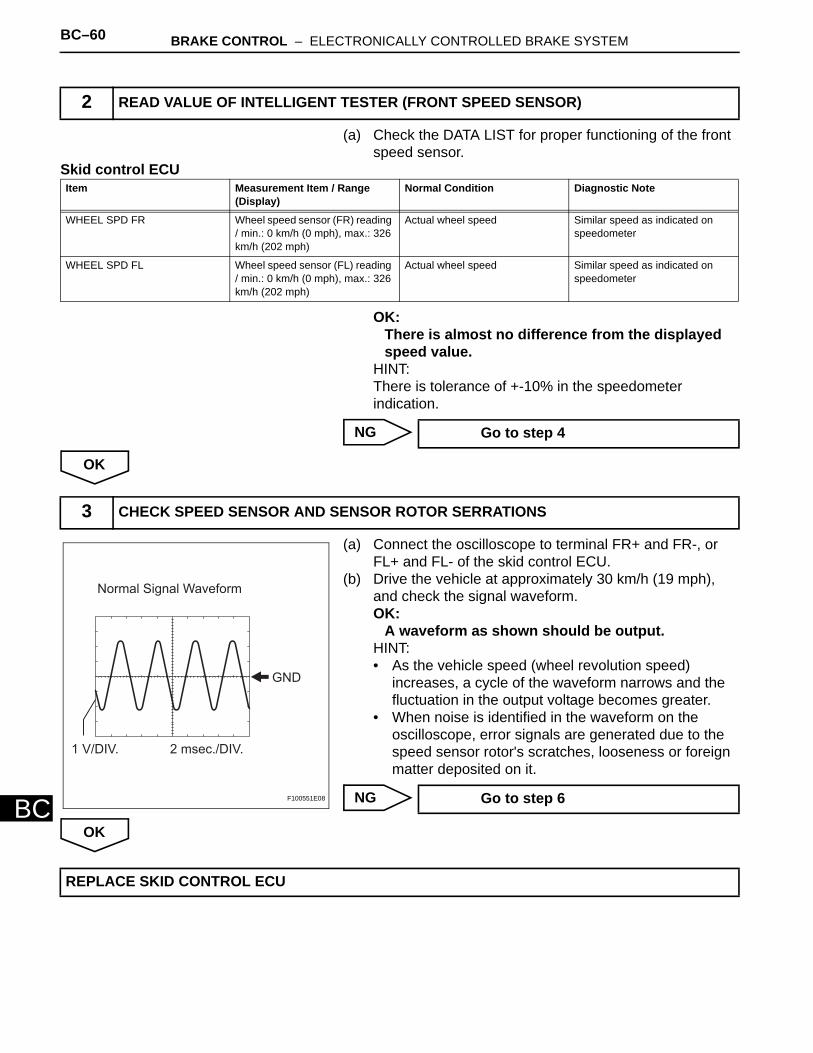
BC–60 BRAKE CONTROL – ELECTRONICALLY CONTROLLED BRAKE SYSTEM
BC
(a) Check the DATA LIST for proper functioning of the front speed sensor.
Skid control ECU
OK:There is almost no difference from the displayed speed value.
HINT:There is tolerance of +-10% in the speedometer indication.
NG
OK
(a) Connect the oscilloscope to terminal FR+ and FR-, or FL+ and FL- of the skid control ECU.
(b) Drive the vehicle at approximately 30 km/h (19 mph), and check the signal waveform.OK:
A waveform as shown should be output.HINT:• As the vehicle speed (wheel revolution speed)
increases, a cycle of the waveform narrows and the fluctuation in the output voltage becomes greater.
• When noise is identified in the waveform on the oscilloscope, error signals are generated due to the speed sensor rotor's scratches, looseness or foreign matter deposited on it.
NG
OK
2 READ VALUE OF INTELLIGENT TESTER (FRONT SPEED SENSOR)
Item Measurement Item / Range (Display)
Normal Condition Diagnostic Note
WHEEL SPD FR Wheel speed sensor (FR) reading / min.: 0 km/h (0 mph), max.: 326 km/h (202 mph)
Actual wheel speed Similar speed as indicated on speedometer
WHEEL SPD FL Wheel speed sensor (FL) reading / min.: 0 km/h (0 mph), max.: 326 km/h (202 mph)
Actual wheel speed Similar speed as indicated on speedometer
Go to step 4
3 CHECK SPEED SENSOR AND SENSOR ROTOR SERRATIONS
Normal Signal Waveform
GND
1 V/DIV. 2 msec./DIV.
F100551E08 Go to step 6
REPLACE SKID CONTROL ECU
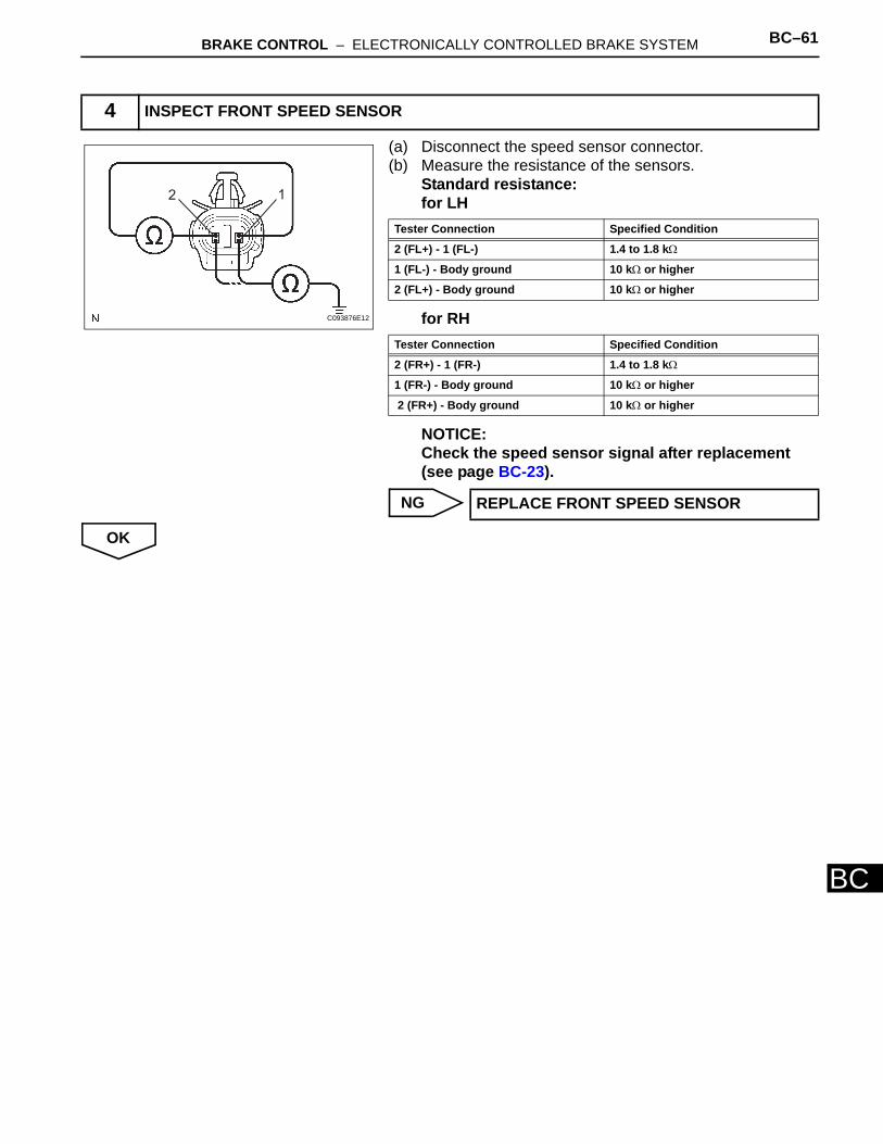
BRAKE CONTROL – ELECTRONICALLY CONTROLLED BRAKE SYSTEM BC–61
BC
(a) Disconnect the speed sensor connector. (b) Measure the resistance of the sensors.
Standard resistance:for LH
for RH
NOTICE:Check the speed sensor signal after replacement (see page BC-23).
NG
OK
4 INSPECT FRONT SPEED SENSOR
2 1
C093876E12
Tester Connection Specified Condition
2 (FL+) - 1 (FL-) 1.4 to 1.8 kΩ
1 (FL-) - Body ground 10 kΩ or higher
2 (FL+) - Body ground 10 kΩ or higher
Tester Connection Specified Condition
2 (FR+) - 1 (FR-) 1.4 to 1.8 kΩ
1 (FR-) - Body ground 10 kΩ or higher
2 (FR+) - Body ground 10 kΩ or higher
REPLACE FRONT SPEED SENSOR
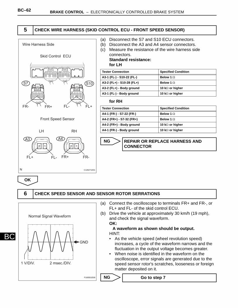
BC–62 BRAKE CONTROL – ELECTRONICALLY CONTROLLED BRAKE SYSTEM
BC
(a) Disconnect the S7 and S10 ECU connectors.(b) Disconnect the A3 and A4 sensor connectors.(c) Measure the resistance of the wire harness side
connectors.Standard resistance:for LH
for RH
NG
OK
(a) Connect the oscilloscope to terminals FR+ and FR-, or FL+ and FL- of the skid control ECU.
(b) Drive the vehicle at approximately 30 km/h (19 mph), and check the signal waveform.OK:
A waveform as shown should be output.HINT:• As the vehicle speed (wheel revolution speed)
increases, a cycle of the waveform narrows and the fluctuation in the output voltage becomes greater.
• When noise is identified in the waveform on the oscilloscope, error signals are generated due to the speed sensor rotor's scratches, looseness or foreign matter deposited on it.
NG
5 CHECK WIRE HARNESS (SKID CONTROL ECU - FRONT SPEED SENSOR)
Wire Harness Side
Skid Control ECU
FR- FR+ FL+
FL+ FL- FR+
FL-
FR-
A3 A4
S7 S10
Front Speed Sensor
LH RH
C126271E01
Tester Connection Specified Condition
A3-1 (FL-) - S10-22 (FL-) Below 1 Ω
A3-2 (FL+) - S10-28 (FL+) Below 1 Ω
A3-2 (FL+) - Body ground 10 kΩ or higher
A3-1 (FL-) - Body ground 10 kΩ or higher
Tester Connection Specified Condition
A4-1 (FR-) - S7-22 (FR-) Below 1 Ω
A4-2 (FR+) - S7-32 (FR+) Below 1 Ω
A4-2 (FR+) - Body ground 10 kΩ or higher
A4-1 (FR-) - Body ground 10 kΩ or higher
REPAIR OR REPLACE HARNESS AND CONNECTOR
6 CHECK SPEED SENSOR AND SENSOR ROTOR SERRATIONS
Normal Signal Waveform
GND
1 V/DIV. 2 msec./DIV.
F100551E09 Go to step 7
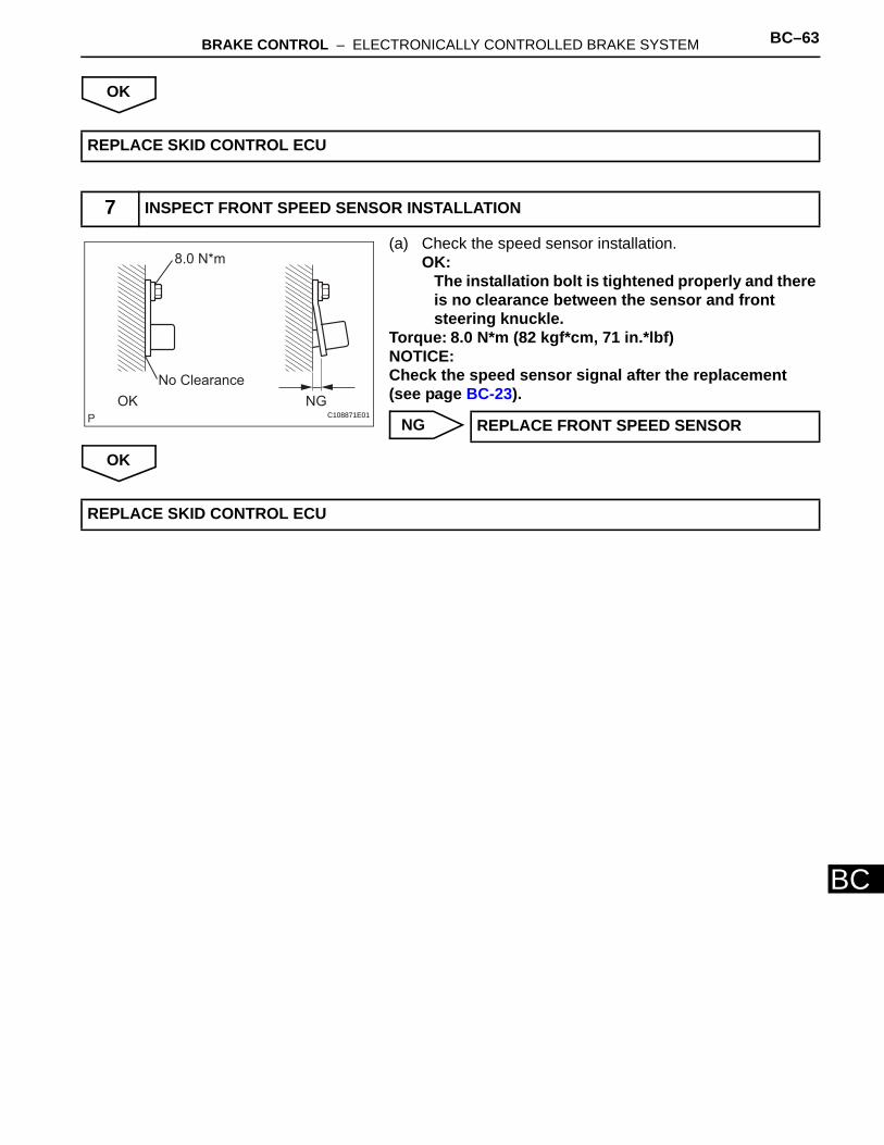
BRAKE CONTROL – ELECTRONICALLY CONTROLLED BRAKE SYSTEM BC–63
BC
OK
(a) Check the speed sensor installation.OK:
The installation bolt is tightened properly and there is no clearance between the sensor and front steering knuckle.
Torque: 8.0 N*m (82 kgf*cm, 71 in.*lbf)NOTICE:Check the speed sensor signal after the replacement (see page BC-23).
NG
OK
REPLACE SKID CONTROL ECU
7 INSPECT FRONT SPEED SENSOR INSTALLATION
8.0 N*m
No Clearance
OK NGC108871E01
REPLACE FRONT SPEED SENSOR
REPLACE SKID CONTROL ECU
BC–64 BRAKE CONTROL – ELECTRONICALLY CONTROLLED BRAKE SYSTEM
BC
DESCRIPTIONRefer to DTC C0200/31 and C0205/32 (see page BC-54).DTCs C1273/73 and C1274/74 can be deleted when the speed sensor sends a vehicle speed signal or the Test Mode ends. DTCs C1273/73 and C1274/74 are output only in the Test Mode.
DTC C0210/33 Rear Speed Sensor RH Circuit
DTC C0215/34 Rear Speed Sensor LH Circuit
DTC C1273/73 Low Output Signal of Rear Speed Sensor RH (Test Mode DTC)
DTC C1274/74 Low Output Signal of Rear Speed Sensor LH (Test Mode DTC)
DTC No. INF Code DTC Detection Condition Trouble Area
C0210/33 277278279280281282283284285286287288
When one of following conditions is met:• Speed of a malfunctioning
wheel is 0 mph (0 km/h) for at least 15 sec. when vehicle speed is 6 mph (10 km/h) or more.
• Speed of the slowest wheel is less than 1/7th of the 2nd slowest wheel for at least 15 sec. when vehicle speed is 6 mph (10 km/h) or more.
• Abnormal high wheel speed pulse is input for at least 15 sec.
• Abnormal high wheel speed pulse is input at least 7 times when ECU is on.
• Speed sensor pulse signal is instantly cut 7 times or more.
• Speed sensor signal line is open for at least 0.5 sec.
• Right rear and left rear speed sensor
• Each speed sensor circuit • Sensor rotor • Sensor installation• Skid control ECU
C0215/34 290291292293294295296297298299300301
When one of following conditions is met:• Speed of a malfunctioning
wheel is 0 mph (0 km/h) for at least 15 sec. when vehicle speed is 6 mph (10 km/h) or more.
• Speed of the slowest wheel is less than 1/7th of the 2nd slowest wheel for at least 15 sec. when vehicle speed is 6 mph (10 km/h) or more.
• Abnormal high wheel speed pulse is input for at least 15 sec.
• Abnormal high wheel speed pulse is input at least 7 times when ECU is on.
• Speed sensor pulse signal is instantly cut 7 times or more.
• Speed sensor signal line is open for at least 0.5 sec.
• Right rear and left rear speed sensor
• Each speed sensor circuit• Sensor rotor• Sensor installation• Skid control ECU
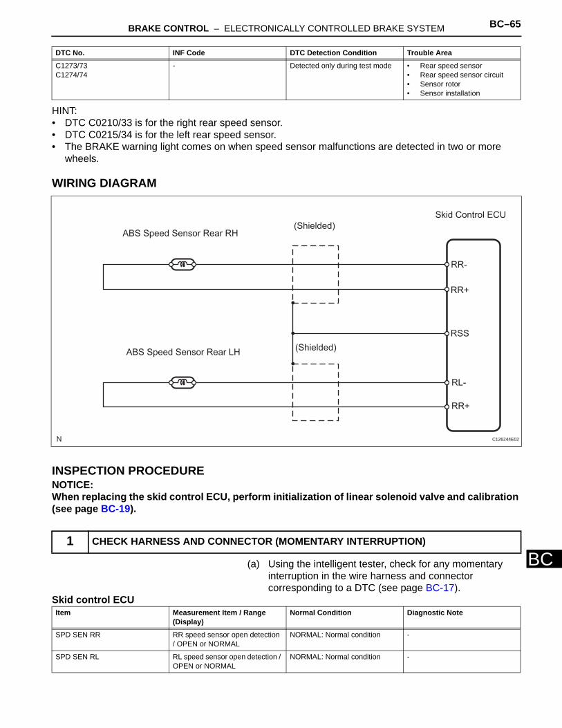
BRAKE CONTROL – ELECTRONICALLY CONTROLLED BRAKE SYSTEM BC–65
BC
HINT:• DTC C0210/33 is for the right rear speed sensor.• DTC C0215/34 is for the left rear speed sensor.• The BRAKE warning light comes on when speed sensor malfunctions are detected in two or more
wheels.
WIRING DIAGRAM
INSPECTION PROCEDURENOTICE:When replacing the skid control ECU, perform initialization of linear solenoid valve and calibration (see page BC-19).
(a) Using the intelligent tester, check for any momentary interruption in the wire harness and connector corresponding to a DTC (see page BC-17).
Skid control ECU
C1273/73C1274/74
- Detected only during test mode • Rear speed sensor• Rear speed sensor circuit• Sensor rotor • Sensor installation
1 CHECK HARNESS AND CONNECTOR (MOMENTARY INTERRUPTION)
DTC No. INF Code DTC Detection Condition Trouble Area
ABS Speed Sensor Rear RH(Shielded)
Skid Control ECU
RR-
RR+
RSS
RL-
RR+
(Shielded)ABS Speed Sensor Rear LH
C126244E02
Item Measurement Item / Range (Display)
Normal Condition Diagnostic Note
SPD SEN RR RR speed sensor open detection / OPEN or NORMAL
NORMAL: Normal condition -
SPD SEN RL RL speed sensor open detection / OPEN or NORMAL
NORMAL: Normal condition -
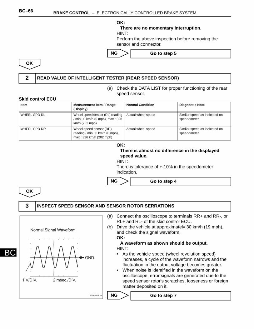
BC–66 BRAKE CONTROL – ELECTRONICALLY CONTROLLED BRAKE SYSTEM
BC
OK:There are no momentary interruption.
HINT:Perform the above inspection before removing the sensor and connector.
NG
OK
(a) Check the DATA LIST for proper functioning of the rear speed sensor.
Skid control ECU
OK:There is almost no difference in the displayed speed value.
HINT:There is tolerance of +-10% in the speedometer indication.
NG
OK
(a) Connect the oscilloscope to terminals RR+ and RR-, or RL+ and RL- of the skid control ECU.
(b) Drive the vehicle at approximately 30 km/h (19 mph), and check the signal waveform.OK:
A waveform as shown should be output.HINT:• As the vehicle speed (wheel revolution speed)
increases, a cycle of the waveform narrows and the fluctuation in the output voltage becomes greater.
• When noise is identified in the waveform on the oscilloscope, error signals are generated due to the speed sensor rotor's scratches, looseness or foreign matter deposited on it.
NG
Go to step 5
2 READ VALUE OF INTELLIGENT TESTER (REAR SPEED SENSOR)
Item Measurement Item / Range (Display)
Normal Condition Diagnostic Note
WHEEL SPD RL Wheel speed sensor (RL) reading / min.: 0 km/h (0 mph), max.: 326 km/h (202 mph)
Actual wheel speed Similar speed as indicated on speedometer
WHEEL SPD RR Wheel speed sensor (RR) reading / min.: 0 km/h (0 mph), max.: 326 km/h (202 mph)
Actual wheel speed Similar speed as indicated on speedometer
Go to step 4
3 INSPECT SPEED SENSOR AND SENSOR ROTOR SERRATIONS
Normal Signal Waveform
GND
1 V/DIV. 2 msec./DIV.
F100551E10 Go to step 7
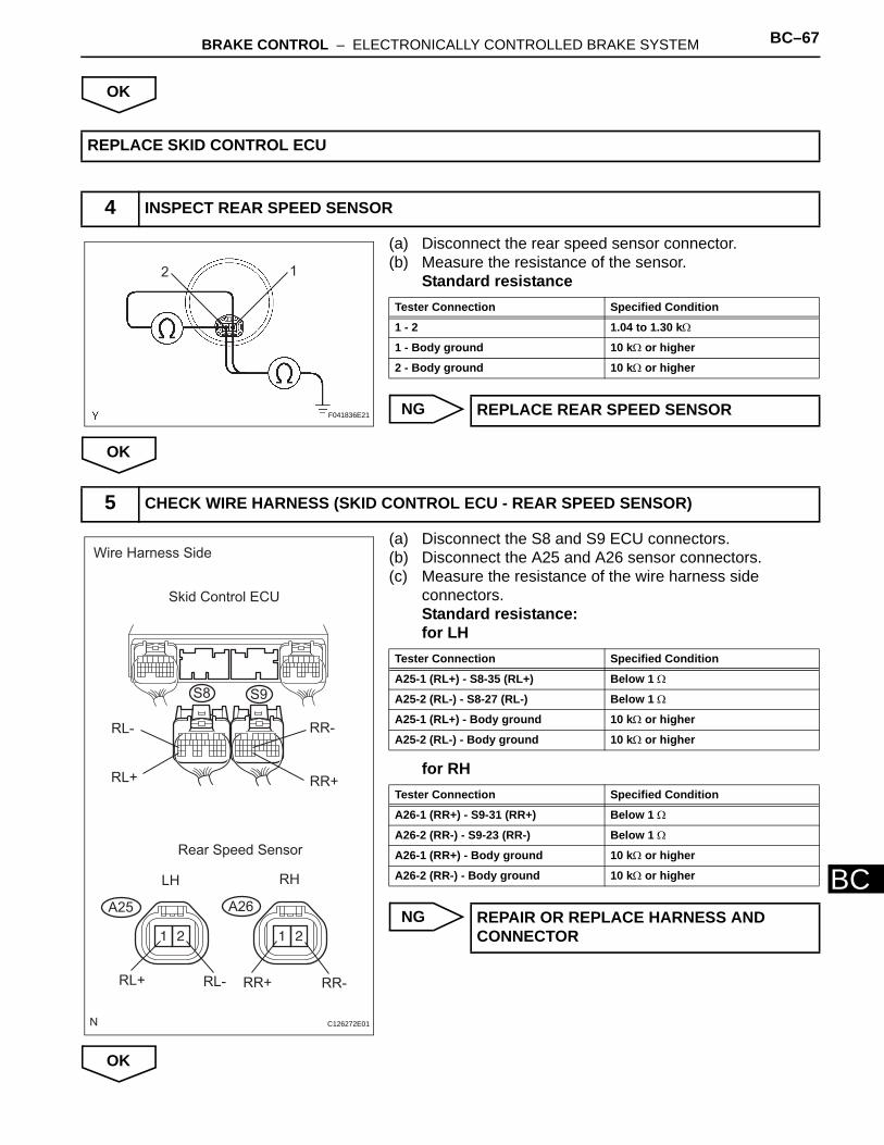
BRAKE CONTROL – ELECTRONICALLY CONTROLLED BRAKE SYSTEM BC–67
BC
OK
(a) Disconnect the rear speed sensor connector. (b) Measure the resistance of the sensor.
Standard resistance
NG
OK
(a) Disconnect the S8 and S9 ECU connectors.(b) Disconnect the A25 and A26 sensor connectors.(c) Measure the resistance of the wire harness side
connectors.Standard resistance:for LH
for RH
NG
OK
REPLACE SKID CONTROL ECU
4 INSPECT REAR SPEED SENSOR
2 1
F041836E21
Tester Connection Specified Condition
1 - 2 1.04 to 1.30 kΩ
1 - Body ground 10 kΩ or higher
2 - Body ground 10 kΩ or higher
REPLACE REAR SPEED SENSOR
5 CHECK WIRE HARNESS (SKID CONTROL ECU - REAR SPEED SENSOR)
Wire Harness Side
Skid Control ECU
Rear Speed Sensor
RL-
RL+
RR-
RR+
RL+ RL- RR-RR+
A25 A26
S8 S9
LH RH
C126272E01
Tester Connection Specified Condition
A25-1 (RL+) - S8-35 (RL+) Below 1 Ω
A25-2 (RL-) - S8-27 (RL-) Below 1 Ω
A25-1 (RL+) - Body ground 10 kΩ or higher
A25-2 (RL-) - Body ground 10 kΩ or higher
Tester Connection Specified Condition
A26-1 (RR+) - S9-31 (RR+) Below 1 Ω
A26-2 (RR-) - S9-23 (RR-) Below 1 Ω
A26-1 (RR+) - Body ground 10 kΩ or higher
A26-2 (RR-) - Body ground 10 kΩ or higher
REPAIR OR REPLACE HARNESS AND CONNECTOR
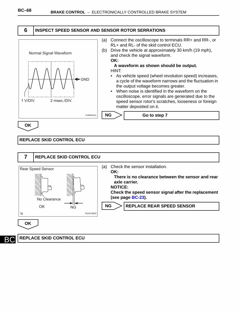
BC–68 BRAKE CONTROL – ELECTRONICALLY CONTROLLED BRAKE SYSTEM
BC
(a) Connect the oscilloscope to terminals RR+ and RR-, or RL+ and RL- of the skid control ECU.
(b) Drive the vehicle at approximately 30 km/h (19 mph), and check the signal waveform.OK:
A waveform as shown should be output.HINT:• As vehicle speed (wheel revolution speed) increases,
a cycle of the waveform narrows and the fluctuation in the output voltage becomes greater.
• When noise is identified in the waveform on the oscilloscope, error signals are generated due to the speed sensor rotor's scratches, looseness or foreign matter deposited on it.
NG
OK
(a) Check the sensor installation.OK:
There is no clearance between the sensor and rear axle carrier.
NOTICE:Check the speed sensor signal after the replacement (see page BC-23).
NG
OK
6 INSPECT SPEED SENSOR AND SENSOR ROTOR SERRATIONS
Normal Signal Waveform
GND
1 V/DIV. 2 msec./DIV.
F100551E11 Go to step 7
REPLACE SKID CONTROL ECU
7 REPLACE SKID CONTROL ECU
OK NG
Rear Speed Sensor
No Clearance
F010178E20
REPLACE REAR SPEED SENSOR
REPLACE SKID CONTROL ECU
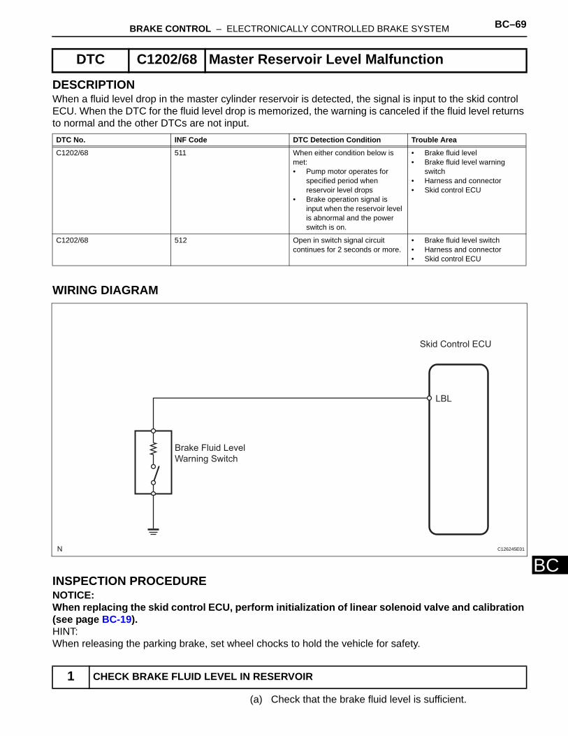
BRAKE CONTROL – ELECTRONICALLY CONTROLLED BRAKE SYSTEM BC–69
BC
DESCRIPTIONWhen a fluid level drop in the master cylinder reservoir is detected, the signal is input to the skid control ECU. When the DTC for the fluid level drop is memorized, the warning is canceled if the fluid level returns to normal and the other DTCs are not input.
WIRING DIAGRAM
INSPECTION PROCEDURENOTICE:When replacing the skid control ECU, perform initialization of linear solenoid valve and calibration (see page BC-19).HINT:When releasing the parking brake, set wheel chocks to hold the vehicle for safety.
(a) Check that the brake fluid level is sufficient.
DTC C1202/68 Master Reservoir Level Malfunction
DTC No. INF Code DTC Detection Condition Trouble Area
C1202/68 511 When either condition below is met:• Pump motor operates for
specified period when reservoir level drops
• Brake operation signal is input when the reservoir level is abnormal and the power switch is on.
• Brake fluid level• Brake fluid level warning
switch• Harness and connector• Skid control ECU
C1202/68 512 Open in switch signal circuit continues for 2 seconds or more.
• Brake fluid level switch • Harness and connector • Skid control ECU
1 CHECK BRAKE FLUID LEVEL IN RESERVOIR
Brake Fluid Level
Warning Switch
Skid Control ECU
LBL
C126245E01
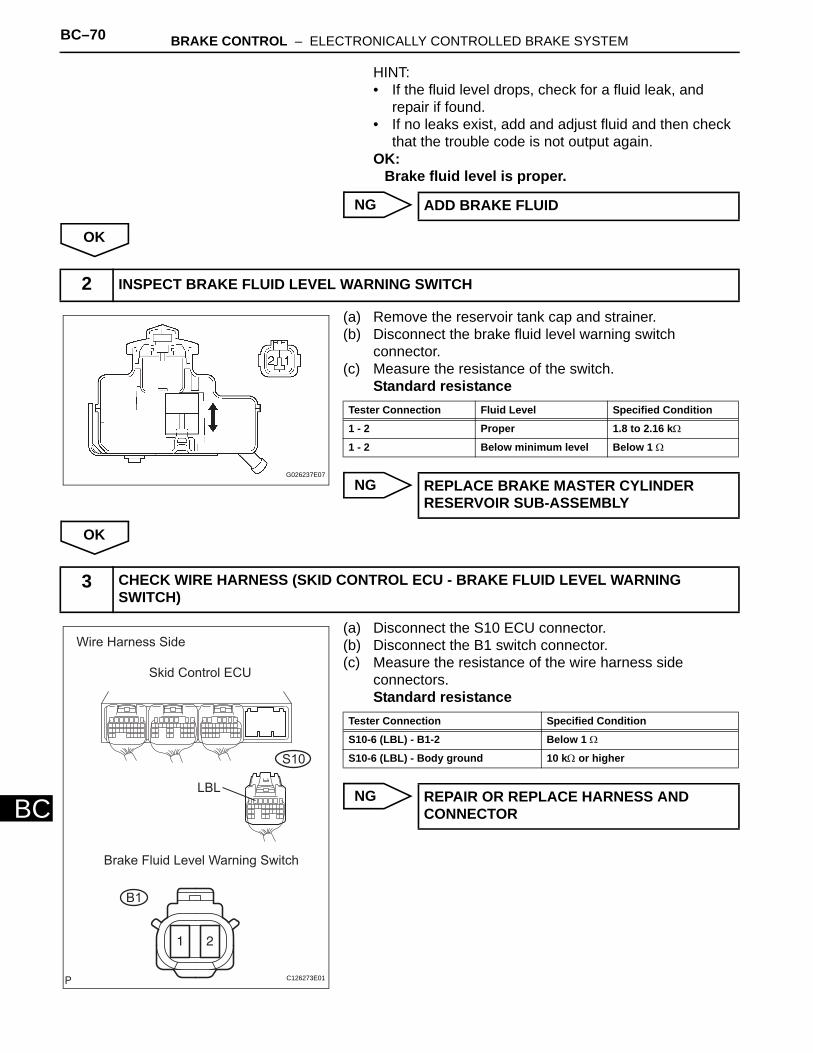
BC–70 BRAKE CONTROL – ELECTRONICALLY CONTROLLED BRAKE SYSTEM
BC
HINT:• If the fluid level drops, check for a fluid leak, and
repair if found. • If no leaks exist, add and adjust fluid and then check
that the trouble code is not output again.OK:
Brake fluid level is proper.
NG
OK
(a) Remove the reservoir tank cap and strainer. (b) Disconnect the brake fluid level warning switch
connector. (c) Measure the resistance of the switch.
Standard resistance
NG
OK
(a) Disconnect the S10 ECU connector. (b) Disconnect the B1 switch connector.(c) Measure the resistance of the wire harness side
connectors.Standard resistance
NG
ADD BRAKE FLUID
2 INSPECT BRAKE FLUID LEVEL WARNING SWITCH
G026237E07
Tester Connection Fluid Level Specified Condition
1 - 2 Proper 1.8 to 2.16 kΩ
1 - 2 Below minimum level Below 1 Ω
REPLACE BRAKE MASTER CYLINDER RESERVOIR SUB-ASSEMBLY
3 CHECK WIRE HARNESS (SKID CONTROL ECU - BRAKE FLUID LEVEL WARNING SWITCH)
Wire Harness Side
Skid Control ECU
LBL
Brake Fluid Level Warning Switch
B1
S10
C126273E01
Tester Connection Specified Condition
S10-6 (LBL) - B1-2 Below 1 Ω
S10-6 (LBL) - Body ground 10 kΩ or higher
REPAIR OR REPLACE HARNESS AND CONNECTOR
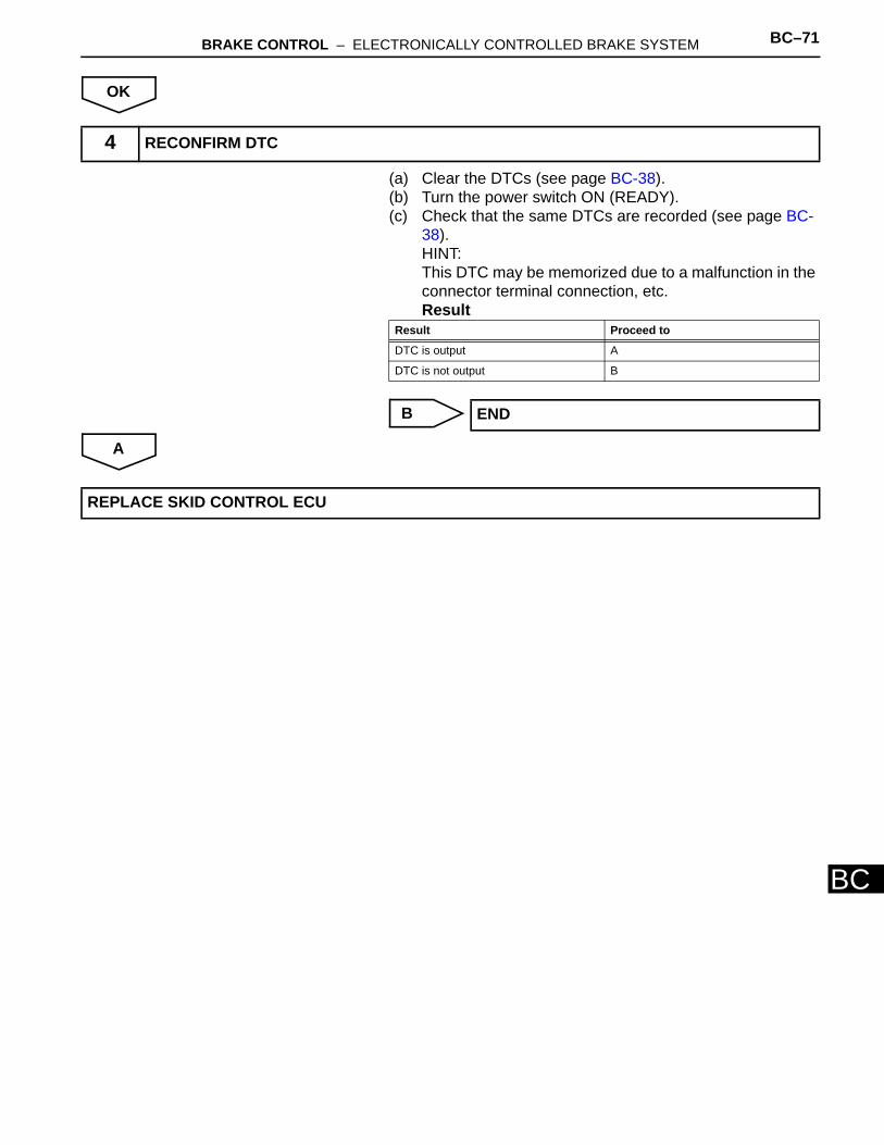
BRAKE CONTROL – ELECTRONICALLY CONTROLLED BRAKE SYSTEM BC–71
BC
OK
(a) Clear the DTCs (see page BC-38). (b) Turn the power switch ON (READY). (c) Check that the same DTCs are recorded (see page BC-
38).HINT:This DTC may be memorized due to a malfunction in the connector terminal connection, etc.Result
B
A
4 RECONFIRM DTC
Result Proceed to
DTC is output A
DTC is not output B
END
REPLACE SKID CONTROL ECU
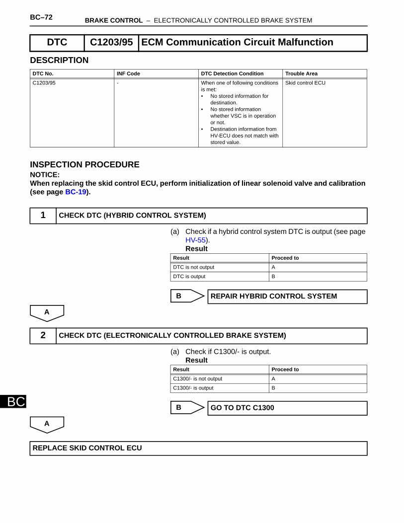
BC–72 BRAKE CONTROL – ELECTRONICALLY CONTROLLED BRAKE SYSTEM
BC
DESCRIPTION
INSPECTION PROCEDURENOTICE:When replacing the skid control ECU, perform initialization of linear solenoid valve and calibration (see page BC-19).
(a) Check if a hybrid control system DTC is output (see page HV-55).Result
B
A
(a) Check if C1300/- is output.Result
B
A
DTC C1203/95 ECM Communication Circuit Malfunction
DTC No. INF Code DTC Detection Condition Trouble Area
C1203/95 - When one of following conditions is met:• No stored information for
destination.• No stored information
whether VSC is in operation or not.
• Destination information from HV-ECU does not match with stored value.
Skid control ECU
1 CHECK DTC (HYBRID CONTROL SYSTEM)
Result Proceed to
DTC is not output A
DTC is output B
REPAIR HYBRID CONTROL SYSTEM
2 CHECK DTC (ELECTRONICALLY CONTROLLED BRAKE SYSTEM)
Result Proceed to
C1300/- is not output A
C1300/- is output B
GO TO DTC C1300
REPLACE SKID CONTROL ECU
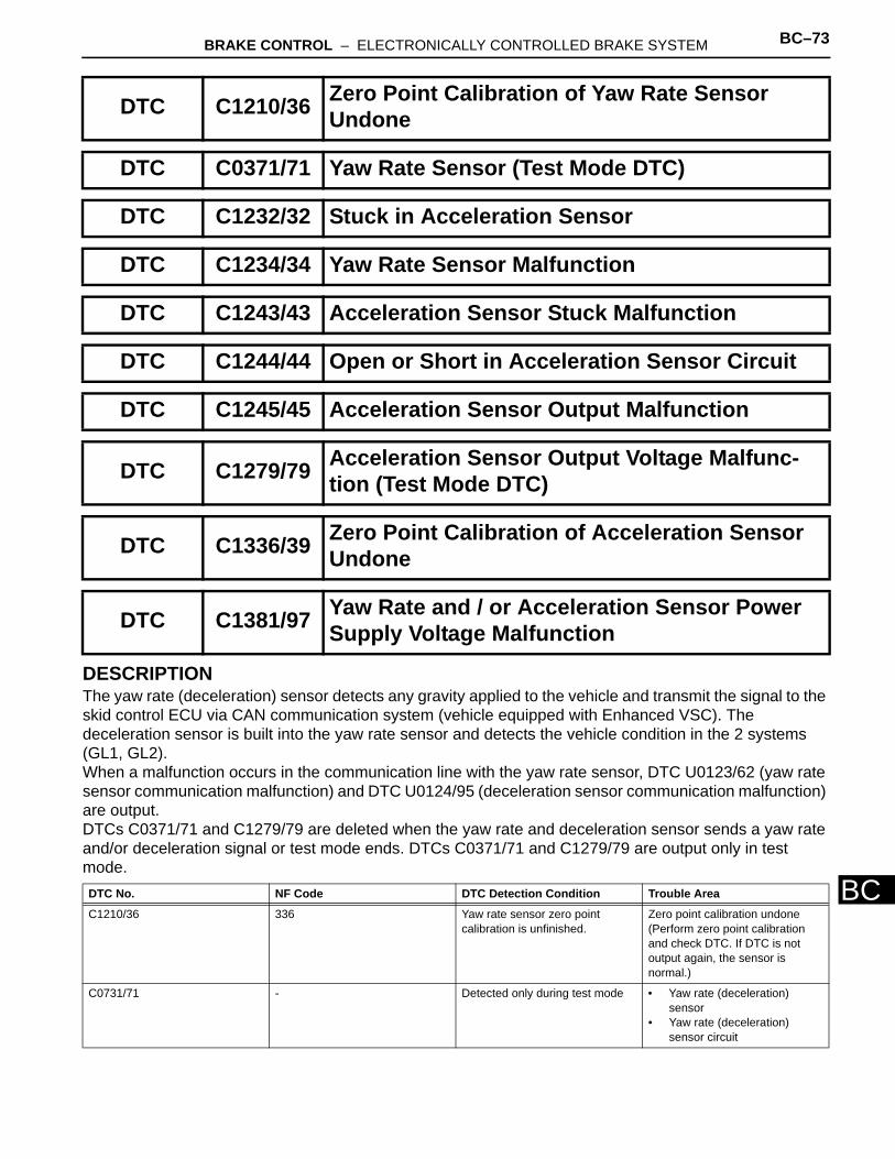
BRAKE CONTROL – ELECTRONICALLY CONTROLLED BRAKE SYSTEM BC–73
BC
DESCRIPTIONThe yaw rate (deceleration) sensor detects any gravity applied to the vehicle and transmit the signal to the skid control ECU via CAN communication system (vehicle equipped with Enhanced VSC). The deceleration sensor is built into the yaw rate sensor and detects the vehicle condition in the 2 systems (GL1, GL2). When a malfunction occurs in the communication line with the yaw rate sensor, DTC U0123/62 (yaw rate sensor communication malfunction) and DTC U0124/95 (deceleration sensor communication malfunction) are output.DTCs C0371/71 and C1279/79 are deleted when the yaw rate and deceleration sensor sends a yaw rate and/or deceleration signal or test mode ends. DTCs C0371/71 and C1279/79 are output only in test mode.
DTC C1210/36 Zero Point Calibration of Yaw Rate Sensor Undone
DTC C0371/71 Yaw Rate Sensor (Test Mode DTC)
DTC C1232/32 Stuck in Acceleration Sensor
DTC C1234/34 Yaw Rate Sensor Malfunction
DTC C1243/43 Acceleration Sensor Stuck Malfunction
DTC C1244/44 Open or Short in Acceleration Sensor Circuit
DTC C1245/45 Acceleration Sensor Output Malfunction
DTC C1279/79 Acceleration Sensor Output Voltage Malfunc-tion (Test Mode DTC)
DTC C1336/39 Zero Point Calibration of Acceleration Sensor Undone
DTC C1381/97 Yaw Rate and / or Acceleration Sensor Power Supply Voltage Malfunction
DTC No. NF Code DTC Detection Condition Trouble Area
C1210/36 336 Yaw rate sensor zero point calibration is unfinished.
Zero point calibration undone (Perform zero point calibration and check DTC. If DTC is not output again, the sensor is normal.)
C0731/71 - Detected only during test mode • Yaw rate (deceleration) sensor
• Yaw rate (deceleration) sensor circuit
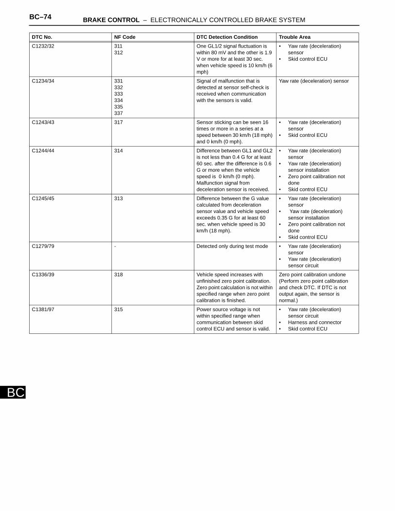
BC–74 BRAKE CONTROL – ELECTRONICALLY CONTROLLED BRAKE SYSTEM
BC
C1232/32 311312
One GL1/2 signal fluctuation is within 80 mV and the other is 1.9 V or more for at least 30 sec. when vehicle speed is 10 km/h (6 mph)
• Yaw rate (deceleration) sensor
• Skid control ECU
C1234/34 331332333334335337
Signal of malfunction that is detected at sensor self-check is received when communication with the sensors is valid.
Yaw rate (deceleration) sensor
C1243/43 317 Sensor sticking can be seen 16 times or more in a series at a speed between 30 km/h (18 mph) and 0 km/h (0 mph).
• Yaw rate (deceleration) sensor
• Skid control ECU
C1244/44 314 Difference between GL1 and GL2 is not less than 0.4 G for at least 60 sec. after the difference is 0.6 G or more when the vehicle speed is 0 km/h (0 mph).Malfunction signal from deceleration sensor is received.
• Yaw rate (deceleration) sensor
• Yaw rate (deceleration) sensor installation
• Zero point calibration not done
• Skid control ECU
C1245/45 313 Difference between the G value calculated from deceleration sensor value and vehicle speed exceeds 0.35 G for at least 60 sec. when vehicle speed is 30 km/h (18 mph).
• Yaw rate (deceleration) sensor
• Yaw rate (deceleration) sensor installation
• Zero point calibration not done
• Skid control ECU
C1279/79 - Detected only during test mode • Yaw rate (deceleration) sensor
• Yaw rate (deceleration) sensor circuit
C1336/39 318 Vehicle speed increases with unfinished zero point calibration.Zero point calculation is not within specified range when zero point calibration is finished.
Zero point calibration undone (Perform zero point calibration and check DTC. If DTC is not output again, the sensor is normal.)
C1381/97 315 Power source voltage is not within specified range when communication between skid control ECU and sensor is valid.
• Yaw rate (deceleration) sensor circuit
• Harness and connector• Skid control ECU
DTC No. NF Code DTC Detection Condition Trouble Area
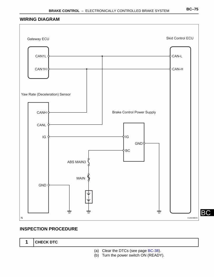
BRAKE CONTROL – ELECTRONICALLY CONTROLLED BRAKE SYSTEM BC–75
BC
WIRING DIAGRAM
INSPECTION PROCEDURE
(a) Clear the DTCs (see page BC-38).(b) Turn the power switch ON (READY).
1 CHECK DTC
Gateway ECU Skid Control ECU
CAN1L
CAN1H
CAN-L
CAN-H
Yaw Rate (Deceleration) Sensor
CANH
CANL
IG
Brake Control Power Supply
IG
BC
GND
ABS MAIN3
MAIN
GND
C126246E01
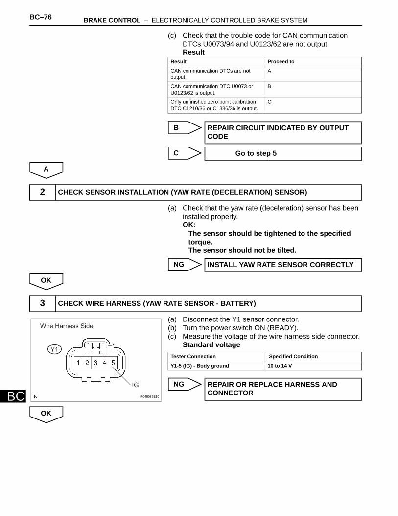
BC–76 BRAKE CONTROL – ELECTRONICALLY CONTROLLED BRAKE SYSTEM
BC
(c) Check that the trouble code for CAN communication DTCs U0073/94 and U0123/62 are not output.Result
B
C
A
(a) Check that the yaw rate (deceleration) sensor has been installed properly.OK:
The sensor should be tightened to the specified torque. The sensor should not be tilted.
NG
OK
(a) Disconnect the Y1 sensor connector.(b) Turn the power switch ON (READY).(c) Measure the voltage of the wire harness side connector.
Standard voltage
NG
OK
Result Proceed to
CAN communication DTCs are not output.
A
CAN communication DTC U0073 or U0123/62 is output.
B
Only unfinished zero point calibration DTC C1210/36 or C1336/36 is output.
C
REPAIR CIRCUIT INDICATED BY OUTPUT CODE
Go to step 5
2 CHECK SENSOR INSTALLATION (YAW RATE (DECELERATION) SENSOR)
INSTALL YAW RATE SENSOR CORRECTLY
3 CHECK WIRE HARNESS (YAW RATE SENSOR - BATTERY)
Y1
IG
Wire Harness Side
F045082E10
Tester Connection Specified Condition
Y1-5 (IG) - Body ground 10 to 14 V
REPAIR OR REPLACE HARNESS AND CONNECTOR
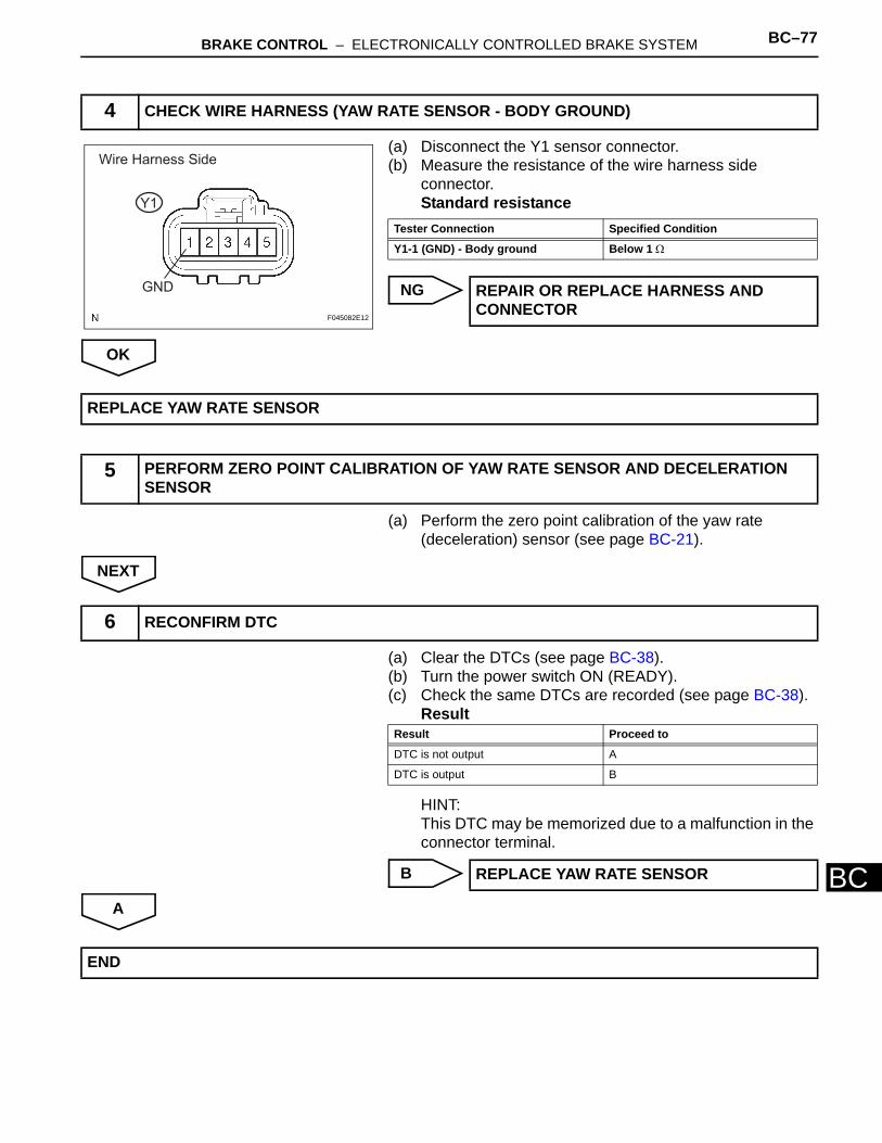
BRAKE CONTROL – ELECTRONICALLY CONTROLLED BRAKE SYSTEM BC–77
BC
(a) Disconnect the Y1 sensor connector.(b) Measure the resistance of the wire harness side
connector.Standard resistance
NG
OK
(a) Perform the zero point calibration of the yaw rate (deceleration) sensor (see page BC-21).
NEXT
(a) Clear the DTCs (see page BC-38). (b) Turn the power switch ON (READY). (c) Check the same DTCs are recorded (see page BC-38).
Result
HINT:This DTC may be memorized due to a malfunction in the connector terminal.
B
A
4 CHECK WIRE HARNESS (YAW RATE SENSOR - BODY GROUND)
Wire Harness Side
Y1
GND
F045082E12
Tester Connection Specified Condition
Y1-1 (GND) - Body ground Below 1 Ω
REPAIR OR REPLACE HARNESS AND CONNECTOR
REPLACE YAW RATE SENSOR
5 PERFORM ZERO POINT CALIBRATION OF YAW RATE SENSOR AND DECELERATION SENSOR
6 RECONFIRM DTC
Result Proceed to
DTC is not output A
DTC is output B
REPLACE YAW RATE SENSOR
END
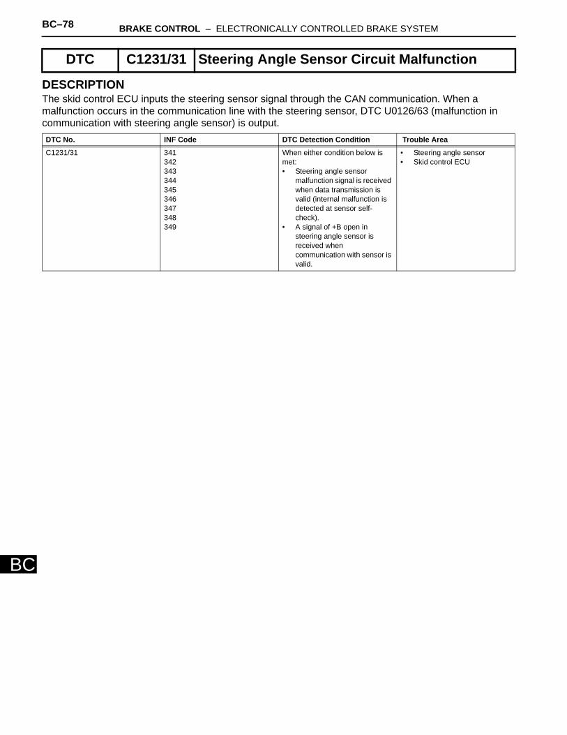
BC–78 BRAKE CONTROL – ELECTRONICALLY CONTROLLED BRAKE SYSTEM
BC
DESCRIPTIONThe skid control ECU inputs the steering sensor signal through the CAN communication. When a malfunction occurs in the communication line with the steering sensor, DTC U0126/63 (malfunction in communication with steering angle sensor) is output.
DTC C1231/31 Steering Angle Sensor Circuit Malfunction
DTC No. INF Code DTC Detection Condition Trouble Area
C1231/31 341342343344345346347348349
When either condition below is met:• Steering angle sensor
malfunction signal is received when data transmission is valid (internal malfunction is detected at sensor self-check).
• A signal of +B open in steering angle sensor is received when communication with sensor is valid.
• Steering angle sensor • Skid control ECU
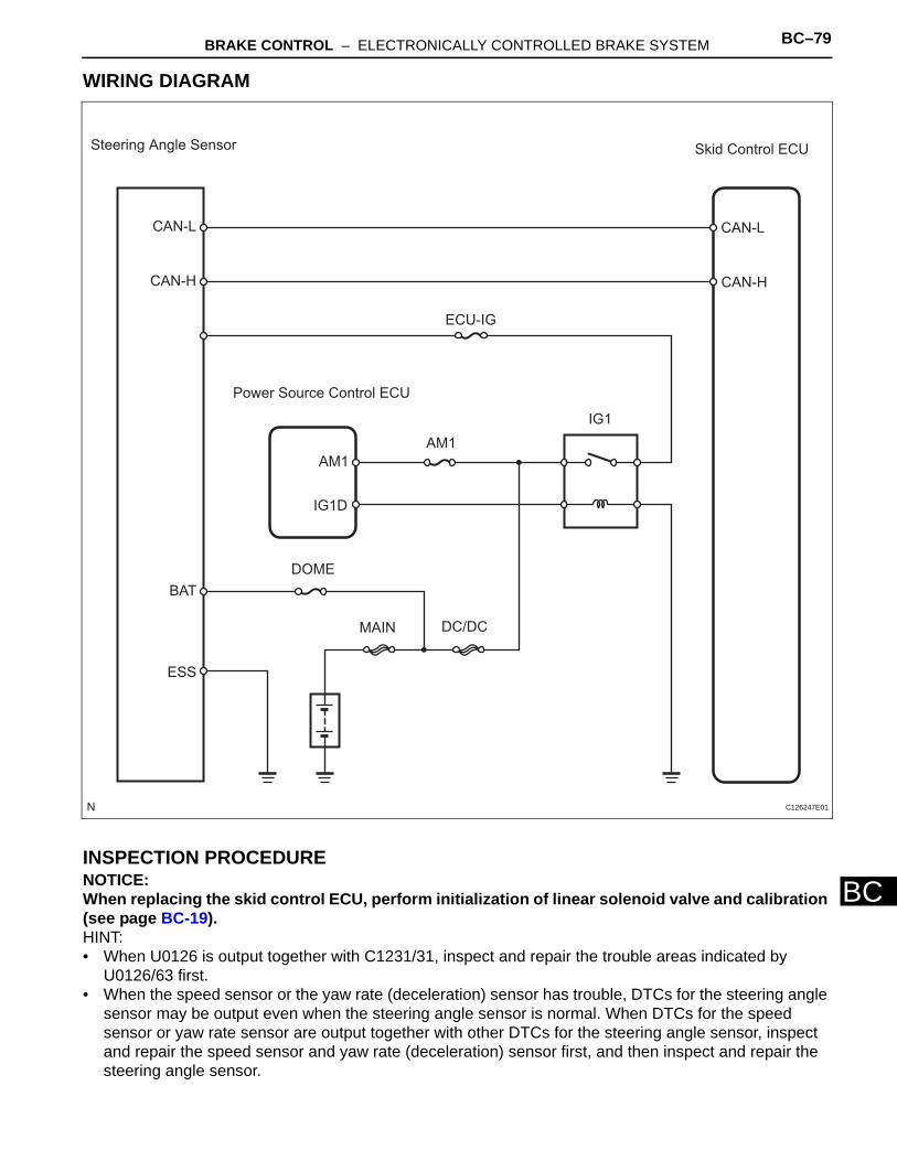
BRAKE CONTROL – ELECTRONICALLY CONTROLLED BRAKE SYSTEM BC–79
BC
WIRING DIAGRAM
INSPECTION PROCEDURENOTICE:When replacing the skid control ECU, perform initialization of linear solenoid valve and calibration (see page BC-19).HINT:• When U0126 is output together with C1231/31, inspect and repair the trouble areas indicated by
U0126/63 first. • When the speed sensor or the yaw rate (deceleration) sensor has trouble, DTCs for the steering angle
sensor may be output even when the steering angle sensor is normal. When DTCs for the speed sensor or yaw rate sensor are output together with other DTCs for the steering angle sensor, inspect and repair the speed sensor and yaw rate (deceleration) sensor first, and then inspect and repair the steering angle sensor.
Steering Angle Sensor Skid Control ECU
CAN-L
CAN-H
CAN-L
CAN-H
ECU-IG
IG1
AM1
Power Source Control ECU
AM1
IG1D
BAT
ESS
DOME
DC/DCMAIN
C126247E01
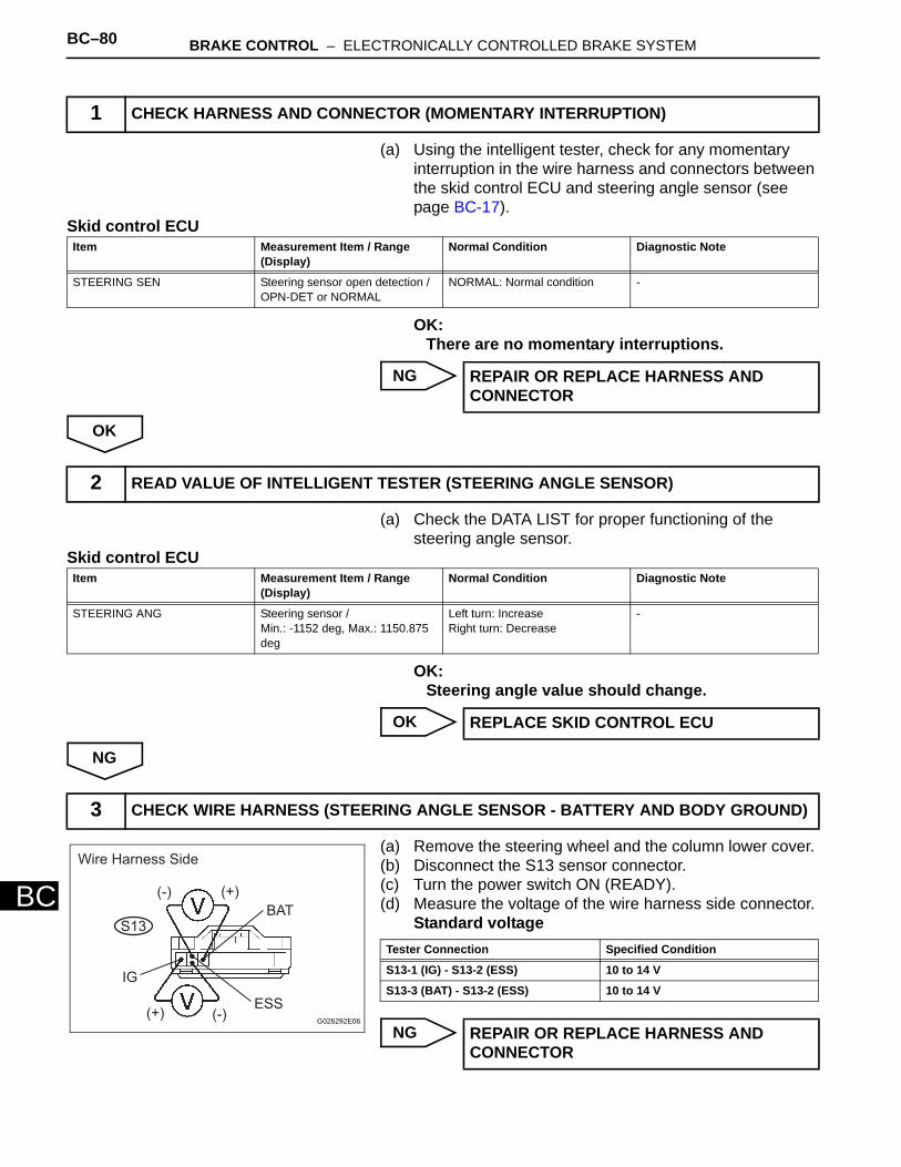
BC–80 BRAKE CONTROL – ELECTRONICALLY CONTROLLED BRAKE SYSTEM
BC
(a) Using the intelligent tester, check for any momentary interruption in the wire harness and connectors between the skid control ECU and steering angle sensor (see page BC-17).
Skid control ECU
OK:There are no momentary interruptions.
NG
OK
(a) Check the DATA LIST for proper functioning of the steering angle sensor.
Skid control ECU
OK:Steering angle value should change.
OK
NG
(a) Remove the steering wheel and the column lower cover. (b) Disconnect the S13 sensor connector. (c) Turn the power switch ON (READY). (d) Measure the voltage of the wire harness side connector.
Standard voltage
NG
1 CHECK HARNESS AND CONNECTOR (MOMENTARY INTERRUPTION)
Item Measurement Item / Range (Display)
Normal Condition Diagnostic Note
STEERING SEN Steering sensor open detection / OPN-DET or NORMAL
NORMAL: Normal condition -
REPAIR OR REPLACE HARNESS AND CONNECTOR
2 READ VALUE OF INTELLIGENT TESTER (STEERING ANGLE SENSOR)
Item Measurement Item / Range (Display)
Normal Condition Diagnostic Note
STEERING ANG Steering sensor / Min.: -1152 deg, Max.: 1150.875 deg
Left turn: Increase Right turn: Decrease
-
REPLACE SKID CONTROL ECU
3 CHECK WIRE HARNESS (STEERING ANGLE SENSOR - BATTERY AND BODY GROUND)
Wire Harness Side
(-) (+)
(+) (-)
IG
BAT
ESS
S13
G026292E06
Tester Connection Specified Condition
S13-1 (IG) - S13-2 (ESS) 10 to 14 V
S13-3 (BAT) - S13-2 (ESS) 10 to 14 V
REPAIR OR REPLACE HARNESS AND CONNECTOR
BRAKE CONTROL – ELECTRONICALLY CONTROLLED BRAKE SYSTEM BC–81
BC
OK
REPLACE STEERING ANGLE SENSOR
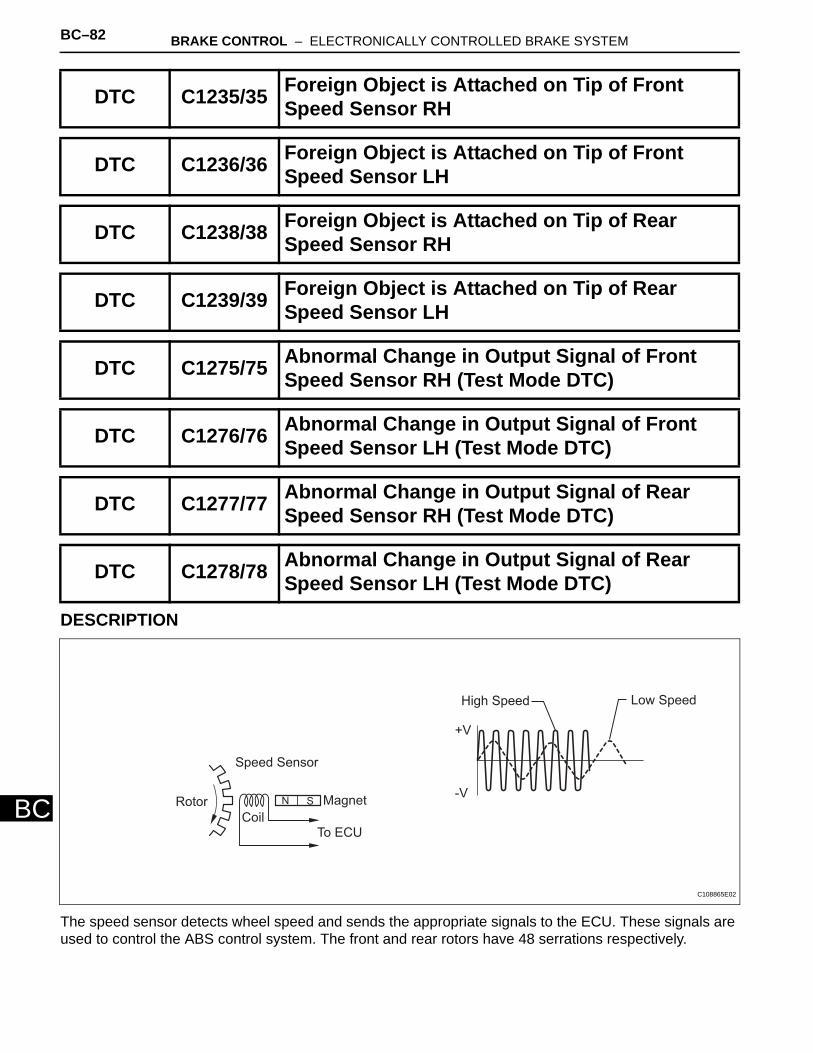
BC–82 BRAKE CONTROL – ELECTRONICALLY CONTROLLED BRAKE SYSTEM
BC
DESCRIPTION
The speed sensor detects wheel speed and sends the appropriate signals to the ECU. These signals are used to control the ABS control system. The front and rear rotors have 48 serrations respectively.
DTC C1235/35 Foreign Object is Attached on Tip of Front Speed Sensor RH
DTC C1236/36 Foreign Object is Attached on Tip of Front Speed Sensor LH
DTC C1238/38 Foreign Object is Attached on Tip of Rear Speed Sensor RH
DTC C1239/39 Foreign Object is Attached on Tip of Rear Speed Sensor LH
DTC C1275/75 Abnormal Change in Output Signal of Front Speed Sensor RH (Test Mode DTC)
DTC C1276/76 Abnormal Change in Output Signal of Front Speed Sensor LH (Test Mode DTC)
DTC C1277/77 Abnormal Change in Output Signal of Rear Speed Sensor RH (Test Mode DTC)
DTC C1278/78 Abnormal Change in Output Signal of Rear Speed Sensor LH (Test Mode DTC)
N SRotor
Speed Sensor
Magnet
To ECUCoil
+V
-V
High Speed Low Speed
C108865E02
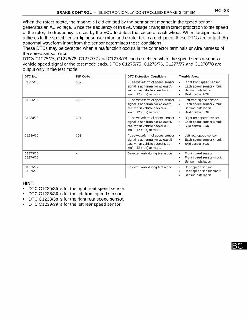
BRAKE CONTROL – ELECTRONICALLY CONTROLLED BRAKE SYSTEM BC–83
BC
When the rotors rotate, the magnetic field emitted by the permanent magnet in the speed sensor generates an AC voltage. Since the frequency of this AC voltage changes in direct proportion to the speed of the rotor, the frequency is used by the ECU to detect the speed of each wheel. When foreign matter adheres to the speed sensor tip or sensor rotor, or the rotor teeth are chipped, these DTCs are output. An abnormal waveform input from the sensor determines these conditions. These DTCs may be detected when a malfunction occurs in the connector terminals or wire harness of the speed sensor circuit.DTCs C1275/75, C1276/76, C1277/77 and C1278/78 can be deleted when the speed sensor sends a vehicle speed signal or the test mode ends. DTCs C1275/75, C1276/76, C1277/77 and C1278/78 are output only in the test mode.
HINT:• DTC C1235/35 is for the right front speed sensor. • DTC C1236/36 is for the left front speed sensor. • DTC C1238/38 is for the right rear speed sensor. • DTC C1239/39 is for the left rear speed sensor.
DTC No. INF Code DTC Detection Condition Trouble Area
C1235/35 302 Pulse waveform of speed sensor signal is abnormal for at least 5 sec. when vehicle speed is 20 km/h (12 mph) or more.
• Right front speed sensor• Each speed sensor circuit• Sensor installation• Skid control ECU
C1236/36 303 Pulse waveform of speed sensor signal is abnormal for at least 5 sec. when vehicle speed is 20 km/h (12 mph) or more.
• Left front speed sensor • Each speed sensor circuit • Sensor installation • Skid control ECU
C1238/38 304 Pulse waveform of speed sensor signal is abnormal for at least 5 sec. when vehicle speed is 20 km/h (12 mph) or more.
• Right rear speed sensor • Each speed sensor circuit • Skid control ECU
C1239/39 305 Pulse waveform of speed sensor signal is abnormal for at least 5 sec. when vehicle speed is 20 km/h (12 mph) or more.
• Left rear speed sensor• Each speed sensor circuit• Skid control ECU
C1275/75C1276/76
- Detected only during test mode • Front speed sensor• Front speed sensor circuit• Sensor installation
C1275/77C1276/78
- Detected only during test mode • Rear speed sensor• Rear speed sensor circuit• Sensor installation
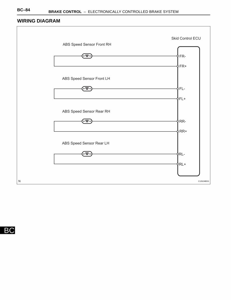
BC–84 BRAKE CONTROL – ELECTRONICALLY CONTROLLED BRAKE SYSTEM
BC
WIRING DIAGRAM
ABS Speed Sensor Front RH
ABS Speed Sensor Front LH
ABS Speed Sensor Rear RH
ABS Speed Sensor Rear LH
Skid Control ECU
FR-
FR+
FL-
FL+
RR-
RR+
RL-
RL+
C126248E01
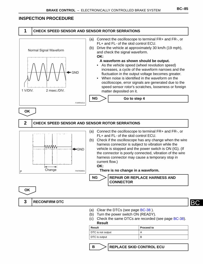
BRAKE CONTROL – ELECTRONICALLY CONTROLLED BRAKE SYSTEM BC–85
BC
INSPECTION PROCEDURE
(a) Connect the oscilloscope to terminal FR+ and FR-, or FL+ and FL- of the skid control ECU.
(b) Drive the vehicle at approximately 30 km/h (19 mph), and check the signal waveform.OK:
A waveform as shown should be output.• As the vehicle speed (wheel revolution speed)
increases, a cycle of the waveform narrows and the fluctuation in the output voltage becomes greater.
• When noise is identified in the waveform on the oscilloscope, error signals are generated due to the speed sensor rotor's scratches, looseness or foreign matter deposited on it.
NG
OK
(a) Connect the oscilloscope to terminal FR+ and FR-, or FL+ and FL- of the skid control ECU.
(b) Check if the oscilloscope has any change when the wire harness connector is subject to vibration while the vehicle is stopped and the power switch is ON (IG). (If the connector is poorly connected, vibration of the wire harness connector may cause a temporary stop in current flow.)OK:
There is no change in a waveform.
NG
OK
(a) Clear the DTCs (see page BC-38 ). (b) Turn the power switch ON (READY). (c) Check the same DTCs are recorded (see page BC-38).
Result
B
1 CHECK SPEED SENSOR AND SENSOR ROTOR SERRATIONS
Normal Signal Waveform
GND
1 V/DIV. 2 msec./DIV.
F100551E12
Go to step 4
2 CHECK SPEED SENSOR AND SENSOR ROTOR SERRATIONS
GND
Change F047503E01
REPAIR OR REPLACE HARNESS AND CONNECTOR
3 RECONFIRM DTC
Result Proceed to
DTC is not output A
DTC is output B
REPLACE SKID CONTROL ECU
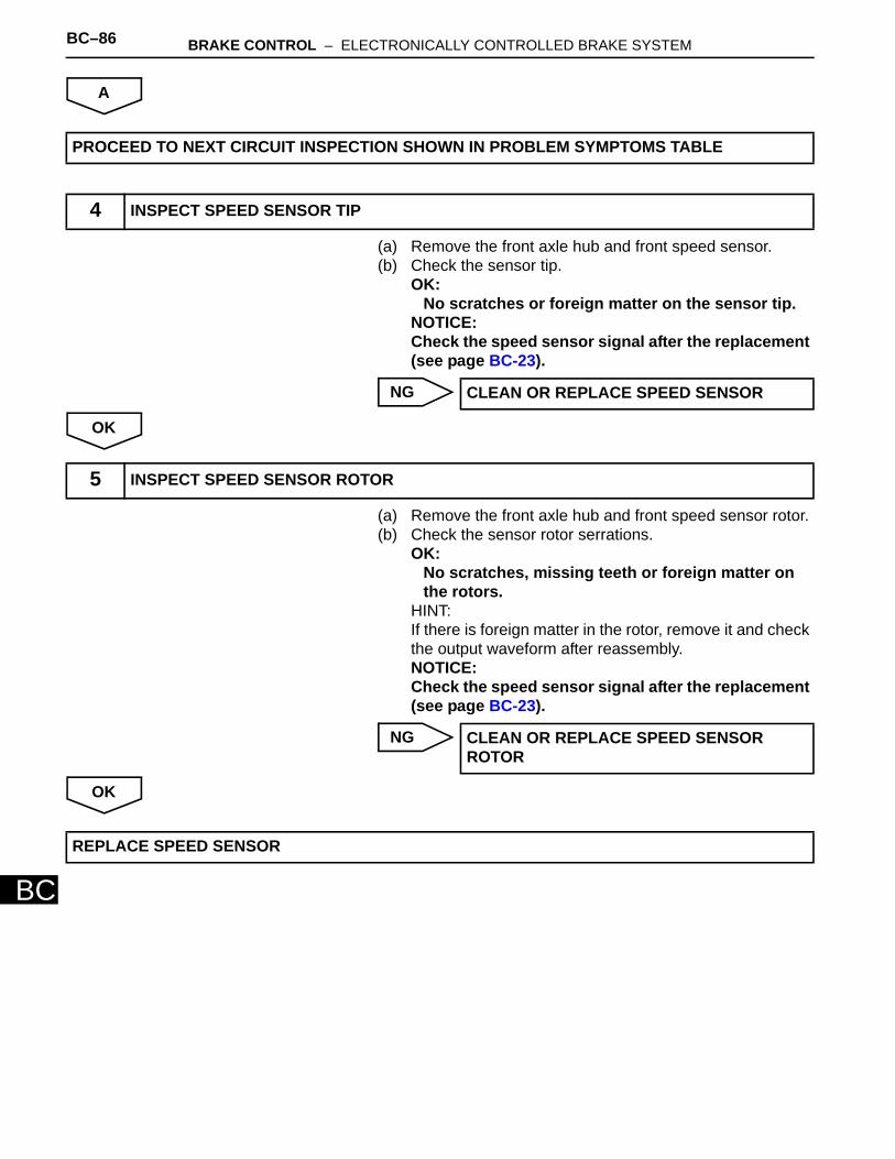
BC–86 BRAKE CONTROL – ELECTRONICALLY CONTROLLED BRAKE SYSTEM
BC
A
(a) Remove the front axle hub and front speed sensor. (b) Check the sensor tip.
OK:No scratches or foreign matter on the sensor tip.
NOTICE:Check the speed sensor signal after the replacement (see page BC-23).
NG
OK
(a) Remove the front axle hub and front speed sensor rotor. (b) Check the sensor rotor serrations.
OK:No scratches, missing teeth or foreign matter on the rotors.
HINT:If there is foreign matter in the rotor, remove it and check the output waveform after reassembly.NOTICE:Check the speed sensor signal after the replacement (see page BC-23).
NG
OK
PROCEED TO NEXT CIRCUIT INSPECTION SHOWN IN PROBLEM SYMPTOMS TABLE
4 INSPECT SPEED SENSOR TIP
CLEAN OR REPLACE SPEED SENSOR
5 INSPECT SPEED SENSOR ROTOR
CLEAN OR REPLACE SPEED SENSOR ROTOR
REPLACE SPEED SENSOR
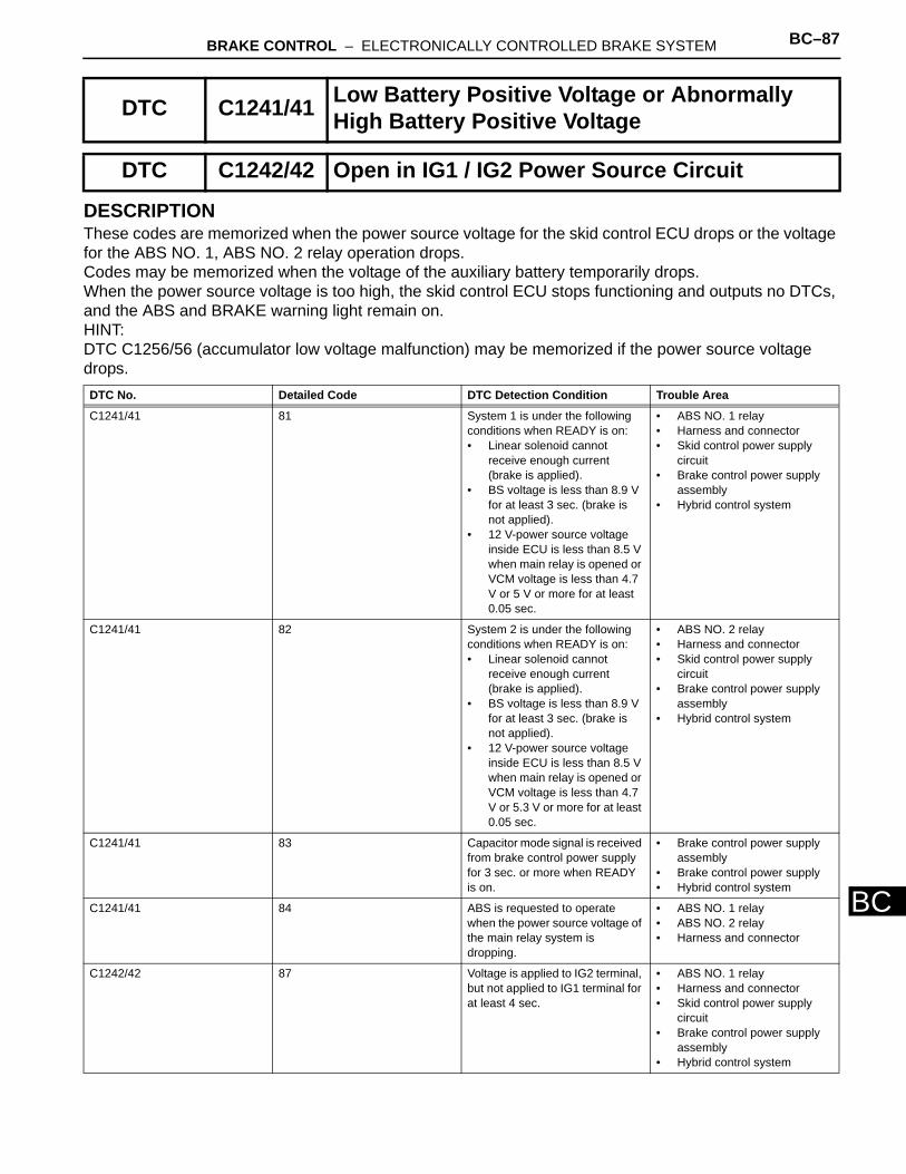
BRAKE CONTROL – ELECTRONICALLY CONTROLLED BRAKE SYSTEM BC–87
BC
DESCRIPTIONThese codes are memorized when the power source voltage for the skid control ECU drops or the voltage for the ABS NO. 1, ABS NO. 2 relay operation drops. Codes may be memorized when the voltage of the auxiliary battery temporarily drops. When the power source voltage is too high, the skid control ECU stops functioning and outputs no DTCs, and the ABS and BRAKE warning light remain on.HINT:DTC C1256/56 (accumulator low voltage malfunction) may be memorized if the power source voltage drops.
DTC C1241/41 Low Battery Positive Voltage or Abnormally High Battery Positive Voltage
DTC C1242/42 Open in IG1 / IG2 Power Source Circuit
DTC No. Detailed Code DTC Detection Condition Trouble Area
C1241/41 81 System 1 is under the following conditions when READY is on:• Linear solenoid cannot
receive enough current (brake is applied).
• BS voltage is less than 8.9 V for at least 3 sec. (brake is not applied).
• 12 V-power source voltage inside ECU is less than 8.5 V when main relay is opened or VCM voltage is less than 4.7 V or 5 V or more for at least 0.05 sec.
• ABS NO. 1 relay • Harness and connector • Skid control power supply
circuit • Brake control power supply
assembly• Hybrid control system
C1241/41 82 System 2 is under the following conditions when READY is on:• Linear solenoid cannot
receive enough current (brake is applied).
• BS voltage is less than 8.9 V for at least 3 sec. (brake is not applied).
• 12 V-power source voltage inside ECU is less than 8.5 V when main relay is opened or VCM voltage is less than 4.7 V or 5.3 V or more for at least 0.05 sec.
• ABS NO. 2 relay • Harness and connector • Skid control power supply
circuit • Brake control power supply
assembly • Hybrid control system
C1241/41 83 Capacitor mode signal is received from brake control power supply for 3 sec. or more when READY is on.
• Brake control power supply assembly
• Brake control power supply • Hybrid control system
C1241/41 84 ABS is requested to operate when the power source voltage of the main relay system is dropping.
• ABS NO. 1 relay • ABS NO. 2 relay • Harness and connector
C1242/42 87 Voltage is applied to IG2 terminal, but not applied to IG1 terminal for at least 4 sec.
• ABS NO. 1 relay • Harness and connector • Skid control power supply
circuit • Brake control power supply
assembly • Hybrid control system
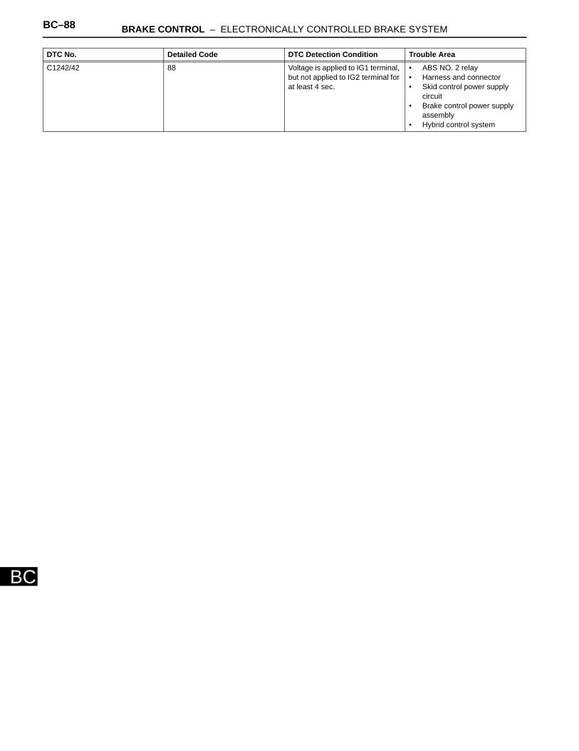
BC–88 BRAKE CONTROL – ELECTRONICALLY CONTROLLED BRAKE SYSTEM
BC
C1242/42 88 Voltage is applied to IG1 terminal, but not applied to IG2 terminal for at least 4 sec.
• ABS NO. 2 relay • Harness and connector • Skid control power supply
circuit • Brake control power supply
assembly • Hybrid control system
DTC No. Detailed Code DTC Detection Condition Trouble Area
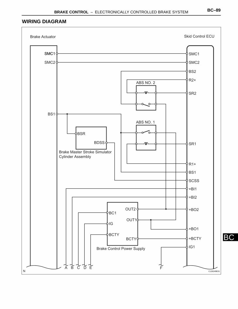
BRAKE CONTROL – ELECTRONICALLY CONTROLLED BRAKE SYSTEM BC–89
BC
WIRING DIAGRAM
Brake Actuator Skid Control ECU
SMC1
SMC2
BS1
SMC1
SMC2
SMC1
BS2
R2+
SR2
ABS NO. 2
ABS NO. 1
SR1
Brake Master Stroke Simulator
Cylinder Assembly
BSR
BDSS
R1+
BS1
SCSS
+BO2
+BO1
+BI1
+BI2
+BCTY
IG1Brake Control Power Supply
BC1
IG
BCTY
OUT2
OUT1
BCTY
A B C D E FC126249E01
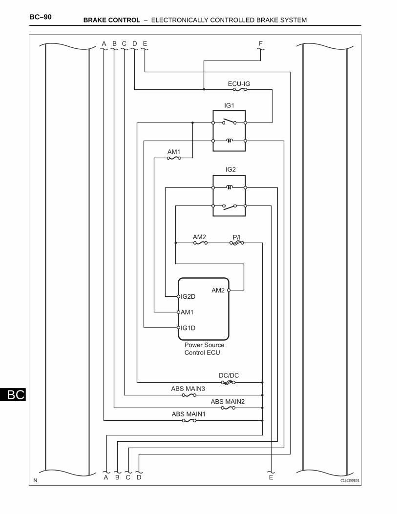
BC–90 BRAKE CONTROL – ELECTRONICALLY CONTROLLED BRAKE SYSTEM
BC
A B C D E F
ECU-IG
IG1
AM1
IG2
Power Source
Control ECU
AM2IG2D
AM1
IG1D
AM2 P/I
DC/DC
ABS MAIN3
ABS MAIN2
ABS MAIN1
A B C D E C126250E01
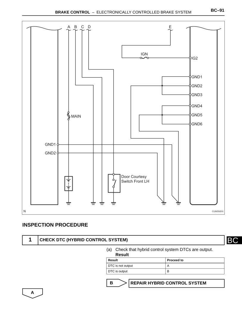
BRAKE CONTROL – ELECTRONICALLY CONTROLLED BRAKE SYSTEM BC–91
BC
INSPECTION PROCEDURE
(a) Check that hybrid control system DTCs are output.Result
B
A
1 CHECK DTC (HYBRID CONTROL SYSTEM)
A B C D E
IGNIG2
GND1
GND2
GND3
GND4
GND5
GND6
MAIN
GND1
GND2
Door Courtesy
Switch Front LH
C126251E01
Result Proceed to
DTC is not output A
DTC is output B
REPAIR HYBRID CONTROL SYSTEM
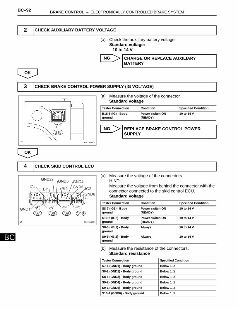
BC–92 BRAKE CONTROL – ELECTRONICALLY CONTROLLED BRAKE SYSTEM
BC
(a) Check the auxiliary battery voltage.Standard voltage:
10 to 14 V
NG
OK
(a) Measure the voltage of the connector.Standard voltage
NG
OK
(a) Measure the voltage of the connectors.HINT:Measure the voltage from behind the connector with the connector connected to the skid control ECU.Standard voltage
(b) Measure the resistance of the connectors.Standard resistance
2 CHECK AUXILIARY BATTERY VOLTAGE
CHARGE OR REPLACE AUXILIARY BATTERY
3 CHECK BRAKE CONTROL POWER SUPPLY (IG VOLTAGE)
IG
B18
F047500E01
Tester Connection Condition Specified Condition
B18-5 (IG) - Body ground
Power switch ON (READY)
10 to 14 V
REPLACE BRAKE CONTROL POWER SUPPLY
4 CHECK SKID CONTROL ECU
GND1
IG1+BI1
GND2GND3
+BI2
S7 S8 S9 S10
GND6
IG2GND5
GND4
F047485E54
Tester Connection Condition Specified Condition
S8-7 (IG1) - Body ground
Power switch ON (READY)
10 to 14 V
S10-5 (IG2) - Body ground
Power switch ON (READY)
10 to 14 V
S8-3 (+BI1) - Body ground
Always 10 to 14 V
S9-5 (+BI2) - Body ground
Always 10 to 14 V
Tester Connection Specified Condition
S7-1 (GND1) - Body ground Below 1 Ω
S8-2 (GND2) - Body ground Below 1 Ω
S8-1 (GND3) - Body ground Below 1 Ω
S9-2 (GND4) - Body ground Below 1 Ω
S9-1 (GND5) - Body ground Below 1 Ω
S10-4 (GND6) - Body ground Below 1 Ω
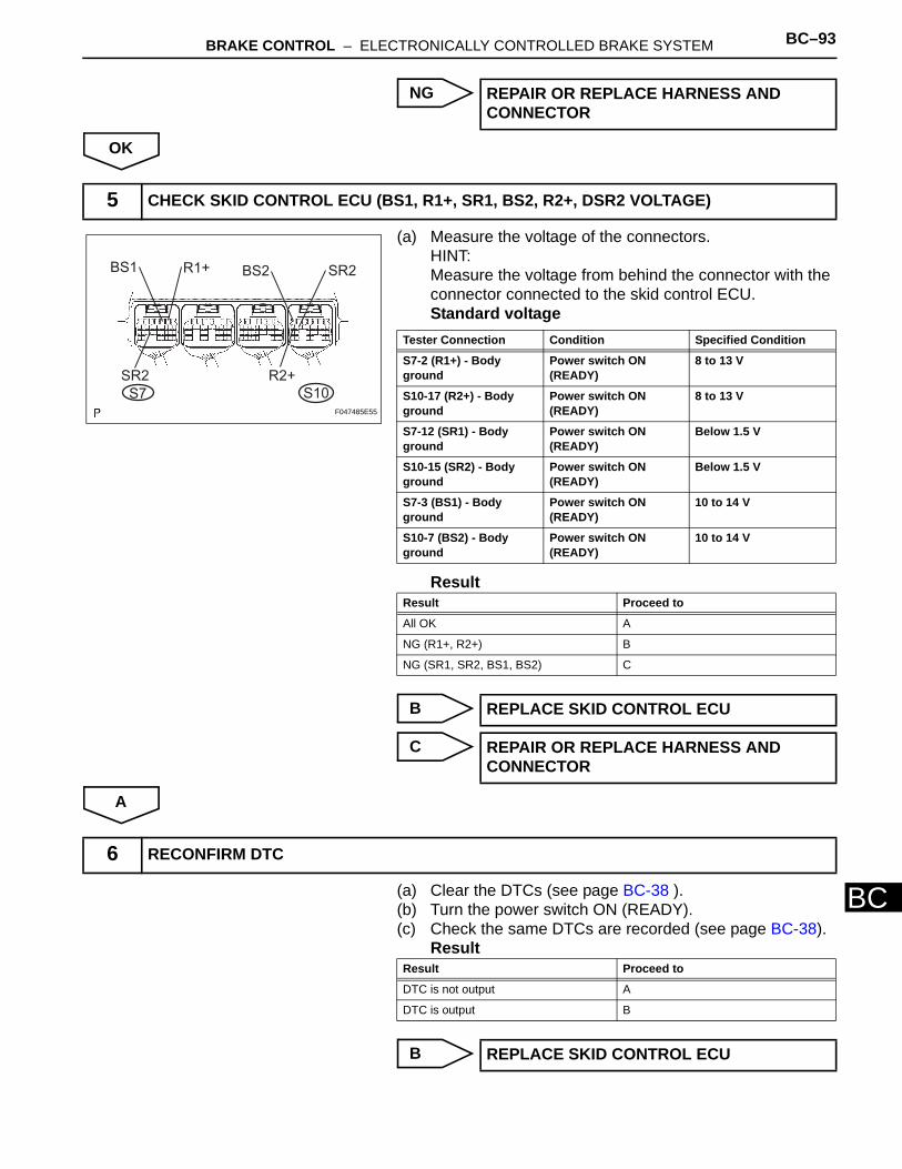
BRAKE CONTROL – ELECTRONICALLY CONTROLLED BRAKE SYSTEM BC–93
BC
NG
OK
(a) Measure the voltage of the connectors.HINT:Measure the voltage from behind the connector with the connector connected to the skid control ECU.Standard voltage
Result
B
C
A
(a) Clear the DTCs (see page BC-38 ). (b) Turn the power switch ON (READY). (c) Check the same DTCs are recorded (see page BC-38).
Result
B
REPAIR OR REPLACE HARNESS AND CONNECTOR
5 CHECK SKID CONTROL ECU (BS1, R1+, SR1, BS2, R2+, DSR2 VOLTAGE)
BS1 R1+ BS2 SR2
R2+SR2
S7 S10F047485E55
Tester Connection Condition Specified Condition
S7-2 (R1+) - Body ground
Power switch ON (READY)
8 to 13 V
S10-17 (R2+) - Body ground
Power switch ON (READY)
8 to 13 V
S7-12 (SR1) - Body ground
Power switch ON (READY)
Below 1.5 V
S10-15 (SR2) - Body ground
Power switch ON (READY)
Below 1.5 V
S7-3 (BS1) - Body ground
Power switch ON (READY)
10 to 14 V
S10-7 (BS2) - Body ground
Power switch ON (READY)
10 to 14 V
Result Proceed to
All OK A
NG (R1+, R2+) B
NG (SR1, SR2, BS1, BS2) C
REPLACE SKID CONTROL ECU
REPAIR OR REPLACE HARNESS AND CONNECTOR
6 RECONFIRM DTC
Result Proceed to
DTC is not output A
DTC is output B
REPLACE SKID CONTROL ECU
BC–94 BRAKE CONTROL – ELECTRONICALLY CONTROLLED BRAKE SYSTEM
BC
A
END (DTC MAY BE STORED DUE TO TEMPORARY POWER SOURCE VOLTAGE DROP)
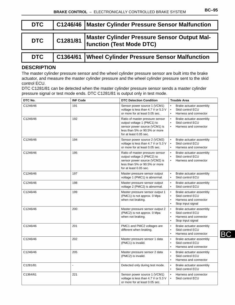
BRAKE CONTROL – ELECTRONICALLY CONTROLLED BRAKE SYSTEM BC–95
BC
DESCRIPTIONThe master cylinder pressure sensor and the wheel cylinder pressure sensor are built into the brake actuator, and measure the master cylinder pressure and the wheel cylinder pressure sent to the skid control ECU.DTC C1281/81 can be detected when the master cylinder pressure sensor sends a master cylinder pressure signal or test mode ends. DTC C1281/81 is output only in test mode.
DTC C1246/46 Master Cylinder Pressure Sensor Malfunction
DTC C1281/81 Master Cylinder Pressure Sensor Output Mal-function (Test Mode DTC)
DTC C1364/61 Wheel Cylinder Pressure Sensor Malfunction
DTC No. INF Code DTC Detection Condition Trouble Area
C1246/46 191 Sensor power source 1 (VCM1) voltage is less than 4.7 V or 5.3 V or more for at least 0.05 sec.
• Brake actuator assembly • Skid control ECU • Harness and connector
C1246/46 192 Ratio of master pressure sensor output voltage 1 (PMC1) to sensor power source (VCM1) is less than 5% or 90.5% or more for at least 0.05 sec.
• Brake actuator assembly • Skid control ECU • Harness and connector
C1246/46 194 Sensor power source 2 (VCM2) voltage is less than 4.7 V or 5.3 V or more for at least 0.05 sec.
• Brake actuator assembly • Skid control ECU • Harness and connector
C1246/46 195 Ratio of master pressure sensor output voltage 2 (PMC2) to sensor power source (VCM2) is less than 5% or 90.5% or more for at least 0.05 sec.
• Brake actuator assembly • Skid control ECU • Harness and connector
C1246/46 197 Master pressure sensor output voltage 1 (PMC1) is abnormal.
• Brake actuator assembly • Skid control ECU
C1246/46 198 Master pressure sensor output voltage 2 (PMC2) is abnormal.
• Brake actuator assembly • Skid control ECU
C1246/46 199 Master pressure sensor output 1 (PMC1) is not approx. 0 Mpa when not braking.
• Brake actuator assembly • Skid control ECU • Harness and connector • Stop input signal
C1246/46 200 Master pressure sensor output 2 (PMC2) is not approx. 0 Mpa when not braking.
• Brake actuator assembly • Skid control ECU • Harness and connector • Stop input signal
C1246/46 201 PMC1 and PMC2 voltages are different when braking.
• Brake actuator assembly • Skid control ECU • Harness and connector
C1246/46 202 Master pressure sensor 1 data (PMC1) is invalid.
• Brake actuator assembly • Skid control ECU • Harness and connector
C1246/46 205 Master pressure sensor 2 data (PMC2) is invalid.
• Brake actuator assembly • Skid control ECU • Harness and connector
C1281/81 - Detected only during test mode. • Brake actuator assembly • Skid control ECU
C1364/61 221 Sensor power source 1 (VCM1) voltage is less than 4.7 V or 5.3 V or more for at least 0.05 sec.
• Harness and connector • Skid control ECU
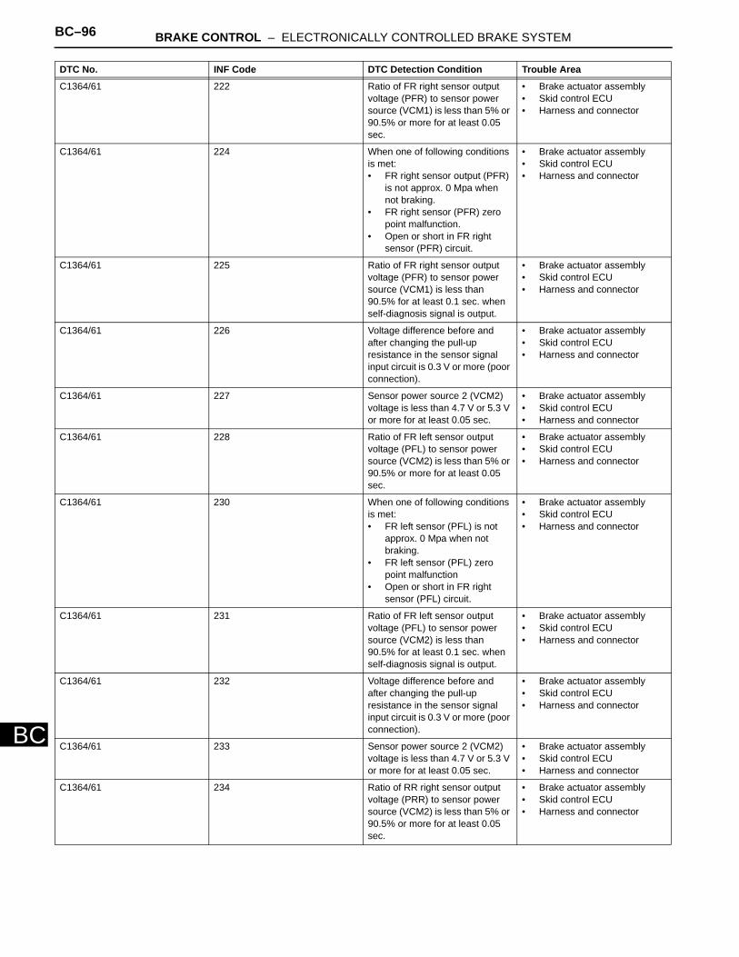
BC–96 BRAKE CONTROL – ELECTRONICALLY CONTROLLED BRAKE SYSTEM
BC
C1364/61 222 Ratio of FR right sensor output voltage (PFR) to sensor power source (VCM1) is less than 5% or 90.5% or more for at least 0.05 sec.
• Brake actuator assembly • Skid control ECU • Harness and connector
C1364/61 224 When one of following conditions is met:• FR right sensor output (PFR)
is not approx. 0 Mpa when not braking.
• FR right sensor (PFR) zero point malfunction.
• Open or short in FR right sensor (PFR) circuit.
• Brake actuator assembly • Skid control ECU • Harness and connector
C1364/61 225 Ratio of FR right sensor output voltage (PFR) to sensor power source (VCM1) is less than 90.5% for at least 0.1 sec. when self-diagnosis signal is output.
• Brake actuator assembly • Skid control ECU • Harness and connector
C1364/61 226 Voltage difference before and after changing the pull-up resistance in the sensor signal input circuit is 0.3 V or more (poor connection).
• Brake actuator assembly • Skid control ECU • Harness and connector
C1364/61 227 Sensor power source 2 (VCM2) voltage is less than 4.7 V or 5.3 V or more for at least 0.05 sec.
• Brake actuator assembly • Skid control ECU • Harness and connector
C1364/61 228 Ratio of FR left sensor output voltage (PFL) to sensor power source (VCM2) is less than 5% or 90.5% or more for at least 0.05 sec.
• Brake actuator assembly • Skid control ECU • Harness and connector
C1364/61 230 When one of following conditions is met:• FR left sensor (PFL) is not
approx. 0 Mpa when not braking.
• FR left sensor (PFL) zero point malfunction
• Open or short in FR right sensor (PFL) circuit.
• Brake actuator assembly • Skid control ECU • Harness and connector
C1364/61 231 Ratio of FR left sensor output voltage (PFL) to sensor power source (VCM2) is less than 90.5% for at least 0.1 sec. when self-diagnosis signal is output.
• Brake actuator assembly • Skid control ECU • Harness and connector
C1364/61 232 Voltage difference before and after changing the pull-up resistance in the sensor signal input circuit is 0.3 V or more (poor connection).
• Brake actuator assembly • Skid control ECU • Harness and connector
C1364/61 233 Sensor power source 2 (VCM2) voltage is less than 4.7 V or 5.3 V or more for at least 0.05 sec.
• Brake actuator assembly • Skid control ECU • Harness and connector
C1364/61 234 Ratio of RR right sensor output voltage (PRR) to sensor power source (VCM2) is less than 5% or 90.5% or more for at least 0.05 sec.
• Brake actuator assembly • Skid control ECU • Harness and connector
DTC No. INF Code DTC Detection Condition Trouble Area
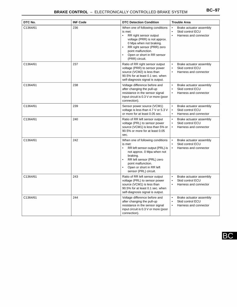
BRAKE CONTROL – ELECTRONICALLY CONTROLLED BRAKE SYSTEM BC–97
BC
C1364/61 236 When one of following conditions is met:• RR right sensor output
voltage (PRR) is not approx. 0 Mpa when not braking.
• RR right sensor (PRR) zero point malfunction.
• Open or short in RR sensor (PRR) circuit.
• Brake actuator assembly • Skid control ECU • Harness and connector
C1364/61 237 Ratio of RR right sensor output voltage (PRR) to sensor power source (VCM2) is less than 90.5% for at least 0.1 sec. when self-diagnosis signal is output.
• Brake actuator assembly • Skid control ECU • Harness and connector
C1364/61 238 Voltage difference before and after changing the pull-up resistance in the sensor signal input circuit is 0.3 V or more (poor connection).
• Brake actuator assembly • Skid control ECU • Harness and connector
C1364/61 239 Sensor power source (VCM1) voltage is less than 4.7 V or 5.3 V or more for at least 0.05 sec.
• Brake actuator assembly • Skid control ECU • Harness and connector
C1364/61 240 Ratio of RR left sensor output voltage (PRL) to sensor power source (VCM1) is less than 5% or 90.5% or more for at least 0.05 sec.
• Brake actuator assembly • Skid control ECU • Harness and connector
C1364/61 242 When one of following conditions is met:• RR left sensor output (PRL) is
not approx. 0 Mpa when not braking.
• RR left sensor (PRL) zero point malfunction.
• Open or short in RR left sensor (PRL) circuit.
• Brake actuator assembly • Skid control ECU • Harness and connector
C1364/61 243 Ratio of RR left sensor output voltage (PRL) to sensor power source (VCM1) is less than 90.5% for at least 0.1 sec. when self-diagnosis signal is output.
• Brake actuator assembly • Skid control ECU • Harness and connector
C1364/61 244 Voltage difference before and after changing the pull-up resistance in the sensor signal input circuit is 0.3 V or more (poor connection).
• Brake actuator assembly • Skid control ECU • Harness and connector
DTC No. INF Code DTC Detection Condition Trouble Area
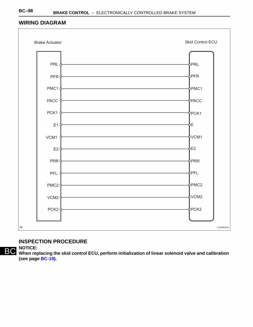
BC–98 BRAKE CONTROL – ELECTRONICALLY CONTROLLED BRAKE SYSTEM
BC
WIRING DIAGRAM
INSPECTION PROCEDURENOTICE:When replacing the skid control ECU, perform initialization of linear solenoid valve and calibration (see page BC-19).
Brake Actuator Skid Control ECU
PRL PRL
PFR PFR
PMC1 PMC1
PCK1 PCK1
E1 E
VCM1 VCM1
E2 E2
PRR PRR
PFL PFL
PMC2 PMC2
VCM2 VCM2
PCK2 PCK2
PACC PACC
C126252E01
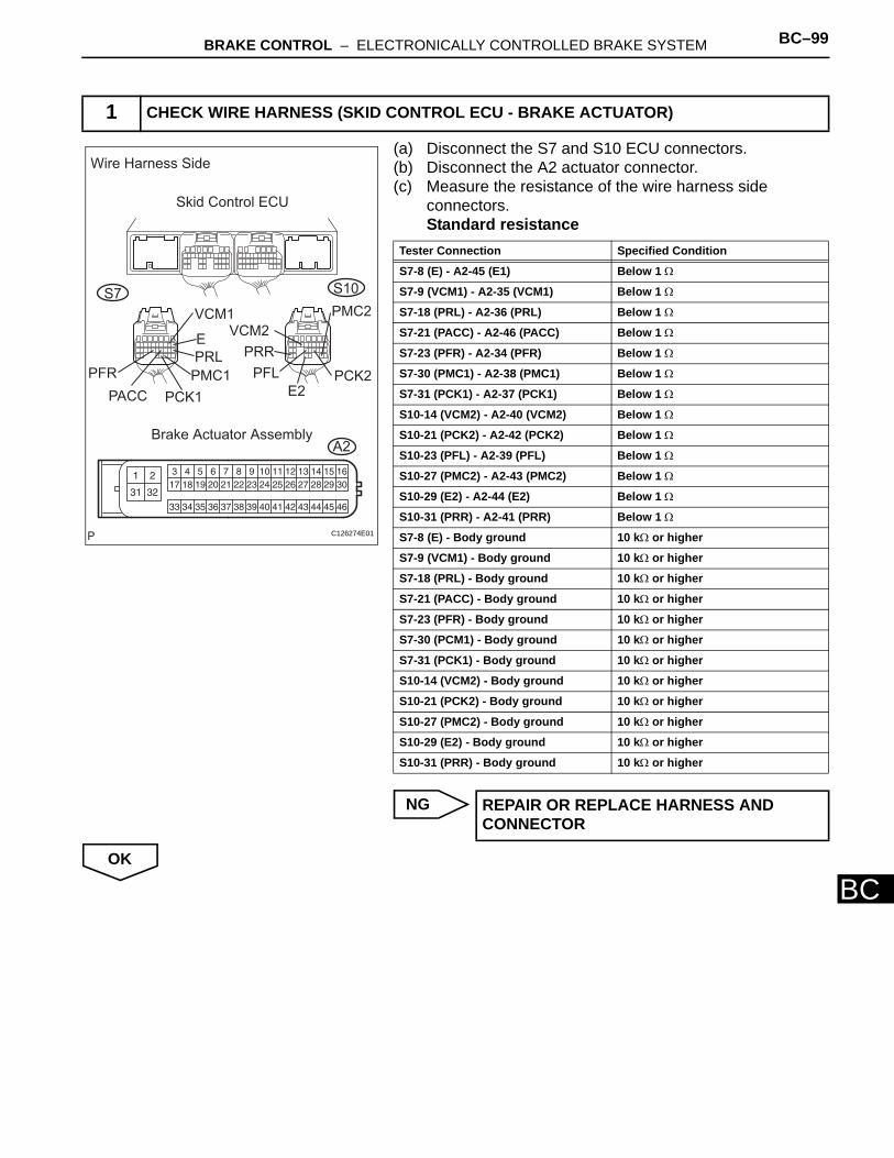
BRAKE CONTROL – ELECTRONICALLY CONTROLLED BRAKE SYSTEM BC–99
BC
(a) Disconnect the S7 and S10 ECU connectors.(b) Disconnect the A2 actuator connector.(c) Measure the resistance of the wire harness side
connectors.Standard resistance
NG
OK
1 CHECK WIRE HARNESS (SKID CONTROL ECU - BRAKE ACTUATOR)
Wire Harness Side
Skid Control ECU
S7 S10
VCM1VCM2
PFR
PACC PCK1
PMC1
PRL
E
PMC2
PCK2E2
PFL
PRR
Brake Actuator AssemblyA2
C126274E01
Tester Connection Specified Condition
S7-8 (E) - A2-45 (E1) Below 1 Ω
S7-9 (VCM1) - A2-35 (VCM1) Below 1 Ω
S7-18 (PRL) - A2-36 (PRL) Below 1 Ω
S7-21 (PACC) - A2-46 (PACC) Below 1 Ω
S7-23 (PFR) - A2-34 (PFR) Below 1 Ω
S7-30 (PMC1) - A2-38 (PMC1) Below 1 Ω
S7-31 (PCK1) - A2-37 (PCK1) Below 1 Ω
S10-14 (VCM2) - A2-40 (VCM2) Below 1 Ω
S10-21 (PCK2) - A2-42 (PCK2) Below 1 Ω
S10-23 (PFL) - A2-39 (PFL) Below 1 Ω
S10-27 (PMC2) - A2-43 (PMC2) Below 1 Ω
S10-29 (E2) - A2-44 (E2) Below 1 Ω
S10-31 (PRR) - A2-41 (PRR) Below 1 Ω
S7-8 (E) - Body ground 10 kΩ or higher
S7-9 (VCM1) - Body ground 10 kΩ or higher
S7-18 (PRL) - Body ground 10 kΩ or higher
S7-21 (PACC) - Body ground 10 kΩ or higher
S7-23 (PFR) - Body ground 10 kΩ or higher
S7-30 (PCM1) - Body ground 10 kΩ or higher
S7-31 (PCK1) - Body ground 10 kΩ or higher
S10-14 (VCM2) - Body ground 10 kΩ or higher
S10-21 (PCK2) - Body ground 10 kΩ or higher
S10-27 (PMC2) - Body ground 10 kΩ or higher
S10-29 (E2) - Body ground 10 kΩ or higher
S10-31 (PRR) - Body ground 10 kΩ or higher
REPAIR OR REPLACE HARNESS AND CONNECTOR
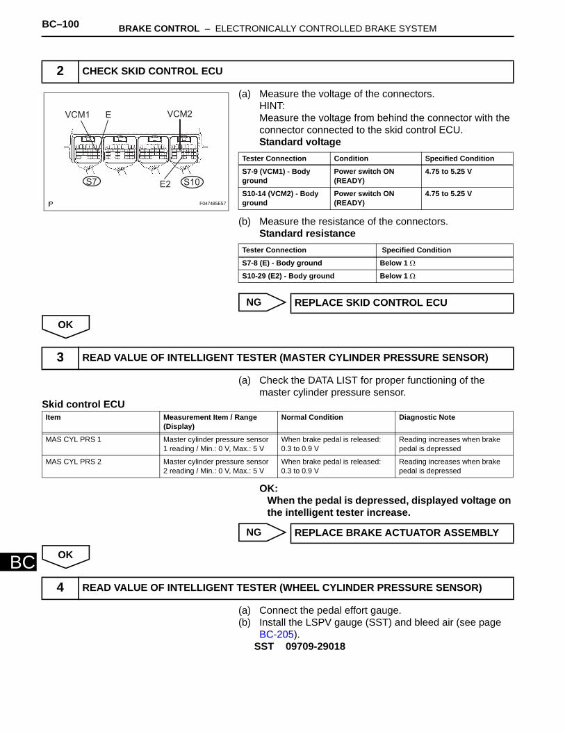
BC–100 BRAKE CONTROL – ELECTRONICALLY CONTROLLED BRAKE SYSTEM
BC
(a) Measure the voltage of the connectors.HINT:Measure the voltage from behind the connector with the connector connected to the skid control ECU.Standard voltage
(b) Measure the resistance of the connectors.Standard resistance
NG
OK
(a) Check the DATA LIST for proper functioning of the master cylinder pressure sensor.
Skid control ECU
OK:When the pedal is depressed, displayed voltage on the intelligent tester increase.
NG
OK
(a) Connect the pedal effort gauge. (b) Install the LSPV gauge (SST) and bleed air (see page
BC-205).SST 09709-29018
2 CHECK SKID CONTROL ECU
VCM1 E VCM2
E2S7 S10
F047485E57
Tester Connection Condition Specified Condition
S7-9 (VCM1) - Body ground
Power switch ON (READY)
4.75 to 5.25 V
S10-14 (VCM2) - Body ground
Power switch ON (READY)
4.75 to 5.25 V
Tester Connection Specified Condition
S7-8 (E) - Body ground Below 1 Ω
S10-29 (E2) - Body ground Below 1 Ω
REPLACE SKID CONTROL ECU
3 READ VALUE OF INTELLIGENT TESTER (MASTER CYLINDER PRESSURE SENSOR)
Item Measurement Item / Range (Display)
Normal Condition Diagnostic Note
MAS CYL PRS 1 Master cylinder pressure sensor 1 reading / Min.: 0 V, Max.: 5 V
When brake pedal is released: 0.3 to 0.9 V
Reading increases when brake pedal is depressed
MAS CYL PRS 2 Master cylinder pressure sensor 2 reading / Min.: 0 V, Max.: 5 V
When brake pedal is released: 0.3 to 0.9 V
Reading increases when brake pedal is depressed
REPLACE BRAKE ACTUATOR ASSEMBLY
4 READ VALUE OF INTELLIGENT TESTER (WHEEL CYLINDER PRESSURE SENSOR)
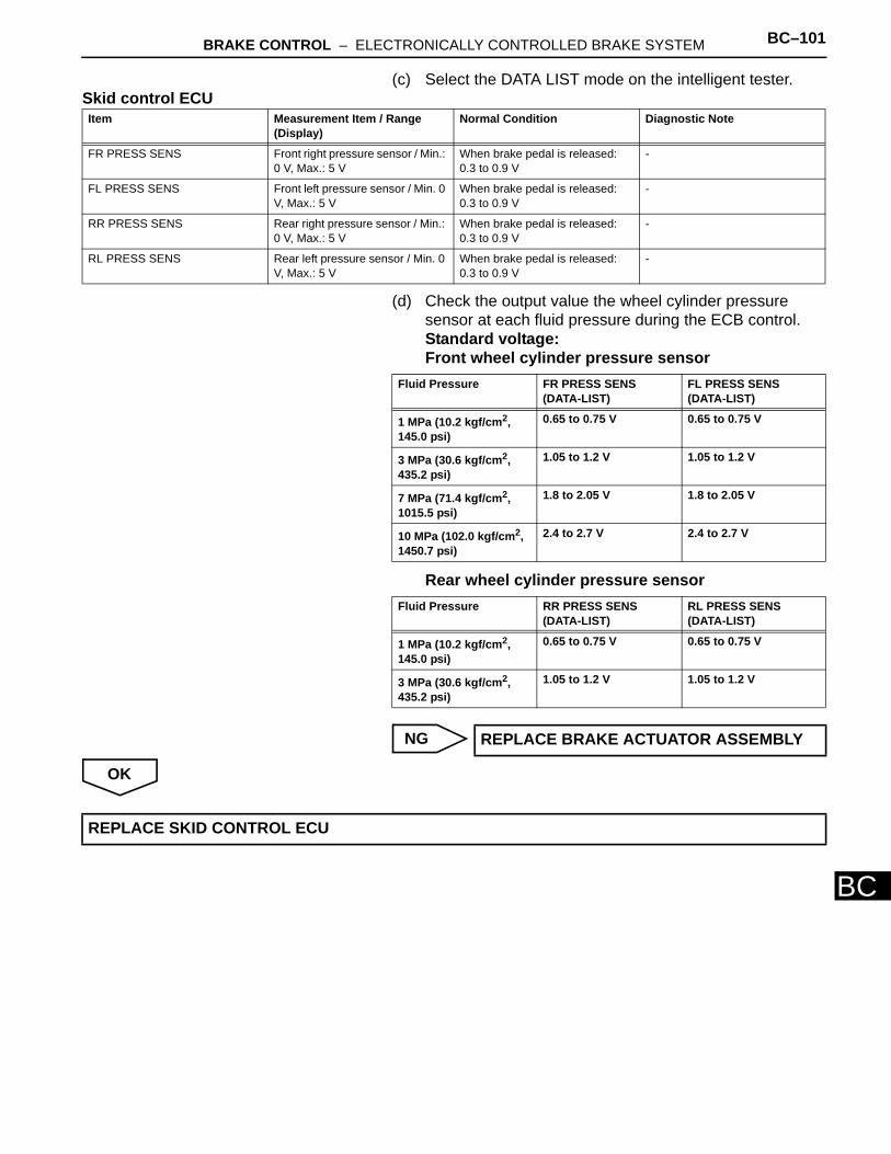
BRAKE CONTROL – ELECTRONICALLY CONTROLLED BRAKE SYSTEM BC–101
BC
(c) Select the DATA LIST mode on the intelligent tester.Skid control ECU
(d) Check the output value the wheel cylinder pressure sensor at each fluid pressure during the ECB control.Standard voltage:Front wheel cylinder pressure sensor
Rear wheel cylinder pressure sensor
NG
OK
Item Measurement Item / Range (Display)
Normal Condition Diagnostic Note
FR PRESS SENS Front right pressure sensor / Min.: 0 V, Max.: 5 V
When brake pedal is released: 0.3 to 0.9 V
-
FL PRESS SENS Front left pressure sensor / Min. 0 V, Max.: 5 V
When brake pedal is released: 0.3 to 0.9 V
-
RR PRESS SENS Rear right pressure sensor / Min.: 0 V, Max.: 5 V
When brake pedal is released: 0.3 to 0.9 V
-
RL PRESS SENS Rear left pressure sensor / Min. 0 V, Max.: 5 V
When brake pedal is released: 0.3 to 0.9 V
-
Fluid Pressure FR PRESS SENS (DATA-LIST)
FL PRESS SENS (DATA-LIST)
1 MPa (10.2 kgf/cm2, 145.0 psi)
0.65 to 0.75 V 0.65 to 0.75 V
3 MPa (30.6 kgf/cm2, 435.2 psi)
1.05 to 1.2 V 1.05 to 1.2 V
7 MPa (71.4 kgf/cm2, 1015.5 psi)
1.8 to 2.05 V 1.8 to 2.05 V
10 MPa (102.0 kgf/cm2, 1450.7 psi)
2.4 to 2.7 V 2.4 to 2.7 V
Fluid Pressure RR PRESS SENS (DATA-LIST)
RL PRESS SENS (DATA-LIST)
1 MPa (10.2 kgf/cm2, 145.0 psi)
0.65 to 0.75 V 0.65 to 0.75 V
3 MPa (30.6 kgf/cm2, 435.2 psi)
1.05 to 1.2 V 1.05 to 1.2 V
REPLACE BRAKE ACTUATOR ASSEMBLY
REPLACE SKID CONTROL ECU
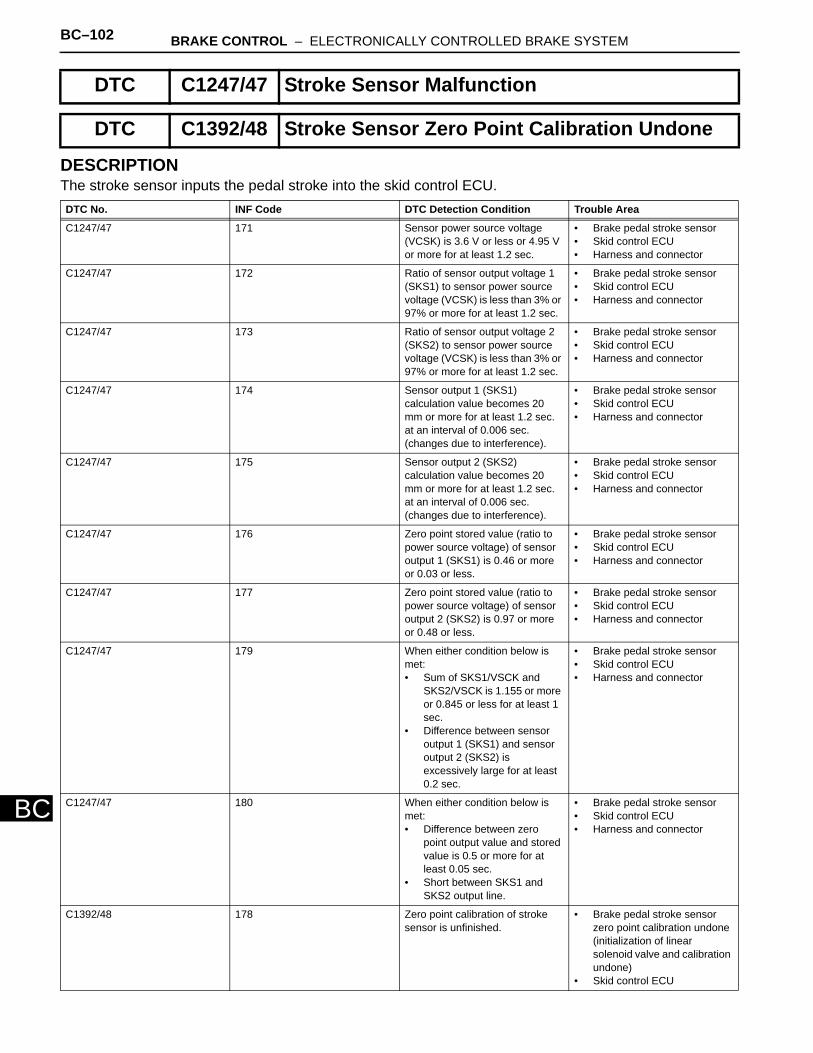
BC–102 BRAKE CONTROL – ELECTRONICALLY CONTROLLED BRAKE SYSTEM
BC
DESCRIPTIONThe stroke sensor inputs the pedal stroke into the skid control ECU.
DTC C1247/47 Stroke Sensor Malfunction
DTC C1392/48 Stroke Sensor Zero Point Calibration Undone
DTC No. INF Code DTC Detection Condition Trouble Area
C1247/47 171 Sensor power source voltage (VCSK) is 3.6 V or less or 4.95 V or more for at least 1.2 sec.
• Brake pedal stroke sensor • Skid control ECU • Harness and connector
C1247/47 172 Ratio of sensor output voltage 1 (SKS1) to sensor power source voltage (VCSK) is less than 3% or 97% or more for at least 1.2 sec.
• Brake pedal stroke sensor • Skid control ECU • Harness and connector
C1247/47 173 Ratio of sensor output voltage 2 (SKS2) to sensor power source voltage (VCSK) is less than 3% or 97% or more for at least 1.2 sec.
• Brake pedal stroke sensor • Skid control ECU • Harness and connector
C1247/47 174 Sensor output 1 (SKS1) calculation value becomes 20 mm or more for at least 1.2 sec. at an interval of 0.006 sec. (changes due to interference).
• Brake pedal stroke sensor • Skid control ECU • Harness and connector
C1247/47 175 Sensor output 2 (SKS2) calculation value becomes 20 mm or more for at least 1.2 sec. at an interval of 0.006 sec. (changes due to interference).
• Brake pedal stroke sensor • Skid control ECU • Harness and connector
C1247/47 176 Zero point stored value (ratio to power source voltage) of sensor output 1 (SKS1) is 0.46 or more or 0.03 or less.
• Brake pedal stroke sensor • Skid control ECU • Harness and connector
C1247/47 177 Zero point stored value (ratio to power source voltage) of sensor output 2 (SKS2) is 0.97 or more or 0.48 or less.
• Brake pedal stroke sensor • Skid control ECU • Harness and connector
C1247/47 179 When either condition below is met:• Sum of SKS1/VSCK and
SKS2/VSCK is 1.155 or more or 0.845 or less for at least 1 sec.
• Difference between sensor output 1 (SKS1) and sensor output 2 (SKS2) is excessively large for at least 0.2 sec.
• Brake pedal stroke sensor • Skid control ECU • Harness and connector
C1247/47 180 When either condition below is met:• Difference between zero
point output value and stored value is 0.5 or more for at least 0.05 sec.
• Short between SKS1 and SKS2 output line.
• Brake pedal stroke sensor • Skid control ECU • Harness and connector
C1392/48 178 Zero point calibration of stroke sensor is unfinished.
• Brake pedal stroke sensor zero point calibration undone (initialization of linear solenoid valve and calibration undone)
• Skid control ECU
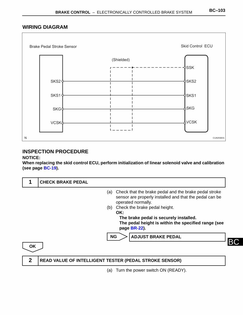
BRAKE CONTROL – ELECTRONICALLY CONTROLLED BRAKE SYSTEM BC–103
BC
WIRING DIAGRAM
INSPECTION PROCEDURENOTICE:When replacing the skid control ECU, perform initialization of linear solenoid valve and calibration (see page BC-19).
(a) Check that the brake pedal and the brake pedal stroke sensor are properly installed and that the pedal can be operated normally.
(b) Check the brake pedal height.OK:
The brake pedal is securely installed. The pedal height is within the specified range (see page BR-22).
NG
OK
(a) Turn the power switch ON (READY).
1 CHECK BRAKE PEDAL
Brake Pedal Stroke Sensor Skid Control ECU
(Shielded)
SKS2
SKS1
SKG
VCSK
SSK
SKS2
SKS1
SKG
VCSK
C126253E01
ADJUST BRAKE PEDAL
2 READ VALUE OF INTELLIGENT TESTER (PEDAL STROKE SENSOR)
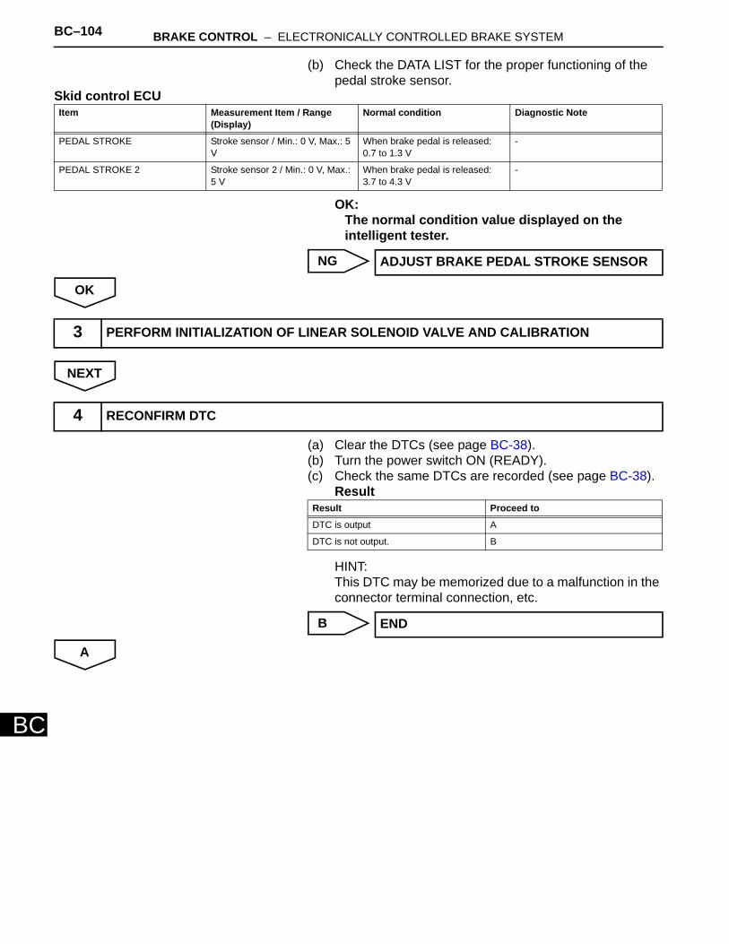
BC–104 BRAKE CONTROL – ELECTRONICALLY CONTROLLED BRAKE SYSTEM
BC
(b) Check the DATA LIST for the proper functioning of the pedal stroke sensor.
Skid control ECU
OK:The normal condition value displayed on the intelligent tester.
NG
OK
NEXT
(a) Clear the DTCs (see page BC-38). (b) Turn the power switch ON (READY). (c) Check the same DTCs are recorded (see page BC-38).
Result
HINT:This DTC may be memorized due to a malfunction in the connector terminal connection, etc.
B
A
Item Measurement Item / Range (Display)
Normal condition Diagnostic Note
PEDAL STROKE Stroke sensor / Min.: 0 V, Max.: 5 V
When brake pedal is released: 0.7 to 1.3 V
-
PEDAL STROKE 2 Stroke sensor 2 / Min.: 0 V, Max.: 5 V
When brake pedal is released: 3.7 to 4.3 V
-
ADJUST BRAKE PEDAL STROKE SENSOR
3 PERFORM INITIALIZATION OF LINEAR SOLENOID VALVE AND CALIBRATION
4 RECONFIRM DTC
Result Proceed to
DTC is output A
DTC is not output. B
END
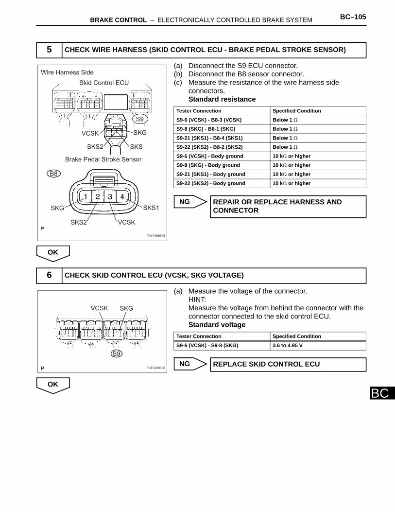
BRAKE CONTROL – ELECTRONICALLY CONTROLLED BRAKE SYSTEM BC–105
BC
(a) Disconnect the S9 ECU connector.(b) Disconnect the B8 sensor connector.(c) Measure the resistance of the wire harness side
connectors.Standard resistance
NG
OK
(a) Measure the voltage of the connector.HINT:Measure the voltage from behind the connector with the connector connected to the skid control ECU.Standard voltage
NG
OK
5 CHECK WIRE HARNESS (SKID CONTROL ECU - BRAKE PEDAL STROKE SENSOR)
Skid Control ECU
Brake Pedal Stroke Sensor
S9
VCSK
SKSSKS2
SKG
VCSK
SKS1
SKS2
SKG
Wire Harness Side
B8
F047488E05
Tester Connection Specified Condition
S9-6 (VCSK) - B8-3 (VCSK) Below 1 Ω
S9-8 (SKG) - B8-1 (SKG) Below 1 Ω
S9-21 (SKS1) - B8-4 (SKS1) Below 1 Ω
S9-22 (SKS2) - B8-2 (SKS2) Below 1 Ω
S9-6 (VCSK) - Body ground 10 kΩ or higher
S9-8 (SKG) - Body ground 10 kΩ or higher
S9-21 (SKS1) - Body ground 10 kΩ or higher
S9-22 (SKS2) - Body ground 10 kΩ or higher
REPAIR OR REPLACE HARNESS AND CONNECTOR
6 CHECK SKID CONTROL ECU (VCSK, SKG VOLTAGE)
VCSK SKG
S9
F047485E58
Tester Connection Specified Condition
S9-6 (VCSK) - S9-8 (SKG) 3.6 to 4.95 V
REPLACE SKID CONTROL ECU
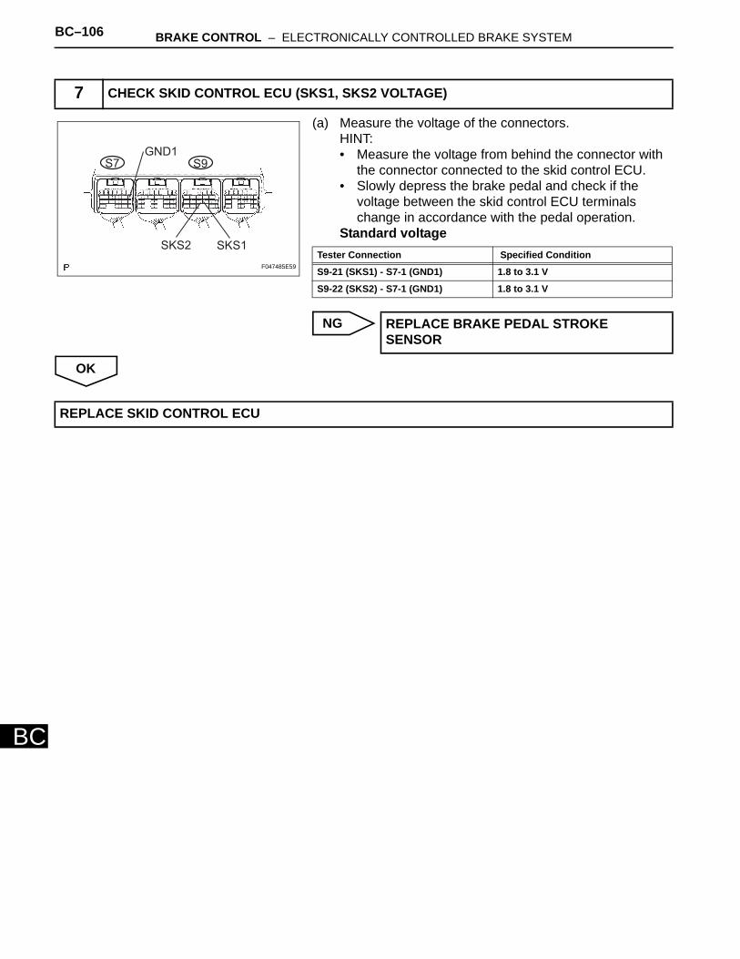
BC–106 BRAKE CONTROL – ELECTRONICALLY CONTROLLED BRAKE SYSTEM
BC
(a) Measure the voltage of the connectors.HINT:• Measure the voltage from behind the connector with
the connector connected to the skid control ECU. • Slowly depress the brake pedal and check if the
voltage between the skid control ECU terminals change in accordance with the pedal operation.
Standard voltage
NG
OK
7 CHECK SKID CONTROL ECU (SKS1, SKS2 VOLTAGE)
S7 S9GND1
SKS2 SKS1
F047485E59
Tester Connection Specified Condition
S9-21 (SKS1) - S7-1 (GND1) 1.8 to 3.1 V
S9-22 (SKS2) - S7-1 (GND1) 1.8 to 3.1 V
REPLACE BRAKE PEDAL STROKE SENSOR
REPLACE SKID CONTROL ECU
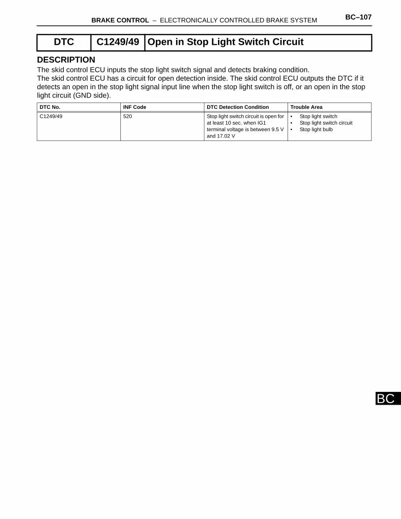
BRAKE CONTROL – ELECTRONICALLY CONTROLLED BRAKE SYSTEM BC–107
BC
DESCRIPTIONThe skid control ECU inputs the stop light switch signal and detects braking condition. The skid control ECU has a circuit for open detection inside. The skid control ECU outputs the DTC if it detects an open in the stop light signal input line when the stop light switch is off, or an open in the stop light circuit (GND side).
DTC C1249/49 Open in Stop Light Switch Circuit
DTC No. INF Code DTC Detection Condition Trouble Area
C1249/49 520 Stop light switch circuit is open for at least 10 sec. when IG1 terminal voltage is between 9.5 V and 17.02 V
• Stop light switch • Stop light switch circuit • Stop light bulb
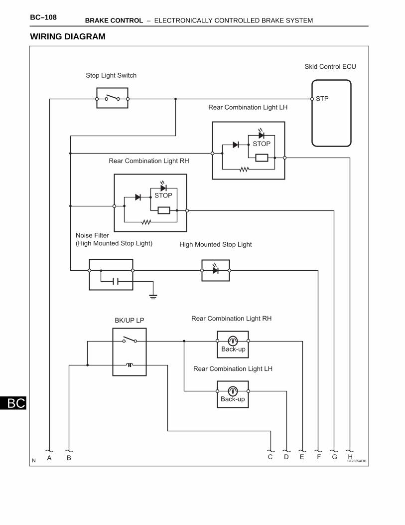
BC–108 BRAKE CONTROL – ELECTRONICALLY CONTROLLED BRAKE SYSTEM
BC
WIRING DIAGRAM
Stop Light Switch
Skid Control ECU
Rear Combination Light LH
STP
STOP
Rear Combination Light RH
STOP
Noise Filter
(High Mounted Stop Light) High Mounted Stop Light
Rear Combination Light RH
Back-up
Rear Combination Light LH
BK/UP LP
A B C D E F G H
Back-up
C126254E01
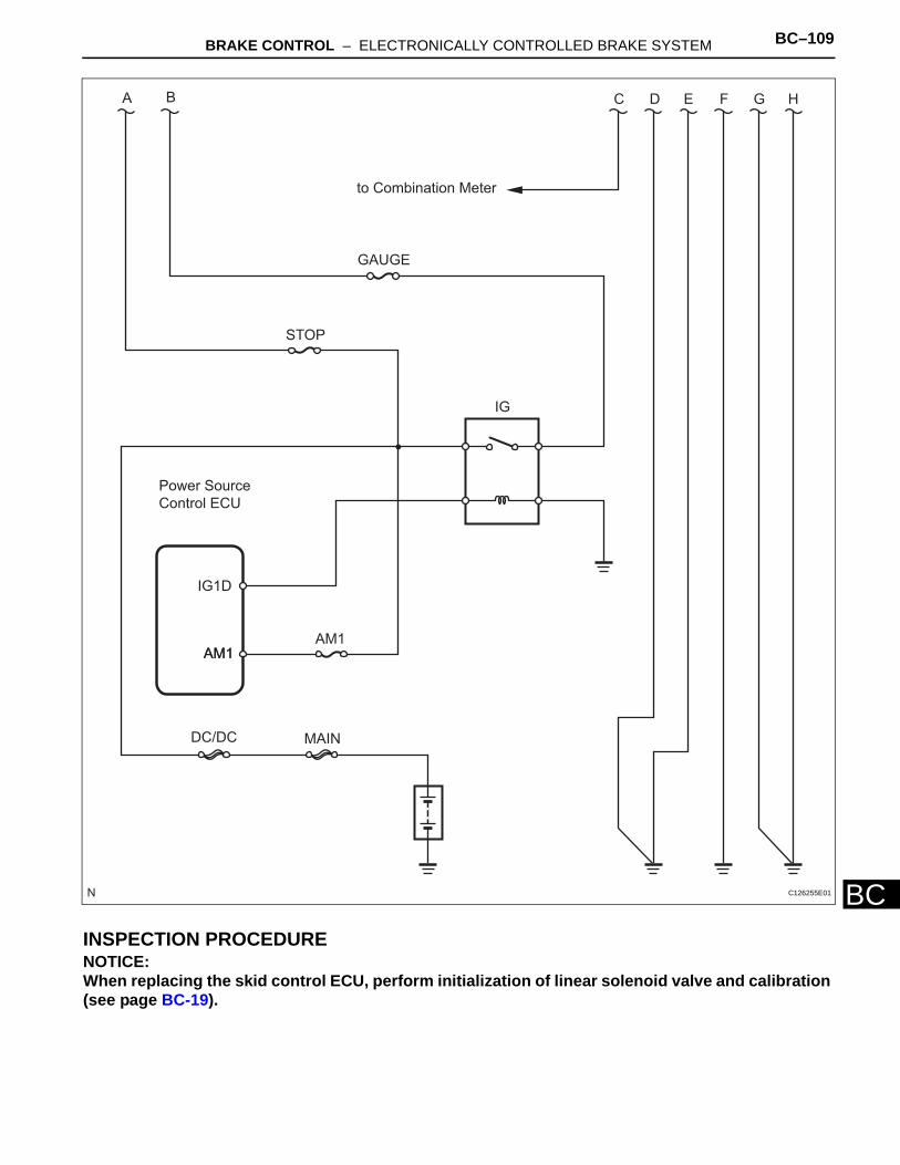
BRAKE CONTROL – ELECTRONICALLY CONTROLLED BRAKE SYSTEM BC–109
BCINSPECTION PROCEDURENOTICE:When replacing the skid control ECU, perform initialization of linear solenoid valve and calibration (see page BC-19).
A B C D E F G H
to Combination Meter
GAUGE
STOP
IG
Power Source
Control ECU
IG1D
AM1AM1AM1
DC/DC MAIN
C126255E01
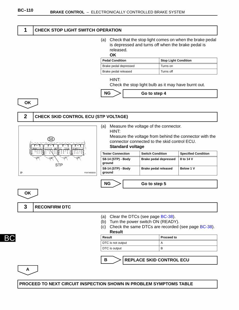
BC–110 BRAKE CONTROL – ELECTRONICALLY CONTROLLED BRAKE SYSTEM
BC
(a) Check that the stop light comes on when the brake pedal is depressed and turns off when the brake pedal is released.OK
HINT:Check the stop light bulb as it may have burnt out.
NG
OK
(a) Measure the voltage of the connector.HINT:Measure the voltage from behind the connector with the connector connected to the skid control ECU.Standard voltage
NG
OK
(a) Clear the DTCs (see page BC-38). (b) Turn the power switch ON (READY). (c) Check the same DTCs are recorded (see page BC-38).
Result
B
A
1 CHECK STOP LIGHT SWITCH OPERATION
Pedal Condition Stop Light Condition
Brake pedal depressed Turns on
Brake pedal released Turns off
Go to step 4
2 CHECK SKID CONTROL ECU (STP VOLTAGE)
S8
STP
F047485E60
Tester Connection Switch Condition Specified Condition
S8-14 (STP) - Body ground
Brake pedal depressed 8 to 14 V
S8-14 (STP) - Body ground
Brake pedal released Below 1 V
Go to step 5
3 RECONFIRM DTC
Result Proceed to
DTC is not output A
DTC is output B
REPLACE SKID CONTROL ECU
PROCEED TO NEXT CIRCUIT INSPECTION SHOWN IN PROBLEM SYMPTOMS TABLE
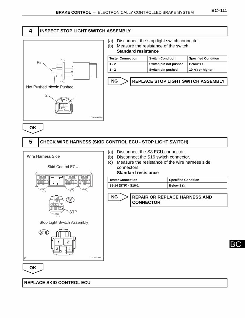
BRAKE CONTROL – ELECTRONICALLY CONTROLLED BRAKE SYSTEM BC–111
BC
(a) Disconnect the stop light switch connector. (b) Measure the resistance of the switch.
Standard resistance
NG
OK
(a) Disconnect the S8 ECU connector.(b) Disconnect the S16 switch connector.(c) Measure the resistance of the wire harness side
connectors.Standard resistance
NG
OK
4 INSPECT STOP LIGHT SWITCH ASSEMBLY
Pin
Not Pushed Pushed
2 1
C108891E04
Tester Connection Switch Condition Specified Condition
1 - 2 Switch pin not pushed Below 1 Ω
1 - 2 Switch pin pushed 10 kΩ or higher
REPLACE STOP LIGHT SWITCH ASSEMBLY
5 CHECK WIRE HARNESS (SKID CONTROL ECU - STOP LIGHT SWITCH)
Wire Harness Side
Skid Control ECU
STP
Stop Light Switch Assembly
S16
S8
C126276E01
Tester Connection Specified Condition
S8-14 (STP) - S16-1 Below 1 Ω
REPAIR OR REPLACE HARNESS AND CONNECTOR
REPLACE SKID CONTROL ECU
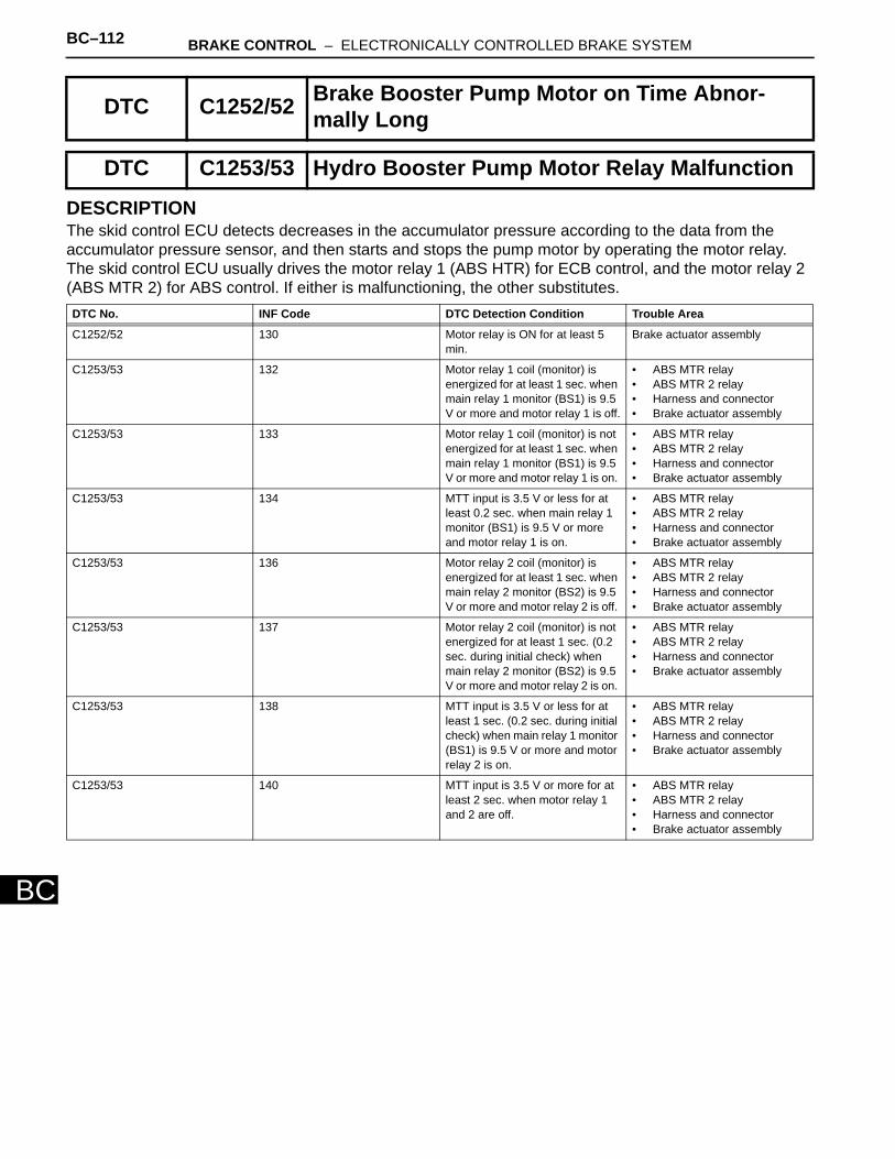
BC–112 BRAKE CONTROL – ELECTRONICALLY CONTROLLED BRAKE SYSTEM
BC
DESCRIPTIONThe skid control ECU detects decreases in the accumulator pressure according to the data from the accumulator pressure sensor, and then starts and stops the pump motor by operating the motor relay. The skid control ECU usually drives the motor relay 1 (ABS HTR) for ECB control, and the motor relay 2 (ABS MTR 2) for ABS control. If either is malfunctioning, the other substitutes.
DTC C1252/52 Brake Booster Pump Motor on Time Abnor-mally Long
DTC C1253/53 Hydro Booster Pump Motor Relay Malfunction
DTC No. INF Code DTC Detection Condition Trouble Area
C1252/52 130 Motor relay is ON for at least 5 min.
Brake actuator assembly
C1253/53 132 Motor relay 1 coil (monitor) is energized for at least 1 sec. when main relay 1 monitor (BS1) is 9.5 V or more and motor relay 1 is off.
• ABS MTR relay • ABS MTR 2 relay • Harness and connector • Brake actuator assembly
C1253/53 133 Motor relay 1 coil (monitor) is not energized for at least 1 sec. when main relay 1 monitor (BS1) is 9.5 V or more and motor relay 1 is on.
• ABS MTR relay • ABS MTR 2 relay • Harness and connector • Brake actuator assembly
C1253/53 134 MTT input is 3.5 V or less for at least 0.2 sec. when main relay 1 monitor (BS1) is 9.5 V or more and motor relay 1 is on.
• ABS MTR relay • ABS MTR 2 relay • Harness and connector • Brake actuator assembly
C1253/53 136 Motor relay 2 coil (monitor) is energized for at least 1 sec. when main relay 2 monitor (BS2) is 9.5 V or more and motor relay 2 is off.
• ABS MTR relay • ABS MTR 2 relay • Harness and connector • Brake actuator assembly
C1253/53 137 Motor relay 2 coil (monitor) is not energized for at least 1 sec. (0.2 sec. during initial check) when main relay 2 monitor (BS2) is 9.5 V or more and motor relay 2 is on.
• ABS MTR relay • ABS MTR 2 relay • Harness and connector • Brake actuator assembly
C1253/53 138 MTT input is 3.5 V or less for at least 1 sec. (0.2 sec. during initial check) when main relay 1 monitor (BS1) is 9.5 V or more and motor relay 2 is on.
• ABS MTR relay • ABS MTR 2 relay • Harness and connector • Brake actuator assembly
C1253/53 140 MTT input is 3.5 V or more for at least 2 sec. when motor relay 1 and 2 are off.
• ABS MTR relay • ABS MTR 2 relay • Harness and connector • Brake actuator assembly
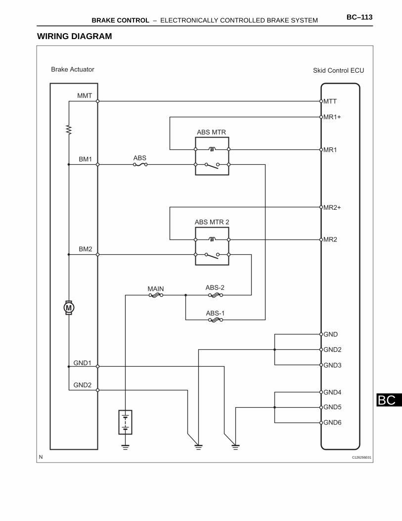
BRAKE CONTROL – ELECTRONICALLY CONTROLLED BRAKE SYSTEM BC–113
BC
WIRING DIAGRAM
Brake Actuator Skid Control ECU
MMT
BM1
BM2
GND2
MTT
MR1+
MR1
MR2+
MR2
GND
GND2
GND3
GND4
GND5
GND6
ABS MTR
ABS MTR 2
ABS-2
ABS-1
MAIN
GND1
ABS
C126256E01
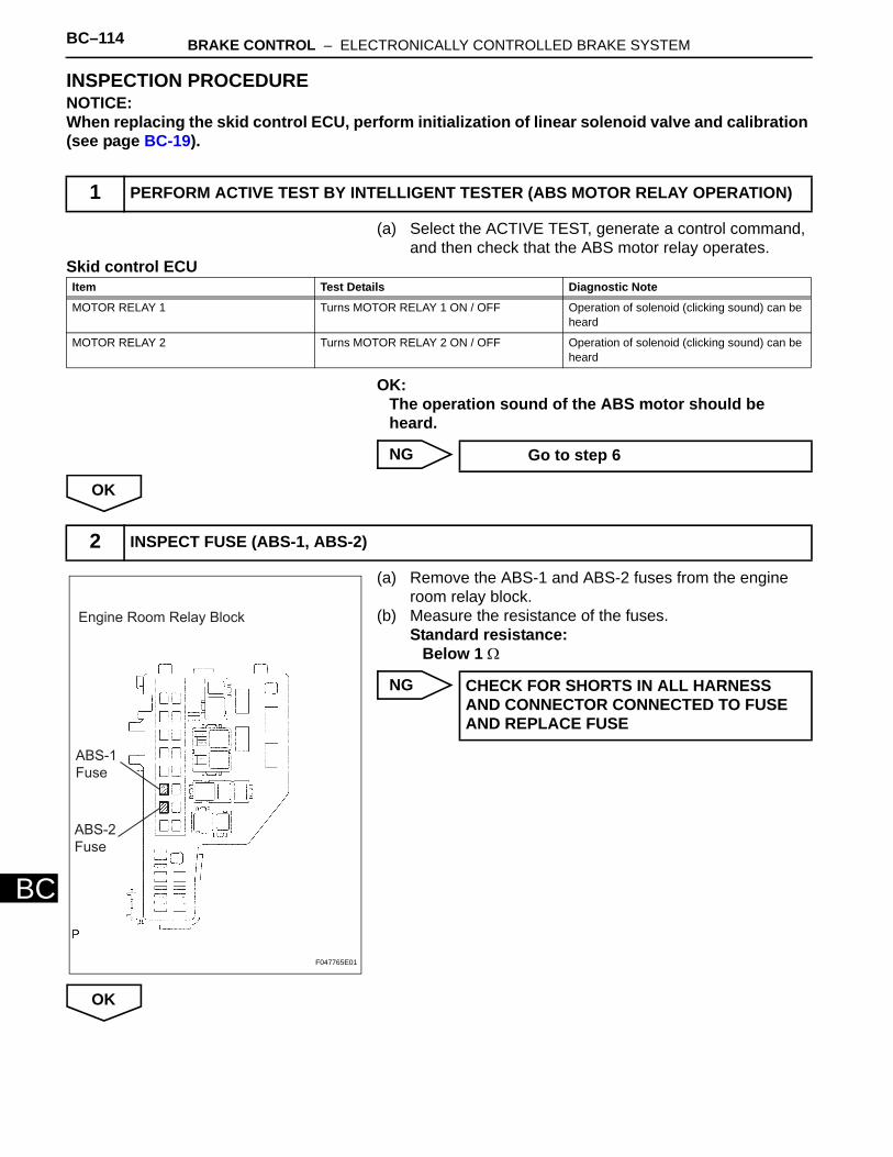
BC–114 BRAKE CONTROL – ELECTRONICALLY CONTROLLED BRAKE SYSTEM
BC
INSPECTION PROCEDURENOTICE:When replacing the skid control ECU, perform initialization of linear solenoid valve and calibration (see page BC-19).
(a) Select the ACTIVE TEST, generate a control command, and then check that the ABS motor relay operates.
Skid control ECU
OK:The operation sound of the ABS motor should be heard.
NG
OK
(a) Remove the ABS-1 and ABS-2 fuses from the engine room relay block.
(b) Measure the resistance of the fuses.Standard resistance:
Below 1 Ω
NG
OK
1 PERFORM ACTIVE TEST BY INTELLIGENT TESTER (ABS MOTOR RELAY OPERATION)
Item Test Details Diagnostic Note
MOTOR RELAY 1 Turns MOTOR RELAY 1 ON / OFF Operation of solenoid (clicking sound) can be heard
MOTOR RELAY 2 Turns MOTOR RELAY 2 ON / OFF Operation of solenoid (clicking sound) can be heard
Go to step 6
2 INSPECT FUSE (ABS-1, ABS-2)
Engine Room Relay Block
ABS-1
Fuse
ABS-2
Fuse
F047765E01
CHECK FOR SHORTS IN ALL HARNESS AND CONNECTOR CONNECTED TO FUSE AND REPLACE FUSE
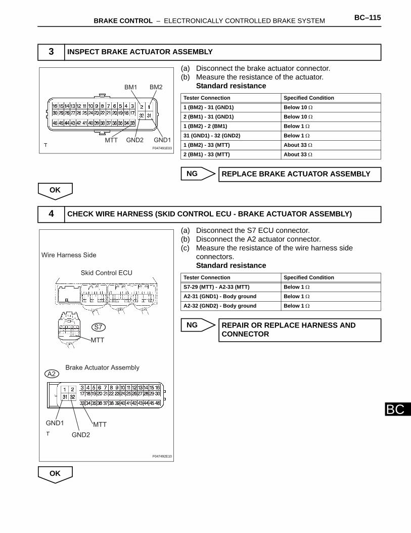
BRAKE CONTROL – ELECTRONICALLY CONTROLLED BRAKE SYSTEM BC–115
BC
(a) Disconnect the brake actuator connector. (b) Measure the resistance of the actuator.
Standard resistance
NG
OK
(a) Disconnect the S7 ECU connector. (b) Disconnect the A2 actuator connector.(c) Measure the resistance of the wire harness side
connectors.Standard resistance
NG
OK
3 INSPECT BRAKE ACTUATOR ASSEMBLY
BM1 BM2
GND1GND2MTTF047491E03
Tester Connection Specified Condition
1 (BM2) - 31 (GND1) Below 10 Ω
2 (BM1) - 31 (GND1) Below 10 Ω
1 (BM2) - 2 (BM1) Below 1 Ω
31 (GND1) - 32 (GND2) Below 1 Ω
1 (BM2) - 33 (MTT) About 33 Ω
2 (BM1) - 33 (MTT) About 33 Ω
REPLACE BRAKE ACTUATOR ASSEMBLY
4 CHECK WIRE HARNESS (SKID CONTROL ECU - BRAKE ACTUATOR ASSEMBLY)
Wire Harness Side
Skid Control ECU
MTT
Brake Actuator AssemblyA2
GND1
GND2
MTT
S7
F047492E10
Tester Connection Specified Condition
S7-29 (MTT) - A2-33 (MTT) Below 1 Ω
A2-31 (GND1) - Body ground Below 1 Ω
A2-32 (GND2) - Body ground Below 1 Ω
REPAIR OR REPLACE HARNESS AND CONNECTOR
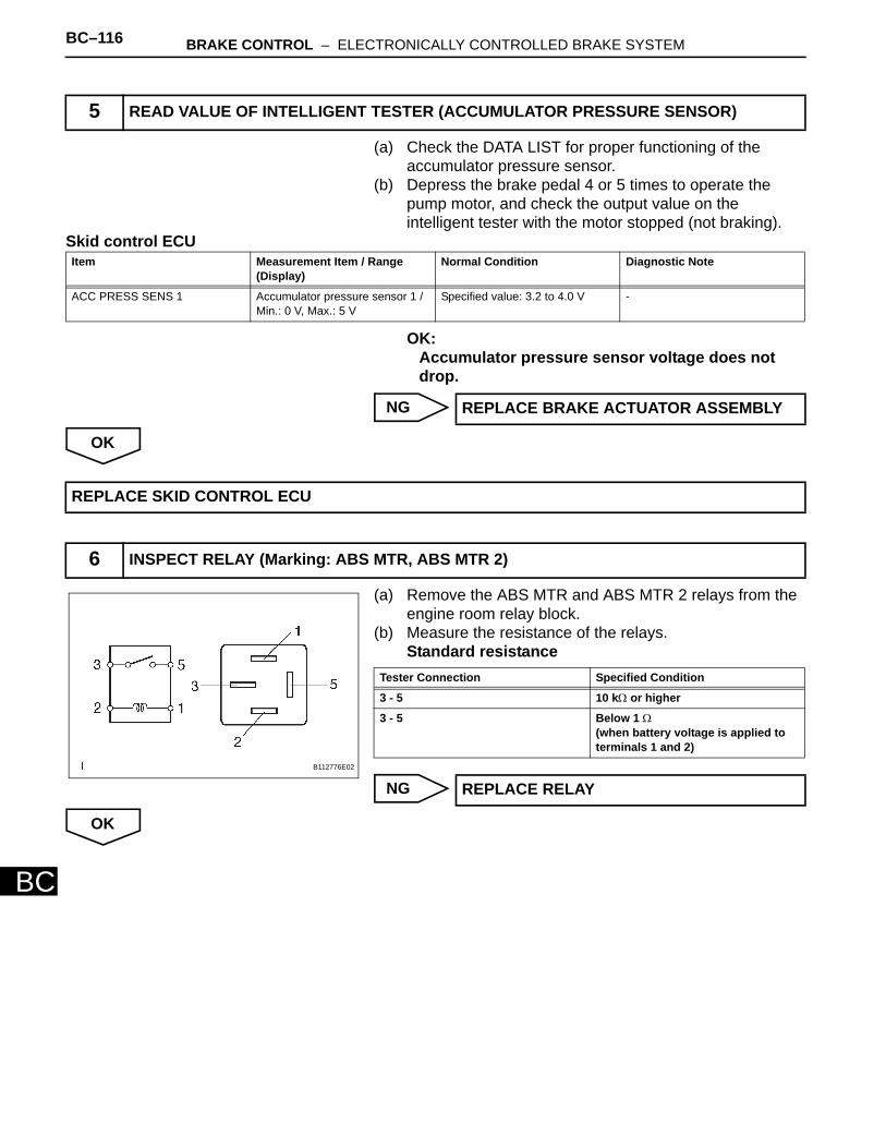
BC–116 BRAKE CONTROL – ELECTRONICALLY CONTROLLED BRAKE SYSTEM
BC
(a) Check the DATA LIST for proper functioning of the accumulator pressure sensor.
(b) Depress the brake pedal 4 or 5 times to operate the pump motor, and check the output value on the intelligent tester with the motor stopped (not braking).
Skid control ECU
OK:Accumulator pressure sensor voltage does not drop.
NG
OK
(a) Remove the ABS MTR and ABS MTR 2 relays from the engine room relay block.
(b) Measure the resistance of the relays.Standard resistance
NG
OK
5 READ VALUE OF INTELLIGENT TESTER (ACCUMULATOR PRESSURE SENSOR)
Item Measurement Item / Range (Display)
Normal Condition Diagnostic Note
ACC PRESS SENS 1 Accumulator pressure sensor 1 / Min.: 0 V, Max.: 5 V
Specified value: 3.2 to 4.0 V -
REPLACE BRAKE ACTUATOR ASSEMBLY
REPLACE SKID CONTROL ECU
6 INSPECT RELAY (Marking: ABS MTR, ABS MTR 2)
B112776E02
Tester Connection Specified Condition
3 - 5 10 kΩ or higher
3 - 5 Below 1 Ω (when battery voltage is applied to terminals 1 and 2)
REPLACE RELAY
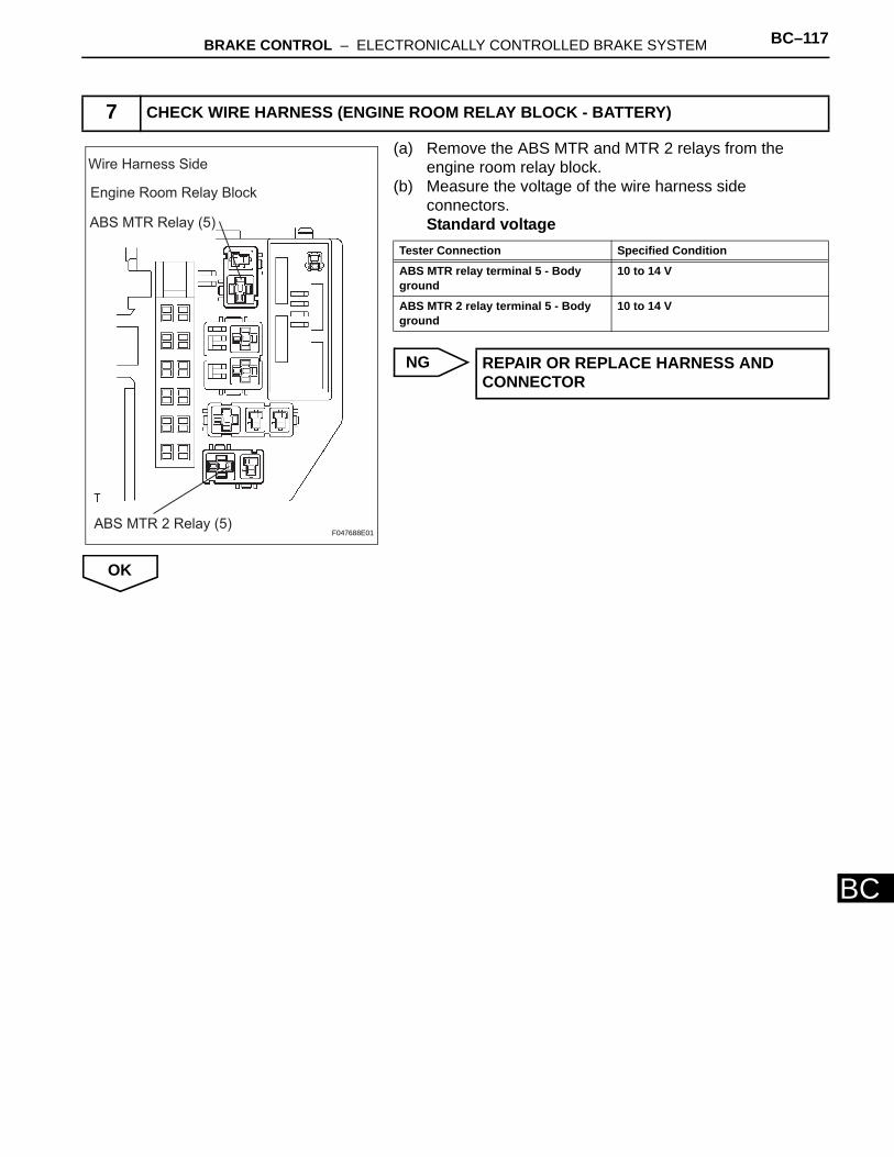
BRAKE CONTROL – ELECTRONICALLY CONTROLLED BRAKE SYSTEM BC–117
BC
(a) Remove the ABS MTR and MTR 2 relays from the engine room relay block.
(b) Measure the voltage of the wire harness side connectors.Standard voltage
NG
OK
7 CHECK WIRE HARNESS (ENGINE ROOM RELAY BLOCK - BATTERY)
Engine Room Relay Block
ABS MTR Relay (5)
ABS MTR 2 Relay (5)
Wire Harness Side
F047688E01
Tester Connection Specified Condition
ABS MTR relay terminal 5 - Body ground
10 to 14 V
ABS MTR 2 relay terminal 5 - Body ground
10 to 14 V
REPAIR OR REPLACE HARNESS AND CONNECTOR
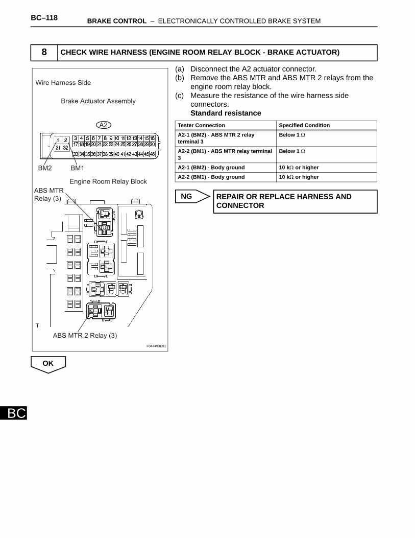
BC–118 BRAKE CONTROL – ELECTRONICALLY CONTROLLED BRAKE SYSTEM
BC
(a) Disconnect the A2 actuator connector. (b) Remove the ABS MTR and ABS MTR 2 relays from the
engine room relay block. (c) Measure the resistance of the wire harness side
connectors.Standard resistance
NG
OK
8 CHECK WIRE HARNESS (ENGINE ROOM RELAY BLOCK - BRAKE ACTUATOR)
Wire Harness Side
Brake Actuator Assembly
A2
BM2 BM1
Engine Room Relay Block
ABS MTR
Relay (3)
ABS MTR 2 Relay (3)
F047493E01
Tester Connection Specified Condition
A2-1 (BM2) - ABS MTR 2 relay terminal 3
Below 1 Ω
A2-2 (BM1) - ABS MTR relay terminal 3
Below 1 Ω
A2-1 (BM2) - Body ground 10 kΩ or higher
A2-2 (BM1) - Body ground 10 kΩ or higher
REPAIR OR REPLACE HARNESS AND CONNECTOR
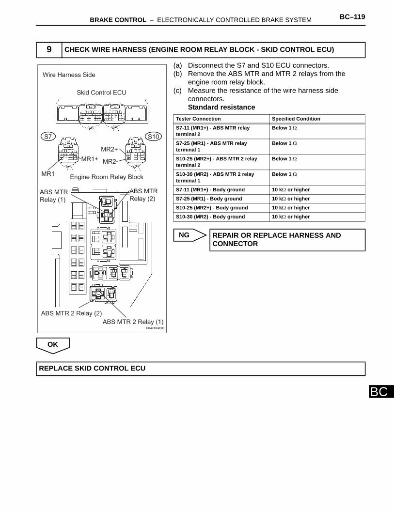
BRAKE CONTROL – ELECTRONICALLY CONTROLLED BRAKE SYSTEM BC–119
BC
(a) Disconnect the S7 and S10 ECU connectors. (b) Remove the ABS MTR and MTR 2 relays from the
engine room relay block. (c) Measure the resistance of the wire harness side
connectors.Standard resistance
NG
OK
9 CHECK WIRE HARNESS (ENGINE ROOM RELAY BLOCK - SKID CONTROL ECU)
Wire Harness Side
Skid Control ECU
MR1
MR2+
MR1+ MR2
Engine Room Relay Block
ABS MTR 2 Relay (1)
S10S7
ABS MTR 2 Relay (2)
ABS MTR
Relay (1)
ABS MTR
Relay (2)
F047494E01
Tester Connection Specified Condition
S7-11 (MR1+) - ABS MTR relay terminal 2
Below 1 Ω
S7-25 (MR1) - ABS MTR relay terminal 1
Below 1 Ω
S10-25 (MR2+) - ABS MTR 2 relay terminal 2
Below 1 Ω
S10-30 (MR2) - ABS MTR 2 relay terminal 1
Below 1 Ω
S7-11 (MR1+) - Body ground 10 kΩ or higher
S7-25 (MR1) - Body ground 10 kΩ or higher
S10-25 (MR2+) - Body ground 10 kΩ or higher
S10-30 (MR2) - Body ground 10 kΩ or higher
REPAIR OR REPLACE HARNESS AND CONNECTOR
REPLACE SKID CONTROL ECU
BC–120 BRAKE CONTROL – ELECTRONICALLY CONTROLLED BRAKE SYSTEM
BC
DESCRIPTIONThe accumulator pressure sensor is built into the actuator and detects the accumulator pressure. The skid control ECU turns on the Brake Control warning light and sounds the skid control buzzer if it senses a decrease in the accumulator pressure.
INSPECTION PROCEDURENOTICE:When replacing the skid control ECU, perform initialization of linear solenoid valve and calibration (see page BC-19).HINT:DTCs may be output if the accumulator pressure drops due to frequent braking (this is not a malfunction).
DTC C1256/57 Accumulator Low Pressure
DTC No. INF Code DTC Detection Condition Trouble Area
C1256/57 141 When either condition below is met:• Braking operation is input
when accumulator pressure is less than 12.45 MPa and vehicle speed is input (detected value changes if accumulator pressure is low after system start).
• Accumulator pressure is less than 14.62 MPa for 120 sec. (changes according to power source voltage) after system start (stores the DTC after the conditions are met, and drives buzzer).
Brake actuator assembly (accumulator pressure, accumulator pressure sensor, pump motor)
C1256/57 143 When one of following conditions is met:• Any of the wheel cylinder
pressure sensor value is lower than the target value for at least 0.5 sec. when accumulator pressure is less than 14.62 MPa and vehicle speed is input.
• Accumulator pressure changes little when accumulator pressure is less than 14.62 MPa for at least 1 sec. without braking (pump motor is operating).
• Accumulator pressure is less than 14.62 MPa for at least 0.5 sec. when motor relay is malfunctioning.
Brake actuator assembly (accumulator pressure, accumulator pressure sensor, pump motor)
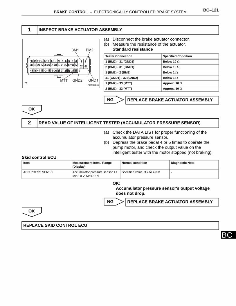
BRAKE CONTROL – ELECTRONICALLY CONTROLLED BRAKE SYSTEM BC–121
BC
(a) Disconnect the brake actuator connector. (b) Measure the resistance of the actuator.
Standard resistance
NG
OK
(a) Check the DATA LIST for proper functioning of the accumulator pressure sensor.
(b) Depress the brake pedal 4 or 5 times to operate the pump motor, and check the output value on the intelligent tester with the motor stopped (not braking).
Skid control ECU
OK:Accumulator pressure sensor's output voltage does not drop.
NG
OK
1 INSPECT BRAKE ACTUATOR ASSEMBLY
BM1 BM2
GND1GND2MTTF047491E03
Tester Connection Specified Condition
1 (BM2) - 31 (GND1) Below 10 Ω
2 (BM1) - 31 (GND1) Below 10 Ω
1 (BM2) - 2 (BM1) Below 1 Ω
31 (GND1) - 32 (GND2) Below 1 Ω
1 (BM2) - 33 (MTT) Approx. 10 Ω
2 (BM1) - 33 (MTT) Approx. 10 Ω
REPLACE BRAKE ACTUATOR ASSEMBLY
2 READ VALUE OF INTELLIGENT TESTER (ACCUMULATOR PRESSURE SENSOR)
Item Measurement Item / Range (Display)
Normal condition Diagnostic Note
ACC PRESS SENS 1 Accumulator pressure sensor 1 / Min.: 0 V, Max.: 5 V
Specified value: 3.2 to 4.0 V -
REPLACE BRAKE ACTUATOR ASSEMBLY
REPLACE SKID CONTROL ECU
BC–122 BRAKE CONTROL – ELECTRONICALLY CONTROLLED BRAKE SYSTEM
BC
DESCRIPTIONThe skid control ECU communicates with the hybrid control ECU and controls braking force according to the motor's regenerative force. The skid control ECU sends Enhanced VSC signal to the hybrid control ECU and inputs operating signal from the hybrid control ECU. The skid control ECU uses CAN communication for communication with the hybrid control ECU. If a communication malfunction is memorized, the skid control ECU prohibits Enhanced VSC operation and a part of ECB control by fail-safe function. C1259/59 is stored if the power switch is ON (READY) with the HV battery service plug disconnected.
DTC C1259/58 HV System Regenerative Malfunction
DTC C1310/51 Malfunction in HV system
DTC No. INF Code DTC Detection Condition Trouble Area
C1259/58 150 The regeneration malfunction signal is input for at least 0.02 sec. when IG2 terminal voltage is 9.5 V or more for at least 2 sec. and communication with hybrid control ECU is valid.
Hybrid control system
C1310/51 156 The traction control prohibition signal is received for at least 0.07 sec. when IG2 terminal voltage is 10.5 V or more for at least 1.5 sec. and communication with hybrid control ECU is valid.
Hybrid control system (Enhanced VSC)
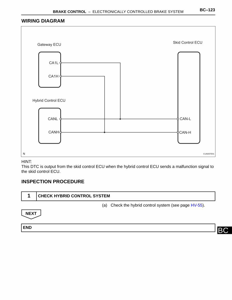
BRAKE CONTROL – ELECTRONICALLY CONTROLLED BRAKE SYSTEM BC–123
BC
WIRING DIAGRAM
HINT:This DTC is output from the skid control ECU when the hybrid control ECU sends a malfunction signal to the skid control ECU.
INSPECTION PROCEDURE
(a) Check the hybrid control system (see page HV-55).
NEXT
1 CHECK HYBRID CONTROL SYSTEM
Gateway ECUSkid Control ECU
CA1L
CA1H
CANL
CANH
Hybrid Control ECU
CAN-L
CAN-H
C126257E01
END
BC–124 BRAKE CONTROL – ELECTRONICALLY CONTROLLED BRAKE SYSTEM
BC
DESCRIPTIONThe skid control ECU outputs this DTC if malfunctions are found in the circuit inside the computer by self-diagnosis.
INSPECTION PROCEDURENOTICE:When replacing the skid control ECU, perform initialization of linear solenoid valve and calibration (see page BC-19).
(a) Clear the DTCs (see page BC-38). (b) Turn the power switch ON (READY). (c) Check the same DTCs are recorded (see page BC-38).
Result
B
A
DTC C1300 Skid Control ECU Malfunction
DTC No. INF Code DTC Detecting Condition Trouble Area
C1300/- - Malfunction in skid control ECU Skid control ECU
1 CHECK DTC
Result Proceed to
DTC is output A
DTC is not output B
PROCEED TO NEXT CIRCUIT INSPECTION SHOWN IN PROBLEMS TABLE
REPLACE SKID CONTROL ECU
BRAKE CONTROL – ELECTRONICALLY CONTROLLED BRAKE SYSTEM BC–125
BC
DESCRIPTIONABS main relay 1 (ABS NO. 1 relay) supplies power to the changeover solenoid and the linear solenoid. ABS main relay 2 (ABS NO. 2 relay) goes on for approximately 5 seconds after the power switch is turned off and the braking effort signal input is terminated. ABS main relay 2 (ABS NO. 2 relay) supplies electricity and maintains operating condition for the brake system when the power switch is OFF.
DTC C1311/11 Open in Main Relay 1 Circuit
DTC C1312/12 Short in Main Relay 1 Circuit
DTC C1313/13 Open in Main Relay 2 Circuit
DTC C1314/14 Short in Main Relay 2 Circuit
DTC No. INF Code DTC Detection Condition Trouble Area
C1311/11 1 When either condition below is met:• Relay contact is off (BS 1
terminal is less than 3.5 V) for at least 0.2 sec. when R1+ terminal voltage is 9.5 V or more and main relay 1 is on.
• R1+ terminal voltage is less than 9.5 V and main relay 1 cannot be on for at least 0.2 sec. when main relay 1 is turned on (BS 1 terminal is 3.5 V or more).
• ABS main relay 1 (ABS NO. 1 relay)
• Skid control ECU • Harness and connector
C1312/12 3 Relay contact is on for at least 4 sec. when main relay 1 is off.
• ABS main relay 1 (ABS NO. 1 relay)
• Skid control ECU • Harness and connector
C1313/13 4 When either condition below is met:• Relay contact is off (BS2
terminal is less than 3.5 V) for at least 0.2 sec. when R2+ terminal voltage is 9.5 V or more and main relay 2 is on.
• R2+ terminal voltage is less than 9.5 V and main relay 2 cannot be on for at least 2 sec. when main relay 2 is turned on (BS 1 terminal is 3.5 V or more).
• ABS main relay 2 (ABS NO. 2 relay)
• Skid control ECU • Harness and connector
C1314/14 6 Relay contact is on for at least 4 sec. when main relay 2 is off.
• ABS main relay 2 (ABS NO. 2 relay)
• Skid control ECU • Harness and connector
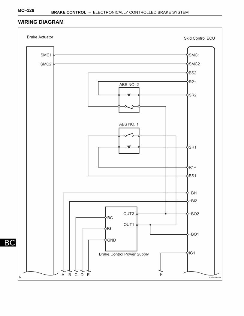
BC–126 BRAKE CONTROL – ELECTRONICALLY CONTROLLED BRAKE SYSTEM
BC
WIRING DIAGRAM
Brake Actuator
SMC1
SMC2
Skid Control ECU
SMC1
SMC2
BS2
R2+
SR2
SR1
R1+
BS1
+BI1
+BI2
+BO2
+BO1
IG1
ABS NO. 2
ABS NO. 1
Brake Control Power Supply
BC
IG
GND
OUT2
OUT1
A B C D E FC126258E01

BRAKE CONTROL – ELECTRONICALLY CONTROLLED BRAKE SYSTEM BC–127
BC
A B C D E F
ECU-IG
IG1
AM1
IG2
Power Source
Control ECU
AM2IG2D
AM1
IG1D
AM2 P/I
DC/DC
ABS MAIN3
ABS MAIN2
ABS MAIN1
A B C D E C126250E01
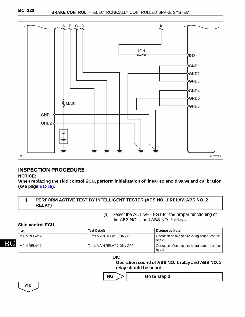
BC–128 BRAKE CONTROL – ELECTRONICALLY CONTROLLED BRAKE SYSTEM
BC
INSPECTION PROCEDURENOTICE:When replacing the skid control ECU, perform initialization of linear solenoid valve and calibration (see page BC-19).
(a) Select the ACTIVE TEST for the proper functioning of the ABS NO. 1 and ABS NO. 2 relays.
Skid control ECU
OK:Operation sound of ABS NO. 1 relay and ABS NO. 2 relay should be heard.
NG
OK
1 PERFORM ACTIVE TEST BY INTELLIGENT TESTER (ABS NO. 1 RELAY, ABS NO. 2 RELAY)
A B C D
MAIN
GND1
GND2
IGN
E
IG2
GND1
GND2
GND3
GND4
GND5
GND6
C126259E01
Item Test Details Diagnostic Note
MAIN RELAY 2 Turns MAIN RELAY 1 ON / OFF Operation of solenoid (clicking sound) can be heard
MAIN RELAY 1 Turns MAIN RELAY 2 ON / OFF Operation of solenoid (clicking sound) can be heard
Go to step 3
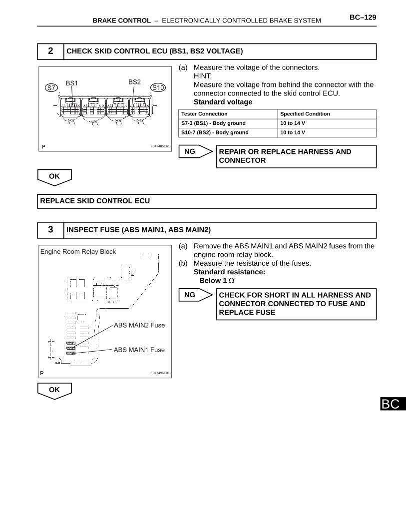
BRAKE CONTROL – ELECTRONICALLY CONTROLLED BRAKE SYSTEM BC–129
BC
(a) Measure the voltage of the connectors.HINT:Measure the voltage from behind the connector with the connector connected to the skid control ECU.Standard voltage
NG
OK
(a) Remove the ABS MAIN1 and ABS MAIN2 fuses from the engine room relay block.
(b) Measure the resistance of the fuses.Standard resistance:
Below 1 Ω
NG
OK
2 CHECK SKID CONTROL ECU (BS1, BS2 VOLTAGE)
BS1 BS2S7 S10
F047485E61
Tester Connection Specified Condition
S7-3 (BS1) - Body ground 10 to 14 V
S10-7 (BS2) - Body ground 10 to 14 V
REPAIR OR REPLACE HARNESS AND CONNECTOR
REPLACE SKID CONTROL ECU
3 INSPECT FUSE (ABS MAIN1, ABS MAIN2)
Engine Room Relay Block
ABS MAIN2 Fuse
ABS MAIN1 Fuse
F047495E01
CHECK FOR SHORT IN ALL HARNESS AND CONNECTOR CONNECTED TO FUSE AND REPLACE FUSE
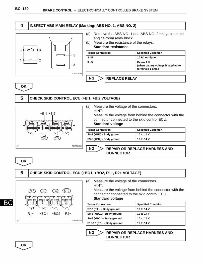
BC–130 BRAKE CONTROL – ELECTRONICALLY CONTROLLED BRAKE SYSTEM
BC
(a) Remove the ABS NO. 1 and ABS NO. 2 relays from the engine room relay block.
(b) Measure the resistance of the relays.Standard resistance
NG
OK
(a) Measure the voltage of the connectors.HINT:Measure the voltage from behind the connector with the connector connected to the skid control ECU.Standard voltage
NG
OK
(a) Measure the voltage of the connectors.HINT:Measure the voltage from behind the connector with the connector connected to the skid control ECU.Standard voltage
NG
OK
4 INSPECT ABS MAIN RELAY (Marking: ABS NO. 1, ABS NO. 2)
1
1
2
2
3
3
5
5
B060778E30
Tester Connection Specified Condition
3 - 5 10 kΩ or higher
3 - 5 Below 1 Ω(when battery voltage is applied to terminals 1 and 2
REPLACE RELAY
5 CHECK SKID CONTROL ECU (+BI1, +BI2 VOLTAGE)
+BI1 +BI2
S8 S9
F047485E62
Tester Connection Specified Condition
S8-3 (+BI1) - Body ground 10 to 14 V
S9-5 (+BI2) - Body ground 10 to 14 V
REPAIR OR REPLACE HARNESS AND CONNECTOR
6 CHECK SKID CONTROL ECU (+BO1, +BO2, R1+, R2+ VOLTAGE)
S7 S8 S9 S10
R1+ +BO1 +BO2 R2+
F047485E63
Tester Connection Specified Condition
S7-2 (R1+) - Body ground 10 to 14 V
S8-5 (+BO1) - Body ground 10 to 14 V
S9-4 (+BO2) - Body ground 10 to 14 V
S10-17 (R2+) - Body ground 10 to 14 V
REPAIR OR REPLACE HARNESS AND CONNECTOR
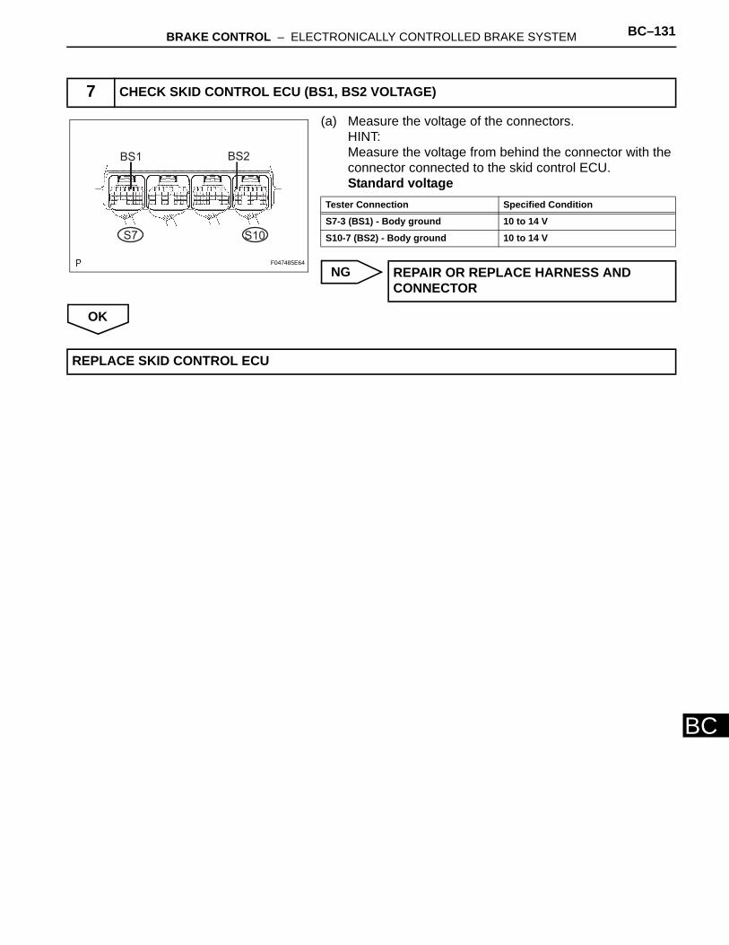
BRAKE CONTROL – ELECTRONICALLY CONTROLLED BRAKE SYSTEM BC–131
BC
(a) Measure the voltage of the connectors.HINT:Measure the voltage from behind the connector with the connector connected to the skid control ECU.Standard voltage
NG
OK
7 CHECK SKID CONTROL ECU (BS1, BS2 VOLTAGE)
BS1 BS2
S7 S10
F047485E64
Tester Connection Specified Condition
S7-3 (BS1) - Body ground 10 to 14 V
S10-7 (BS2) - Body ground 10 to 14 V
REPAIR OR REPLACE HARNESS AND CONNECTOR
REPLACE SKID CONTROL ECU
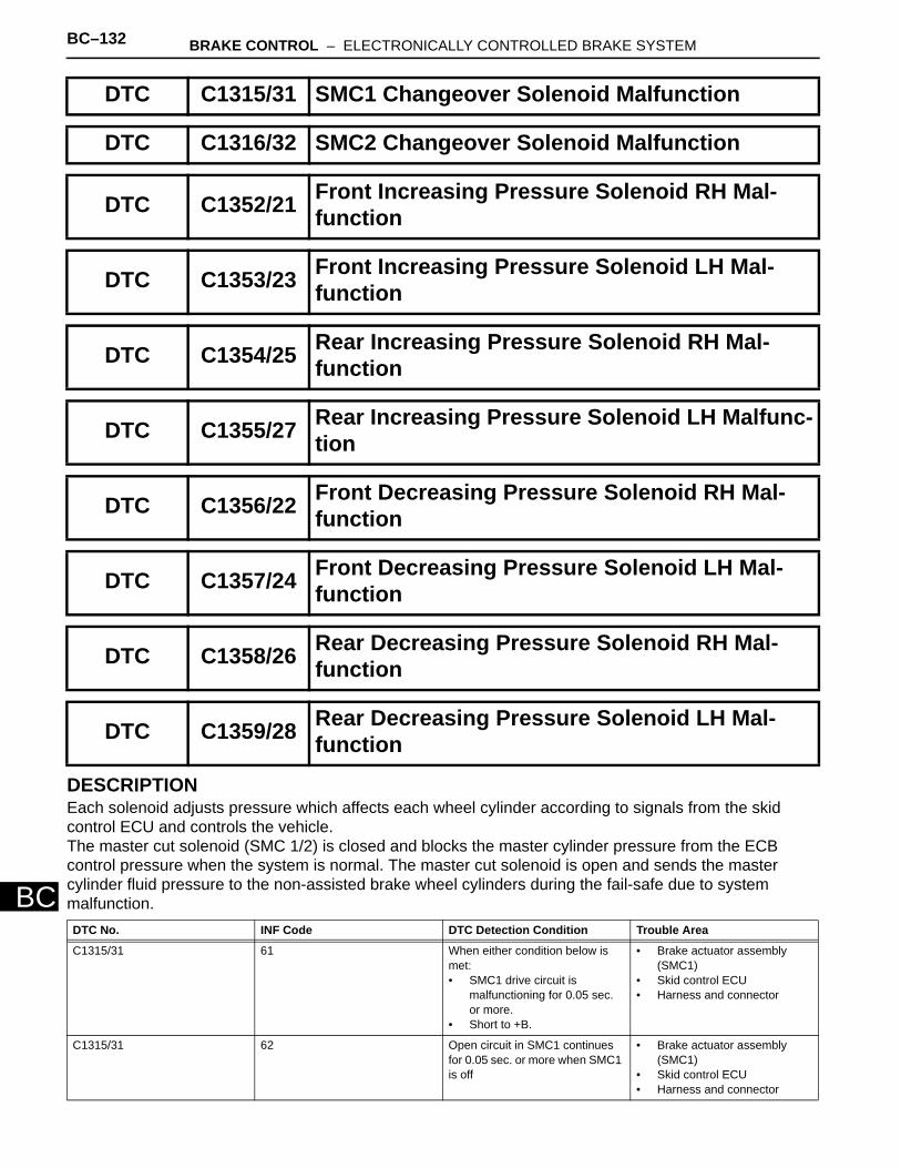
BC–132 BRAKE CONTROL – ELECTRONICALLY CONTROLLED BRAKE SYSTEM
BC
DESCRIPTIONEach solenoid adjusts pressure which affects each wheel cylinder according to signals from the skid control ECU and controls the vehicle. The master cut solenoid (SMC 1/2) is closed and blocks the master cylinder pressure from the ECB control pressure when the system is normal. The master cut solenoid is open and sends the master cylinder fluid pressure to the non-assisted brake wheel cylinders during the fail-safe due to system malfunction.
DTC C1315/31 SMC1 Changeover Solenoid Malfunction
DTC C1316/32 SMC2 Changeover Solenoid Malfunction
DTC C1352/21 Front Increasing Pressure Solenoid RH Mal-function
DTC C1353/23 Front Increasing Pressure Solenoid LH Mal-function
DTC C1354/25 Rear Increasing Pressure Solenoid RH Mal-function
DTC C1355/27 Rear Increasing Pressure Solenoid LH Malfunc-tion
DTC C1356/22 Front Decreasing Pressure Solenoid RH Mal-function
DTC C1357/24 Front Decreasing Pressure Solenoid LH Mal-function
DTC C1358/26 Rear Decreasing Pressure Solenoid RH Mal-function
DTC C1359/28 Rear Decreasing Pressure Solenoid LH Mal-function
DTC No. INF Code DTC Detection Condition Trouble Area
C1315/31 61 When either condition below is met:• SMC1 drive circuit is
malfunctioning for 0.05 sec. or more.
• Short to +B.
• Brake actuator assembly (SMC1)
• Skid control ECU• Harness and connector
C1315/31 62 Open circuit in SMC1 continues for 0.05 sec. or more when SMC1 is off
• Brake actuator assembly (SMC1)
• Skid control ECU• Harness and connector
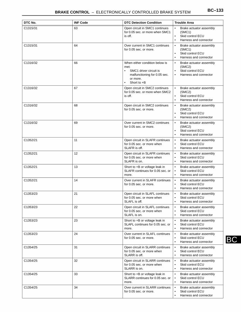
BRAKE CONTROL – ELECTRONICALLY CONTROLLED BRAKE SYSTEM BC–133
BC
C1315/31 63 Open circuit in SMC1 continues for 0.05 sec. or more when SMC1 is off.
• Brake actuator assembly (SMC1)
• Skid control ECU• Harness and connector
C1315/31 64 Over current in SMC1 continues for 0.05 sec. or more.
• Brake actuator assembly (SMC1)
• Skid control ECU• Harness and connector
C1316/32 66 When either condition below is met:• SMC1 driver circuit is
malfunctioning for 0.05 sec. or more.
• Short to +B
• Brake actuator assembly (SMC2)
• Skid control ECU• Harness and connector
C1316/32 67 Open circuit in SMC2 continues for 0.05 sec. or more when SMC2 is off.
• Brake actuator assembly (SMC2)
• Skid control ECU• Harness and connector
C1316/32 68 Open circuit in SMC2 continues for 0.05 sec. or more.
• Brake actuator assembly (SMC2)
• Skid control ECU• Harness and connector
C1316/32 69 Over current in SMC2 continues for 0.05 sec. or more.
• Brake actuator assembly (SMC2)
• Skid control ECU• Harness and connector
C1352/21 11 Open circuit in SLAFR continues for 0.05 sec. or more when SLAFR is off.
• Brake actuator assembly• Skid control ECU• Harness and connector
C1352/21 12 Open circuit in SLAFR continues for 0.05 sec. or more when SLAFR is on.
• Brake actuator assembly• Skid control ECU• Harness and connector
C1352/21 13 Short to +B or voltage leak in SLAFR continues for 0.05 sec. or more.
• Brake actuator assembly• Skid control ECU• Harness and connector
C1352/21 14 Over current in SLAFR continues for 0.05 sec. or more.
• Brake actuator assembly • Skid control ECU• Harness and connector
C1353/23 21 Open circuit in SLAFL continues for 0.05 sec. or more when SLAFL is off.
• Brake actuator assembly• Skid control ECU• Harness and connector
C1353/23 22 Open circuit in SLAFL continues for 0.05 sec. or more when SLAFL is on.
• Brake actuator assembly• Skid control ECU• Harness and connector
C1353/23 23 Short to +B or voltage leak in SLAFL continues for 0.05 sec. or more.
• Brake actuator assembly• Skid control ECU• Harness and connector
C1353/23 24 Over current in SLAFL continues for 0.05 sec. or more.
• Brake actuator assembly• Skid control ECU• Harness and connector
C1354/25 31 Open circuit in SLARR continues for 0.05 sec. or more when SLARR is off.
• Brake actuator assembly• Skid control ECU• Harness and connector
C1354/25 32 Open circuit in SLARR continues for 0.05 sec. or more when SLARR is on.
• Brake actuator assembly• Skid control ECU• Harness and connector
C1354/25 33 Short to +B or voltage leak in SLARR continues for 0.05 sec. or more.
• Brake actuator assembly• Skid control ECU• Harness and connector
C1354/25 34 Over current in SLARR continues for 0.05 sec. or more.
• Brake actuator assembly• Skid control ECU• Harness and connector
DTC No. INF Code DTC Detection Condition Trouble Area
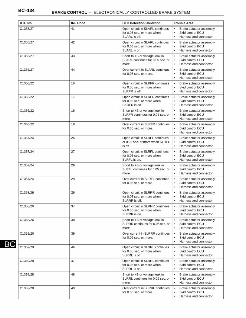
BC–134 BRAKE CONTROL – ELECTRONICALLY CONTROLLED BRAKE SYSTEM
BC
C1355/27 41 Open circuit in SLARL continues for 0.05 sec. or more when SLARL is off.
• Brake actuator assembly• Skid control ECU• Harness and connector
C1355/27 42 Open circuit in SLARL continues for 0.05 sec. or more when SLARL is on.
• Brake actuator assembly• Skid control ECU• Harness and connector
C1355/27 43 Short to +B or voltage leak in SLARL continues for 0.05 sec. or more.
• Brake actuator assembly• Skid control ECU• Harness and connector
C1355/27 44 Over current in SLARL continues for 0.05 sec. or more.
• Brake actuator assembly• Skid control ECU• Harness and connector
C1356/22 16 Open circuit in SLRFR continues for 0.05 sec. or more when SLRFR is off.
• Brake actuator assembly• Skid control ECU• Harness and connector
C1356/22 17 Open circuit in SLRFR continues for 0.05 sec. or more when SKRFR is on.
• Brake actuator assembly• Skid control ECU• Harness and connector
C1356/22 18 Short to +B or voltage leak in SLRFR continues for 0.05 sec. or more.
• Brake actuator assembly• Skid control ECU• Harness and connector
C1356/22 19 Over current in SLRFR continues for 0.05 sec. or more.
• Brake actuator assembly• Skid control ECU• Harness and connector
C1357/24 26 Open circuit in SLRFL continues or 0.05 sec. or more when SLRFL is off.
• Brake actuator assembly• Skid control ECU• Harness and connector
C1357/24 27 Open circuit in SLRFL continues for 0.05 sec. or more when SLRFL is on.
• Brake actuator assembly• Skid control ECU• Harness and connector
C1357/24 28 Short to +B or voltage leak in SLRFL continues for 0.05 sec. or more.
• Brake actuator assembly• Skid control ECU• Harness and connector
C1357/24 29 Over current in SLRFL continues for 0.05 sec. or more.
• Brake actuator assembly• Skid control ECU• Harness and connector
C1358/26 36 Open circuit in SLRRR continues for 0.05 sec. or more when SLRRR is off.
• Brake actuator assembly• Skid control ECU• Harness and connector
C1358/26 37 Open circuit in SLRRR continues for 0.05 sec. or more when SLRRR is on.
• Brake actuator assembly• Skid control ECU• Harness and connector
C1358/26 38 Short to +B or voltage leak in SLRRR continues for 0.05 sec. or more.
• Brake actuator assembly• Skid control ECU• Harness and connector
C1358/26 39 Over current in SLRRR continues for 0.05 sec. or more.
• Brake actuator assembly• Skid control ECU• Harness and connector
C1359/28 46 Open circuit in SLRRL continues for 0.05 sec. or more when SLRRL is off.
• Brake actuator assembly• Skid control ECU• Harness and connector
C1359/28 47 Open circuit in SLRRL continues for 0.05 sec. or more when SLRRL is on.
• Brake actuator assembly• Skid control ECU• Harness and connector
C1359/28 48 Short to +B or voltage leak in SLRRL continues for 0.05 sec. or more.
• Brake actuator assembly• Skid control ECU• Harness and connector
C1359/28 49 Over current in SLRRL continues for 0.05 sec. or more.
• Brake actuator assembly• Skid control ECU• Harness and connector
DTC No. INF Code DTC Detection Condition Trouble Area
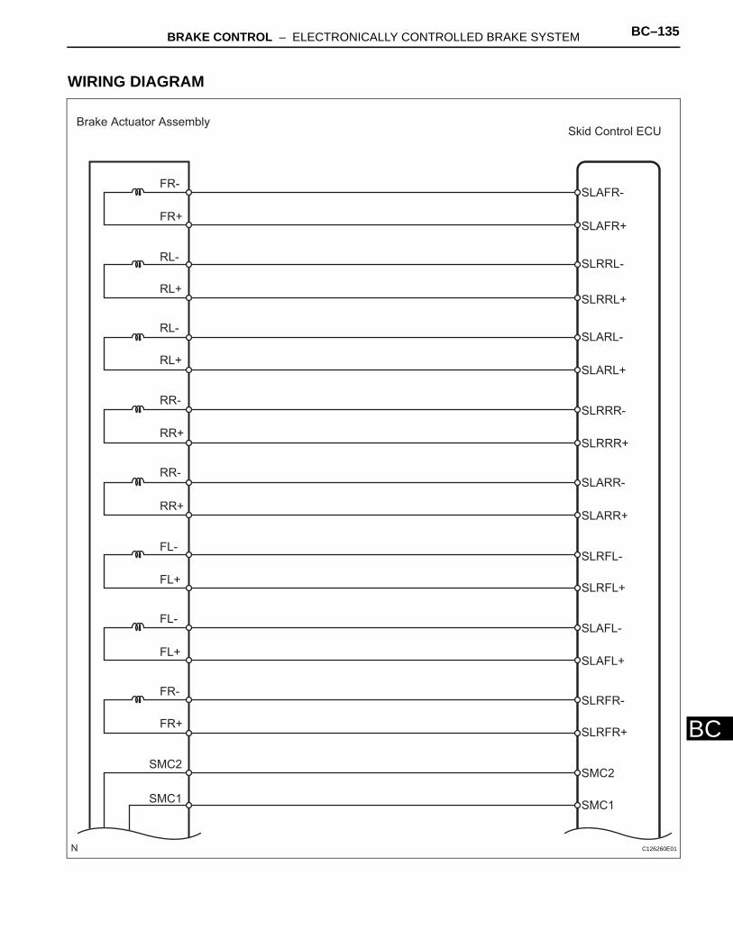
BRAKE CONTROL – ELECTRONICALLY CONTROLLED BRAKE SYSTEM BC–135
BC
WIRING DIAGRAM
Brake Actuator AssemblySkid Control ECU
FR-
FR+
RL-
RL+
RL-
RL+
RR-
RR+
FL-
FL+
FL-
FL+
FR-
SMC2
SMC1
RR-
RR+
FR+
SLAFR-
SLAFR+
SLRRL-
SLRRL+
SLARL-
SLARL+
SLRRR-
SLRRR+
SLARR-
SLARR+
SLRFL-
SLRFL+
SLAFL+
SLAFL-
SLRFR+
SLRFR-
SMC2
SMC1
C126260E01
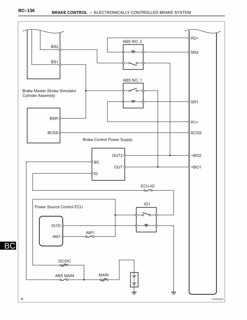
BC–136 BRAKE CONTROL – ELECTRONICALLY CONTROLLED BRAKE SYSTEM
BC
BS2
BS1
Brake Master Stroke Simulator
Cylinder Assembly
BSR
BCSS
Brake Control Power Supply
BC
IG
OUT2
OUT
ABS NO. 2
ABS NO. 1
R2+
SR2
SR1
R1+
SCSS
+BO2
+BO1
ECU-IG
IG1Power Source Control ECU
IG1D
AM1AM1
MAIN
DC/DC
ABS MAIN
C126261E01
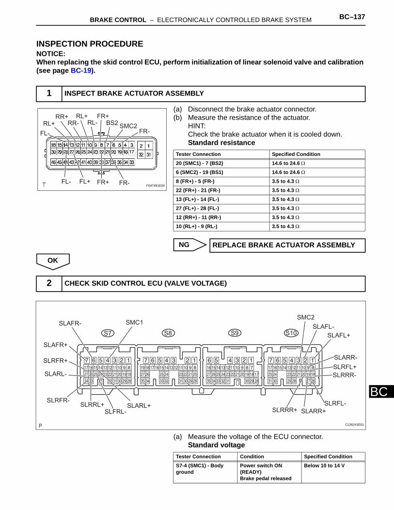
BRAKE CONTROL – ELECTRONICALLY CONTROLLED BRAKE SYSTEM BC–137
BC
INSPECTION PROCEDURENOTICE:When replacing the skid control ECU, perform initialization of linear solenoid valve and calibration (see page BC-19).
(a) Disconnect the brake actuator connector. (b) Measure the resistance of the actuator.
HINT:Check the brake actuator when it is cooled down.Standard resistance
NG
OK
(a) Measure the voltage of the ECU connector.Standard voltage
1 INSPECT BRAKE ACTUATOR ASSEMBLY
FL-
RL+RR+RR- RL-RL+
FR+BS2
SMC2FR-
FL- FL+ FR+ FR- F047491E04
Tester Connection Specified Condition
20 (SMC1) - 7 (BS2) 14.6 to 24.6 Ω
6 (SMC2) - 19 (BS1) 14.6 to 24.6 Ω
8 (FR+) - 5 (FR-) 3.5 to 4.3 Ω
22 (FR+) - 21 (FR-) 3.5 to 4.3 Ω
13 (FL+) - 14 (FL-) 3.5 to 4.3 Ω
27 (FL+) - 28 (FL-) 3.5 to 4.3 Ω
12 (RR+) - 11 (RR-) 3.5 to 4.3 Ω
10 (RL+) - 9 (RL-) 3.5 to 4.3 Ω
REPLACE BRAKE ACTUATOR ASSEMBLY
2 CHECK SKID CONTROL ECU (VALVE VOLTAGE)
S7 S9 S10S8
SLAFR-
SLAFR+
SLRFR+
SLARL-
SLRFR-SLRRL+ SLARL+
SLFRL-
SMC1SMC2
SLAFL-
SLAFL+
SLARR-
SLRFL+
SLRRR-
SLARR+
SLRFL-SLRRR+
C126241E01
Tester Connection Condition Specified Condition
S7-4 (SMC1) - Body ground
Power switch ON (READY) Brake pedal released
Below 10 to 14 V
BC–138 BRAKE CONTROL – ELECTRONICALLY CONTROLLED BRAKE SYSTEM
BCHINT:*: Refer to waveform 5 of "TERMINALS OF ECU" (see page BC-29).
NG
S10-3 (SMC2) - Body ground
Power switch ON (READY) Brake pedal released
Below 10 to 14 V
S7-7 (SLAFR+) - Body ground
Power switch ON (READY) Brake pedal released
Pulse generation*
S7-6 (SLAFR-) - Body ground
Power switch ON (READY) Brake pedal released
Pulse generation*
S10-1 (SLAFL+) - Body ground
Power switch ON (READY) Brake pedal released
Pulse generation*
S10-2 (SLAFL-) - Body ground
Power switch ON (READY) Brake pedal released
Pulse generation*
S10-19 (SLARR+) - Body ground
Power switch ON (READY) Brake pedal released
Pulse generation*
S10-9 (SLARR-) - Body ground
Power switch ON (READY) Brake pedal released
Pulse generation*
S7-15 (SLARL+) - Body ground
Power switch ON (READY) Brake pedal released
Pulse generation*
S7-27 (SLARL-) - Body ground
Power switch ON (READY) Brake pedal released
Pulse generation*
S7-17 (SLRFR+) - Body ground
Power switch ON (READY) Brake pedal released
Below 1.5 V
S10-8 (SLRFL+) - Body ground
Power switch ON (READY) Brake pedal released
Below 1.5 V
S10-20 (SLRRR+) - Body ground
Power switch ON (READY) Brake pedal released
Below 1.5 V
S7-16 (SLRRL+) - Body ground
Power switch ON (READY) Brake pedal released
Below 1.5 V
S7-34 (SLRFR-) - Body ground
Power switch ON (READY)
Below 1.5 V
S10-26 (SLRFL-) - Body ground
Power switch ON (READY) Brake pedal released
Below 1.5 V
S10-18 (SLRRR-) - Body ground
Power switch ON (READY) Brake pedal released
Below 1.5 V
S7-26 (SLRRL-) - Body ground
Power switch ON (READY) Brake pedal released
Below 1.5 V
REPAIR OR REPLACE HARNESS AND CONNECTOR
Tester Connection Condition Specified Condition
BRAKE CONTROL – ELECTRONICALLY CONTROLLED BRAKE SYSTEM BC–139
BC
OK
REPLACE SKID CONTROL ECU
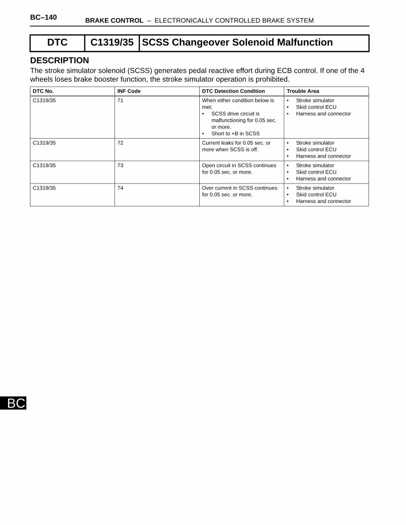
BC–140 BRAKE CONTROL – ELECTRONICALLY CONTROLLED BRAKE SYSTEM
BC
DESCRIPTIONThe stroke simulator solenoid (SCSS) generates pedal reactive effort during ECB control. If one of the 4 wheels loses brake booster function, the stroke simulator operation is prohibited.
DTC C1319/35 SCSS Changeover Solenoid Malfunction
DTC No. INF Code DTC Detection Condition Trouble Area
C1319/35 71 When either condition below is met:• SCSS drive circuit is
malfunctioning for 0.05 sec. or more.
• Short to +B in SCSS
• Stroke simulator• Skid control ECU • Harness and connector
C1319/35 72 Current leaks for 0.05 sec. or more when SCSS is off.
• Stroke simulator• Skid control ECU • Harness and connector
C1319/35 73 Open circuit in SCSS continues for 0.05 sec. or more.
• Stroke simulator• Skid control ECU• Harness and connector
C1319/35 74 Over current in SCSS continues for 0.05 sec. or more.
• Stroke simulator• Skid control ECU• Harness and connector
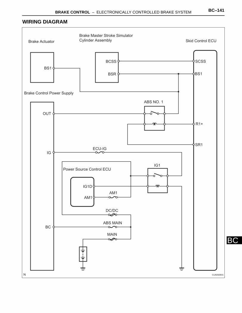
BRAKE CONTROL – ELECTRONICALLY CONTROLLED BRAKE SYSTEM BC–141
BC
WIRING DIAGRAM
Brake Actuator
Brake Master Stroke Simulator
Cylinder Assembly
BS1
BCSS
BSR
SCSS
BS1
ABS NO. 1
R1+
SR1
Brake Control Power Supply
OUT
IG
BC
Power Source Control ECU
IG1D
AM1
AM1
DC/DC
ABS MAIN
MAIN
ECU-IG
IG1
Skid Control ECU
C126262E01
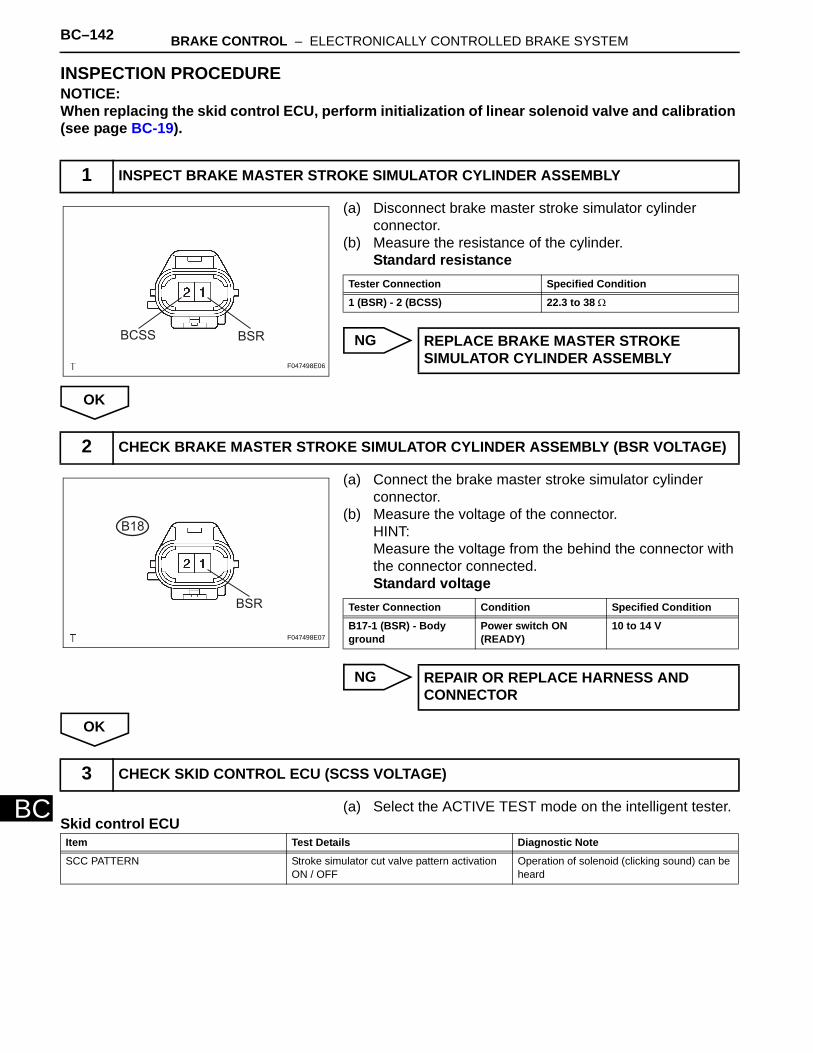
BC–142 BRAKE CONTROL – ELECTRONICALLY CONTROLLED BRAKE SYSTEM
BC
INSPECTION PROCEDURENOTICE:When replacing the skid control ECU, perform initialization of linear solenoid valve and calibration (see page BC-19).
(a) Disconnect brake master stroke simulator cylinder connector.
(b) Measure the resistance of the cylinder.Standard resistance
NG
OK
(a) Connect the brake master stroke simulator cylinder connector.
(b) Measure the voltage of the connector.HINT:Measure the voltage from the behind the connector with the connector connected.Standard voltage
NG
OK
(a) Select the ACTIVE TEST mode on the intelligent tester.Skid control ECU
1 INSPECT BRAKE MASTER STROKE SIMULATOR CYLINDER ASSEMBLY
BCSS BSR
F047498E06
Tester Connection Specified Condition
1 (BSR) - 2 (BCSS) 22.3 to 38 Ω
REPLACE BRAKE MASTER STROKE SIMULATOR CYLINDER ASSEMBLY
2 CHECK BRAKE MASTER STROKE SIMULATOR CYLINDER ASSEMBLY (BSR VOLTAGE)
BSR
B18
F047498E07
Tester Connection Condition Specified Condition
B17-1 (BSR) - Body ground
Power switch ON(READY)
10 to 14 V
REPAIR OR REPLACE HARNESS AND CONNECTOR
3 CHECK SKID CONTROL ECU (SCSS VOLTAGE)
Item Test Details Diagnostic Note
SCC PATTERN Stroke simulator cut valve pattern activation ON / OFF
Operation of solenoid (clicking sound) can be heard
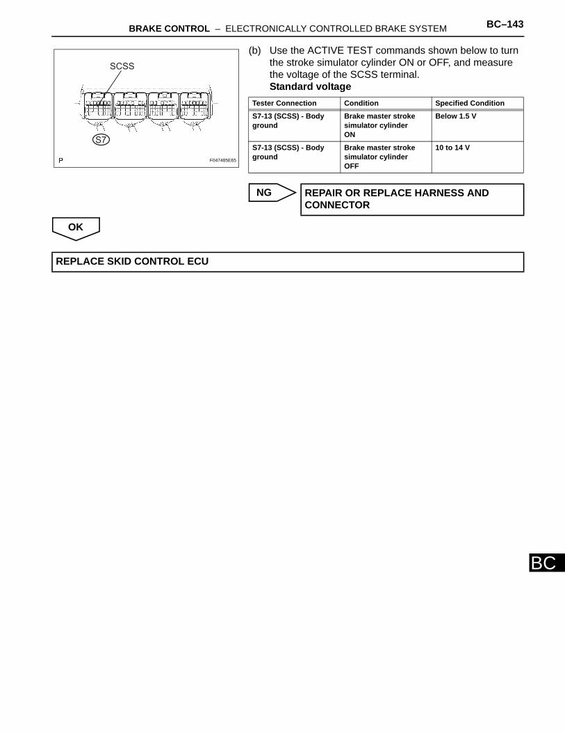
BRAKE CONTROL – ELECTRONICALLY CONTROLLED BRAKE SYSTEM BC–143
BC
(b) Use the ACTIVE TEST commands shown below to turn the stroke simulator cylinder ON or OFF, and measure the voltage of the SCSS terminal.Standard voltage
NG
OK
SCSS
S7
F047485E65
Tester Connection Condition Specified Condition
S7-13 (SCSS) - Body ground
Brake master stroke simulator cylinderON
Below 1.5 V
S7-13 (SCSS) - Body ground
Brake master stroke simulator cylinderOFF
10 to 14 V
REPAIR OR REPLACE HARNESS AND CONNECTOR
REPLACE SKID CONTROL ECU
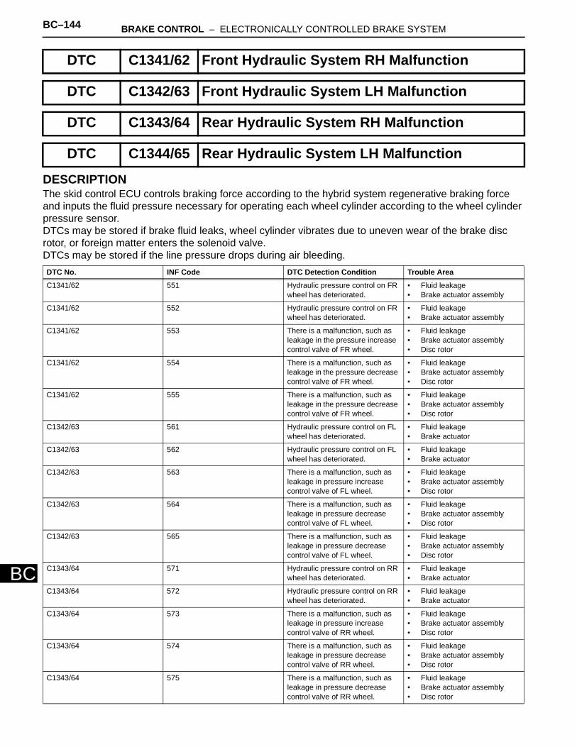
BC–144 BRAKE CONTROL – ELECTRONICALLY CONTROLLED BRAKE SYSTEM
BC
DESCRIPTIONThe skid control ECU controls braking force according to the hybrid system regenerative braking force and inputs the fluid pressure necessary for operating each wheel cylinder according to the wheel cylinder pressure sensor. DTCs may be stored if brake fluid leaks, wheel cylinder vibrates due to uneven wear of the brake disc rotor, or foreign matter enters the solenoid valve. DTCs may be stored if the line pressure drops during air bleeding.
DTC C1341/62 Front Hydraulic System RH Malfunction
DTC C1342/63 Front Hydraulic System LH Malfunction
DTC C1343/64 Rear Hydraulic System RH Malfunction
DTC C1344/65 Rear Hydraulic System LH Malfunction
DTC No. INF Code DTC Detection Condition Trouble Area
C1341/62 551 Hydraulic pressure control on FR wheel has deteriorated.
• Fluid leakage • Brake actuator assembly
C1341/62 552 Hydraulic pressure control on FR wheel has deteriorated.
• Fluid leakage • Brake actuator assembly
C1341/62 553 There is a malfunction, such as leakage in the pressure increase control valve of FR wheel.
• Fluid leakage • Brake actuator assembly • Disc rotor
C1341/62 554 There is a malfunction, such as leakage in the pressure decrease control valve of FR wheel.
• Fluid leakage • Brake actuator assembly • Disc rotor
C1341/62 555 There is a malfunction, such as leakage in the pressure decrease control valve of FR wheel.
• Fluid leakage • Brake actuator assembly • Disc rotor
C1342/63 561 Hydraulic pressure control on FL wheel has deteriorated.
• Fluid leakage • Brake actuator
C1342/63 562 Hydraulic pressure control on FL wheel has deteriorated.
• Fluid leakage • Brake actuator
C1342/63 563 There is a malfunction, such as leakage in pressure increase control valve of FL wheel.
• Fluid leakage • Brake actuator assembly • Disc rotor
C1342/63 564 There is a malfunction, such as leakage in pressure decrease control valve of FL wheel.
• Fluid leakage • Brake actuator assembly • Disc rotor
C1342/63 565 There is a malfunction, such as leakage in pressure decrease control valve of FL wheel.
• Fluid leakage • Brake actuator assembly • Disc rotor
C1343/64 571 Hydraulic pressure control on RR wheel has deteriorated.
• Fluid leakage • Brake actuator
C1343/64 572 Hydraulic pressure control on RR wheel has deteriorated.
• Fluid leakage • Brake actuator
C1343/64 573 There is a malfunction, such as leakage in pressure increase control valve of RR wheel.
• Fluid leakage • Brake actuator assembly • Disc rotor
C1343/64 574 There is a malfunction, such as leakage in pressure decrease control valve of RR wheel.
• Fluid leakage • Brake actuator assembly • Disc rotor
C1343/64 575 There is a malfunction, such as leakage in pressure decrease control valve of RR wheel.
• Fluid leakage • Brake actuator assembly • Disc rotor
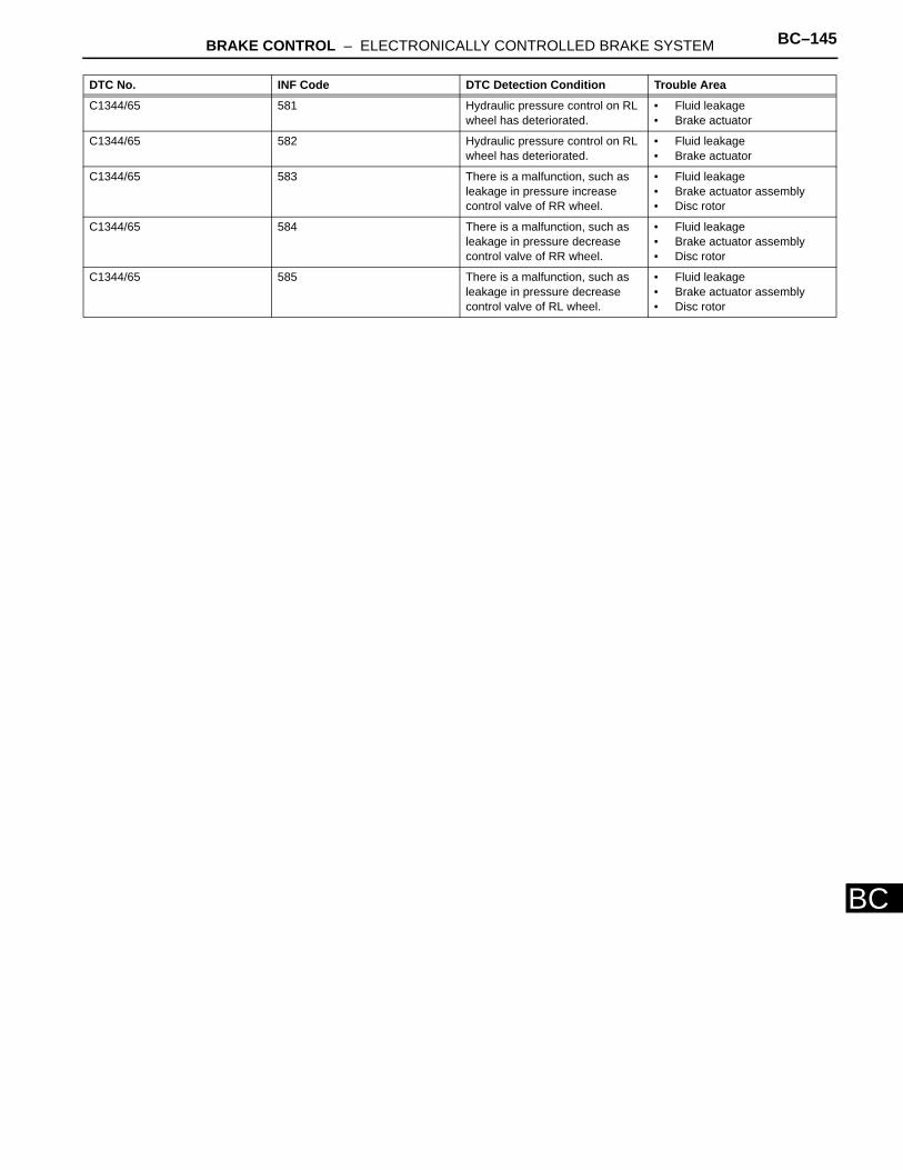
BRAKE CONTROL – ELECTRONICALLY CONTROLLED BRAKE SYSTEM BC–145
BC
C1344/65 581 Hydraulic pressure control on RL wheel has deteriorated.
• Fluid leakage • Brake actuator
C1344/65 582 Hydraulic pressure control on RL wheel has deteriorated.
• Fluid leakage • Brake actuator
C1344/65 583 There is a malfunction, such as leakage in pressure increase control valve of RR wheel.
• Fluid leakage • Brake actuator assembly • Disc rotor
C1344/65 584 There is a malfunction, such as leakage in pressure decrease control valve of RR wheel.
• Fluid leakage • Brake actuator assembly • Disc rotor
C1344/65 585 There is a malfunction, such as leakage in pressure decrease control valve of RL wheel.
• Fluid leakage • Brake actuator assembly • Disc rotor
DTC No. INF Code DTC Detection Condition Trouble Area
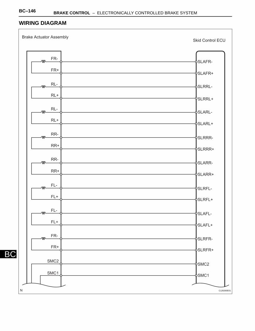
BC–146 BRAKE CONTROL – ELECTRONICALLY CONTROLLED BRAKE SYSTEM
BC
WIRING DIAGRAM
Brake Actuator AssemblySkid Control ECU
FR-
FR+
RL-
RL+
RL-
RL+
RR-
RR+
FL-
FL+
FL-
FL+
FR-
SMC2
SMC1
RR-
RR+
FR+
SLAFR-
SLAFR+
SLRRL-
SLRRL+
SLARL-
SLARL+
SLRRR-
SLRRR+
SLARR-
SLARR+
SLRFL-
SLRFL+
SLAFL+
SLAFL-
SLRFR+
SLRFR-
SMC2
SMC1
C126260E01
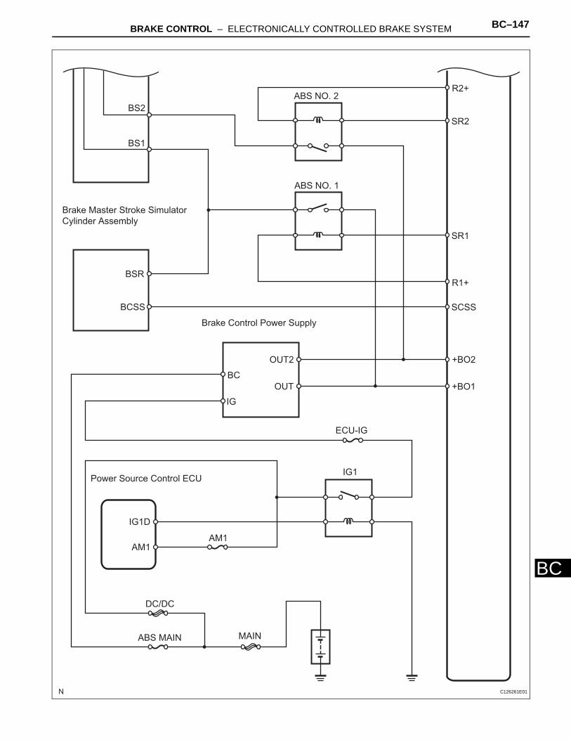
BRAKE CONTROL – ELECTRONICALLY CONTROLLED BRAKE SYSTEM BC–147
BC
BS2
BS1
Brake Master Stroke Simulator
Cylinder Assembly
BSR
BCSS
Brake Control Power Supply
BC
IG
OUT2
OUT
ABS NO. 2
ABS NO. 1
R2+
SR2
SR1
R1+
SCSS
+BO2
+BO1
ECU-IG
IG1Power Source Control ECU
IG1D
AM1AM1
MAIN
DC/DC
ABS MAIN
C126261E01
BC–148 BRAKE CONTROL – ELECTRONICALLY CONTROLLED BRAKE SYSTEM
BC
INSPECTION PROCEDURENOTICE:When replacing the skid control ECU, perform initialization of linear solenoid valve and calibration (see page BC-19).HINT:When C1364/61 is output together with C1341/62, C1342/63, C1343/64 and C1344/65, inspect and repair the trouble areas indicated by C1364/61 first.
(a) Check that there is no fluid leakage in the brake line between the brake actuator and the wheel cylinder which is the cause of DTCs.
(b) Check that the brake is not dragging.OK:
There is no fluid leakage or dragging.
NG
OK
(a) Bleed the air out of the front and rear systems (see page BR-3).
NEXT
(a) Clear the DTCs (see page BC-38). (b) Turn the power switch ON (READY). (c) Check the same DTCs are recorded (see page BC-38).
Result
HINT:DTC may be stored if foreign matter or air enters the solenoid valve.
B
A
1 CHECK BRAKE FLUID LEAKAGE
REPAIR OR REPLACE APPLICABLE PART
2 PERFORM AIR BLEED
3 RECONFIRM DTC
Result Proceed to
DTC is output A
DTC is not output B
END
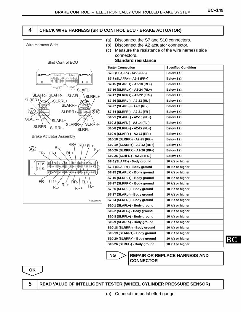
BRAKE CONTROL – ELECTRONICALLY CONTROLLED BRAKE SYSTEM BC–149
BC
(a) Disconnect the S7 and S10 connectors.(b) Disconnect the A2 actuator connector.(c) Measure the resistance of the wire harness side
connectors.Standard resistance
NG
OK
(a) Connect the pedal effort gauge.
4 CHECK WIRE HARNESS (SKID CONTROL ECU - BRAKE ACTUATOR)
SLAFR-SLAFR+
SLARL+
SLRRL+SLRFR+
SLRRL-
SLALR-
SLRFR-
SLAFL+
SLAFL- SLRFL+
SLARR-
SLRRR-SLARR+
SLRRR+
SLRFL-
FR-
RR+
RR-
RR+
FL+
FL-FL+
FR-
RL+FR+
FR+
RL-RL+
RL-
RR+FL-
Wire Harness Side
Skid Control ECU
S7 S10
Brake Actuator Assembly
A2
C132866E01
Tester Connection Specified Condition
S7-6 (SLAFR-) - A2-5 (FR-) Below 1 Ω
S7-7 (SLAFR+) - A2-8 (FR+) Below 1 Ω
S7-15 (SLARL+) - A2-10 (RL+) Below 1 Ω
S7-16 (SLRRL+) - A2-24 (RL+) Below 1 Ω
S7-17 (SLRFR+) - A2-22 (FR+) Below 1 Ω
S7-26 (SLRRL-) - A2-23 (RL-) Below 1 Ω
S7-27 (SLARL-) - A2-9 (RL-) Below 1 Ω
S7-34 (SLRFR-) - A2-21 (FR-) Below 1 Ω
S10-1 (SLAFL+) - A2-13 (FL+) Below 1 Ω
S10-2 (SLAFL-) - A2-14 (FL-) Below 1 Ω
S10-8 (SLRFL+) - A2-27 (FL+) Below 1 Ω
S10-9 (SLARR-) - A2-11 (RR-) Below 1 Ω
S10-18 (SLRRR-) - A2-25 (RR-) Below 1 Ω
S10-19 (SLARR+) - A2-12 (RR+) Below 1 Ω
S10-20 (SLRRR+) - A2-26 (RR+) Below 1 Ω
S10-26 (SLRFL-) - A2-28 (FL-) Below 1 Ω
S7-6 (SLAFR-) - Body ground 10 kΩ or higher
S7-7 (SLAFR+) - Body ground 10 kΩ or higher
S7-15 (SLARL+) - Body ground 10 kΩ or higher
S7-16 (SLRRL+) - Body ground 10 kΩ or higher
S7-17 (SLRFR+) - Body ground 10 kΩ or higher
S7-26 (SLRRL-) - Body ground 10 kΩ or higher
S7-27 (SLARL-) - Body ground 10 kΩ or higher
S7-34 (SLRFR-) - Body ground 10 kΩ or higher
S10-1 (SLAFL+) - Body ground 10 kΩ or higher
S10-2 (SLAFL-) - Body ground 10 kΩ or higher
S10-8 (SLRFL+) - Body ground 10 kΩ or higher
S10-9 (SLARR-) - Body ground 10 kΩ or higher
S10-18 (SLRRR-) - Body ground 10 kΩ or higher
S10-19 (SLARR+) - Body ground 10 kΩ or higher
S10-20 (SLRRR+) - Body ground 10 kΩ or higher
S10-26 (SLRFL-) - Body ground 10 kΩ or higher
REPAIR OR REPLACE HARNESS AND CONNECTOR
5 READ VALUE OF INTELLIGENT TESTER (WHEEL CYLINDER PRESSURE SENSOR)
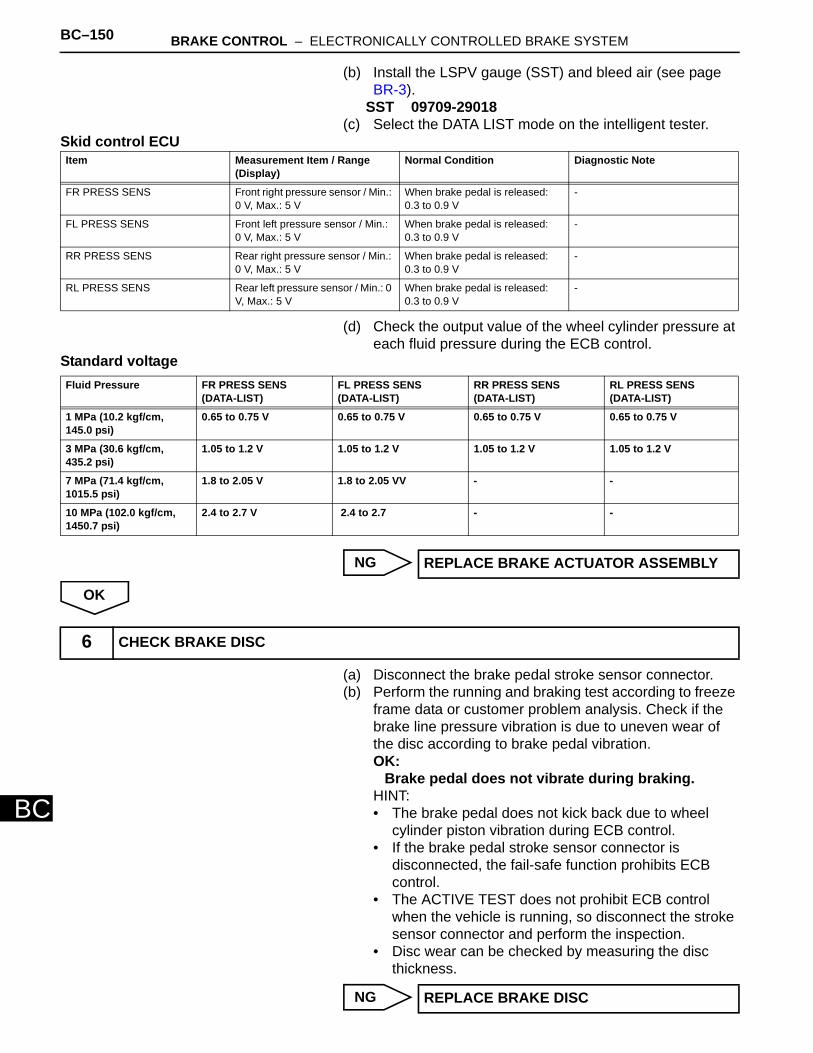
BC–150 BRAKE CONTROL – ELECTRONICALLY CONTROLLED BRAKE SYSTEM
BC
(b) Install the LSPV gauge (SST) and bleed air (see page BR-3).
SST 09709-29018(c) Select the DATA LIST mode on the intelligent tester.
Skid control ECU
(d) Check the output value of the wheel cylinder pressure at each fluid pressure during the ECB control.
Standard voltage
NG
OK
(a) Disconnect the brake pedal stroke sensor connector. (b) Perform the running and braking test according to freeze
frame data or customer problem analysis. Check if the brake line pressure vibration is due to uneven wear of the disc according to brake pedal vibration.OK:
Brake pedal does not vibrate during braking.HINT:• The brake pedal does not kick back due to wheel
cylinder piston vibration during ECB control. • If the brake pedal stroke sensor connector is
disconnected, the fail-safe function prohibits ECB control.
• The ACTIVE TEST does not prohibit ECB control when the vehicle is running, so disconnect the stroke sensor connector and perform the inspection.
• Disc wear can be checked by measuring the disc thickness.
NG
Item Measurement Item / Range (Display)
Normal Condition Diagnostic Note
FR PRESS SENS Front right pressure sensor / Min.: 0 V, Max.: 5 V
When brake pedal is released: 0.3 to 0.9 V
-
FL PRESS SENS Front left pressure sensor / Min.: 0 V, Max.: 5 V
When brake pedal is released: 0.3 to 0.9 V
-
RR PRESS SENS Rear right pressure sensor / Min.: 0 V, Max.: 5 V
When brake pedal is released: 0.3 to 0.9 V
-
RL PRESS SENS Rear left pressure sensor / Min.: 0 V, Max.: 5 V
When brake pedal is released: 0.3 to 0.9 V
-
Fluid Pressure FR PRESS SENS (DATA-LIST)
FL PRESS SENS (DATA-LIST)
RR PRESS SENS (DATA-LIST)
RL PRESS SENS (DATA-LIST)
1 MPa (10.2 kgf/cm, 145.0 psi)
0.65 to 0.75 V 0.65 to 0.75 V 0.65 to 0.75 V 0.65 to 0.75 V
3 MPa (30.6 kgf/cm, 435.2 psi)
1.05 to 1.2 V 1.05 to 1.2 V 1.05 to 1.2 V 1.05 to 1.2 V
7 MPa (71.4 kgf/cm, 1015.5 psi)
1.8 to 2.05 V 1.8 to 2.05 VV - -
10 MPa (102.0 kgf/cm, 1450.7 psi)
2.4 to 2.7 V 2.4 to 2.7 - -
REPLACE BRAKE ACTUATOR ASSEMBLY
6 CHECK BRAKE DISC
REPLACE BRAKE DISC
BRAKE CONTROL – ELECTRONICALLY CONTROLLED BRAKE SYSTEM BC–151
BC
OK
REPLACE BRAKE ACTUATOR ASSEMBLY
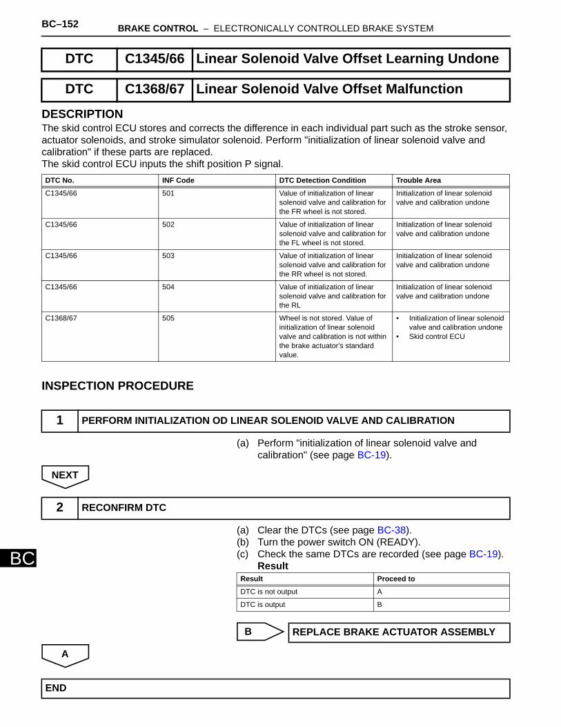
BC–152 BRAKE CONTROL – ELECTRONICALLY CONTROLLED BRAKE SYSTEM
BC
DESCRIPTIONThe skid control ECU stores and corrects the difference in each individual part such as the stroke sensor, actuator solenoids, and stroke simulator solenoid. Perform "initialization of linear solenoid valve and calibration" if these parts are replaced. The skid control ECU inputs the shift position P signal.
INSPECTION PROCEDURE
(a) Perform "initialization of linear solenoid valve and calibration" (see page BC-19).
NEXT
(a) Clear the DTCs (see page BC-38). (b) Turn the power switch ON (READY). (c) Check the same DTCs are recorded (see page BC-19).
Result
B
A
DTC C1345/66 Linear Solenoid Valve Offset Learning Undone
DTC C1368/67 Linear Solenoid Valve Offset Malfunction
DTC No. INF Code DTC Detection Condition Trouble Area
C1345/66 501 Value of initialization of linear solenoid valve and calibration for the FR wheel is not stored.
Initialization of linear solenoid valve and calibration undone
C1345/66 502 Value of initialization of linear solenoid valve and calibration for the FL wheel is not stored.
Initialization of linear solenoid valve and calibration undone
C1345/66 503 Value of initialization of linear solenoid valve and calibration for the RR wheel is not stored.
Initialization of linear solenoid valve and calibration undone
C1345/66 504 Value of initialization of linear solenoid valve and calibration for the RL
Initialization of linear solenoid valve and calibration undone
C1368/67 505 Wheel is not stored. Value of initialization of linear solenoid valve and calibration is not within the brake actuator's standard value.
• Initialization of linear solenoid valve and calibration undone
• Skid control ECU
1 PERFORM INITIALIZATION OD LINEAR SOLENOID VALVE AND CALIBRATION
2 RECONFIRM DTC
Result Proceed to
DTC is not output A
DTC is output B
REPLACE BRAKE ACTUATOR ASSEMBLY
END
BRAKE CONTROL – ELECTRONICALLY CONTROLLED BRAKE SYSTEM BC–153
BC
DESCRIPTIONThe accumulator (ACC) pressure sensor is built into the brake actuator. The skid control ECU detects the accumulator pressure from the data sent from the accumulator pressure sensor, and then runs and stops the pump motor by operating the motor relay. DTCs may be output if the accumulator pressure drops due to frequent braking (this is not a malfunction).
DTC C1365/54 Accumulator Pressure Sensor Malfunction
DTC No. INF Code DTC Detection Condition Trouble Area
C1365/54 211 Sensor power 1 (VCM1) voltage is 4.7 V or less or 5.3 V or more for at least 0.05 sec.
• Brake actuator assembly (accumulator pressure sensor)
• Skid control ECU
C1365/54 212 Ratio of accumulator pressure sensor output voltage (PACC) to sensor power 1 (VCM1) voltage is 5% or less or 90.5% or more for at least 0.05 sec.
• Brake actuator assembly (accumulator pressure sensor)
• Skid control ECU
C1365/54 214 Total wheel cylinder pressure sensor exceeds 12 MPa after depressing brake pedal, but accumulator pressure sensor output voltage (PACC) changes less than 0.5 MPa for at least 0.5 sec.
• Brake actuator assembly (accumulator pressure sensor)
• Skid control ECU
C1365/54 215 Ratio of accumulator pressure sensor output voltage (PACC) to sensor power 1 (VCM1) voltage is 90.5% or less for at least 0.1 sec. during self-diagnosis.
• Brake actuator assembly (accumulator pressure sensor)
• Skid control ECU
C1365/54 216 Voltage difference is 0.3 V or more before and after changing the pull up resistance in sensor signal input circuit (loose contact).
• Brake actuator assembly (accumulator pressure sensor)
• Skid control ECU

BC–154 BRAKE CONTROL – ELECTRONICALLY CONTROLLED BRAKE SYSTEM
BC
WIRING DIAGRAM
INSPECTION PROCEDURENOTICE:When replacing the skid control ECU, perform initialization of linear solenoid valve and calibration (see page BC-19).
Brake Actuator Skid Control ECU
PRL PRL
PFR PFR
PMC1 PMC1
PCK1 PCK1
E1 E
VCM1 VCM1
E2 E2
PRR PRR
PFL PFL
PMC2 PMC2
VCM2 VCM2
PCK2 PCK2
PACC PACC
C126252E01
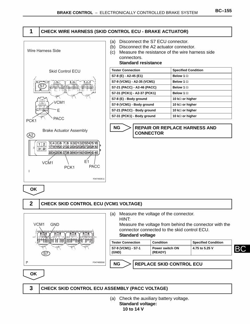
BRAKE CONTROL – ELECTRONICALLY CONTROLLED BRAKE SYSTEM BC–155
BC
(a) Disconnect the S7 ECU connector.(b) Disconnect the A2 actuator connector.(c) Measure the resistance of the wire harness side
connectors.Standard resistance
NG
OK
(a) Measure the voltage of the connector.HINT:Measure the voltage from behind the connector with the connector connected to the skid control ECU.Standard voltage
NG
OK
(a) Check the auxiliary battery voltage. Standard voltage:
10 to 14 V
1 CHECK WIRE HARNESS (SKID CONTROL ECU - BRAKE ACTUATOR)
Wire Harness Side
Skid Control ECU
VCM1
PACCPCK1
E
Brake Actuator Assembly
A2
VCM1PACCPCK1
E1
S7
F047492E11
Tester Connection Specified Condition
S7-8 (E) - A2-45 (E1) Below 1 Ω
S7-9 (VCM1) - A2-35 (VCM1) Below 1 Ω
S7-21 (PACC) - A2-46 (PACC) Below 1 Ω
S7-31 (PCK1) - A2-37 (PCK1) Below 1 Ω
S7-8 (E) - Body ground 10 kΩ or higher
S7-9 (VCM1) - Body ground 10 kΩ or higher
S7-21 (PACC) - Body ground 10 kΩ or higher
S7-31 (PCK1) - Body ground 10 kΩ or higher
REPAIR OR REPLACE HARNESS AND CONNECTOR
2 CHECK SKID CONTROL ECU (VCM1 VOLTAGE)
VCM1 GND
S7
F047485E66
Tester Connection Condition Specified Condition
S7-9 (VCM1) - S7-1 (GND)
Power switch ON (READY)
4.75 to 5.25 V
REPLACE SKID CONTROL ECU
3 CHECK SKID CONTROL ECU ASSEMBLY (PACC VOLTAGE)
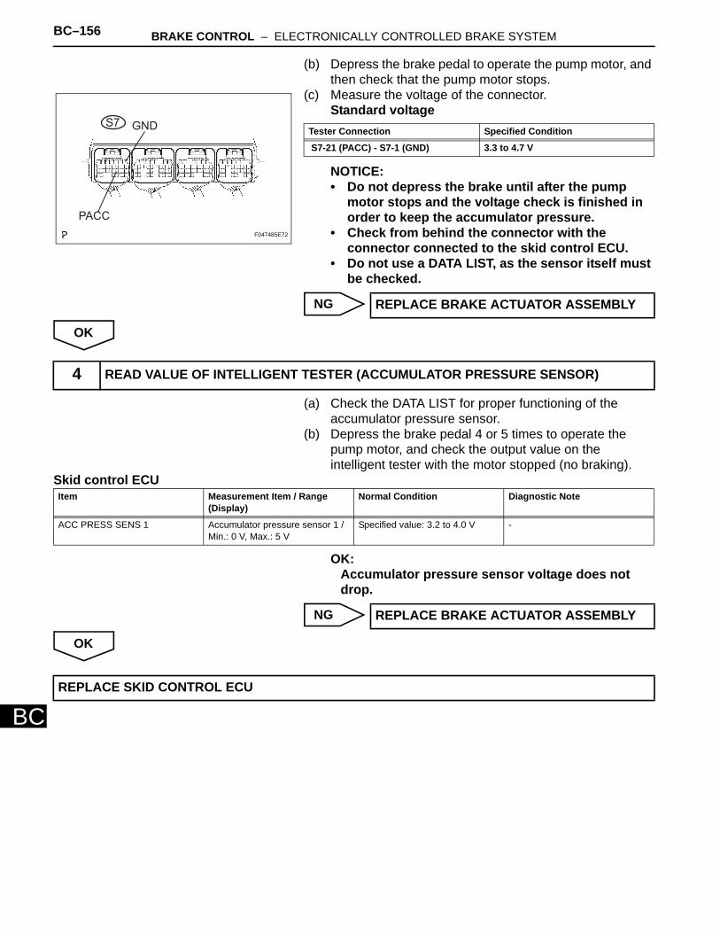
BC–156 BRAKE CONTROL – ELECTRONICALLY CONTROLLED BRAKE SYSTEM
BC
(b) Depress the brake pedal to operate the pump motor, and then check that the pump motor stops.
(c) Measure the voltage of the connector.Standard voltage
NOTICE:• Do not depress the brake until after the pump
motor stops and the voltage check is finished in order to keep the accumulator pressure.
• Check from behind the connector with the connector connected to the skid control ECU.
• Do not use a DATA LIST, as the sensor itself must be checked.
NG
OK
(a) Check the DATA LIST for proper functioning of the accumulator pressure sensor.
(b) Depress the brake pedal 4 or 5 times to operate the pump motor, and check the output value on the intelligent tester with the motor stopped (no braking).
Skid control ECU
OK:Accumulator pressure sensor voltage does not drop.
NG
OK
PACC
GNDS7
F047485E72
Tester Connection Specified Condition
S7-21 (PACC) - S7-1 (GND) 3.3 to 4.7 V
REPLACE BRAKE ACTUATOR ASSEMBLY
4 READ VALUE OF INTELLIGENT TESTER (ACCUMULATOR PRESSURE SENSOR)
Item Measurement Item / Range (Display)
Normal Condition Diagnostic Note
ACC PRESS SENS 1 Accumulator pressure sensor 1 / Min.: 0 V, Max.: 5 V
Specified value: 3.2 to 4.0 V -
REPLACE BRAKE ACTUATOR ASSEMBLY
REPLACE SKID CONTROL ECU
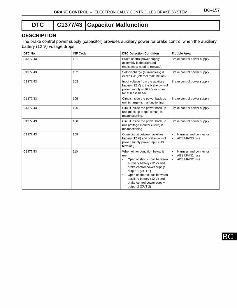
BRAKE CONTROL – ELECTRONICALLY CONTROLLED BRAKE SYSTEM BC–157
BC
DESCRIPTIONThe brake control power supply (capacitor) provides auxiliary power for brake control when the auxiliary battery (12 V) voltage drops.
DTC C1377/43 Capacitor Malfunction
DTC No. INF Code DTC Detection Condition Trouble Area
C1377/43 101 Brake control power supply assembly is deteriorated (indicates a need to replace).
Brake control power supply
C1377/43 102 Self-discharge (current leak) is excessive (internal malfunction).
Brake control power supply
C1377/43 103 Input voltage from the auxiliary battery (12 V) to the brake control power supply is 16.4 V or more for at least 10 sec.
Brake control power supply
C1377/43 105 Circuit inside the power back up unit (charge) is malfunctioning.
Brake control power supply
C1377/43 106 Circuit inside the power back up unit (back up output circuit) is malfunctioning.
Brake control power supply
C1377/43 108 Circuit inside the power back up unit (voltage monitor circuit) is malfunctioning.
Brake control power supply
C1377/43 109 Open circuit between auxiliary battery (12 V) and brake control power supply power input (+BC terminal).
• Harness and connector • ABS MAIN3 fuse
C1377/43 110 When either condition below is met:• Open or short circuit between
auxiliary battery (12 V) and brake control power supply output 1 (OUT 1).
• Open or short circuit between auxiliary battery (12 V) and brake control power supply output 2 (OUT 2)
• Harness and connector • ABS MAIN1 fuse • ABS MAIN2 fuse
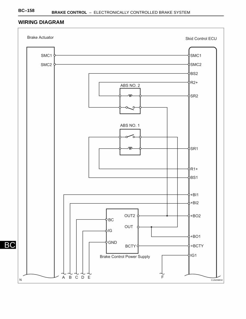
BC–158 BRAKE CONTROL – ELECTRONICALLY CONTROLLED BRAKE SYSTEM
BC
WIRING DIAGRAM
Brake Actuator
SMC1
SMC2
Skid Control ECU
SMC1
SMC2
BS2
R2+
SR2
SR1
R1+
BS1
+BI1
+BI2
+BO2
+BO1
IG1
ABS NO. 2
ABS NO. 1
Brake Control Power Supply
BC
IG
GND
OUT2
OUT
A B C D E F
BCTY +BCTY
C126258E02
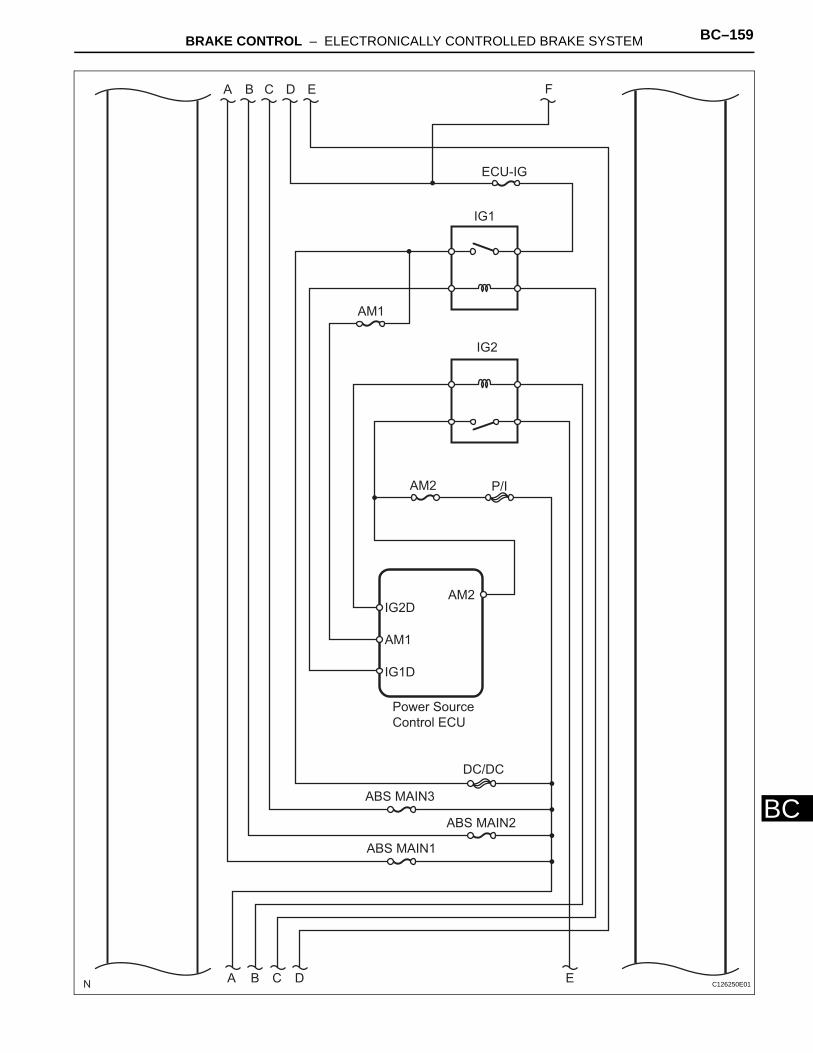
BRAKE CONTROL – ELECTRONICALLY CONTROLLED BRAKE SYSTEM BC–159
BC
A B C D E F
ECU-IG
IG1
AM1
IG2
Power Source
Control ECU
AM2IG2D
AM1
IG1D
AM2 P/I
DC/DC
ABS MAIN3
ABS MAIN2
ABS MAIN1
A B C D E C126250E01
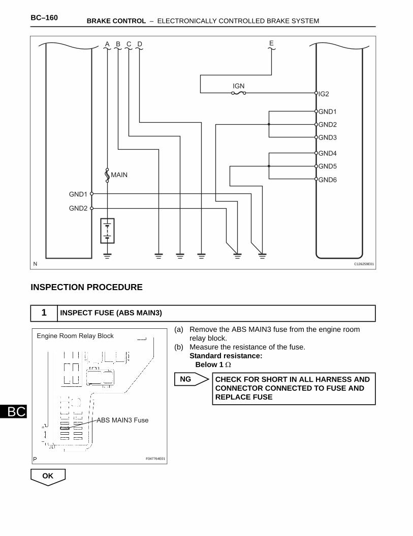
BC–160 BRAKE CONTROL – ELECTRONICALLY CONTROLLED BRAKE SYSTEM
BC
INSPECTION PROCEDURE
(a) Remove the ABS MAIN3 fuse from the engine room relay block.
(b) Measure the resistance of the fuse.Standard resistance:
Below 1 Ω
NG
OK
1 INSPECT FUSE (ABS MAIN3)
A B C D
MAIN
GND1
GND2
IGN
E
IG2
GND1
GND2
GND3
GND4
GND5
GND6
C126259E01
Engine Room Relay Block
ABS MAIN3 Fuse
F047764E01
CHECK FOR SHORT IN ALL HARNESS AND CONNECTOR CONNECTED TO FUSE AND REPLACE FUSE
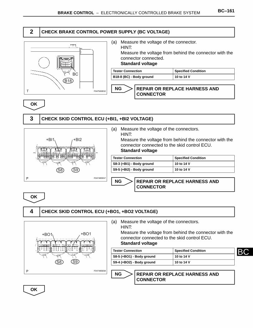
BRAKE CONTROL – ELECTRONICALLY CONTROLLED BRAKE SYSTEM BC–161
BC
(a) Measure the voltage of the connector.HINT:Measure the voltage from behind the connector with the connector connected.Standard voltage
NG
OK
(a) Measure the voltage of the connectors.HINT:Measure the voltage from behind the connector with the connector connected to the skid control ECU.Standard voltage
NG
OK
(a) Measure the voltage of the connectors.HINT:Measure the voltage from behind the connector with the connector connected to the skid control ECU.Standard voltage
NG
OK
2 CHECK BRAKE CONTROL POWER SUPPLY (BC VOLTAGE)
B18
BC
F047500E02
Tester Connection Specified Condition
B18-8 (BC) - Body ground 10 to 14 V
REPAIR OR REPLACE HARNESS AND CONNECTOR
3 CHECK SKID CONTROL ECU (+BI1, +BI2 VOLTAGE)
S8 S9
+BI1 +BI2
F047485E67
Tester Connection Specified Condition
S8-3 (+BI1) - Body ground 10 to 14 V
S9-5 (+BI2) - Body ground 10 to 14 V
REPAIR OR REPLACE HARNESS AND CONNECTOR
4 CHECK SKID CONTROL ECU (+BO1, +BO2 VOLTAGE)
S8 S9
+BO1 +BO1
F047485E68
Tester Connection Specified Condition
S8-5 (+BO1) - Body ground 10 to 14 V
S9-4 (+BO2) - Body ground 10 to 14 V
REPAIR OR REPLACE HARNESS AND CONNECTOR
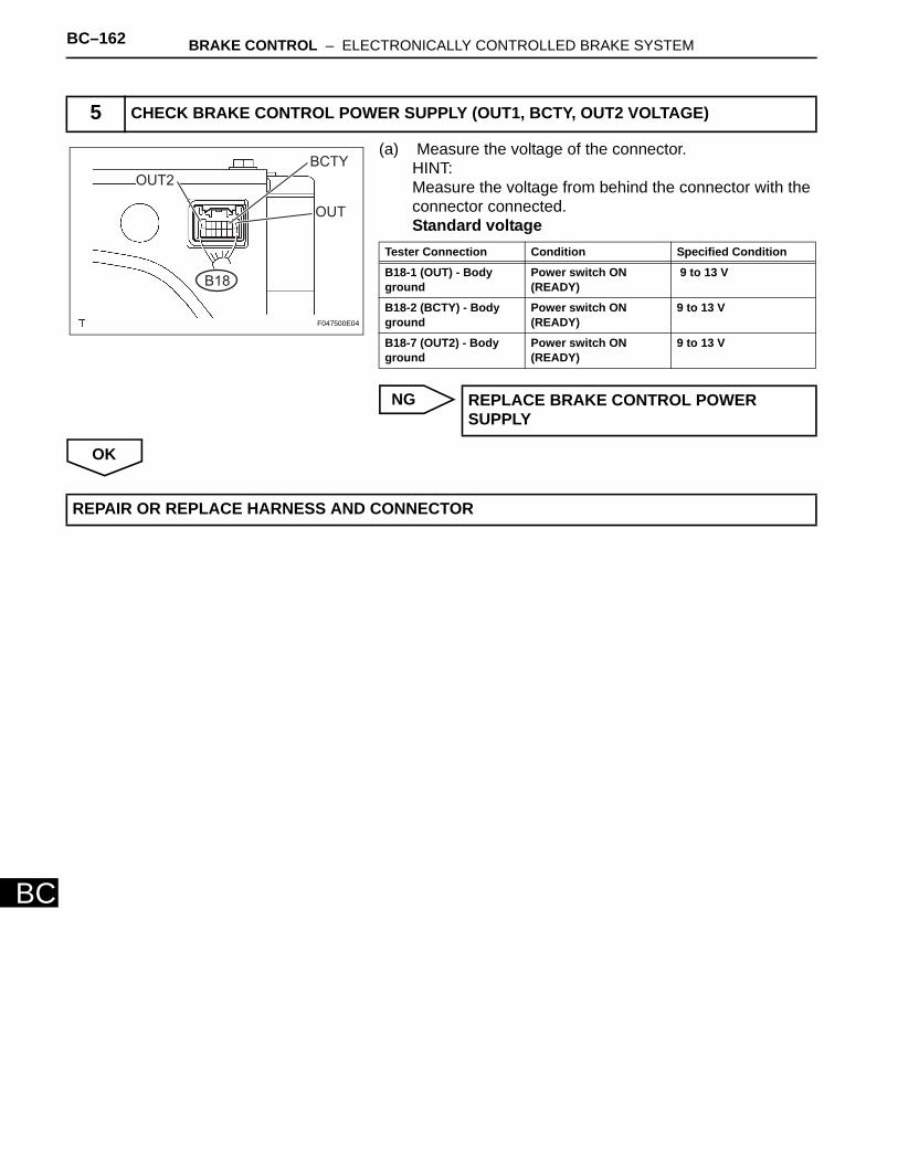
BC–162 BRAKE CONTROL – ELECTRONICALLY CONTROLLED BRAKE SYSTEM
BC
(a) Measure the voltage of the connector.HINT:Measure the voltage from behind the connector with the connector connected.Standard voltage
NG
OK
5 CHECK BRAKE CONTROL POWER SUPPLY (OUT1, BCTY, OUT2 VOLTAGE)
OUT2
BCTY
OUT
B18
F047500E04
Tester Connection Condition Specified Condition
B18-1 (OUT) - Body ground
Power switch ON (READY)
9 to 13 V
B18-2 (BCTY) - Body ground
Power switch ON (READY)
9 to 13 V
B18-7 (OUT2) - Body ground
Power switch ON (READY)
9 to 13 V
REPLACE BRAKE CONTROL POWER SUPPLY
REPAIR OR REPLACE HARNESS AND CONNECTOR
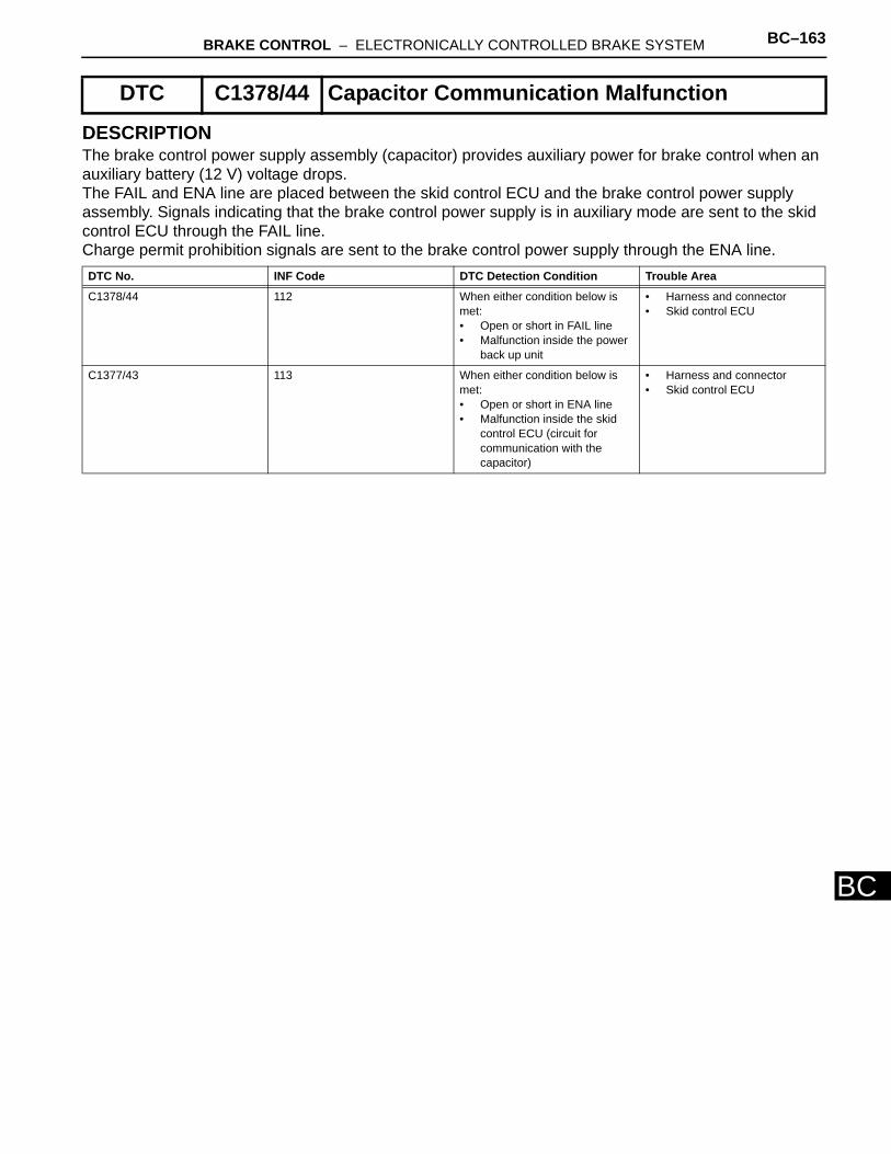
BRAKE CONTROL – ELECTRONICALLY CONTROLLED BRAKE SYSTEM BC–163
BC
DESCRIPTIONThe brake control power supply assembly (capacitor) provides auxiliary power for brake control when an auxiliary battery (12 V) voltage drops. The FAIL and ENA line are placed between the skid control ECU and the brake control power supply assembly. Signals indicating that the brake control power supply is in auxiliary mode are sent to the skid control ECU through the FAIL line. Charge permit prohibition signals are sent to the brake control power supply through the ENA line.
DTC C1378/44 Capacitor Communication Malfunction
DTC No. INF Code DTC Detection Condition Trouble Area
C1378/44 112 When either condition below is met:• Open or short in FAIL line• Malfunction inside the power
back up unit
• Harness and connector • Skid control ECU
C1377/43 113 When either condition below is met:• Open or short in ENA line • Malfunction inside the skid
control ECU (circuit for communication with the capacitor)
• Harness and connector • Skid control ECU
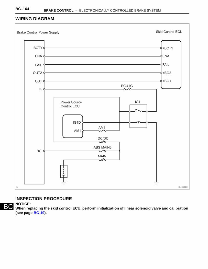
BC–164 BRAKE CONTROL – ELECTRONICALLY CONTROLLED BRAKE SYSTEM
BC
WIRING DIAGRAM
INSPECTION PROCEDURENOTICE:When replacing the skid control ECU, perform initialization of linear solenoid valve and calibration (see page BC-19).
Brake Control Power Supply Skid Control ECU
+BCTYBCTY
ENA
FAIL
+BO2
+BO1
ENA
FAIL
OUT2
OUT
IG
IG1Power Source
Control ECU
AM1
IG1D
AM1
DC/DC
ABS MAIN3
MAIN
BC
ECU-IG
C126263E01
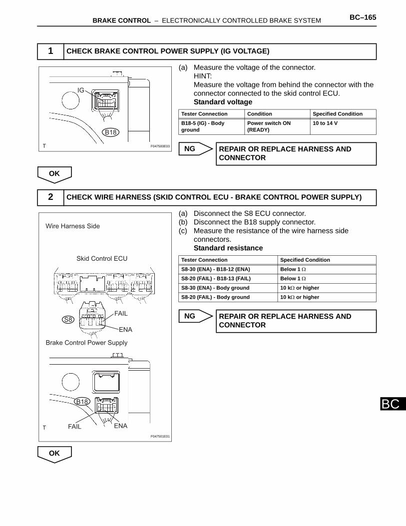
BRAKE CONTROL – ELECTRONICALLY CONTROLLED BRAKE SYSTEM BC–165
BC
(a) Measure the voltage of the connector.HINT:Measure the voltage from behind the connector with the connector connected to the skid control ECU.Standard voltage
NG
OK
(a) Disconnect the S8 ECU connector.(b) Disconnect the B18 supply connector.(c) Measure the resistance of the wire harness side
connectors.Standard resistance
NG
OK
1 CHECK BRAKE CONTROL POWER SUPPLY (IG VOLTAGE)
B18
IG
F047500E03
Tester Connection Condition Specified Condition
B18-5 (IG) - Body ground
Power switch ON (READY)
10 to 14 V
REPAIR OR REPLACE HARNESS AND CONNECTOR
2 CHECK WIRE HARNESS (SKID CONTROL ECU - BRAKE CONTROL POWER SUPPLY)
Wire Harness Side
Skid Control ECU
S8FAIL
ENA
Brake Control Power Supply
ENAFAIL
B18
F047501E01
Tester Connection Specified Condition
S8-30 (ENA) - B18-12 (ENA) Below 1 Ω
S8-20 (FAIL) - B18-13 (FAIL) Below 1 Ω
S8-30 (ENA) - Body ground 10 kΩ or higher
S8-20 (FAIL) - Body ground 10 kΩ or higher
REPAIR OR REPLACE HARNESS AND CONNECTOR
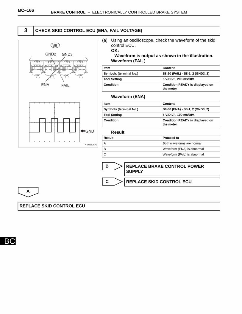
BC–166 BRAKE CONTROL – ELECTRONICALLY CONTROLLED BRAKE SYSTEM
BC
(a) Using an oscilloscope, check the waveform of the skid control ECU. OK:
Waveform is output as shown in the illustration.Waveform (FAIL)
Waveform (ENA)
Result
B
C
A
3 CHECK SKID CONTROL ECU (ENA, FAIL VOLTAGE)
S8
ENA FAIL
GND
GND3GND2
C133162E01
Item Content
Symbols (terminal No.) S8-20 (FAIL) - S8-1, 2 (GND3, 2)
Tool Setting 5 V/DIV/., 200 ms/DIV.
Condition Condition READY is displayed on the meter
Item Content
Symbols (terminal No.) S8-30 (ENA) - S8-1, 2 (GND3, 2)
Tool Setting 5 V/DIV/., 100 ms/DIV.
Condition Condition READY is displayed on the meter
Result Proceed to
A Both waveforms are normal
B Waveform (ENA) is abnormal
C Waveform (FAIL) is abnormal
REPLACE BRAKE CONTROL POWER SUPPLY
REPLACE SKID CONTROL ECU
REPLACE SKID CONTROL ECU
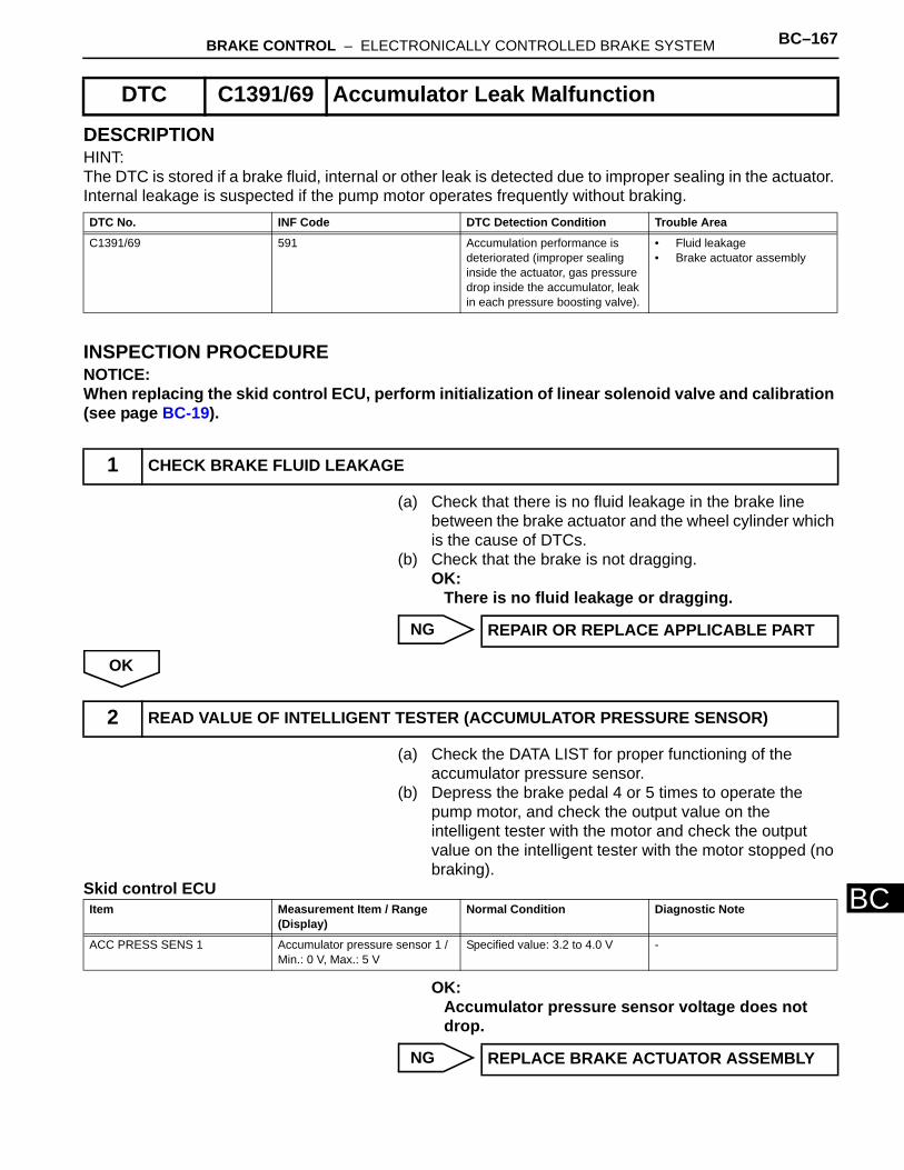
BRAKE CONTROL – ELECTRONICALLY CONTROLLED BRAKE SYSTEM BC–167
BC
DESCRIPTIONHINT:The DTC is stored if a brake fluid, internal or other leak is detected due to improper sealing in the actuator. Internal leakage is suspected if the pump motor operates frequently without braking.
INSPECTION PROCEDURENOTICE:When replacing the skid control ECU, perform initialization of linear solenoid valve and calibration (see page BC-19).
(a) Check that there is no fluid leakage in the brake line between the brake actuator and the wheel cylinder which is the cause of DTCs.
(b) Check that the brake is not dragging.OK:
There is no fluid leakage or dragging.
NG
OK
(a) Check the DATA LIST for proper functioning of the accumulator pressure sensor.
(b) Depress the brake pedal 4 or 5 times to operate the pump motor, and check the output value on the intelligent tester with the motor and check the output value on the intelligent tester with the motor stopped (no braking).
Skid control ECU
OK:Accumulator pressure sensor voltage does not drop.
NG
DTC C1391/69 Accumulator Leak Malfunction
DTC No. INF Code DTC Detection Condition Trouble Area
C1391/69 591 Accumulation performance is deteriorated (improper sealing inside the actuator, gas pressure drop inside the accumulator, leak in each pressure boosting valve).
• Fluid leakage • Brake actuator assembly
1 CHECK BRAKE FLUID LEAKAGE
REPAIR OR REPLACE APPLICABLE PART
2 READ VALUE OF INTELLIGENT TESTER (ACCUMULATOR PRESSURE SENSOR)
Item Measurement Item / Range (Display)
Normal Condition Diagnostic Note
ACC PRESS SENS 1 Accumulator pressure sensor 1 / Min.: 0 V, Max.: 5 V
Specified value: 3.2 to 4.0 V -
REPLACE BRAKE ACTUATOR ASSEMBLY
BC–168 BRAKE CONTROL – ELECTRONICALLY CONTROLLED BRAKE SYSTEM
BC
OK
REPLACE SKID CONTROL ECU
BRAKE CONTROL – ELECTRONICALLY CONTROLLED BRAKE SYSTEM BC–169
BC
DESCRIPTIONThe ABS warning light illuminates to inform the driver that there is a problem in the ABS.When DTC output is normal and the ABS warning light remains on, perform troubleshooting as indicated below.
ABS Warning Light Remains ON
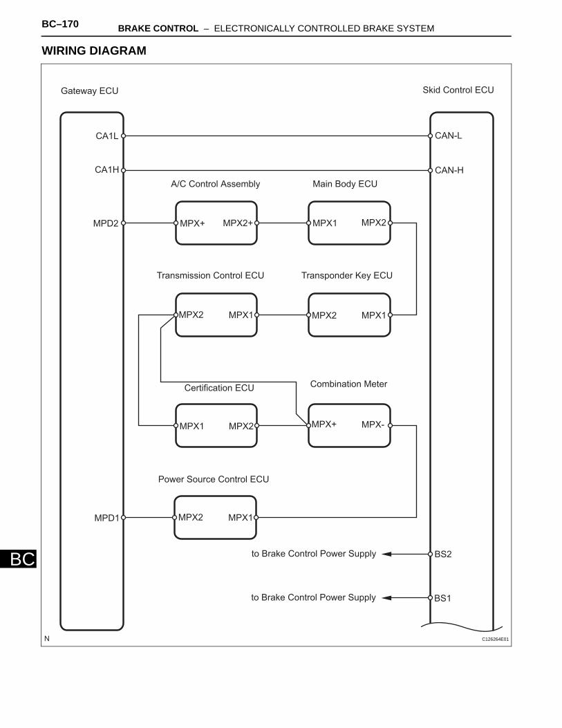
BC–170 BRAKE CONTROL – ELECTRONICALLY CONTROLLED BRAKE SYSTEM
BC
WIRING DIAGRAM
Gateway ECU Skid Control ECU
CAN-L
CAN-H
CA1L
CA1H
MPD2
A/C Control Assembly Main Body ECU
MPX+ MPX2+ MPX1 MPX2
Transponder Key ECUTransmission Control ECU
MPX2 MPX1 MPX2 MPX1
Combination MeterCertification ECU
MPX2MPX1 MPX+ MPX-
Power Source Control ECU
MPX2 MPX1MPD1
BS2
BS1
to Brake Control Power Supply
to Brake Control Power Supply
C126264E01
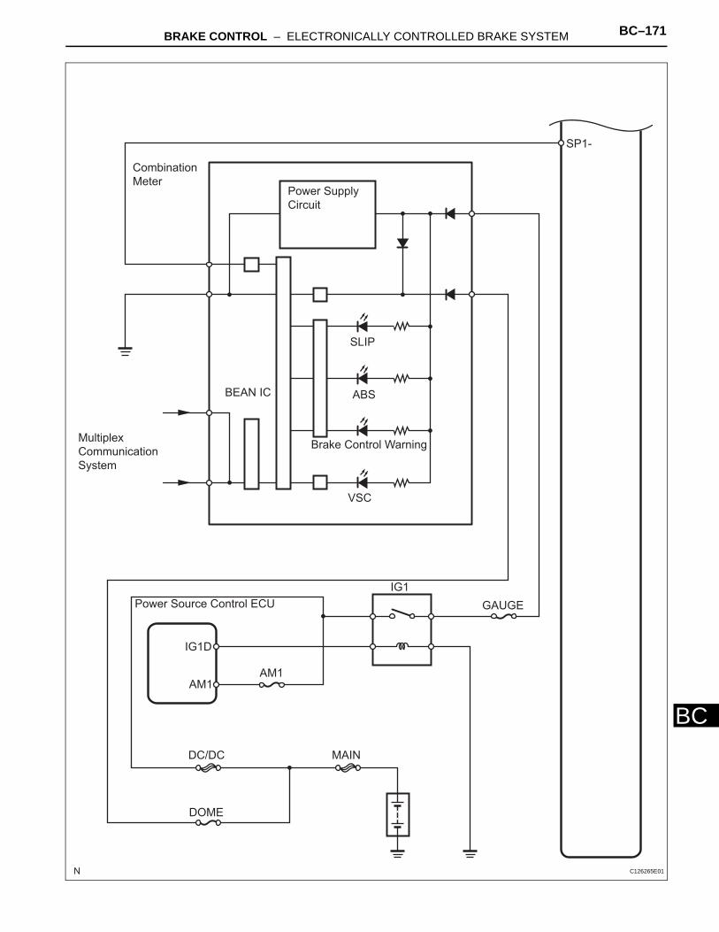
BRAKE CONTROL – ELECTRONICALLY CONTROLLED BRAKE SYSTEM BC–171
BC
Combination
Meter
SP1-
Power Supply
Circuit
SLIP
ABS
Brake Control Warning
VSC
BEAN IC
Multiplex
Communication
System
Power Source Control ECU
IG1D
IG1
AM1AM1
GAUGE
MAINDC/DC
DOME
C126265E01
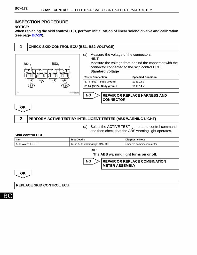
BC–172 BRAKE CONTROL – ELECTRONICALLY CONTROLLED BRAKE SYSTEM
BC
INSPECTION PROCEDURENOTICE:When replacing the skid control ECU, perform initialization of linear solenoid valve and calibration (see page BC-19).
(a) Measure the voltage of the connectors.HINT:Measure the voltage from behind the connector with the connector connected to the skid control ECU.Standard voltage
NG
OK
(a) Select the ACTIVE TEST, generate a control command, and then check that the ABS warning light operates.
Skid control ECU
OK:The ABS warning light turns on or off.
NG
OK
1 CHECK SKID CONTROL ECU (BS1, BS2 VOLTAGE)
BS1 BS2
S7 S10
F047485E70
Tester Connection Specified Condition
S7-3 (BS1) - Body ground 10 to 14 V
S10-7 (BS2) - Body ground 10 to 14 V
REPAIR OR REPLACE HARNESS AND CONNECTOR
2 PERFORM ACTIVE TEST BY INTELLIGENT TESTER (ABS WARNING LIGHT)
Item Test Details Diagnostic Note
ABS WARN LIGHT Turns ABS warning light ON / OFF Observe combination meter
REPAIR OR REPLACE COMBINATION METER ASSEMBLY
REPLACE SKID CONTROL ECU

BRAKE CONTROL – ELECTRONICALLY CONTROLLED BRAKE SYSTEM BC–173
BC
INSPECTION PROCEDURE
(a) Check if a CAN communication system DTC is output (see page CA-16). Result
B
A
(a) Check if a multiplex communication system DTC is output (see page MP-7).Result
B
A
ABS Warning Light does not Come ON
1 CHECK CAN COMMUNICATION SYSTEM
Result Proceed to
DTC is not output A
DTC is output B
REPAIR CAN COMMUNICATION SYSTEM
2 CHECK MULTIPLEX COMMUNICATION SYSTEM
Result Proceed to
DTC is not output A
DTC is output B
REPAIR MULTIPLEX COMMUNICATION SYSTEM
REPAIR OR REPLACE COMBINATION METER ASSEMBLY
BC–174 BRAKE CONTROL – ELECTRONICALLY CONTROLLED BRAKE SYSTEM
BC
DESCRIPTIONThe VSC warning light illuminates to inform the driver that there is a problem in the Enhanced VSC. When DTC output is normal and the VSC warning light remains on, perform troubleshooting as indicated below.
VSC Warning Light Remains ON
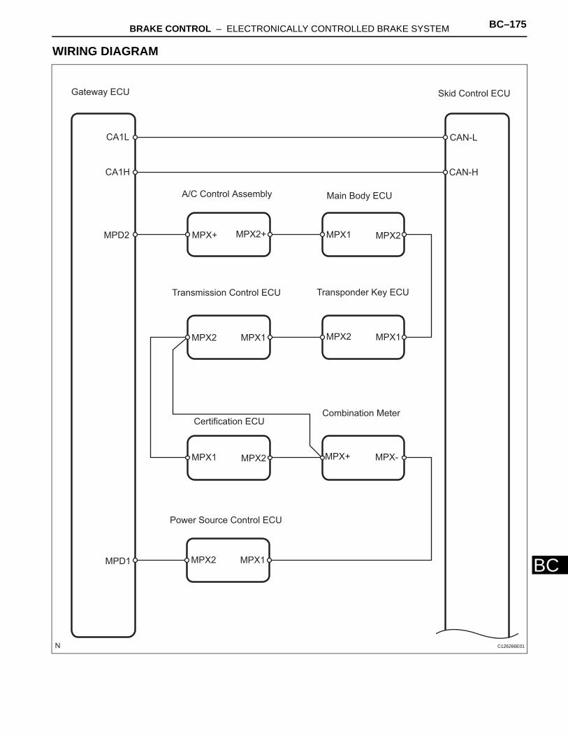
BRAKE CONTROL – ELECTRONICALLY CONTROLLED BRAKE SYSTEM BC–175
BC
WIRING DIAGRAM
Gateway ECU Skid Control ECU
CAN-L
CAN-H
CA1L
CA1H
MPD2
A/C Control Assembly Main Body ECU
MPX1 MPX2MPX+ MPX2+
Transmission Control ECU Transponder Key ECU
MPX1MPX2MPX1MPX2
Certification ECUCombination Meter
MPX1 MPX2 MPX+ MPX-
Power Source Control ECU
MPX1MPX2MPD1
C126266E01
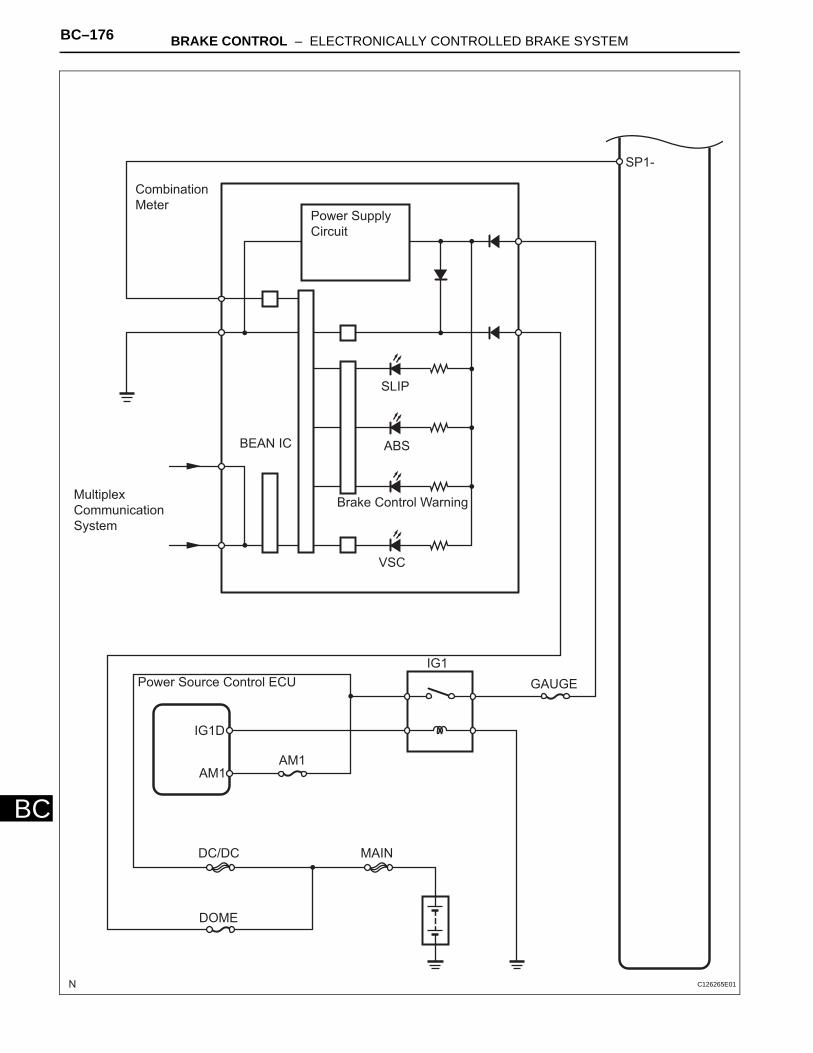
BC–176 BRAKE CONTROL – ELECTRONICALLY CONTROLLED BRAKE SYSTEM
BC
Combination
Meter
SP1-
Power Supply
Circuit
SLIP
ABS
Brake Control Warning
VSC
BEAN IC
Multiplex
Communication
System
Power Source Control ECU
IG1D
IG1
AM1AM1
GAUGE
MAINDC/DC
DOME
C126265E01
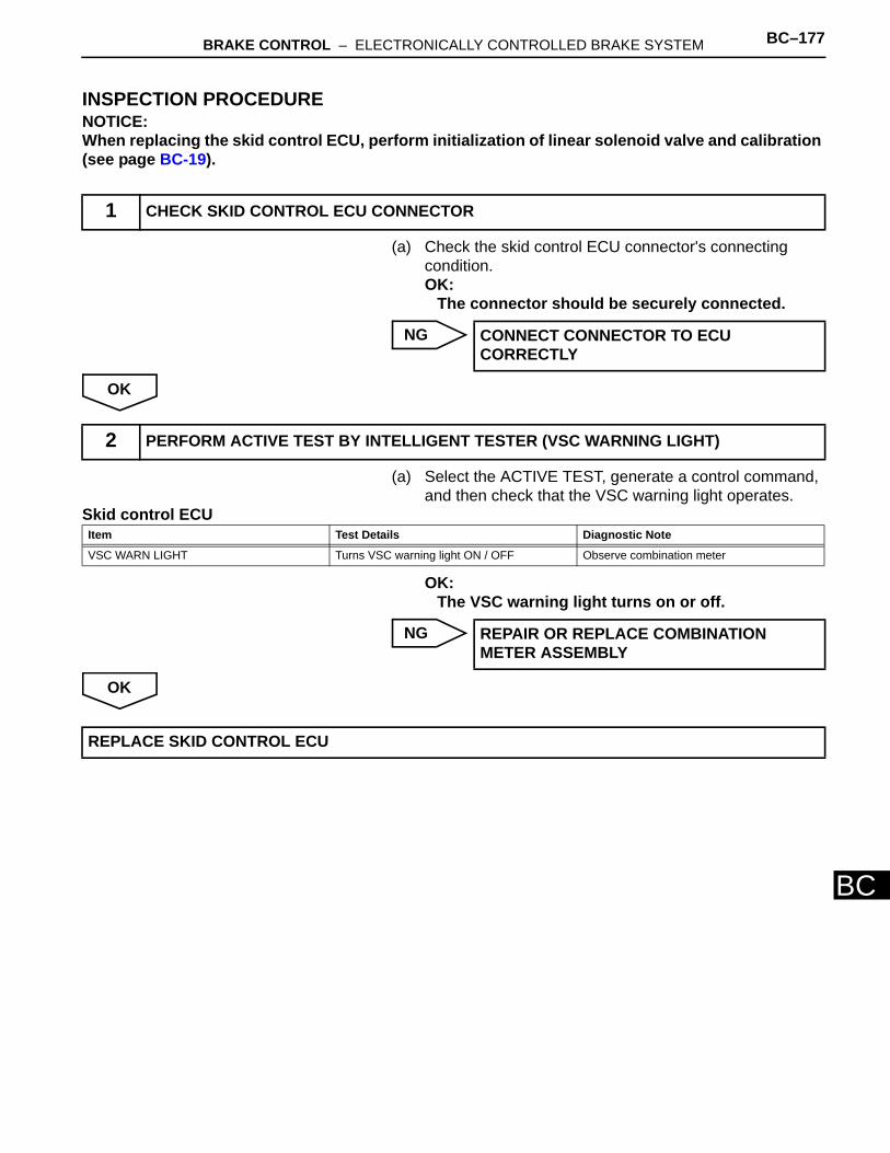
BRAKE CONTROL – ELECTRONICALLY CONTROLLED BRAKE SYSTEM BC–177
BC
INSPECTION PROCEDURENOTICE:When replacing the skid control ECU, perform initialization of linear solenoid valve and calibration (see page BC-19).
(a) Check the skid control ECU connector's connecting condition.OK:
The connector should be securely connected.
NG
OK
(a) Select the ACTIVE TEST, generate a control command, and then check that the VSC warning light operates.
Skid control ECU
OK:The VSC warning light turns on or off.
NG
OK
1 CHECK SKID CONTROL ECU CONNECTOR
CONNECT CONNECTOR TO ECU CORRECTLY
2 PERFORM ACTIVE TEST BY INTELLIGENT TESTER (VSC WARNING LIGHT)
Item Test Details Diagnostic Note
VSC WARN LIGHT Turns VSC warning light ON / OFF Observe combination meter
REPAIR OR REPLACE COMBINATION METER ASSEMBLY
REPLACE SKID CONTROL ECU
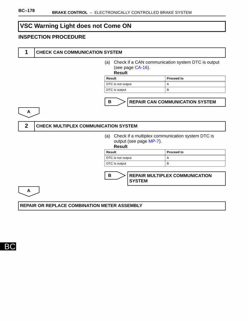
BC–178 BRAKE CONTROL – ELECTRONICALLY CONTROLLED BRAKE SYSTEM
BC
INSPECTION PROCEDURE
(a) Check if a CAN communication system DTC is output (see page CA-16).Result
B
A
(a) Check if a multiplex communication system DTC is output (see page MP-7).Result
B
A
VSC Warning Light does not Come ON
1 CHECK CAN COMMUNICATION SYSTEM
Result Proceed to
DTC is not output A
DTC is output B
REPAIR CAN COMMUNICATION SYSTEM
2 CHECK MULTIPLEX COMMUNICATION SYSTEM
Result Proceed to
DTC is not output A
DTC is output B
REPAIR MULTIPLEX COMMUNICATION SYSTEM
REPAIR OR REPLACE COMBINATION METER ASSEMBLY
BRAKE CONTROL – ELECTRONICALLY CONTROLLED BRAKE SYSTEM BC–179
BC
DESCRIPTIONThe BRAKE warning light comes on when the brake fluid is insufficient or the parking brake is applied. The skid control ECU is connected to the combination meter via the CAN and multiplex communications. When the DTC is normal and BRAKE warning light remains on, perform troubleshooting as indicated below.
Brake Warning Light Circuit
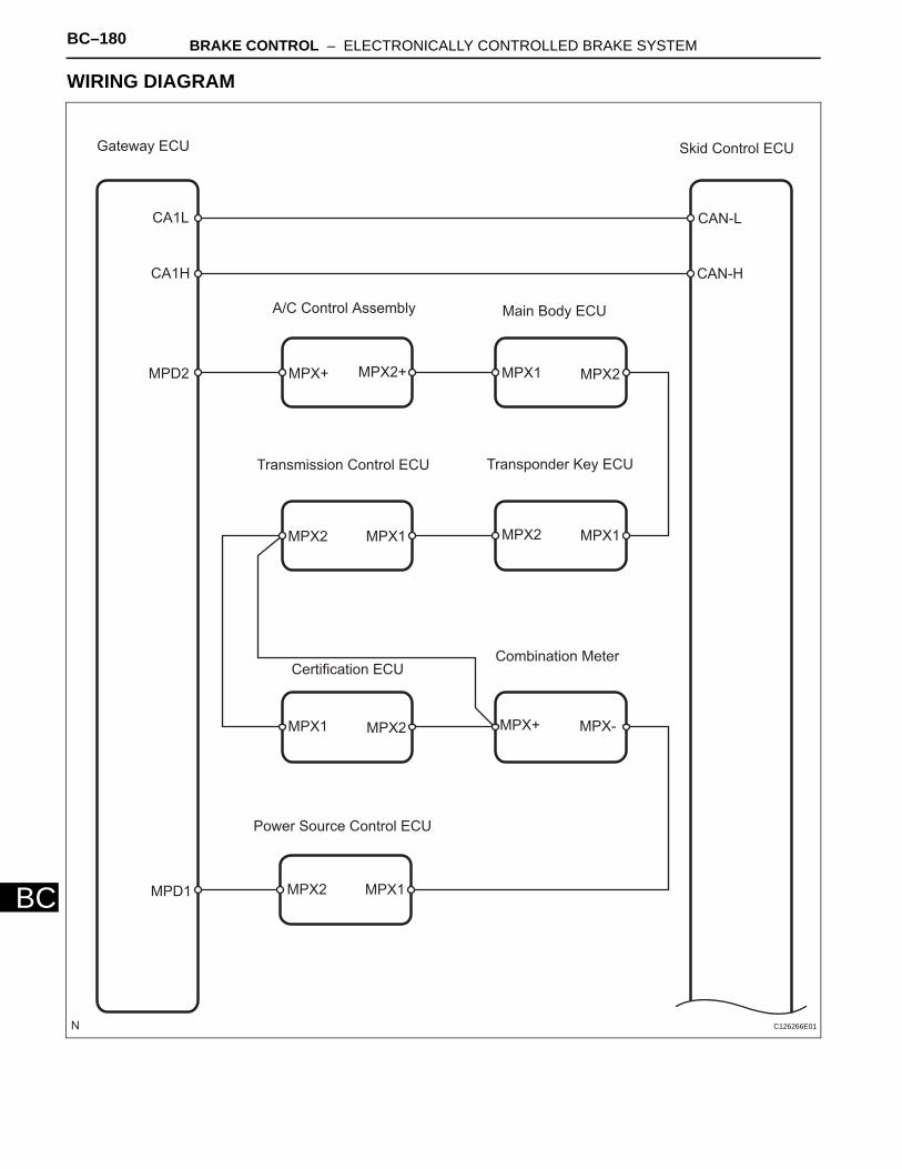
BC–180 BRAKE CONTROL – ELECTRONICALLY CONTROLLED BRAKE SYSTEM
BC
WIRING DIAGRAM
Gateway ECU Skid Control ECU
CAN-L
CAN-H
CA1L
CA1H
MPD2
A/C Control Assembly Main Body ECU
MPX1 MPX2MPX+ MPX2+
Transmission Control ECU Transponder Key ECU
MPX1MPX2MPX1MPX2
Certification ECUCombination Meter
MPX1 MPX2 MPX+ MPX-
Power Source Control ECU
MPX1MPX2MPD1
C126266E01
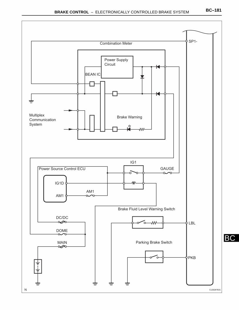
BRAKE CONTROL – ELECTRONICALLY CONTROLLED BRAKE SYSTEM BC–181
BC
Combination MeterSP1-
Power Supply
Circuit
BEAN IC
Multiplex
Communication
System
Brake Warning
IG1
GAUGEPower Source Control ECU
IG1D
AM1AM1
DC/DC
DOME
MAIN
Brake Fluid Level Warning Switch
LBL
PKB
Parking Brake Switch
C126267E01
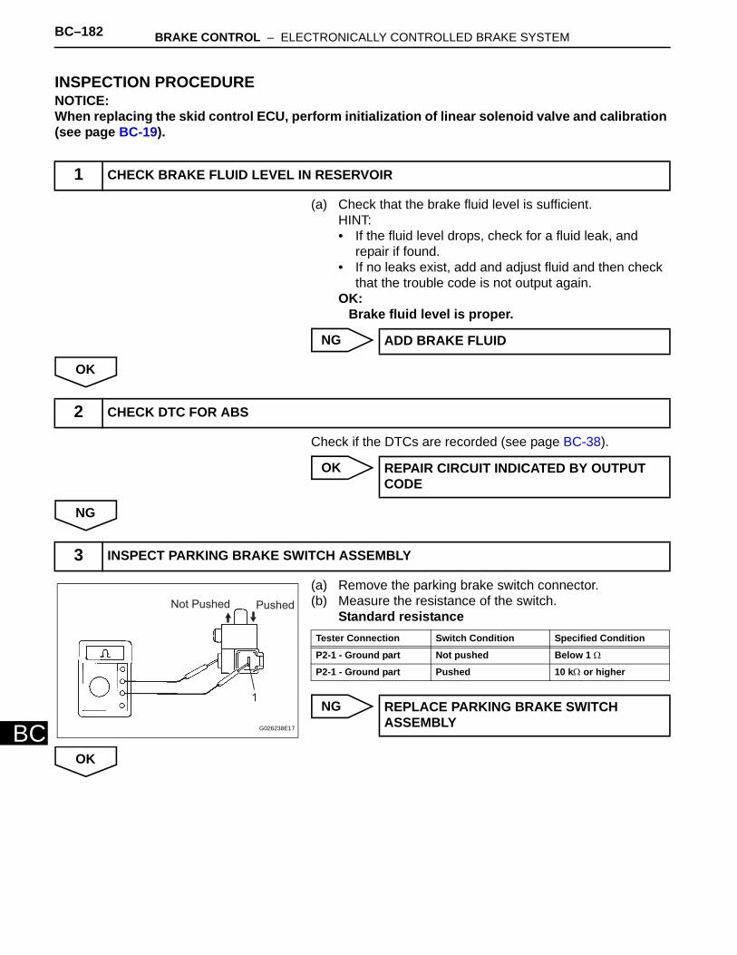
BC–182 BRAKE CONTROL – ELECTRONICALLY CONTROLLED BRAKE SYSTEM
BC
INSPECTION PROCEDURENOTICE:When replacing the skid control ECU, perform initialization of linear solenoid valve and calibration (see page BC-19).
(a) Check that the brake fluid level is sufficient.HINT:• If the fluid level drops, check for a fluid leak, and
repair if found. • If no leaks exist, add and adjust fluid and then check
that the trouble code is not output again.OK:
Brake fluid level is proper.
NG
OK
Check if the DTCs are recorded (see page BC-38).
OK
NG
(a) Remove the parking brake switch connector.(b) Measure the resistance of the switch.
Standard resistance
NG
OK
1 CHECK BRAKE FLUID LEVEL IN RESERVOIR
ADD BRAKE FLUID
2 CHECK DTC FOR ABS
REPAIR CIRCUIT INDICATED BY OUTPUT CODE
3 INSPECT PARKING BRAKE SWITCH ASSEMBLY
Not Pushed Pushed
1
G026238E17
Tester Connection Switch Condition Specified Condition
P2-1 - Ground part Not pushed Below 1 Ω
P2-1 - Ground part Pushed 10 kΩ or higher
REPLACE PARKING BRAKE SWITCH ASSEMBLY
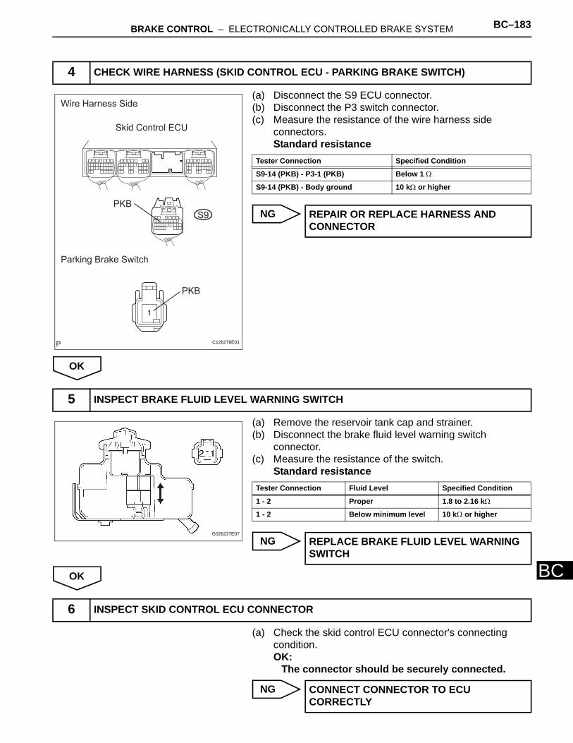
BRAKE CONTROL – ELECTRONICALLY CONTROLLED BRAKE SYSTEM BC–183
BC
(a) Disconnect the S9 ECU connector.(b) Disconnect the P3 switch connector.(c) Measure the resistance of the wire harness side
connectors.Standard resistance
NG
OK
(a) Remove the reservoir tank cap and strainer. (b) Disconnect the brake fluid level warning switch
connector. (c) Measure the resistance of the switch.
Standard resistance
NG
OK
(a) Check the skid control ECU connector's connecting condition.OK:
The connector should be securely connected.
NG
4 CHECK WIRE HARNESS (SKID CONTROL ECU - PARKING BRAKE SWITCH)
Wire Harness Side
Skid Control ECU
PKB
PKB
Parking Brake Switch
S9
C126278E01
Tester Connection Specified Condition
S9-14 (PKB) - P3-1 (PKB) Below 1 Ω
S9-14 (PKB) - Body ground 10 kΩ or higher
REPAIR OR REPLACE HARNESS AND CONNECTOR
5 INSPECT BRAKE FLUID LEVEL WARNING SWITCH
G026237E07
Tester Connection Fluid Level Specified Condition
1 - 2 Proper 1.8 to 2.16 kΩ
1 - 2 Below minimum level 10 kΩ or higher
REPLACE BRAKE FLUID LEVEL WARNING SWITCH
6 INSPECT SKID CONTROL ECU CONNECTOR
CONNECT CONNECTOR TO ECU CORRECTLY
BC–184 BRAKE CONTROL – ELECTRONICALLY CONTROLLED BRAKE SYSTEM
BC
OK
(a) Select the ACTIVE TEST, generate a control command, and then check that the brake warning light operates.
Skid control ECU
OK:The brake warning light turns on or off.
NG
OK
7 PERFORM ACTIVE TEST BY INTELLIGENT TESTER (BRAKE WARNING LIGHT)
Item Test Details Diagnostic Note
BRAKE WARN LIGHT Turns BRAKE warning light ON / OFF Observe combination meter
REPAIR OR REPLACE COMBINATION METER ASSEMBLY
REPLACE SKID CONTROL ECU
BRAKE CONTROL – ELECTRONICALLY CONTROLLED BRAKE SYSTEM BC–185
BC
DESCRIPTIONThe skid control ECU is connected to the combination meter via the CAN and multiplex communications. The brake control warning light illuminates to inform the driver that there is a problem in the ECB, or a problem in the brake system that has no influence on driving.
Brake Control Warning Light Remains ON

BC–186 BRAKE CONTROL – ELECTRONICALLY CONTROLLED BRAKE SYSTEM
BC
WIRING DIAGRAM
Gateway ECU Skid Control ECU
CAN-L
CAN-H
CA1L
CA1H
MPD2
A/C Control Assembly Main Body ECU
MPX+ MPX2+ MPX1 MPX2
Transponder Key ECUTransmission Control ECU
MPX2 MPX1 MPX2 MPX1
Combination MeterCertification ECU
MPX2MPX1 MPX+ MPX-
Power Source Control ECU
MPX2 MPX1MPD1
BS2
BS1
to Brake Control Power Supply
to Brake Control Power Supply
C126264E01

BRAKE CONTROL – ELECTRONICALLY CONTROLLED BRAKE SYSTEM BC–187
BC
Combination
Meter
SP1-
Power Supply
Circuit
SLIP
ABS
Brake Control Warning
VSC
BEAN IC
Multiplex
Communication
System
Power Source Control ECU
IG1D
IG1
AM1AM1
GAUGE
MAINDC/DC
DOME
C126265E01
BC–188 BRAKE CONTROL – ELECTRONICALLY CONTROLLED BRAKE SYSTEM
BC
INSPECTION PROCEDURENOTICE:When replacing the skid control ECU, perform initialization of linear solenoid valve and calibration (see page BC-19).
(a) Measure the voltage of the connectors.HINT:Measure the voltage from behind the connector with the connector connected to the skid control ECU.
NG
OK
(a) Select the ACTIVE TEST, generate a control command, and then check that the brake control warning light operates.
Skid control ECU
OK:The brake control warning light turns on or off.
NG
OK
1 CHECK SKID CONTROL ECU (BS1, BS2 VOLTAGE)
BS1 BS2
S7 S10
F047485E70
Tester Connection Specified Condition
S7-3 (BS1) - Body ground 10 to 14 V
S10-7 (BS2) - Body ground 10 to 14 V
REPAIR OR REPLACE HARNESS AND CONNECTOR
2 PERFORM ACTIVE TEST BY INTELLIGENT TESTER (BRAKE CONTROL WARNING LIGHT)
Item Test Details Diagnostic Note
ECB INDI LIGHT Turns Brake Control warning light ON / OFF Observe combination meter
REPAIR OR REPLACE COMBINATION METER
REPLACE SKID CONTROL ECU
BRAKE CONTROL – ELECTRONICALLY CONTROLLED BRAKE SYSTEM BC–189
BC
INSPECTION PROCEDURE
(a) Check if a CAN communication system DTC is output (see page CA-6).Result
B
A
(a) Check if a multiplex communication system DTC is output (see page MP-7 ).Result
B
A
Brake Control Warning Light does not Come ON
1 CHECK CAN COMMUNICATION SYSTEM
Result Proceed to
DTC is not output A
DTC is output B
REPAIR CAN COMMUNICATION SYSTEM
2 CHECK MULTIPLEX COMMUNICATION SYSTEM
Result Proceed to
DTC is not output A
DTC is output B
REPAIR MULTIPLEX COMMUNICATION SYSTEM
REPAIR OR REPLACE COMBINATION METER ASSEMBLY
BC–190 BRAKE CONTROL – ELECTRONICALLY CONTROLLED BRAKE SYSTEM
BC
DESCRIPTIONThe SLIP indicator blinks during Enhanced VSC operation. The skid control ECU is connected to the combination meter via the CAN and multiplex communications.
Slip Indicator Light Circuit

BRAKE CONTROL – ELECTRONICALLY CONTROLLED BRAKE SYSTEM BC–191
BC
WIRING DIAGRAM
Gateway ECU Skid Control ECU
CAN-L
CAN-H
CA1L
CA1H
MPD2
A/C Control Assembly Main Body ECU
MPX1 MPX2MPX+ MPX2+
Transmission Control ECU Transponder Key ECU
MPX1MPX2MPX1MPX2
Certification ECUCombination Meter
MPX1 MPX2 MPX+ MPX-
Power Source Control ECU
MPX1MPX2MPD1
C126266E01

BC–192 BRAKE CONTROL – ELECTRONICALLY CONTROLLED BRAKE SYSTEM
BC
Combination
Meter
SP1-
Power Supply
Circuit
SLIP
ABS
Brake Control Warning
VSC
BEAN IC
Multiplex
Communication
System
Power Source Control ECU
IG1D
IG1
AM1AM1
GAUGE
MAINDC/DC
DOME
C126265E01
BRAKE CONTROL – ELECTRONICALLY CONTROLLED BRAKE SYSTEM BC–193
BC
INSPECTION PROCEDURENOTICE:When replacing the skid control ECU, perform initialization of linear solenoid valve and calibration (see page BC-19).
(a) Select the ACTIVE TEST, generate a control command, and then check that the SLIP indicator light operates.
Skid control ECU
OK:Turn the SLIP indicator light on or off.
OK
NG
(a) Check if a CAN communication system DTC is output (see page CA-16).Result
B
A
(a) Check if a multiplex communication system DTC is output.Result
B
A
1 PERFORM ACTIVE TEST BY INTELLIGENT TESTER (SLIP INDICATOR LIGHT)
Item Test Details Diagnostic Note
SLIP INDI LIGHT Turns SLIP indicator light ON / OFF Observe combination meter
REPLACE SKID CONTROL ECU
2 CHECK CAN COMMUNICATION SYSTEM
Result Proceed to
DTC is not output A
DTC is output B
REPAIR CAN COMMUNICATION SYSTEM
3 CHECK MULTIPLEX COMMUNICATION SYSTEM
Result Proceed to
DTC is not output A
DTC is output B
REPAIR MULTIPLEX COMMUNICATION SYSTEM
REPAIR OR REPLACE COMBINATION METER ASSEMBLY
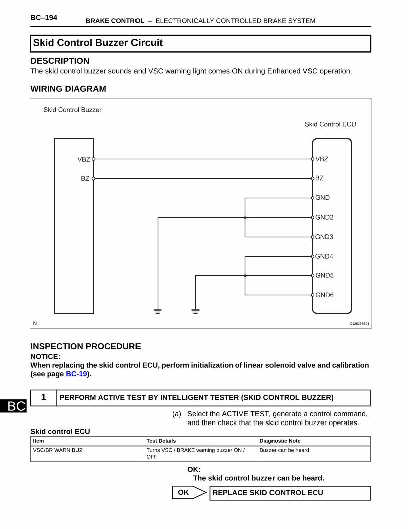
BC–194 BRAKE CONTROL – ELECTRONICALLY CONTROLLED BRAKE SYSTEM
BC
DESCRIPTIONThe skid control buzzer sounds and VSC warning light comes ON during Enhanced VSC operation.
WIRING DIAGRAM
INSPECTION PROCEDURENOTICE:When replacing the skid control ECU, perform initialization of linear solenoid valve and calibration (see page BC-19).
(a) Select the ACTIVE TEST, generate a control command, and then check that the skid control buzzer operates.
Skid control ECU
OK:The skid control buzzer can be heard.
OK
Skid Control Buzzer Circuit
1 PERFORM ACTIVE TEST BY INTELLIGENT TESTER (SKID CONTROL BUZZER)
Skid Control Buzzer
Skid Control ECU
VBZ
BZ
GND
GND2
GND3
GND4
GND5
GND6
VBZ
BZ
C126268E01
Item Test Details Diagnostic Note
VSC/BR WARN BUZ Turns VSC / BRAKE warning buzzer ON / OFF
Buzzer can be heard
REPLACE SKID CONTROL ECU
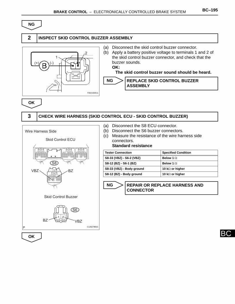
BRAKE CONTROL – ELECTRONICALLY CONTROLLED BRAKE SYSTEM BC–195
BC
NG
(a) Disconnect the skid control buzzer connector. (b) Apply a battery positive voltage to terminals 1 and 2 of
the skid control buzzer connector, and check that the buzzer sounds.OK:
The skid control buzzer sound should be heard.
NG
OK
(a) Disconnect the S8 ECU connector.(b) Disconnect the S6 buzzer connectors.(c) Measure the resistance of the wire harness side
connectors.Standard resistance
NG
OK
2 INSPECT SKID CONTROL BUZZER ASSEMBLY
(+) (-)
12
F002192E11
REPLACE SKID CONTROL BUZZER ASSEMBLY
3 CHECK WIRE HARNESS (SKID CONTROL ECU - SKID CONTROL BUZZER)
Wire Harness Side
Skid Control ECU
S8
VBZ BZ
Skid Control Buzzer
VBZBZ
S6
C126279E01
Tester Connection Specified Condition
S8-33 (VBZ) - S6-2 (VBZ) Below 1 Ω
S8-12 (BZ) - S6-1 (BZ) Below 1 Ω
S8-33 (VBZ) - Body ground 10 kΩ or higher
S8-12 (BZ) - Body ground 10 kΩ or higher
REPAIR OR REPLACE HARNESS AND CONNECTOR
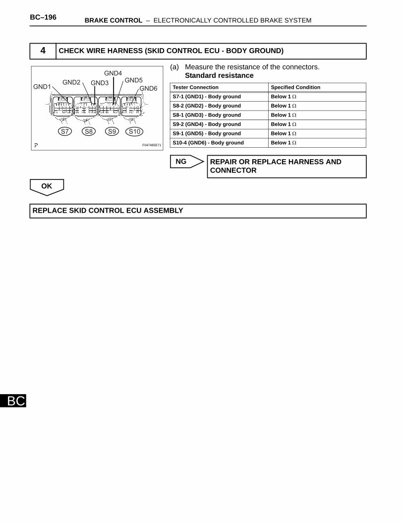
BC–196 BRAKE CONTROL – ELECTRONICALLY CONTROLLED BRAKE SYSTEM
BC
(a) Measure the resistance of the connectors.Standard resistance
NG
OK
4 CHECK WIRE HARNESS (SKID CONTROL ECU - BODY GROUND)
GND1GND5
GND6
GND4
GND3GND2
S7 S8 S9 S10
F047485E71
Tester Connection Specified Condition
S7-1 (GND1) - Body ground Below 1 Ω
S8-2 (GND2) - Body ground Below 1 Ω
S8-1 (GND3) - Body ground Below 1 Ω
S9-2 (GND4) - Body ground Below 1 Ω
S9-1 (GND5) - Body ground Below 1 Ω
S10-4 (GND6) - Body ground Below 1 Ω
REPAIR OR REPLACE HARNESS AND CONNECTOR
REPLACE SKID CONTROL ECU ASSEMBLY
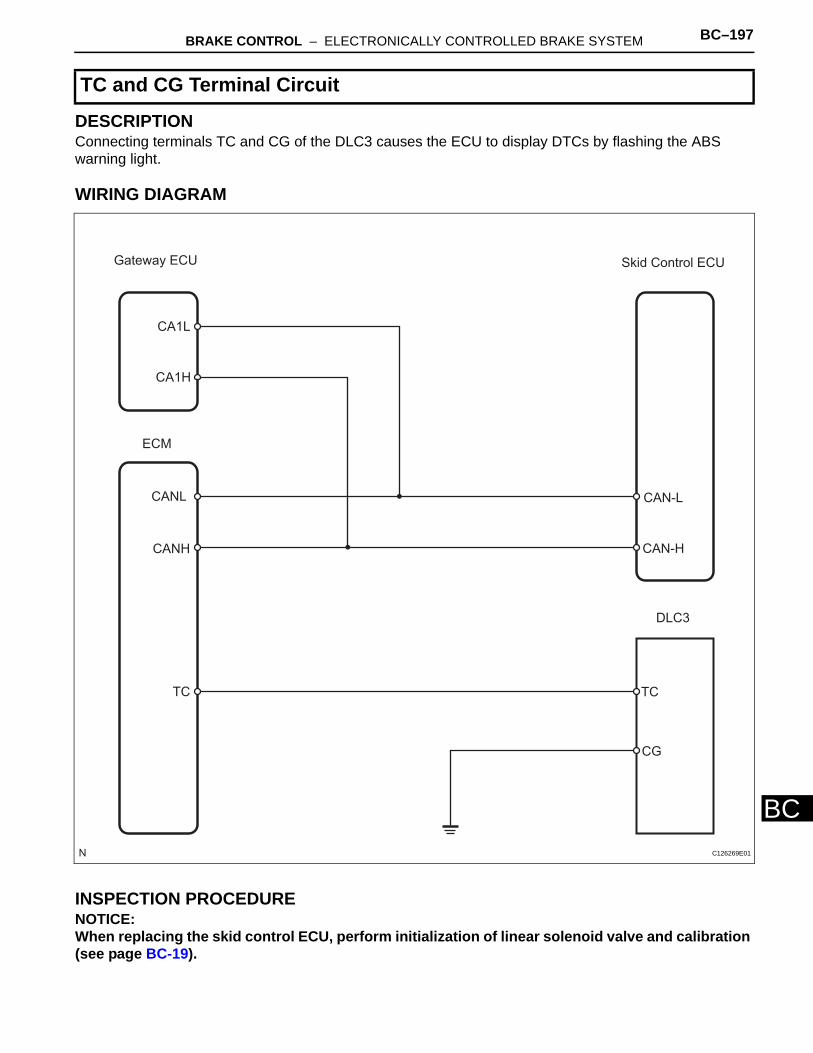
BRAKE CONTROL – ELECTRONICALLY CONTROLLED BRAKE SYSTEM BC–197
BC
DESCRIPTIONConnecting terminals TC and CG of the DLC3 causes the ECU to display DTCs by flashing the ABS warning light.
WIRING DIAGRAM
INSPECTION PROCEDURENOTICE:When replacing the skid control ECU, perform initialization of linear solenoid valve and calibration (see page BC-19).
TC and CG Terminal Circuit
Gateway ECU Skid Control ECU
CA1L
CA1H
ECM
CANL
CANH
CAN-L
CAN-H
DLC3
TC
CG
TC
C126269E01
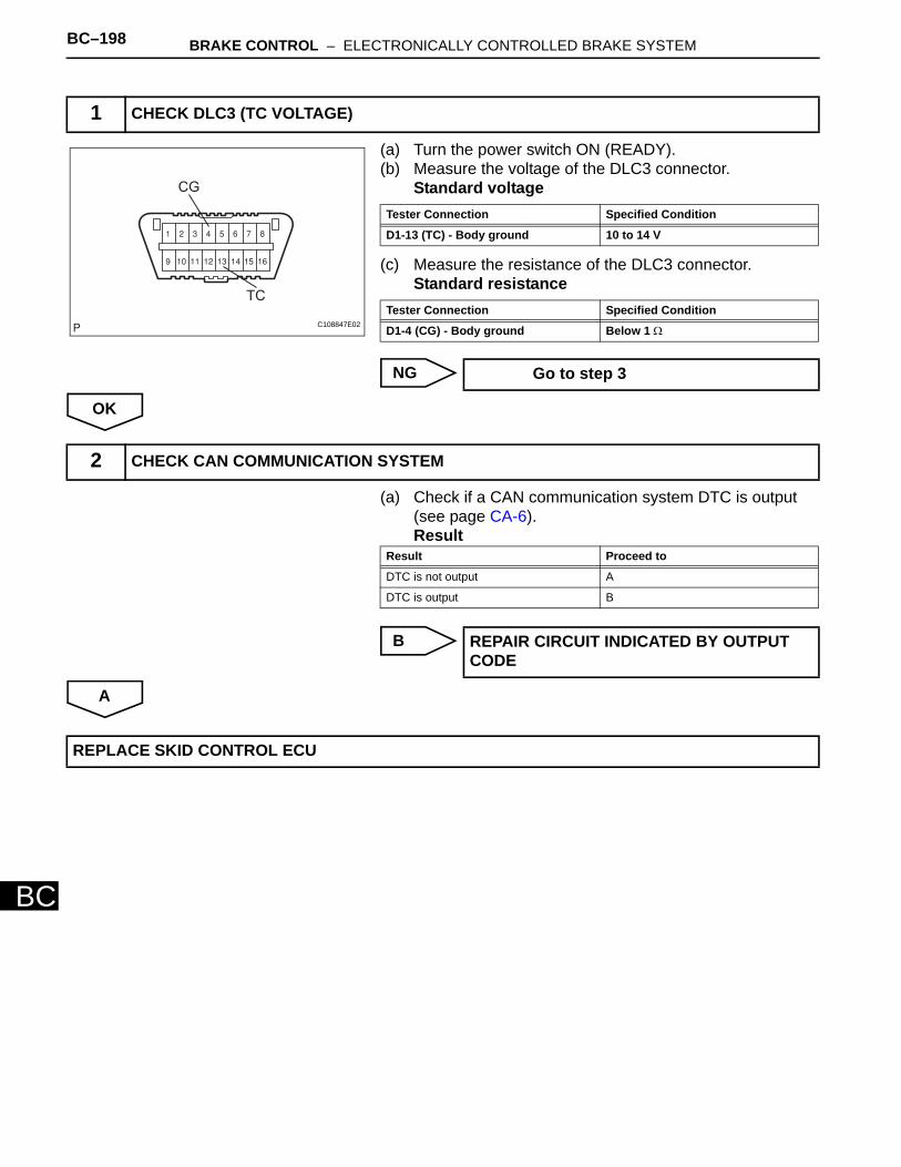
BC–198 BRAKE CONTROL – ELECTRONICALLY CONTROLLED BRAKE SYSTEM
BC
(a) Turn the power switch ON (READY). (b) Measure the voltage of the DLC3 connector.
Standard voltage
(c) Measure the resistance of the DLC3 connector.Standard resistance
NG
OK
(a) Check if a CAN communication system DTC is output (see page CA-6).Result
B
A
1 CHECK DLC3 (TC VOLTAGE)
CG
TC
C108847E02
Tester Connection Specified Condition
D1-13 (TC) - Body ground 10 to 14 V
Tester Connection Specified Condition
D1-4 (CG) - Body ground Below 1 Ω
Go to step 3
2 CHECK CAN COMMUNICATION SYSTEM
Result Proceed to
DTC is not output A
DTC is output B
REPAIR CIRCUIT INDICATED BY OUTPUT CODE
REPLACE SKID CONTROL ECU
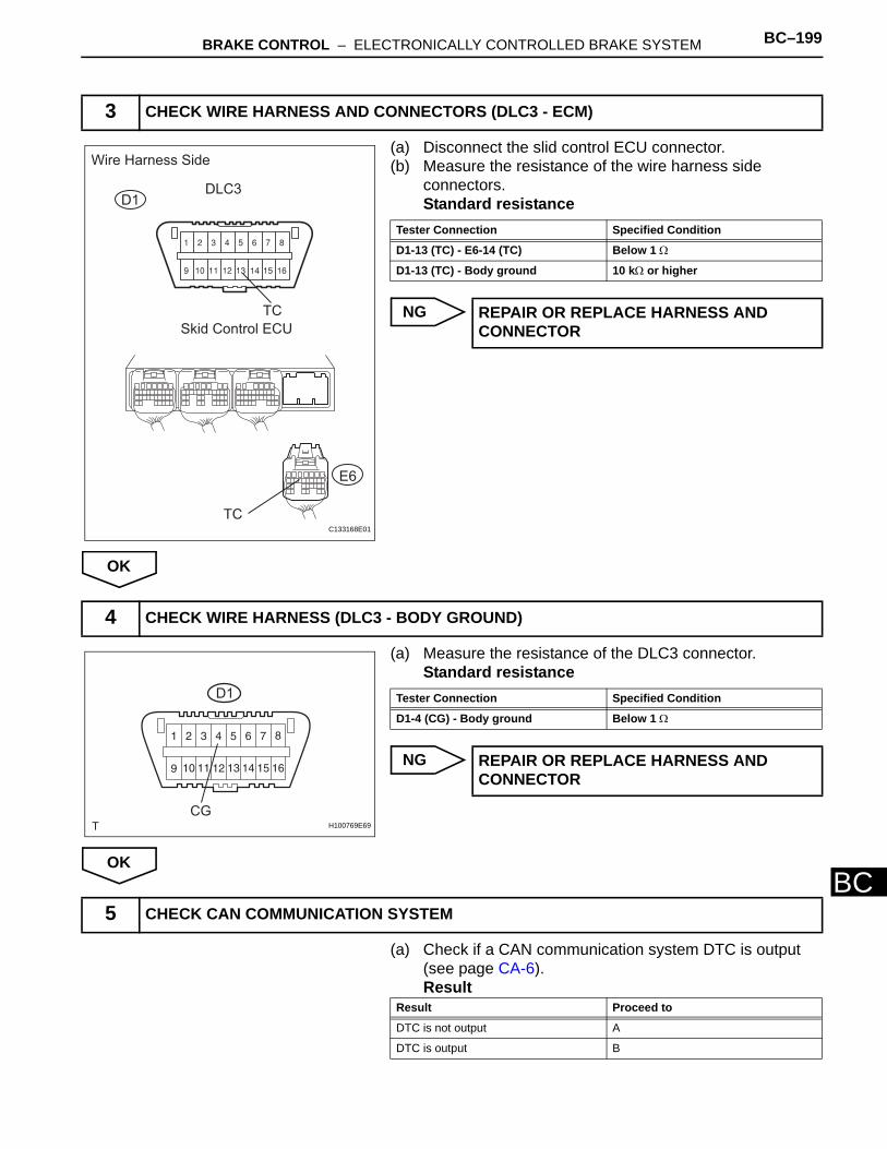
BRAKE CONTROL – ELECTRONICALLY CONTROLLED BRAKE SYSTEM BC–199
BC
(a) Disconnect the slid control ECU connector. (b) Measure the resistance of the wire harness side
connectors.Standard resistance
NG
OK
(a) Measure the resistance of the DLC3 connector.Standard resistance
NG
OK
(a) Check if a CAN communication system DTC is output (see page CA-6).Result
3 CHECK WIRE HARNESS AND CONNECTORS (DLC3 - ECM)
Wire Harness Side
DLC3
TC
Skid Control ECU
TC
E6
D1
C133168E01
Tester Connection Specified Condition
D1-13 (TC) - E6-14 (TC) Below 1 Ω
D1-13 (TC) - Body ground 10 kΩ or higher
REPAIR OR REPLACE HARNESS AND CONNECTOR
4 CHECK WIRE HARNESS (DLC3 - BODY GROUND)
D1
CGH100769E69
Tester Connection Specified Condition
D1-4 (CG) - Body ground Below 1 Ω
REPAIR OR REPLACE HARNESS AND CONNECTOR
5 CHECK CAN COMMUNICATION SYSTEM
Result Proceed to
DTC is not output A
DTC is output B
BC–200 BRAKE CONTROL – ELECTRONICALLY CONTROLLED BRAKE SYSTEM
BC
B
A
REPAIR CIRCUIT INDICATED BY OUTPUT CODE
REPLACE SKID CONTROL ECU
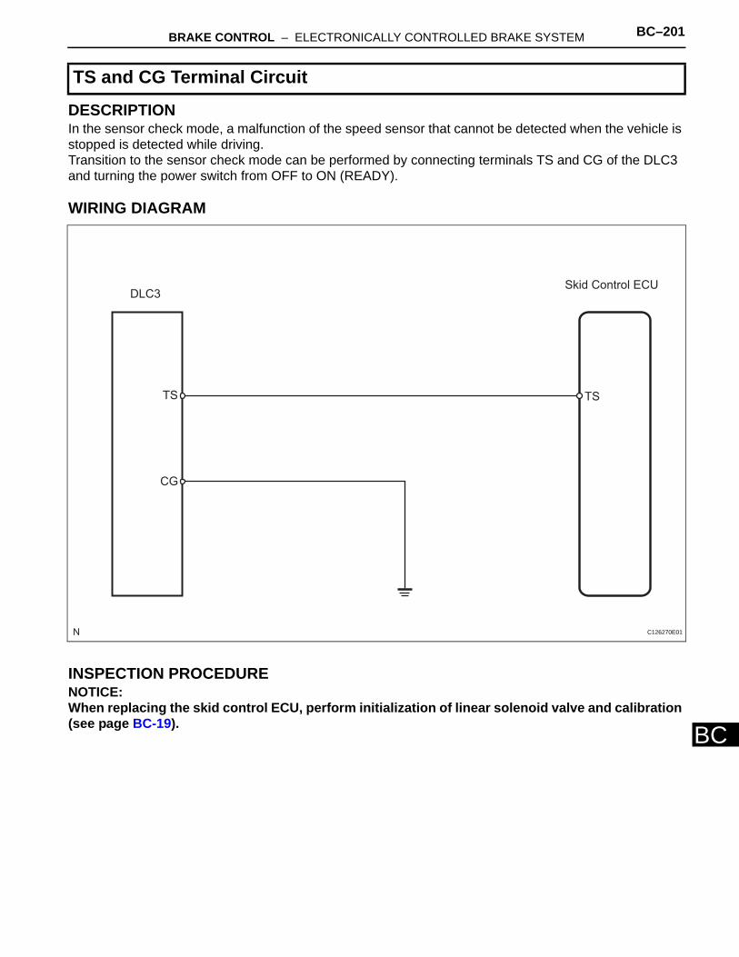
BRAKE CONTROL – ELECTRONICALLY CONTROLLED BRAKE SYSTEM BC–201
BC
DESCRIPTIONIn the sensor check mode, a malfunction of the speed sensor that cannot be detected when the vehicle is stopped is detected while driving. Transition to the sensor check mode can be performed by connecting terminals TS and CG of the DLC3 and turning the power switch from OFF to ON (READY).
WIRING DIAGRAM
INSPECTION PROCEDURENOTICE:When replacing the skid control ECU, perform initialization of linear solenoid valve and calibration (see page BC-19).
TS and CG Terminal Circuit
DLC3Skid Control ECU
TSTS
CG
C126270E01
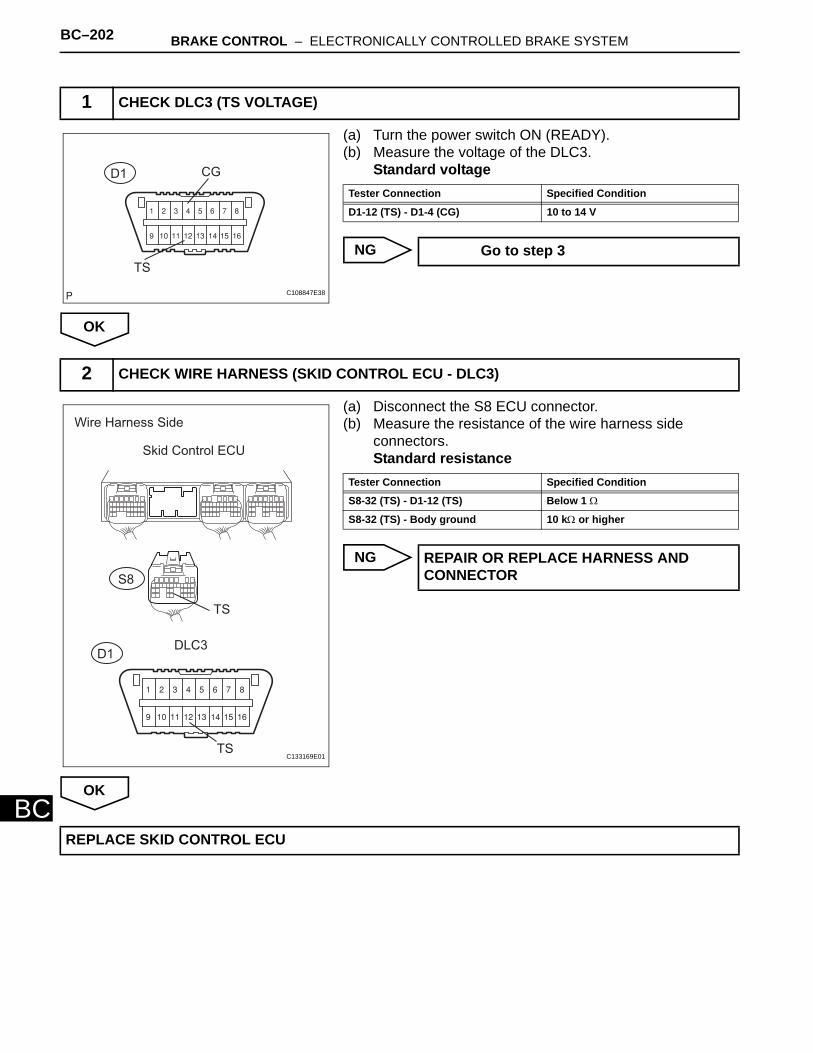
BC–202 BRAKE CONTROL – ELECTRONICALLY CONTROLLED BRAKE SYSTEM
BC
(a) Turn the power switch ON (READY). (b) Measure the voltage of the DLC3.
Standard voltage
NG
OK
(a) Disconnect the S8 ECU connector. (b) Measure the resistance of the wire harness side
connectors.Standard resistance
NG
OK
1 CHECK DLC3 (TS VOLTAGE)
CG
TS
D1
C108847E38
Tester Connection Specified Condition
D1-12 (TS) - D1-4 (CG) 10 to 14 V
Go to step 3
2 CHECK WIRE HARNESS (SKID CONTROL ECU - DLC3)
Wire Harness Side
Skid Control ECU
S8
TS
DLC3
TS
D1
C133169E01
Tester Connection Specified Condition
S8-32 (TS) - D1-12 (TS) Below 1 Ω
S8-32 (TS) - Body ground 10 kΩ or higher
REPAIR OR REPLACE HARNESS AND CONNECTOR
REPLACE SKID CONTROL ECU
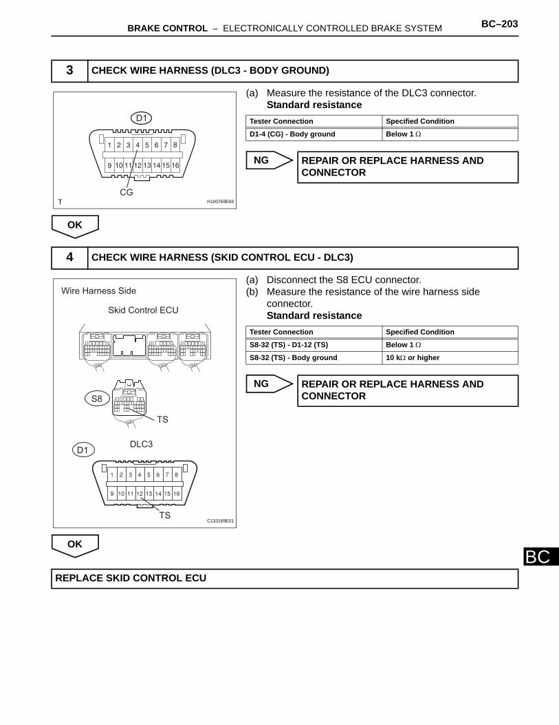
BRAKE CONTROL – ELECTRONICALLY CONTROLLED BRAKE SYSTEM BC–203
BC
(a) Measure the resistance of the DLC3 connector.Standard resistance
NG
OK
(a) Disconnect the S8 ECU connector.(b) Measure the resistance of the wire harness side
connector.Standard resistance
NG
OK
3 CHECK WIRE HARNESS (DLC3 - BODY GROUND)
D1
CGH100769E69
Tester Connection Specified Condition
D1-4 (CG) - Body ground Below 1 Ω
REPAIR OR REPLACE HARNESS AND CONNECTOR
4 CHECK WIRE HARNESS (SKID CONTROL ECU - DLC3)
Wire Harness Side
Skid Control ECU
S8
TS
DLC3
TS
D1
C133169E01
Tester Connection Specified Condition
S8-32 (TS) - D1-12 (TS) Below 1 Ω
S8-32 (TS) - Body ground 10 kΩ or higher
REPAIR OR REPLACE HARNESS AND CONNECTOR
REPLACE SKID CONTROL ECU
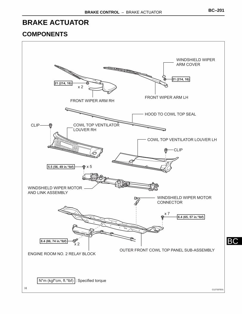
BRAKE CONTROL – BRAKE ACTUATOR BC–201
C
BBRAKEBRAKE CONTROLBRAKE ACTUATORCOMPONENTS
COWL TOP VENTILATOR LOUVER LH
COWL TOP VENTILATOR
LOUVER RH
FRONT WIPER ARM LHFRONT WIPER ARM RH
HOOD TO COWL TOP SEAL
OUTER FRONT COWL TOP PANEL SUB-ASSEMBLY
WINDSHIELD WIPER MOTOR
AND LINK ASSEMBLY
WINDSHIELD WIPER
ARM COVER
CLIP
CLIP
x 2
x 5
WINDSHIELD WIPER MOTOR
CONNECTOR
x 7
ENGINE ROOM NO. 2 RELAY BLOCK
x 2
: Specified torqueN*m (kgf*cm, ft.*lbf)
21 (214, 16)
5.5 (56, 49 in.*lbf)
21 (214, 16)
6.4 (65, 57 in.*lbf)
8.4 (86, 74 in.*lbf)
C127337E01
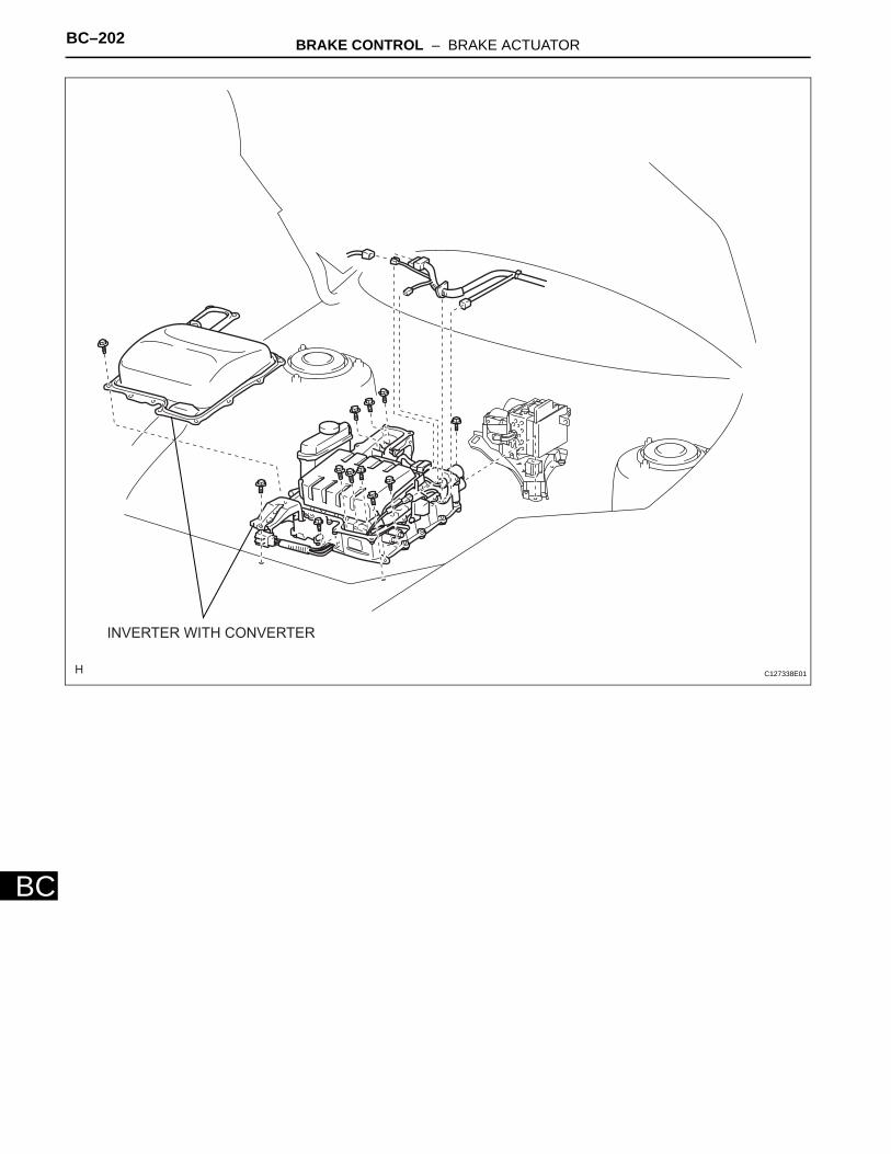
BC–202 BRAKE CONTROL – BRAKE ACTUATOR
BC
INVERTER WITH CONVERTER
C127338E01
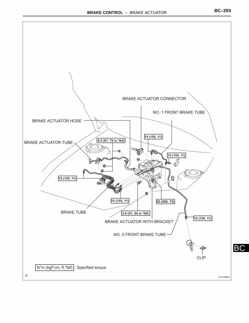
BRAKE CONTROL – BRAKE ACTUATOR BC–203
C
BBRAKE ACTUATOR WITH BRACKET
BRAKE ACTUATOR TUBE
BRAKE ACTUATOR HOSE
BRAKE ACTUATOR CONNECTOR
NO. 1 FRONT BRAKE TUBE
NO. 5 FRONT BRAKE TUBE
BRAKE TUBE
: Specified torqueN*m (kgf*cm, ft.*lbf)
15 (155, 11)
5.0 (51, 44 in.*lbf)
15 (155, 11)
15 (155, 11)
15 (155, 11)
15 (155, 11)
8.5 (87, 75 in.*lbf)
20 (200, 15)
CLIP
C127339E01
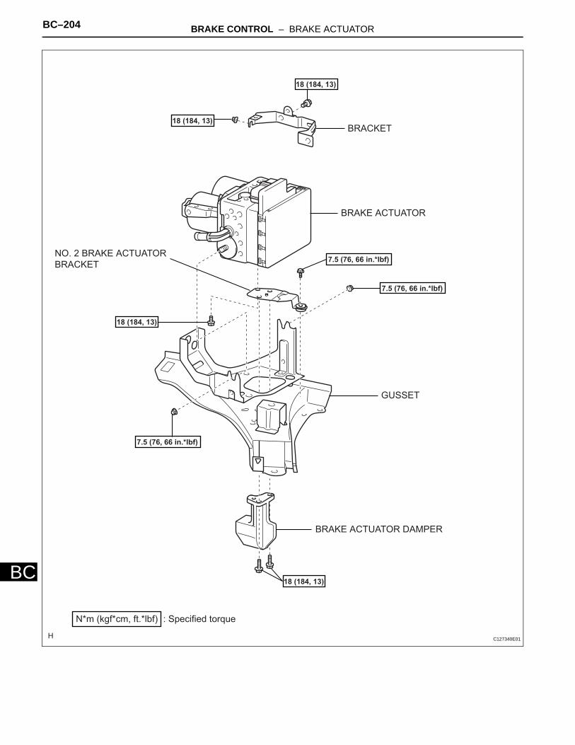
BC–204 BRAKE CONTROL – BRAKE ACTUATOR
BC
BRAKE ACTUATOR
BRACKET
NO. 2 BRAKE ACTUATOR
BRACKET
GUSSET
BRAKE ACTUATOR DAMPER
: Specified torqueN*m (kgf*cm, ft.*lbf)
18 (184, 13)
7.5 (76, 66 in.*lbf)
18 (184, 13)
7.5 (76, 66 in.*lbf)
18 (184, 13)
7.5 (76, 66 in.*lbf)
18 (184, 13)
C127340E01
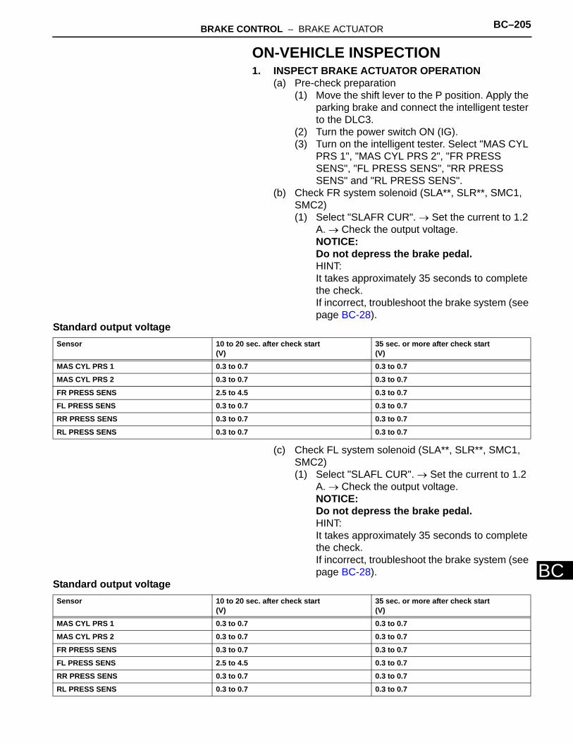
BRAKE CONTROL – BRAKE ACTUATOR BC–205
C
BON-VEHICLE INSPECTION1. INSPECT BRAKE ACTUATOR OPERATION
(a) Pre-check preparation(1) Move the shift lever to the P position. Apply the
parking brake and connect the intelligent tester to the DLC3.
(2) Turn the power switch ON (IG).(3) Turn on the intelligent tester. Select "MAS CYL
PRS 1", "MAS CYL PRS 2", "FR PRESS SENS", "FL PRESS SENS", "RR PRESS SENS" and "RL PRESS SENS".
(b) Check FR system solenoid (SLA**, SLR**, SMC1, SMC2)(1) Select "SLAFR CUR". → Set the current to 1.2
A. → Check the output voltage.NOTICE:Do not depress the brake pedal.HINT:It takes approximately 35 seconds to complete the check.If incorrect, troubleshoot the brake system (see page BC-28).
Standard output voltage
(c) Check FL system solenoid (SLA**, SLR**, SMC1, SMC2)(1) Select "SLAFL CUR". → Set the current to 1.2
A. → Check the output voltage.NOTICE:Do not depress the brake pedal.HINT:It takes approximately 35 seconds to complete the check.If incorrect, troubleshoot the brake system (see page BC-28).
Standard output voltage
Sensor 10 to 20 sec. after check start(V)
35 sec. or more after check start(V)
MAS CYL PRS 1 0.3 to 0.7 0.3 to 0.7
MAS CYL PRS 2 0.3 to 0.7 0.3 to 0.7
FR PRESS SENS 2.5 to 4.5 0.3 to 0.7
FL PRESS SENS 0.3 to 0.7 0.3 to 0.7
RR PRESS SENS 0.3 to 0.7 0.3 to 0.7
RL PRESS SENS 0.3 to 0.7 0.3 to 0.7
Sensor 10 to 20 sec. after check start(V)
35 sec. or more after check start(V)
MAS CYL PRS 1 0.3 to 0.7 0.3 to 0.7
MAS CYL PRS 2 0.3 to 0.7 0.3 to 0.7
FR PRESS SENS 0.3 to 0.7 0.3 to 0.7
FL PRESS SENS 2.5 to 4.5 0.3 to 0.7
RR PRESS SENS 0.3 to 0.7 0.3 to 0.7
RL PRESS SENS 0.3 to 0.7 0.3 to 0.7
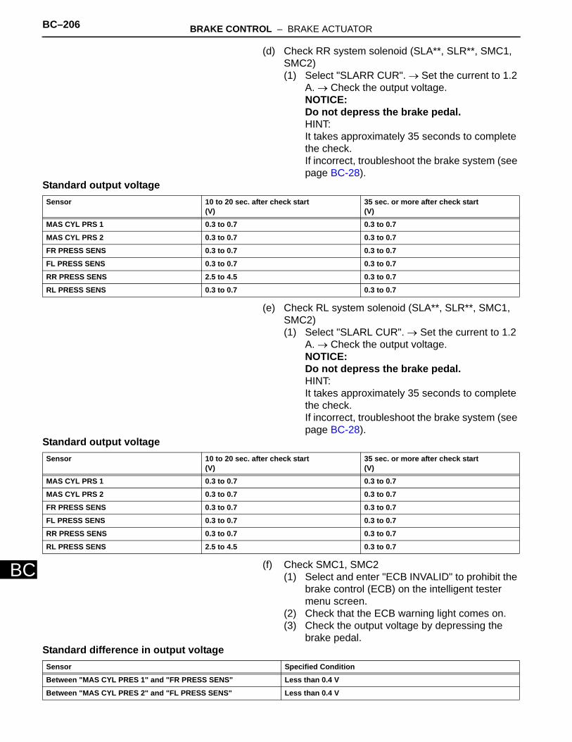
BC–206 BRAKE CONTROL – BRAKE ACTUATOR
BC
(d) Check RR system solenoid (SLA**, SLR**, SMC1, SMC2)(1) Select "SLARR CUR". → Set the current to 1.2
A. → Check the output voltage.NOTICE:Do not depress the brake pedal.HINT:It takes approximately 35 seconds to complete the check.If incorrect, troubleshoot the brake system (see page BC-28).
Standard output voltage
(e) Check RL system solenoid (SLA**, SLR**, SMC1, SMC2)(1) Select "SLARL CUR". → Set the current to 1.2
A. → Check the output voltage.NOTICE:Do not depress the brake pedal.HINT:It takes approximately 35 seconds to complete the check.If incorrect, troubleshoot the brake system (see page BC-28).
Standard output voltage
(f) Check SMC1, SMC2(1) Select and enter "ECB INVALID" to prohibit the
brake control (ECB) on the intelligent tester menu screen.
(2) Check that the ECB warning light comes on.(3) Check the output voltage by depressing the
brake pedal.Standard difference in output voltage
Sensor 10 to 20 sec. after check start(V)
35 sec. or more after check start(V)
MAS CYL PRS 1 0.3 to 0.7 0.3 to 0.7
MAS CYL PRS 2 0.3 to 0.7 0.3 to 0.7
FR PRESS SENS 0.3 to 0.7 0.3 to 0.7
FL PRESS SENS 0.3 to 0.7 0.3 to 0.7
RR PRESS SENS 2.5 to 4.5 0.3 to 0.7
RL PRESS SENS 0.3 to 0.7 0.3 to 0.7
Sensor 10 to 20 sec. after check start(V)
35 sec. or more after check start(V)
MAS CYL PRS 1 0.3 to 0.7 0.3 to 0.7
MAS CYL PRS 2 0.3 to 0.7 0.3 to 0.7
FR PRESS SENS 0.3 to 0.7 0.3 to 0.7
FL PRESS SENS 0.3 to 0.7 0.3 to 0.7
RR PRESS SENS 0.3 to 0.7 0.3 to 0.7
RL PRESS SENS 2.5 to 4.5 0.3 to 0.7
Sensor Specified Condition
Between "MAS CYL PRES 1" and "FR PRESS SENS" Less than 0.4 V
Between "MAS CYL PRES 2" and "FL PRESS SENS" Less than 0.4 V
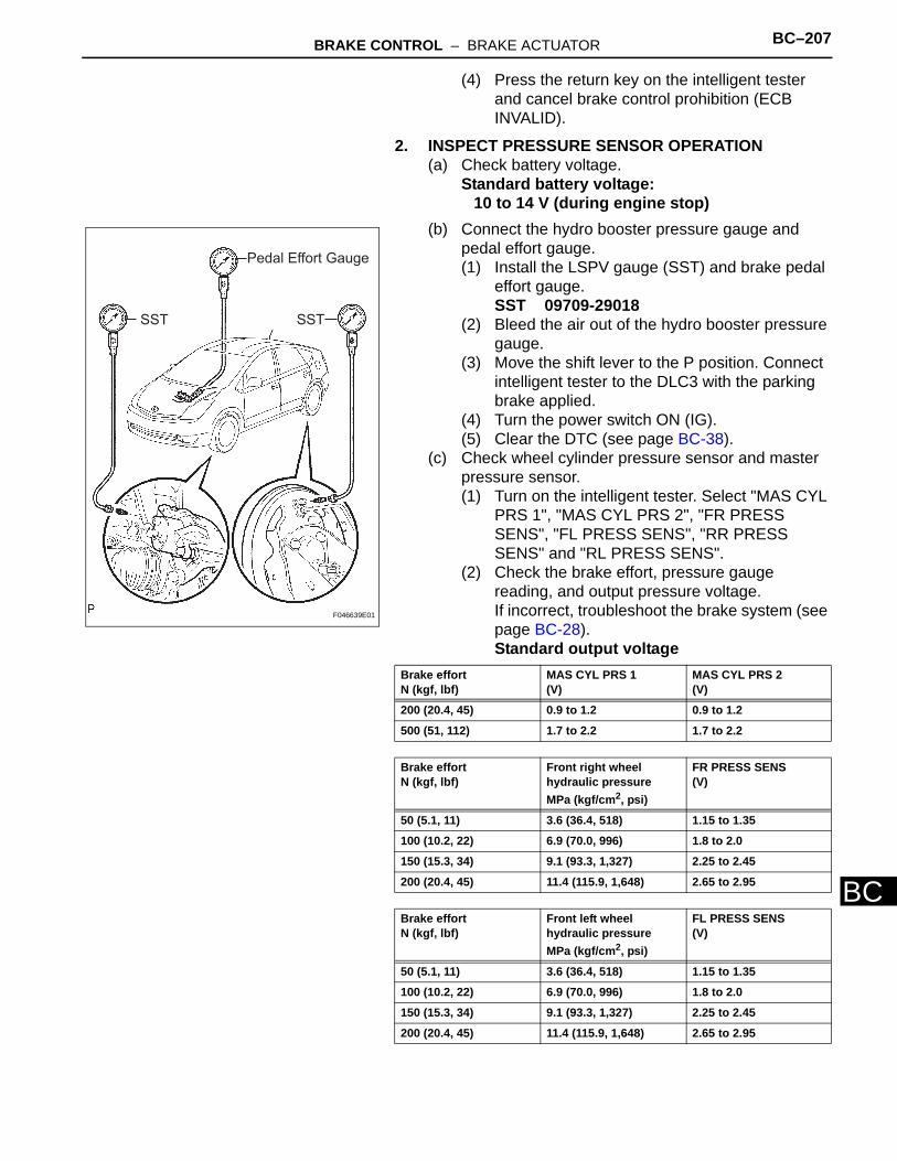
BRAKE CONTROL – BRAKE ACTUATOR BC–207
C
B(4) Press the return key on the intelligent tester and cancel brake control prohibition (ECB INVALID).
2. INSPECT PRESSURE SENSOR OPERATION(a) Check battery voltage.
Standard battery voltage:10 to 14 V (during engine stop)
(b) Connect the hydro booster pressure gauge and pedal effort gauge.(1) Install the LSPV gauge (SST) and brake pedal
effort gauge.SST 09709-29018
(2) Bleed the air out of the hydro booster pressure gauge.
(3) Move the shift lever to the P position. Connect intelligent tester to the DLC3 with the parking brake applied.
(4) Turn the power switch ON (IG).(5) Clear the DTC (see page BC-38).
(c) Check wheel cylinder pressure sensor and master pressure sensor.(1) Turn on the intelligent tester. Select "MAS CYL
PRS 1", "MAS CYL PRS 2", "FR PRESS SENS", "FL PRESS SENS", "RR PRESS SENS" and "RL PRESS SENS".
(2) Check the brake effort, pressure gauge reading, and output pressure voltage.If incorrect, troubleshoot the brake system (see page BC-28).Standard output voltage
SST SST
Pedal Effort Gauge
F046639E01
Brake effortN (kgf, lbf)
MAS CYL PRS 1(V)
MAS CYL PRS 2(V)
200 (20.4, 45) 0.9 to 1.2 0.9 to 1.2
500 (51, 112) 1.7 to 2.2 1.7 to 2.2
Brake effortN (kgf, lbf)
Front right wheel hydraulic pressureMPa (kgf/cm2, psi)
FR PRESS SENS(V)
50 (5.1, 11) 3.6 (36.4, 518) 1.15 to 1.35
100 (10.2, 22) 6.9 (70.0, 996) 1.8 to 2.0
150 (15.3, 34) 9.1 (93.3, 1,327) 2.25 to 2.45
200 (20.4, 45) 11.4 (115.9, 1,648) 2.65 to 2.95
Brake effortN (kgf, lbf)
Front left wheel hydraulic pressureMPa (kgf/cm2, psi)
FL PRESS SENS(V)
50 (5.1, 11) 3.6 (36.4, 518) 1.15 to 1.35
100 (10.2, 22) 6.9 (70.0, 996) 1.8 to 2.0
150 (15.3, 34) 9.1 (93.3, 1,327) 2.25 to 2.45
200 (20.4, 45) 11.4 (115.9, 1,648) 2.65 to 2.95
BC–208 BRAKE CONTROL – BRAKE ACTUATOR
BC
(d) Check accumulator (ACC) pressure sensor.(1) Move the shift lever to the P position. Apply the
parking brake and connect the intelligent tester.(2) Turn the power switch ON (IG).(3) Turn on the intelligent tester. Select the
accumulator (ACC) pressure sensor 1 ("ACC PRESS SENS").
(4) Temporarily operate the pump motor by depressing the brake pedal 4 to 5 times.
(5) After confirming that the pump motor stops, check the pressure output voltage.If incorrect, troubleshoot the brake system (see page BC-28).Standard output voltage:
2.6 to 3.8 V
Brake effortN (kgf, lbf)
Rear right wheel hydraulic pressureMPa (kgf/cm2, psi)
RR PRESS SENS(V)
50 (5.1, 11) 3.9 (39.4, 560) 1.2 to 1.4
100 (10.2, 22) 4 (40.8, 580) 1.25 to 1.5
150 (15.3, 34) 4 (40.8, 580) 1.25 to 1.5
200 (20.4, 45) 4 (40.8, 580) 1.25 to 1.5
Brake effortN (kgf, lbf)
Rear left wheel hydraulic pressureMPa (kgf/cm2, psi)
RL PRESS SENS(V)
50 (5.1, 11) 3.9 (39.4, 560) 1.2 to 1.4
100 (10.2, 22) 4 (40.8, 580) 1.25 to 1.5
150 (15.3, 34) 4 (40.8, 580) 1.25 to 1.5
200 (20.4, 45) 4 (40.8, 580) 1.25 to 1.5
BRAKE CONTROL – BRAKE ACTUATOR BC–209
C
BREPLACEMENTNOTICE:Be sure to replace the actuator and the resistor together. If they are not replaced together, motor noise may be increased.1. REPLACE BRAKE ACTUATOR ASSEMBLY
(a) Remove the windshield wiper motor and link (see page WW-13).HINT:Refer to the procedures from the removal of the front wiper arm LH/RH up until the removal of the windshield wiper motor and link assembly.
(b) Perform the accumulator pressure "ZERO DOWN" operation.NOTICE:Carry out the accumulator "ZERO DOWN" operation and lower the internal pressure before removing the brake actuator.(1) Move the shift lever to the P position. Apply the
parking brake and connect the intelligent tester to the DLC3.
(2) Turn the power switch ON (IG).(3) Turn on the intelligent tester. Select "ZERO
DOWN".NOTICE:Keep the fluid inside the reservoir above the "LOW" level by replenishing.HINT:• Accumulator pressure is released and
accumulated repeatedly, which circulates the fluid inside the accumulator when performing this procedure.
• The pump motor rotates and the accumulator is pressurized every time turning the power switch from OFF to ON (IG).
(4) Turn the power switch OFF.(c) Set the brake control (ECB) off.
NOTICE:• Prohibit the brake control (ECB) before air
bleeding.• Be sure to remove the No. 1 and No. 2 motor
relays first, then the brake actuator.
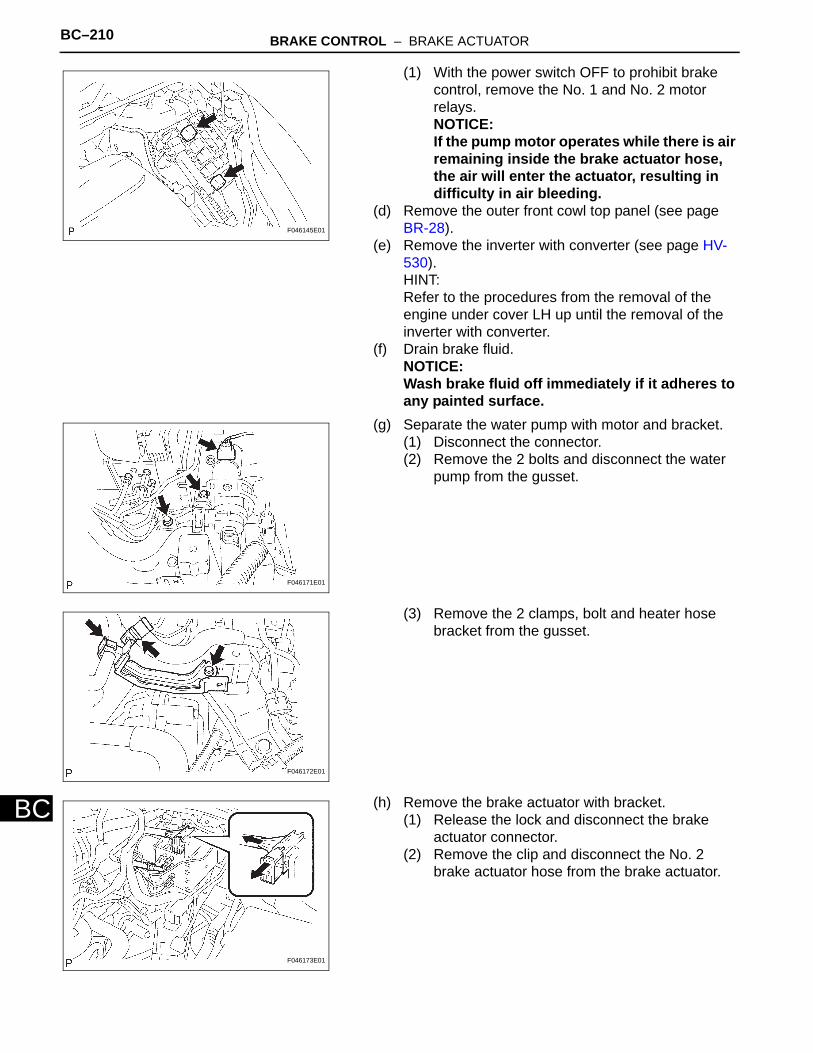
BC–210 BRAKE CONTROL – BRAKE ACTUATOR
BC
(1) With the power switch OFF to prohibit brake control, remove the No. 1 and No. 2 motor relays.NOTICE:If the pump motor operates while there is air remaining inside the brake actuator hose, the air will enter the actuator, resulting in difficulty in air bleeding.
(d) Remove the outer front cowl top panel (see page BR-28).
(e) Remove the inverter with converter (see page HV-530).HINT:Refer to the procedures from the removal of the engine under cover LH up until the removal of the inverter with converter.
(f) Drain brake fluid.NOTICE:Wash brake fluid off immediately if it adheres to any painted surface.
(g) Separate the water pump with motor and bracket.(1) Disconnect the connector.(2) Remove the 2 bolts and disconnect the water
pump from the gusset.
(3) Remove the 2 clamps, bolt and heater hose bracket from the gusset.
(h) Remove the brake actuator with bracket.(1) Release the lock and disconnect the brake
actuator connector.(2) Remove the clip and disconnect the No. 2
brake actuator hose from the brake actuator.
F046145E01
F046171E01
F046172E01
F046173E01
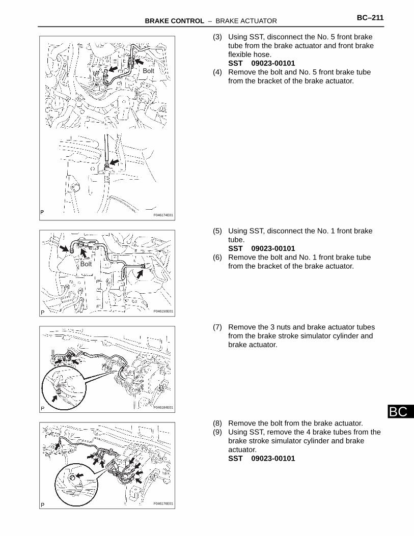
BRAKE CONTROL – BRAKE ACTUATOR BC–211
C
B(3) Using SST, disconnect the No. 5 front brake tube from the brake actuator and front brake flexible hose.SST 09023-00101
(4) Remove the bolt and No. 5 front brake tube from the bracket of the brake actuator.
(5) Using SST, disconnect the No. 1 front brake tube.SST 09023-00101
(6) Remove the bolt and No. 1 front brake tube from the bracket of the brake actuator.
(7) Remove the 3 nuts and brake actuator tubes from the brake stroke simulator cylinder and brake actuator.
(8) Remove the bolt from the brake actuator.(9) Using SST, remove the 4 brake tubes from the
brake stroke simulator cylinder and brake actuator.SST 09023-00101
Bolt
F046174E01
Bolt
F046150E01
F046184E01
F046176E01
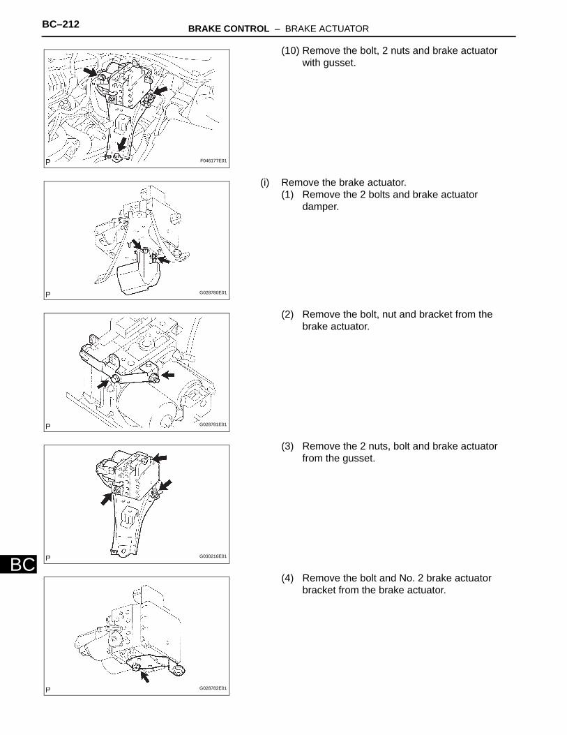
BC–212 BRAKE CONTROL – BRAKE ACTUATOR
BC
(10) Remove the bolt, 2 nuts and brake actuator with gusset.
(i) Remove the brake actuator.(1) Remove the 2 bolts and brake actuator
damper.
(2) Remove the bolt, nut and bracket from the brake actuator.
(3) Remove the 2 nuts, bolt and brake actuator from the gusset.
(4) Remove the bolt and No. 2 brake actuator bracket from the brake actuator.
F046177E01
G028780E01
G028781E01
G030216E01
G028782E01
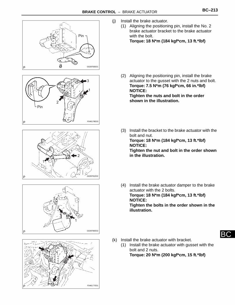
BRAKE CONTROL – BRAKE ACTUATOR BC–213
C
B(j) Install the brake actuator.(1) Aligning the positioning pin, install the No. 2
brake actuator bracket to the brake actuator with the bolt.Torque: 18 N*m (184 kgf*cm, 13 ft.*lbf)
(2) Aligning the positioning pin, install the brake actuator to the gusset with the 2 nuts and bolt.Torque: 7.5 N*m (76 kgf*cm, 66 in.*lbf)NOTICE:Tighten the nuts and bolt in the order shown in the illustration.
(3) Install the bracket to the brake actuator with the bolt and nut.Torque: 18 N*m (184 kgf*cm, 13 ft.*lbf)NOTICE:Tighten the nut and bolt in the order shown in the illustration.
(4) Install the brake actuator damper to the brake actuator with the 2 bolts.Torque: 18 N*m (184 kgf*cm, 13 ft.*lbf)NOTICE:Tighten the bolts in the order shown in the illustration.
(k) Install the brake actuator with bracket.(1) Install the brake actuator with gusset with the
bolt and 2 nuts.Torque: 20 N*m (200 kgf*cm, 15 ft.*lbf)
Pin
G028783E01
Pin
1
2
3
F046178E03
1
2
G028781E02
1
2
G028780E02
F046177E01
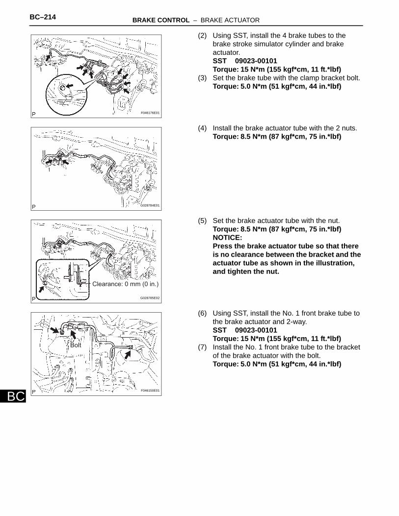
BC–214 BRAKE CONTROL – BRAKE ACTUATOR
BC
(2) Using SST, install the 4 brake tubes to the brake stroke simulator cylinder and brake actuator.SST 09023-00101Torque: 15 N*m (155 kgf*cm, 11 ft.*lbf)
(3) Set the brake tube with the clamp bracket bolt.Torque: 5.0 N*m (51 kgf*cm, 44 in.*lbf)
(4) Install the brake actuator tube with the 2 nuts.Torque: 8.5 N*m (87 kgf*cm, 75 in.*lbf)
(5) Set the brake actuator tube with the nut.Torque: 8.5 N*m (87 kgf*cm, 75 in.*lbf)NOTICE:Press the brake actuator tube so that there is no clearance between the bracket and the actuator tube as shown in the illustration, and tighten the nut.
(6) Using SST, install the No. 1 front brake tube to the brake actuator and 2-way.SST 09023-00101Torque: 15 N*m (155 kgf*cm, 11 ft.*lbf)
(7) Install the No. 1 front brake tube to the bracket of the brake actuator with the bolt.Torque: 5.0 N*m (51 kgf*cm, 44 in.*lbf)
F046176E01
G028784E01
Clearance: 0 mm (0 in.)
G028785E02
Bolt
F046150E01

BRAKE CONTROL – BRAKE ACTUATOR BC–215
C
B(8) Using SST, connect the No. 5 front brake tube.SST 09023-00101Torque: 15 N*m (155 kgf*cm, 11 ft.*lbf)
(9) Install the bracket of the No. 5 front brake tube with the bolt.Torque: 5.0 N*m (51 kgf*cm, 44 in.*lbf)
(10) Connect the brake actuator connector and fix it with the lock.
(11) Install the No. 2 brake actuator hose to the brake actuator with the clip.
(l) Connect the water pump with motor and bracket.(1) Install the heater hose bracket to the gusset
with the 2 clamps and bolt.
(2) Install the heater water pump with the 2 bolts.NOTICE:Tighten bolt A and then bolt B.
(3) Connect the heater water pump connector.(m) Install the inverter with converter (see page HV-
535).HINT:Refer to the procedures from the installation of the inverter with converter up until the installation of the engine under cover LH.
Bolt
F046174E01
G030217E01
F046172E01
A
B
F046171E02
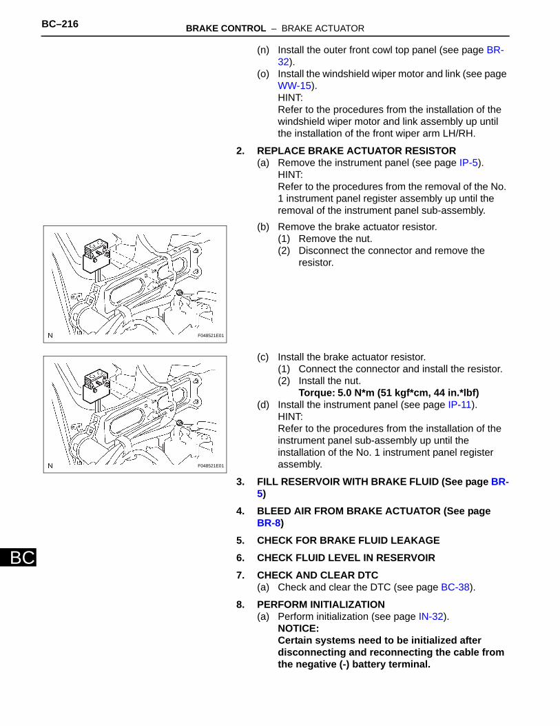
BC–216 BRAKE CONTROL – BRAKE ACTUATOR
BC
(n) Install the outer front cowl top panel (see page BR-32).
(o) Install the windshield wiper motor and link (see page WW-15).HINT:Refer to the procedures from the installation of the windshield wiper motor and link assembly up until the installation of the front wiper arm LH/RH.
2. REPLACE BRAKE ACTUATOR RESISTOR(a) Remove the instrument panel (see page IP-5).
HINT:Refer to the procedures from the removal of the No. 1 instrument panel register assembly up until the removal of the instrument panel sub-assembly.
(b) Remove the brake actuator resistor.(1) Remove the nut.(2) Disconnect the connector and remove the
resistor.
(c) Install the brake actuator resistor.(1) Connect the connector and install the resistor.(2) Install the nut.
Torque: 5.0 N*m (51 kgf*cm, 44 in.*lbf)(d) Install the instrument panel (see page IP-11).
HINT:Refer to the procedures from the installation of the instrument panel sub-assembly up until the installation of the No. 1 instrument panel register assembly.
3. FILL RESERVOIR WITH BRAKE FLUID (See page BR-5)
4. BLEED AIR FROM BRAKE ACTUATOR (See page BR-8)
5. CHECK FOR BRAKE FLUID LEAKAGE6. CHECK FLUID LEVEL IN RESERVOIR7. CHECK AND CLEAR DTC
(a) Check and clear the DTC (see page BC-38).
8. PERFORM INITIALIZATION(a) Perform initialization (see page IN-32).
NOTICE:Certain systems need to be initialized after disconnecting and reconnecting the cable from the negative (-) battery terminal.
F048521E01
F048521E01
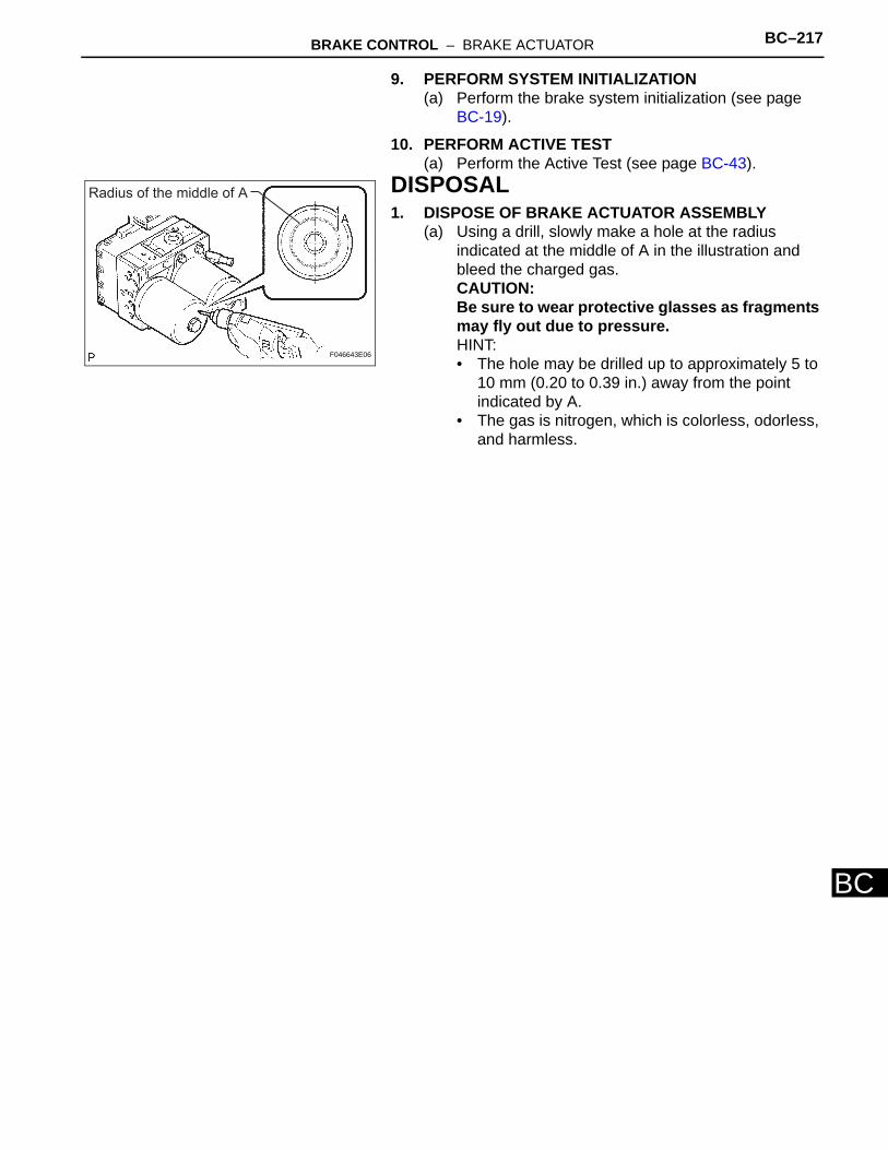
BRAKE CONTROL – BRAKE ACTUATOR BC–217
C
B9. PERFORM SYSTEM INITIALIZATION(a) Perform the brake system initialization (see page
BC-19).
10. PERFORM ACTIVE TEST(a) Perform the Active Test (see page BC-43).
DISPOSAL1. DISPOSE OF BRAKE ACTUATOR ASSEMBLY
(a) Using a drill, slowly make a hole at the radius indicated at the middle of A in the illustration and bleed the charged gas.CAUTION:Be sure to wear protective glasses as fragments may fly out due to pressure.HINT:• The hole may be drilled up to approximately 5 to
10 mm (0.20 to 0.39 in.) away from the point indicated by A.
• The gas is nitrogen, which is colorless, odorless, and harmless.
Radius of the middle of A
F046643E06
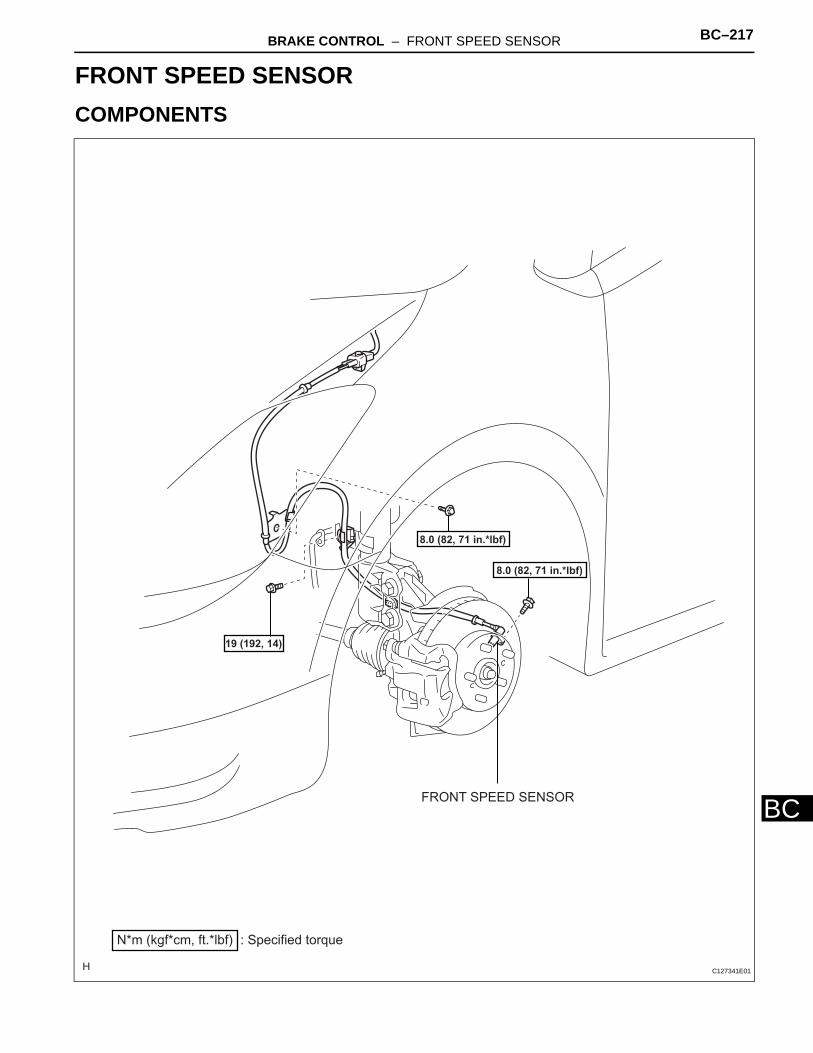
BRAKE CONTROL – FRONT SPEED SENSOR BC–217
BC
BRAKEBRAKE CONTROLFRONT SPEED SENSORCOMPONENTS
FRONT SPEED SENSOR
: Specified torqueN*m (kgf*cm, ft.*lbf)
19 (192, 14)
8.0 (82, 71 in.*lbf)
8.0 (82, 71 in.*lbf)
C127341E01
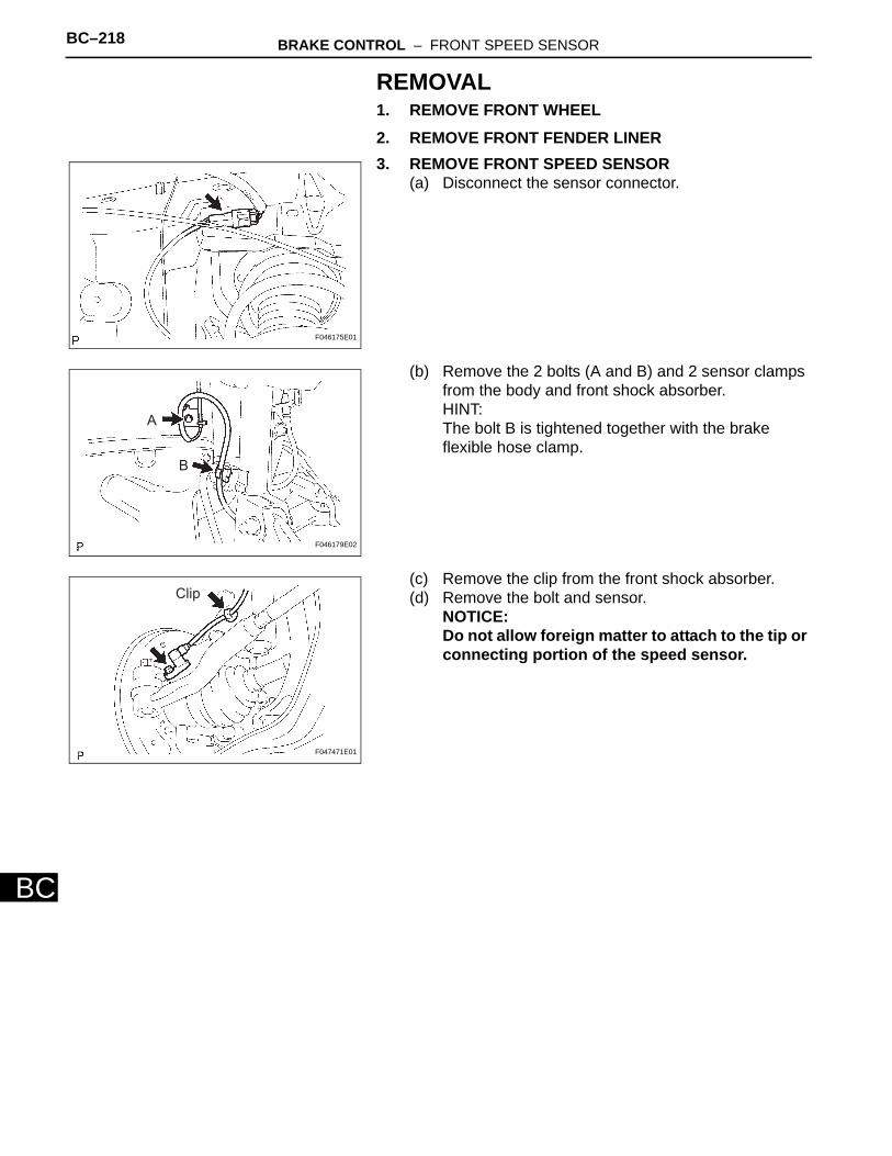
BC–218 BRAKE CONTROL – FRONT SPEED SENSOR
BC
REMOVAL1. REMOVE FRONT WHEEL2. REMOVE FRONT FENDER LINER3. REMOVE FRONT SPEED SENSOR
(a) Disconnect the sensor connector.
(b) Remove the 2 bolts (A and B) and 2 sensor clamps from the body and front shock absorber.HINT:The bolt B is tightened together with the brake flexible hose clamp.
(c) Remove the clip from the front shock absorber.(d) Remove the bolt and sensor.
NOTICE:Do not allow foreign matter to attach to the tip or connecting portion of the speed sensor.
F046175E01
A
B
F046179E02
Clip
F047471E01
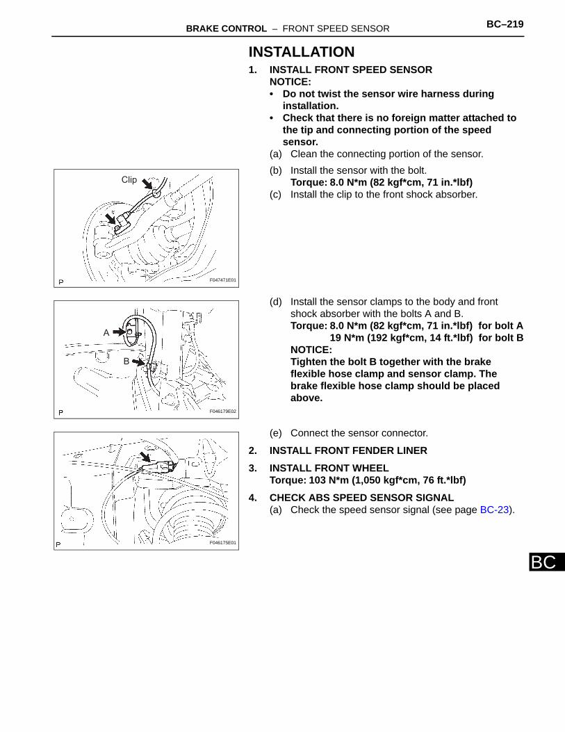
BRAKE CONTROL – FRONT SPEED SENSOR BC–219
BC
INSTALLATION1. INSTALL FRONT SPEED SENSOR
NOTICE:• Do not twist the sensor wire harness during
installation.• Check that there is no foreign matter attached to
the tip and connecting portion of the speed sensor.
(a) Clean the connecting portion of the sensor.(b) Install the sensor with the bolt.
Torque: 8.0 N*m (82 kgf*cm, 71 in.*lbf)(c) Install the clip to the front shock absorber.
(d) Install the sensor clamps to the body and front shock absorber with the bolts A and B.Torque: 8.0 N*m (82 kgf*cm, 71 in.*lbf) for bolt A
19 N*m (192 kgf*cm, 14 ft.*lbf) for bolt BNOTICE:Tighten the bolt B together with the brake flexible hose clamp and sensor clamp. The brake flexible hose clamp should be placed above.
(e) Connect the sensor connector.
2. INSTALL FRONT FENDER LINER3. INSTALL FRONT WHEEL
Torque: 103 N*m (1,050 kgf*cm, 76 ft.*lbf)4. CHECK ABS SPEED SENSOR SIGNAL
(a) Check the speed sensor signal (see page BC-23).
Clip
F047471E01
A
B
F046179E02
F046175E01
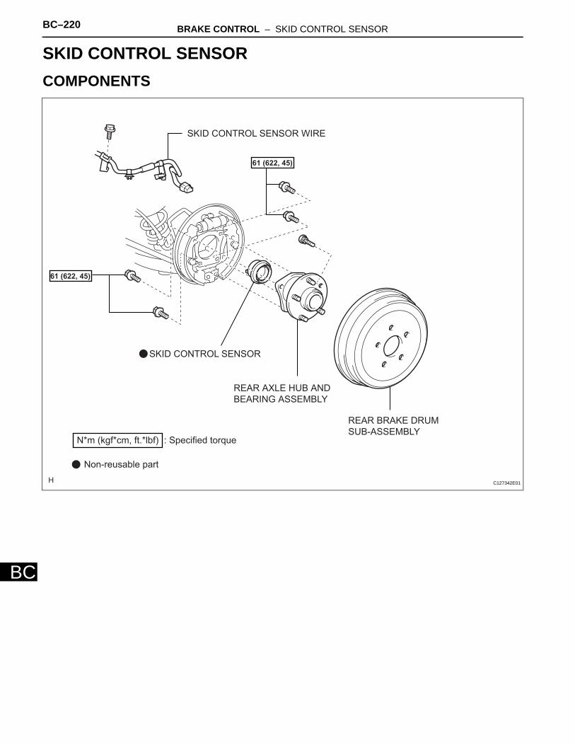
BC–220 BRAKE CONTROL – SKID CONTROL SENSOR
BC
BRAKEBRAKE CONTROLSKID CONTROL SENSORCOMPONENTS
REAR AXLE HUB AND
BEARING ASSEMBLY
REAR BRAKE DRUM
SUB-ASSEMBLY
SKID CONTROL SENSOR
SKID CONTROL SENSOR WIRE
: Specified torqueN*m (kgf*cm, ft.*lbf)
61 (622, 45)
61 (622, 45)
Non-reusable part
C127342E01
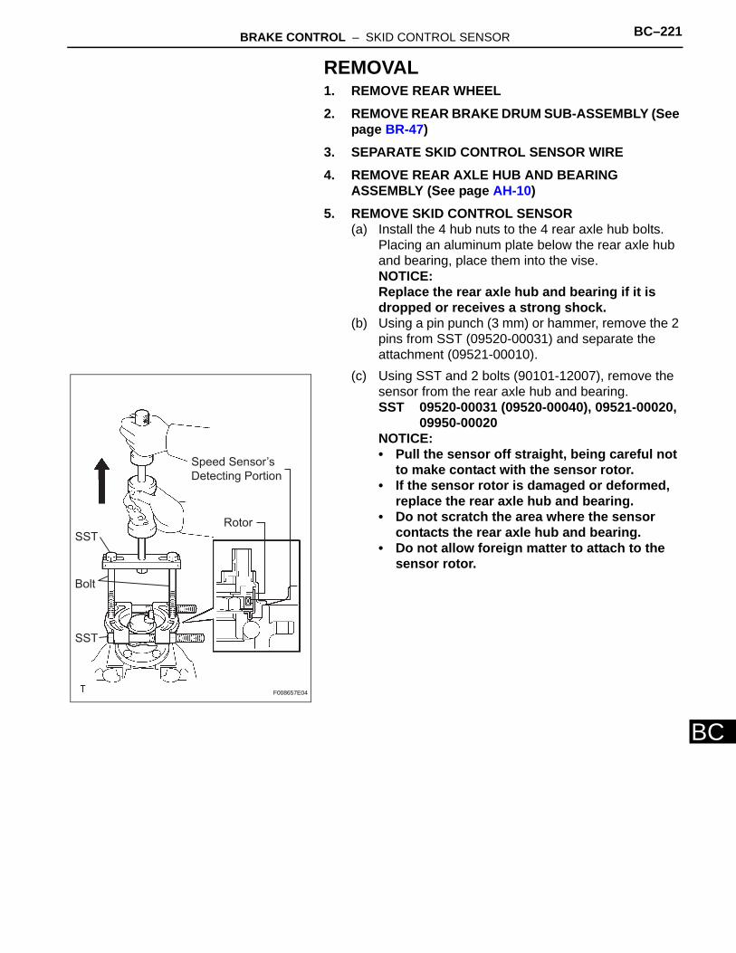
BRAKE CONTROL – SKID CONTROL SENSOR BC–221
BC
REMOVAL1. REMOVE REAR WHEEL2. REMOVE REAR BRAKE DRUM SUB-ASSEMBLY (See
page BR-47)3. SEPARATE SKID CONTROL SENSOR WIRE4. REMOVE REAR AXLE HUB AND BEARING
ASSEMBLY (See page AH-10)5. REMOVE SKID CONTROL SENSOR
(a) Install the 4 hub nuts to the 4 rear axle hub bolts. Placing an aluminum plate below the rear axle hub and bearing, place them into the vise.NOTICE:Replace the rear axle hub and bearing if it is dropped or receives a strong shock.
(b) Using a pin punch (3 mm) or hammer, remove the 2 pins from SST (09520-00031) and separate the attachment (09521-00010).
(c) Using SST and 2 bolts (90101-12007), remove the sensor from the rear axle hub and bearing.SST 09520-00031 (09520-00040), 09521-00020,
09950-00020NOTICE:• Pull the sensor off straight, being careful not
to make contact with the sensor rotor.• If the sensor rotor is damaged or deformed,
replace the rear axle hub and bearing.• Do not scratch the area where the sensor
contacts the rear axle hub and bearing.• Do not allow foreign matter to attach to the
sensor rotor.
SST
Bolt
Rotor
SST
Speed Sensor’s
Detecting Portion
F008657E04
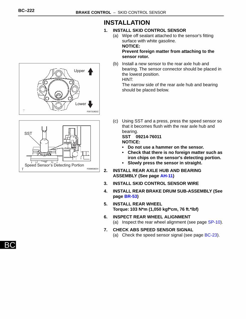
BC–222 BRAKE CONTROL – SKID CONTROL SENSOR
BC
INSTALLATION1. INSTALL SKID CONTROL SENSOR
(a) Wipe off sealant attached to the sensor's fitting surface with white gasoline.NOTICE:Prevent foreign matter from attaching to the sensor rotor.
(b) Install a new sensor to the rear axle hub and bearing. The sensor connector should be placed in the lowest position.HINT:The narrow side of the rear axle hub and bearing should be placed below.
(c) Using SST and a press, press the speed sensor so that it becomes flush with the rear axle hub and bearing.SST 09214-76011NOTICE:• Do not use a hammer on the sensor.• Check that there is no foreign matter such as
iron chips on the sensor's detecting portion.• Slowly press the sensor in straight.
2. INSTALL REAR AXLE HUB AND BEARING ASSEMBLY (See page AH-11)
3. INSTALL SKID CONTROL SENSOR WIRE4. INSTALL REAR BRAKE DRUM SUB-ASSEMBLY (See
page BR-53)5. INSTALL REAR WHEEL
Torque: 103 N*m (1,050 kgf*cm, 76 ft.*lbf)6. INSPECT REAR WHEEL ALIGNMENT
(a) Inspect the rear wheel alignment (see page SP-10).
7. CHECK ABS SPEED SENSOR SIGNAL(a) Check the speed sensor signal (see page BC-23).
Upper
Lower
F007318E02
SST
Speed Sensor’s Detecting PortionF008658E04
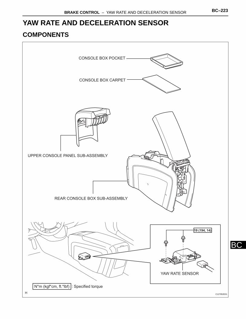
BRAKE CONTROL – YAW RATE AND DECELERATION SENSOR BC–223
BC
BRAKEBRAKE CONTROLYAW RATE AND DECELERATION SENSORCOMPONENTS
CONSOLE BOX CARPET
CONSOLE BOX POCKET
UPPER CONSOLE PANEL SUB-ASSEMBLY
YAW RATE SENSOR
: Specified torqueN*m (kgf*cm, ft.*lbf)
19 (194, 14)
REAR CONSOLE BOX SUB-ASSEMBLY
C127952E01
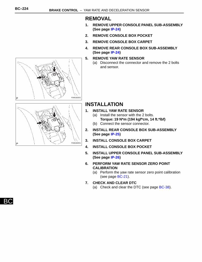
BC–224 BRAKE CONTROL – YAW RATE AND DECELERATION SENSOR
BC
REMOVAL1. REMOVE UPPER CONSOLE PANEL SUB-ASSEMBLY
(See page IP-24)2. REMOVE CONSOLE BOX POCKET3. REMOVE CONSOLE BOX CARPET4. REMOVE REAR CONSOLE BOX SUB-ASSEMBLY
(See page IP-24)5. REMOVE YAW RATE SENSOR
(a) Disconnect the connector and remove the 2 bolts and sensor.
INSTALLATION1. INSTALL YAW RATE SENSOR
(a) Install the sensor with the 2 bolts.Torque: 19 N*m (194 kgf*cm, 14 ft.*lbf)
(b) Connect the sensor connector.
2. INSTALL REAR CONSOLE BOX SUB-ASSEMBLY (See page IP-25)
3. INSTALL CONSOLE BOX CARPET4. INSTALL CONSOLE BOX POCKET5. INSTALL UPPER CONSOLE PANEL SUB-ASSEMBLY
(See page IP-26)6. PERFORM YAW RATE SENSOR ZERO POINT
CALIBRATION(a) Perform the yaw rate sensor zero point calibration
(see page BC-21).
7. CHECK AND CLEAR DTC(a) Check and clear the DTC (see page BC-38).
F046182E01
F046182E01
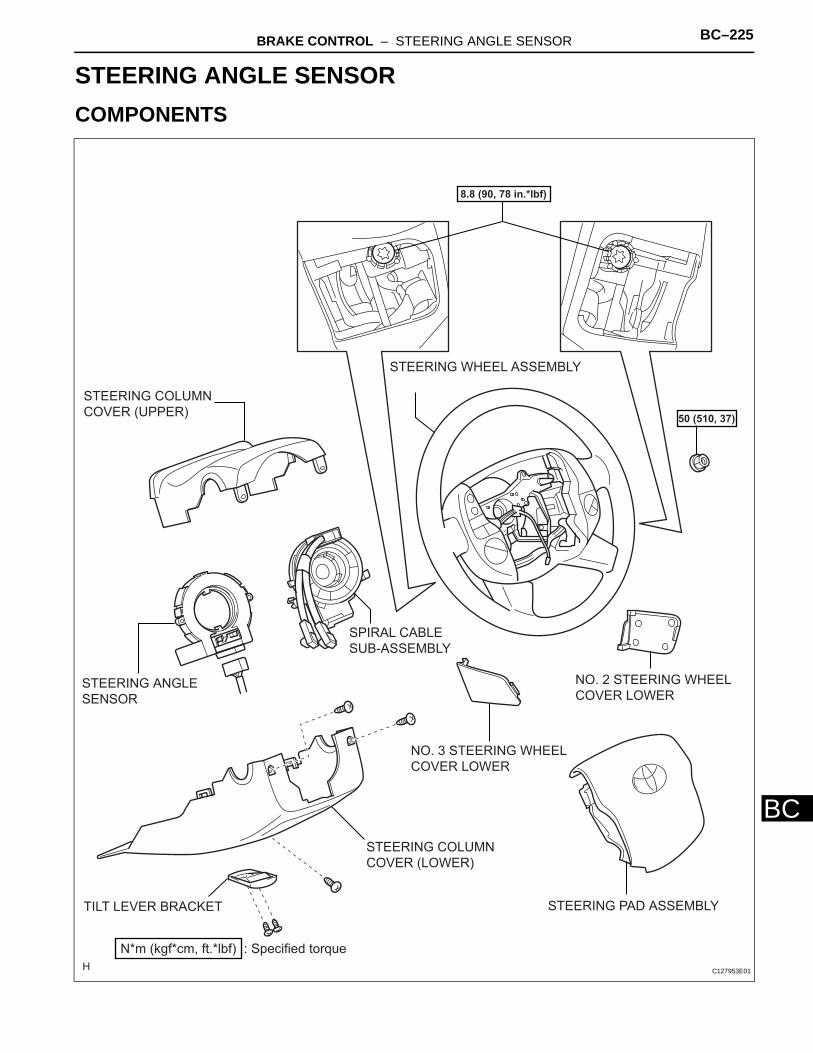
BRAKE CONTROL – STEERING ANGLE SENSOR BC–225
BC
BRAKEBRAKE CONTROLSTEERING ANGLE SENSORCOMPONENTS
NO. 2 STEERING WHEEL
COVER LOWER
NO. 3 STEERING WHEEL
COVER LOWER
SPIRAL CABLE
SUB-ASSEMBLY
STEERING COLUMN
COVER (UPPER)
STEERING WHEEL ASSEMBLY
TILT LEVER BRACKET
STEERING COLUMN
COVER (LOWER)
: Specified torqueN*m (kgf*cm, ft.*lbf)
50 (510, 37)
8.8 (90, 78 in.*lbf)
STEERING ANGLE
SENSOR
STEERING PAD ASSEMBLY
C127953E01
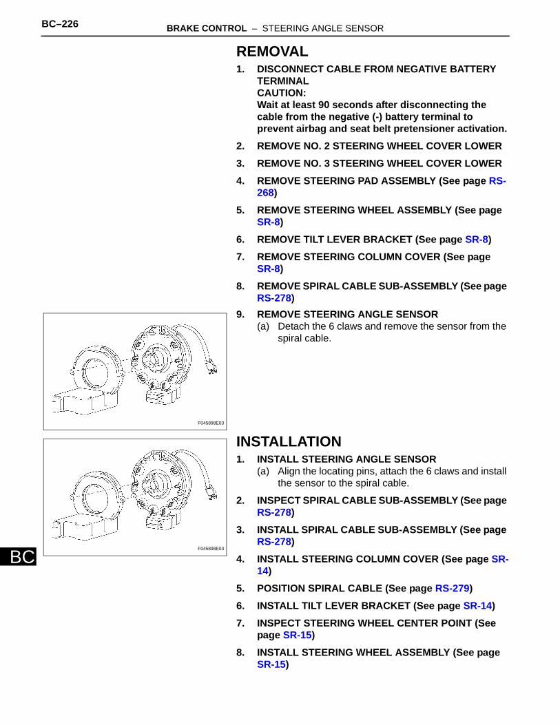
BC–226 BRAKE CONTROL – STEERING ANGLE SENSOR
BC
REMOVAL1. DISCONNECT CABLE FROM NEGATIVE BATTERY
TERMINALCAUTION:Wait at least 90 seconds after disconnecting the cable from the negative (-) battery terminal to prevent airbag and seat belt pretensioner activation.
2. REMOVE NO. 2 STEERING WHEEL COVER LOWER3. REMOVE NO. 3 STEERING WHEEL COVER LOWER4. REMOVE STEERING PAD ASSEMBLY (See page RS-
268)5. REMOVE STEERING WHEEL ASSEMBLY (See page
SR-8)6. REMOVE TILT LEVER BRACKET (See page SR-8)7. REMOVE STEERING COLUMN COVER (See page
SR-8)8. REMOVE SPIRAL CABLE SUB-ASSEMBLY (See page
RS-278)9. REMOVE STEERING ANGLE SENSOR
(a) Detach the 6 claws and remove the sensor from the spiral cable.
INSTALLATION1. INSTALL STEERING ANGLE SENSOR
(a) Align the locating pins, attach the 6 claws and install the sensor to the spiral cable.
2. INSPECT SPIRAL CABLE SUB-ASSEMBLY (See page RS-278)
3. INSTALL SPIRAL CABLE SUB-ASSEMBLY (See page RS-278)
4. INSTALL STEERING COLUMN COVER (See page SR-14)
5. POSITION SPIRAL CABLE (See page RS-279)6. INSTALL TILT LEVER BRACKET (See page SR-14)7. INSPECT STEERING WHEEL CENTER POINT (See
page SR-15)8. INSTALL STEERING WHEEL ASSEMBLY (See page
SR-15)
F045898E03
F045898E03
BRAKE CONTROL – STEERING ANGLE SENSOR BC–227
BC
9. INSTALL STEERING PAD ASSEMBLY (See page RS-269)
10. INSPECT STEERING PAD ASSEMBLY(a) Inspect the steering pad (see page RS-267).
11. CONNECT CABLE TO NEGATIVE BATTERY TERMINAL
12. PERFORM INITIALIZATION(a) Perform initialization (see page IN-32).
NOTICE:Certain systems need to be initialized after disconnecting and reconnecting the cable from the negative (-) battery terminal.
13. CHECK SRS WARNING LIGHT(a) Check the SRS warning light (see page RS-41).
BC–228 BRAKE CONTROL – SKID CONTROL ECU
BC
BRAKEBRAKE CONTROLSKID CONTROL ECUCOMPONENTS
: Specified torqueN*m (kgf*cm, ft.*lbf)
5.0 (51, 44 in.*lbf)
5.0 (51, 44 in.*lbf)
SKID CONTROL ECU
C127345E01
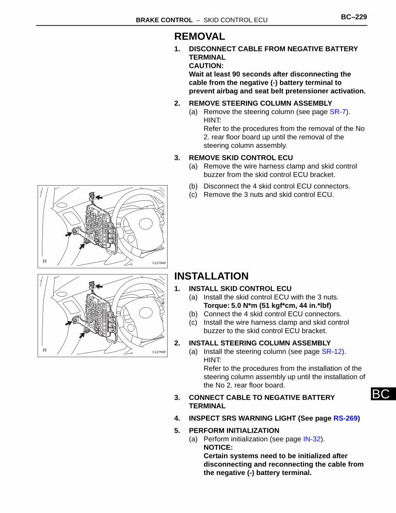
BRAKE CONTROL – SKID CONTROL ECU BC–229
BC
REMOVAL1. DISCONNECT CABLE FROM NEGATIVE BATTERY
TERMINALCAUTION:Wait at least 90 seconds after disconnecting the cable from the negative (-) battery terminal to prevent airbag and seat belt pretensioner activation.
2. REMOVE STEERING COLUMN ASSEMBLY(a) Remove the steering column (see page SR-7).
HINT:Refer to the procedures from the removal of the No 2. rear floor board up until the removal of the steering column assembly.
3. REMOVE SKID CONTROL ECU(a) Remove the wire harness clamp and skid control
buzzer from the skid control ECU bracket.(b) Disconnect the 4 skid control ECU connectors.(c) Remove the 3 nuts and skid control ECU.
INSTALLATION1. INSTALL SKID CONTROL ECU
(a) Install the skid control ECU with the 3 nuts.Torque: 5.0 N*m (51 kgf*cm, 44 in.*lbf)
(b) Connect the 4 skid control ECU connectors.(c) Install the wire harness clamp and skid control
buzzer to the skid control ECU bracket.
2. INSTALL STEERING COLUMN ASSEMBLY(a) Install the steering column (see page SR-12).
HINT:Refer to the procedures from the installation of the steering column assembly up until the installation of the No 2. rear floor board.
3. CONNECT CABLE TO NEGATIVE BATTERY TERMINAL
4. INSPECT SRS WARNING LIGHT (See page RS-269)5. PERFORM INITIALIZATION
(a) Perform initialization (see page IN-32).NOTICE:Certain systems need to be initialized after disconnecting and reconnecting the cable from the negative (-) battery terminal.
C127949
C127949
BC–230 BRAKE CONTROL – SKID CONTROL ECU
BC
6. PERFORM SYSTEM INITIALIZATION(a) Perform the brake system initialization (see page
BC-19).
7. PERFORM YAW RATE SENSOR ZERO POINT CALIBRATION(a) Perform the yaw rate sensor zero point calibration
(see page BC-21).
8. CHECK AND CLEAR DTC(a) Check and clear the DTCs (see page BC-38).
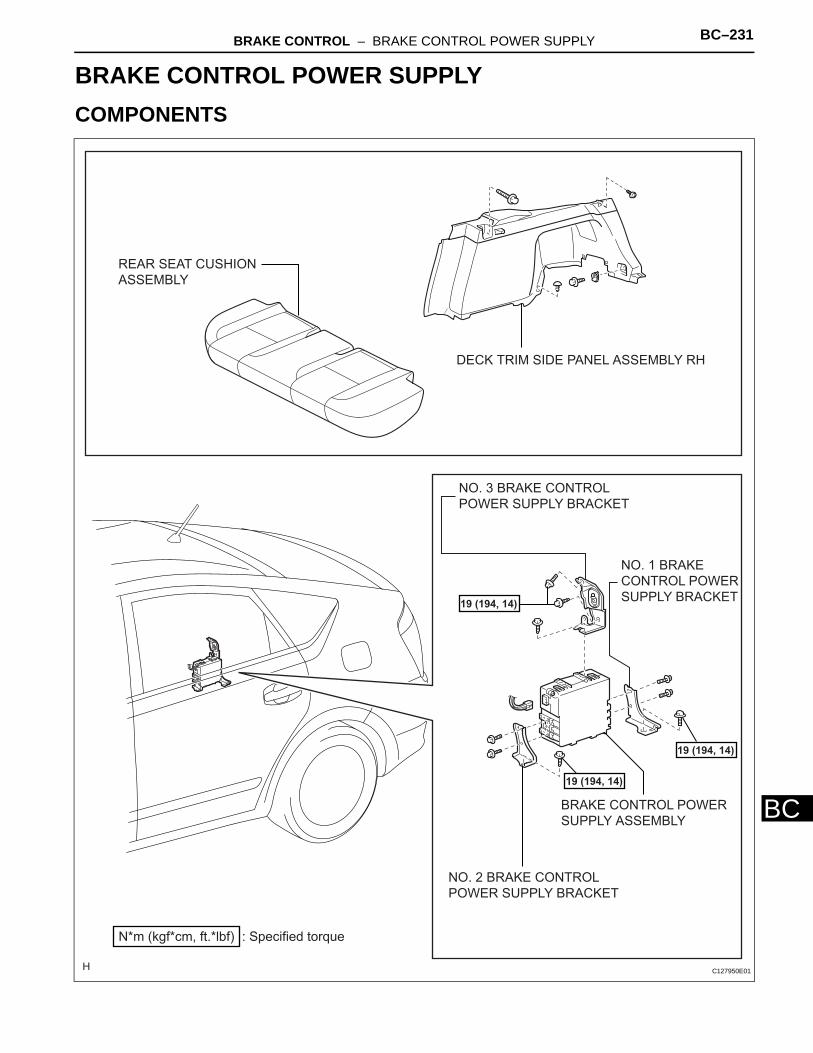
BRAKE CONTROL – BRAKE CONTROL POWER SUPPLY BC–231
BC
BRAKEBRAKE CONTROLBRAKE CONTROL POWER SUPPLYCOMPONENTS
BRAKE CONTROL POWER
SUPPLY ASSEMBLY
DECK TRIM SIDE PANEL ASSEMBLY RH
NO. 1 BRAKE
CONTROL POWER
SUPPLY BRACKET
NO. 2 BRAKE CONTROL
POWER SUPPLY BRACKET
NO. 3 BRAKE CONTROL
POWER SUPPLY BRACKET
REAR SEAT CUSHION
ASSEMBLY
: Specified torqueN*m (kgf*cm, ft.*lbf)
19 (194, 14)
19 (194, 14)
19 (194, 14)
C127950E01
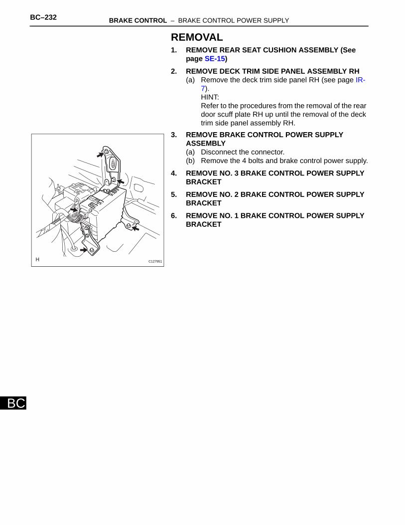
BC–232 BRAKE CONTROL – BRAKE CONTROL POWER SUPPLY
BC
REMOVAL1. REMOVE REAR SEAT CUSHION ASSEMBLY (See
page SE-15)2. REMOVE DECK TRIM SIDE PANEL ASSEMBLY RH
(a) Remove the deck trim side panel RH (see page IR-7).HINT:Refer to the procedures from the removal of the rear door scuff plate RH up until the removal of the deck trim side panel assembly RH.
3. REMOVE BRAKE CONTROL POWER SUPPLY ASSEMBLY(a) Disconnect the connector.(b) Remove the 4 bolts and brake control power supply.
4. REMOVE NO. 3 BRAKE CONTROL POWER SUPPLY BRACKET
5. REMOVE NO. 2 BRAKE CONTROL POWER SUPPLY BRACKET
6. REMOVE NO. 1 BRAKE CONTROL POWER SUPPLY BRACKET
C127951
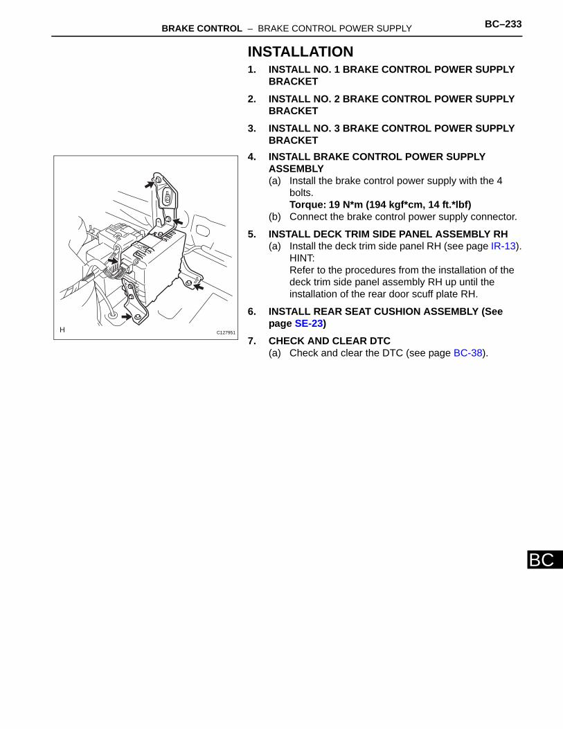
BRAKE CONTROL – BRAKE CONTROL POWER SUPPLY BC–233
BC
INSTALLATION1. INSTALL NO. 1 BRAKE CONTROL POWER SUPPLY
BRACKET2. INSTALL NO. 2 BRAKE CONTROL POWER SUPPLY
BRACKET3. INSTALL NO. 3 BRAKE CONTROL POWER SUPPLY
BRACKET4. INSTALL BRAKE CONTROL POWER SUPPLY
ASSEMBLY(a) Install the brake control power supply with the 4
bolts.Torque: 19 N*m (194 kgf*cm, 14 ft.*lbf)
(b) Connect the brake control power supply connector.
5. INSTALL DECK TRIM SIDE PANEL ASSEMBLY RH(a) Install the deck trim side panel RH (see page IR-13).
HINT:Refer to the procedures from the installation of the deck trim side panel assembly RH up until the installation of the rear door scuff plate RH.
6. INSTALL REAR SEAT CUSHION ASSEMBLY (See page SE-23)
7. CHECK AND CLEAR DTC(a) Check and clear the DTC (see page BC-38).
C127951
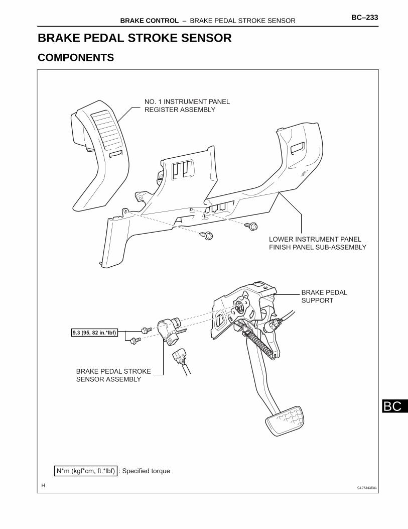
BRAKE CONTROL – BRAKE PEDAL STROKE SENSOR BC–233
BC
BRAKEBRAKE CONTROLBRAKE PEDAL STROKE SENSORCOMPONENTS
BRAKE PEDAL STROKE
SENSOR ASSEMBLY
LOWER INSTRUMENT PANEL
FINISH PANEL SUB-ASSEMBLY
NO. 1 INSTRUMENT PANEL
REGISTER ASSEMBLY
: Specified torqueN*m (kgf*cm, ft.*lbf)
9.3 (95, 82 in.*lbf)
BRAKE PEDAL
SUPPORT
C127343E01
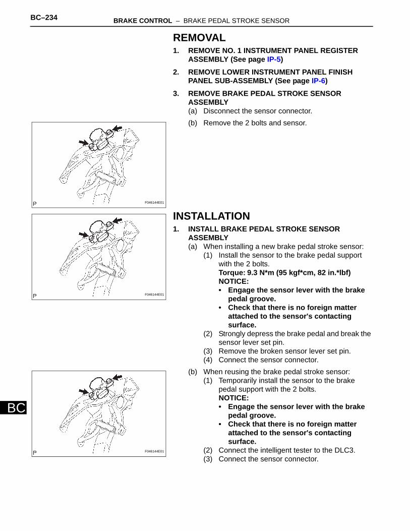
BC–234 BRAKE CONTROL – BRAKE PEDAL STROKE SENSOR
BC
REMOVAL1. REMOVE NO. 1 INSTRUMENT PANEL REGISTER
ASSEMBLY (See page IP-5)2. REMOVE LOWER INSTRUMENT PANEL FINISH
PANEL SUB-ASSEMBLY (See page IP-6)3. REMOVE BRAKE PEDAL STROKE SENSOR
ASSEMBLY(a) Disconnect the sensor connector.(b) Remove the 2 bolts and sensor.
INSTALLATION1. INSTALL BRAKE PEDAL STROKE SENSOR
ASSEMBLY(a) When installing a new brake pedal stroke sensor:
(1) Install the sensor to the brake pedal support with the 2 bolts.Torque: 9.3 N*m (95 kgf*cm, 82 in.*lbf)NOTICE:• Engage the sensor lever with the brake
pedal groove.• Check that there is no foreign matter
attached to the sensor's contacting surface.
(2) Strongly depress the brake pedal and break the sensor lever set pin.
(3) Remove the broken sensor lever set pin.(4) Connect the sensor connector.
(b) When reusing the brake pedal stroke sensor:(1) Temporarily install the sensor to the brake
pedal support with the 2 bolts.NOTICE:• Engage the sensor lever with the brake
pedal groove.• Check that there is no foreign matter
attached to the sensor's contacting surface.
(2) Connect the intelligent tester to the DLC3.(3) Connect the sensor connector.
F046144E01
F046144E01
F046144E01
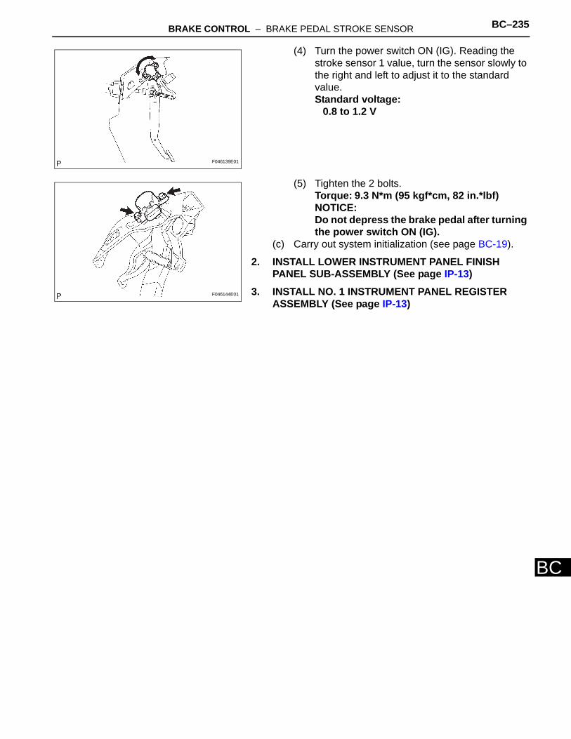
BRAKE CONTROL – BRAKE PEDAL STROKE SENSOR BC–235
BC
(4) Turn the power switch ON (IG). Reading the stroke sensor 1 value, turn the sensor slowly to the right and left to adjust it to the standard value.Standard voltage:
0.8 to 1.2 V
(5) Tighten the 2 bolts.Torque: 9.3 N*m (95 kgf*cm, 82 in.*lbf)NOTICE:Do not depress the brake pedal after turning the power switch ON (IG).
(c) Carry out system initialization (see page BC-19).
2. INSTALL LOWER INSTRUMENT PANEL FINISH PANEL SUB-ASSEMBLY (See page IP-13)
3. INSTALL NO. 1 INSTRUMENT PANEL REGISTER ASSEMBLY (See page IP-13)
F046139E01
F046144E01