Embed Size (px)
Citation preview

Universal Process Controller
C310
Installation GuideIM/C310–INS Issue 8
ABB
EN ISO 9001:2000
Cert. No. Q5907
The CompanyWe are an established world force in the design and manufacture ofinstrumentation for industrial process control, flow measurement, gas andliquid analysis and environmental applications.
As a part of ABB, a world leader in process automation technology, we offercustomers application expertise, service and support worldwide.
We are committed to teamwork, high quality manufacturing, advancedtechnology and unrivalled service and support.
The quality, accuracy and performance of the Company’s products resultfrom over 100 years experience, combined with a continuous program ofinnovative design and development to incorporate the latest technology.
The UKAS Calibration Laboratory No. 0255 is just one of the ten flowcalibration plants operated by the Company, and is indicative of ourdedication to quality and accuracy.
EN 29001 (ISO 9001)
Lenno, Italy – Cert. No. 9/90A
REGISTERE
D
Health and SafetyTo ensure that our products are safe and without risk to health, the following points must be noted:
1. The relevant sections of these instructions must be read carefully before proceeding.
2. Warning labels on containers and packages must be observed.
3. Installation, operation, maintenance and servicing must only be carried out by suitably trained personnel andin accordance with the information given.
4. Normal safety precautions must be taken to avoid the possibility of an accident occurring when operating inconditions of high pressure and/or temperature.
5. Chemicals must be stored away from heat, protected from temperature extremes and powders kept dry.Normal safe handling procedures must be used.
6. When disposing of chemicals ensure that no two chemicals are mixed.
Safety advice concerning the use of the equipment described in this manual or any relevant hazard data sheets(where applicable) may be obtained from the Company address on the back cover, together with servicing andspares information.
Electrical SafetyThis equipment complies with the requirements of CEI/IEC 61010-1:2001-2 "Safety requirements for electricalequipment for measurement, control, and laboratory use". If the equipment is used in a manner NOT specified by theCompany, the protection provided by the equipment may be impaired.
SymbolsOne or more of the following symbols may appear on the equipment labelling:
Information in this manual is intended only to assist our customers in the efficient operation of our equipment. Useof this manual for any other purpose is specifically prohibited and its contents are not to be reproduced in full or partwithout prior approval of the Technical Communications Department.
Warning – Refer to the manual for instructions
Caution – Risk of electric shock
Protective earth (ground) terminal
Earth (ground) terminal
Direct current supply only
Alternating current supply only
Both direct and alternating current supply
The equipment is protectedthrough double insulation
1
CONTENTS
1 INTRODUCTION .................................. 2
2 PREPARATION .................................... 32.1 Checking the Code Number ......... 3
3 MECHANICAL INSTALLATION .......... 43.1 Siting .......................................... 43.2 Mounting ...................................... 5
4 ELECTRICAL INSTALLATION ............ 64.1 Access to Terminals ..................... 64.2 Setting the Input Selector Links ... 64.3 Setting the Isolated Output Link ... 64.4 Cable Glands and
Conduit Fixings ............................ 84.4.1 Cable Glands
(IEC – 20mm) ................... 84.4.2 Conduit Adaptors
(N. American – 0.5in) ........ 84.4.3 Cable Glands
(N. American – 0.5in) ........ 94.5 Connections Summary ............... 104.6 Input Connections ...................... 12
4.6.1 Thermocouple(THC) Inputs ................... 12
4.6.2 3-lead ResistanceThermometer (RTD)Inputs .............................. 12
4.6.3 2-lead ResistanceThermometer (RTD)Inputs .............................. 12
4.6.4 Links for Unused Inputs .. 124.7 Output Connections ................... 144.8 Relay Connections ..................... 144.9 Motorized Valve Connections .... 144.10 Logic Input Connections ............ 154.11 Power Supply Selection and
AC Connections ......................... 16
5 INSTALLATION RECORD ................. 17
2
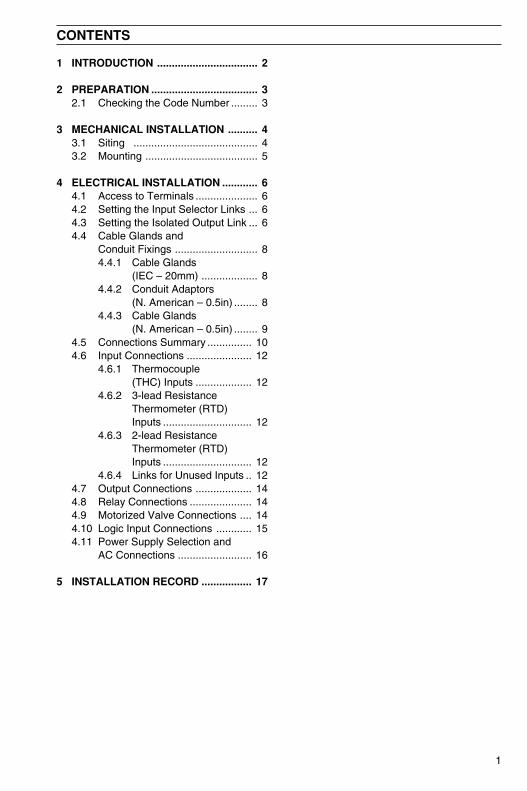
The COMMANDER 310 Series documentation is shown in Fig. 1.1. The Standard Manuals,including the specification sheet, are supplied with all instruments. The Modbus Supplement issupplied with instruments configured for Modbus Serial Communication.
This manual includes an Installation Record which should be completed as a log of the electricalinstallation. The record is useful when carrying out initial instrument programming and can beretained for future reference.
1 INTRODUCTION
PROGRAMMING
Part No.IM/C300–PG
Basic Config. Level
Advanced Config. Level
OPERATION
Setting Up
Displays & Controls
Operating Level
Simple Fault Finding
Part No.IM/C300–OG
Part No.IM/C310–INS
INSTALLATION
Product Identification
Siting
MountingElectrical Connections
Installation Record
MODBUS (RTU)
Serial Adaptors
Serial Connections
Programming Page
Modbus Registers
Part No.IM/C310–MOD
SPECIFICATION SHT.
Full Specification
Part No.SS C310
Standard Manuals Modbus Supplement
Fig. 1.1 Commander 310 Documentation
3
2 PREPARATION
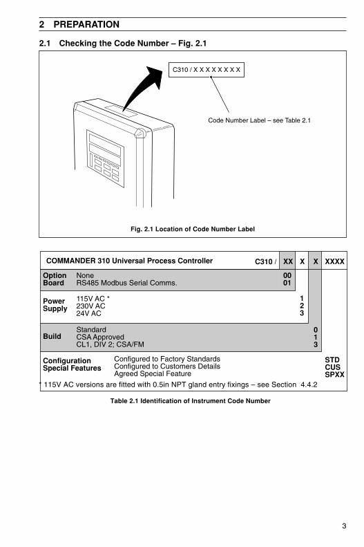
2.1 Checking the Code Number – Fig. 2.1
Fig. 2.1 Location of Code Number Label
COMMANDER 310 Universal Process Controller C310 /
NoneRS485 Modbus Serial Comms.
0001
115V AC *230V AC24V AC
123
013
StandardCSA ApprovedCL1, DIV 2; CSA/FM
Configured to Factory StandardsConfigured to Customers DetailsAgreed Special Feature
STDCUSSPXX
XXXXXXXX
OptionBoard
PowerSupply
Build
ConfigurationSpecial Features
Table 2.1 Identification of Instrument Code Number
* 115V AC versions are fitted with 0.5in NPT gland entry fixings – see Section 4.4.2
Code Number Label – see Table 2.1
C310 / X X X X X X X X

4
3 MECHANICAL INSTALLATION
EC Directive 89/336/EEC
In order to meet the requirements of theEC Directive 89/336/EEC for EMCregulations, this product must not be usedin a non-industrial environment.
3.1 Siting – Figs. 3.1 and 3.2 A – Within Temperature Limits
B – Within Humidity Limits
SensorMinimum
A – Close to Sensor
B – At Eye-level Location
Fig. 3.1 General Requirements
C – Avoid Vibration
55°CMax.
–10°CMin.
0 to 95% RH
+
IP66/NEMA4X
Caution. Select a location awayfrom strong electrical and magneticfields. If these cannot be avoided,particularly in applications where‘walkie talkies’ are used, connectusing screened cables withinearthed metal conduit.
D – Use Screened Cables
Fig. 3.2 Environmental Requirements
C – Within Protection Rating Limits
5
3 MECHANICAL INSTALLATION…
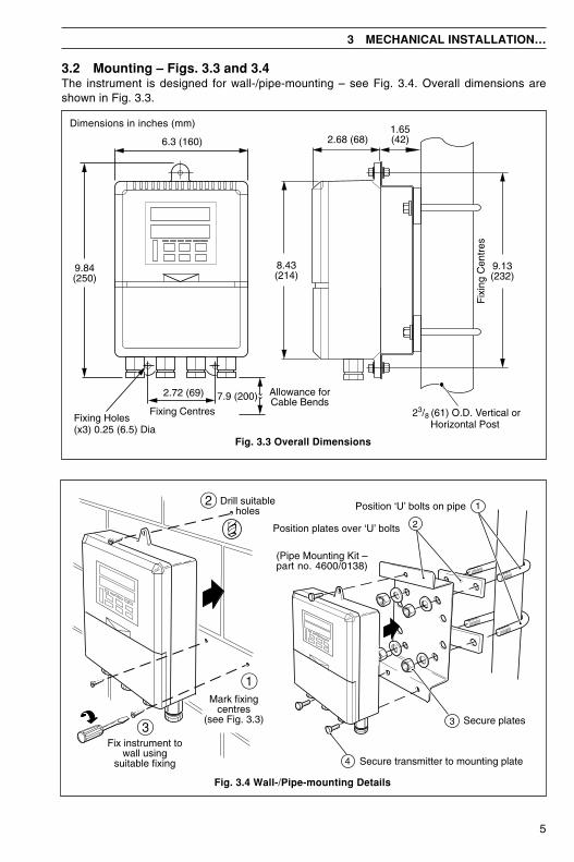
3.2 Mounting – Figs. 3.3 and 3.4The instrument is designed for wall-/pipe-mounting – see Fig. 3.4. Overall dimensions areshown in Fig. 3.3.
Dimensions in inches (mm)
2.68 (68)
8.43(214)
9.13(232)
Fix
ing
Cen
tres
6.3 (160)
9.84(250)
2.72 (69)
Fixing Centres
Allowance forCable Bends7.9 (200)
1.65(42)
23/8 (61) O.D. Vertical orHorizontal Post
Fixing Holes(x3) 0.25 (6.5) Dia
Fig. 3.3 Overall Dimensions
Fig. 3.4 Wall-/Pipe-mounting Details
Mark fixingcentres
(see Fig. 3.3)
1
2 Drill suitableholes
3Fix instrument to
wall usingsuitable fixing
Position ‘U’ bolts on pipe
Position plates over ‘U’ bolts
Secure transmitter to mounting plate
Secure plates
(Pipe Mounting Kit –part no. 4600/0138)
1
2
3
4
6
4 ELECTRICAL INSTALLATION
Warning. Before making anyconnections, ensure that the powersupply, any high voltage-operated controlcircuits and high common mode voltagesare switched off.
Note.• Always route signal leads and power
cables separately, preferably inearthed metal conduit.
• It is strongly recommended thatscreened cable is used for signalinputs and relay connections. Connectthe screen to the ground stud.
Information. Use cable appropriate forthe load currents. The terminals acceptcables up 12AWG (2.5mm2).
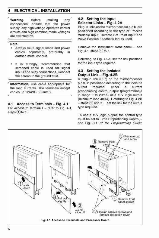
4.1 Access to Terminals – Fig. 4.1For access to terminals – refer to Fig. 4.1,steps 1 to 3.
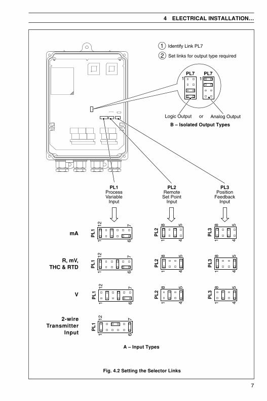
4.2 Setting the InputSelector Links – Fig. 4.2APlug-in links on the microprocessor p.c.b. arepositioned according to the type of ProcessVariable Input, Remote Set Point Input andValve Position Feedback Inputs used.
Remove the instrument front panel – seeFig. 4.1, steps 1 to 6.
Referring to Fig. 4.2A, set the link positionsfor the input type required.
4.3 Setting the IsolatedOutput Link – Fig. 4.2BA plug-in link (PL7) on the microprocessorp.c.b. is positioned according to the isolatedoutput required, either a currentproportioning control output (programmablein range 0 to 20mA) or a 12V logic output(minimum load 400Ω). Referring to Fig. 4.2B– steps 1 and 2, set the link for the outputtype required.
To use a 12V logic output, the control typemust be set to Time Proportioning Control –see Fig. 3.1 of the Programming Guide.
Fig. 4.1 Access to Terminals and Processor Board
Slacken captive screws andremove protection cover
Remove frontpanel screws
Remove frontpanel
Remove capand screw
4
6
slidedown
1
Pull outslightly…
…andslide off
2
2
5
3
7
4 ELECTRICAL INSTALLATION…
B – Isolated Output Types
Fig. 4.2 Setting the Selector Links
A – Input Types
PL3Position
FeedbackInput
PL2RemoteSet Point
Input
PL1ProcessVariable
Input
PL
2
PL
11 6
12 7
1 4
8 5
PL
1
PL
2
1 6
12 7
1 4
8 5
PL
1
PL
2
1 6
12 7
1 4
8 5
2-wireTransmitter
Input 1 6
12 7
PL
1
1
2
Identify Link PL7
Set links for output type required
mA PL
31 4
8 5
R, mV,THC & RTD P
L3
1 4
8 5
V PL
31 4
8 5
Analog OutputLogic Output or
PL71
PL71
8
…4 ELECTRICAL INSTALLATION
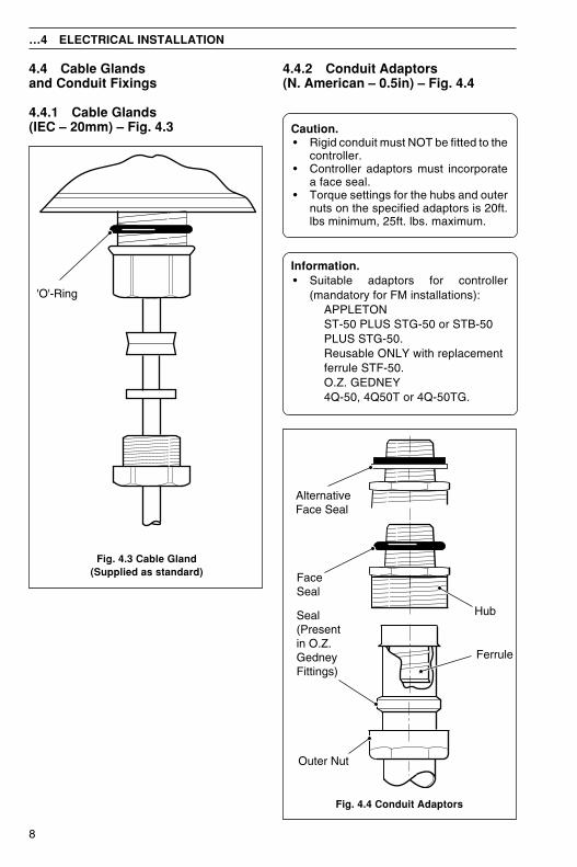
4.4 Cable Glandsand Conduit Fixings
4.4.1 Cable Glands(IEC – 20mm) – Fig. 4.3
4.4.2 Conduit Adaptors(N. American – 0.5in) – Fig. 4.4
Caution.• Rigid conduit must NOT be fitted to the
controller.• Controller adaptors must incorporate
a face seal.• Torque settings for the hubs and outer
nuts on the specified adaptors is 20ft.lbs minimum, 25ft. lbs. maximum.
Information.• Suitable adaptors for controller
(mandatory for FM installations):APPLETONST-50 PLUS STG-50 or STB-50PLUS STG-50.Reusable ONLY with replacementferrule STF-50.O.Z. GEDNEY4Q-50, 4Q50T or 4Q-50TG.
Fig. 4.4 Conduit Adaptors
'O'-Ring
Fig. 4.3 Cable Gland(Supplied as standard)
Ferrule
Outer Nut
Seal(Presentin O.Z.GedneyFittings)
AlternativeFace Seal
FaceSeal
Hub
9
4 ELECTRICAL INSTALLATION…
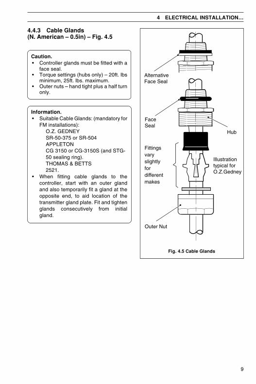
Fig. 4.5 Cable Glands
4.4.3 Cable Glands(N. American – 0.5in) – Fig. 4.5
Caution.• Controller glands must be fitted with a
face seal.• Torque settings (hubs only) – 20ft. lbs
minimum, 25ft. lbs. maximum.• Outer nuts – hand tight plus a half turn
only.
Information.• Suitable Cable Glands: (mandatory for
FM installations):O.Z. GEDNEYSR-50-375 or SR-504APPLETONCG 3150 or CG-3150S (and STG-50 sealing ring).THOMAS & BETTS2521.
• When fitting cable glands to thecontroller, start with an outer glandand also temporarily fit a gland at theopposite end, to aid location of thetransmitter gland plate. Fit and tightenglands consecutively from initialgland.
Fittingsvaryslightlyfordifferentmakes
Outer Nut
AlternativeFace Seal
FaceSeal
Hub
Illustrationtypical forO.Z.Gedney
10
…4 ELECTRICAL INSTALLATION
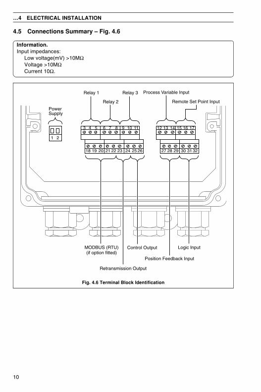
Fig. 4.6 Terminal Block Identification
4.5 Connections Summary – Fig. 4.6
Information.Input impedances:
Low voltage(mV) >10MΩVoltage >10MΩCurrent 10Ω.
3 4 5 6 7 8 9
18 19 20 21 22 23 24 25 26 27 28 29 30 31 32
10 11 12 13 14 15
1 2
16 17
PowerSupply
Relay 1
Relay 2
Relay 3
MODBUS (RTU)(if option fitted)
Retransmission Output
Position Feedback Input
Process Variable Input
Remote Set Point Input
Logic InputControl Output
11
4 ELECTRICAL INSTALLATION…
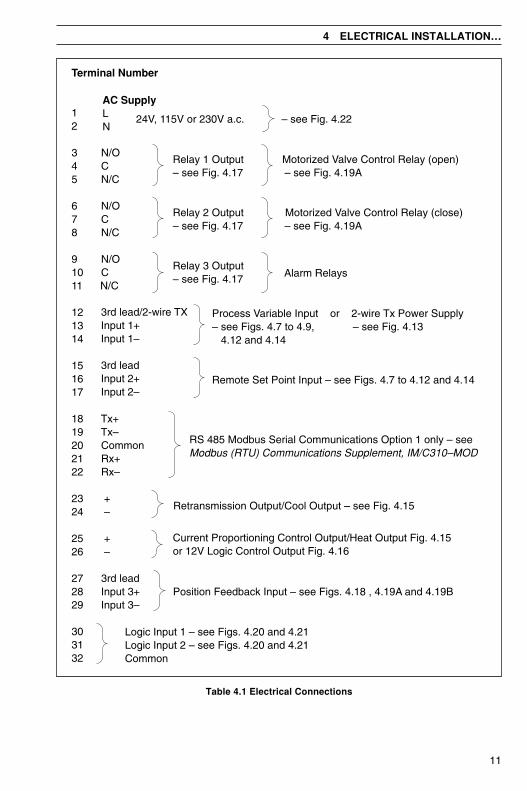
Table 4.1 Electrical Connections
Terminal Number
12
3 N/O4 C5 N/C
6 N/O7 C8 N/C
9 N/O10 C11 N/C
121314
151617
18 Tx+19 Tx–20 Common21 Rx+22 Rx–
23 +24 –
25 +26 –
27 3rd lead28 Input 3+29 Input 3–
303132
3rd lead/2-wire TXInput 1+Input 1–
3rd leadInput 2+Input 2–
Retransmission Output/Cool Output – see Fig. 4.15
Process Variable Input or 2-wire Tx Power Supply– see Figs. 4.7 to 4.9, – see Fig. 4.13 4.12 and 4.14
Remote Set Point Input – see Figs. 4.7 to 4.12 and 4.14
Relay 1 Output Motorized Valve Control Relay (open)– see Fig. 4.17 – see Fig. 4.19A
Relay 2 Output Motorized Valve Control Relay (close)– see Fig. 4.17 – see Fig. 4.19A
Relay 3 Output– see Fig. 4.17
AC SupplyLN
– see Fig. 4.22
Alarm Relays
Position Feedback Input – see Figs. 4.18 , 4.19A and 4.19B
Logic Input 1 – see Figs. 4.20 and 4.21Logic Input 2 – see Figs. 4.20 and 4.21Common
RS 485 Modbus Serial Communications Option 1 only – seeModbus (RTU) Communications Supplement, IM/C310–MOD
Current Proportioning Control Output/Heat Output Fig. 4.15or 12V Logic Control Output Fig. 4.16
24V, 115V or 230V a.c.

12
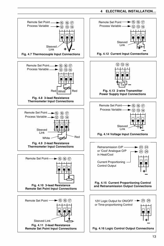
4.6 Input ConnectionsMake connections to each input, as shown in Figs 4.4 to 4.14, first removing any factory-fittedwire links not required.
4.6.1 Thermocouple (THC) Inputs – Fig. 4.7
Note. Automatic Cold Junction Compensation (ACJC) is active when an input isprogrammed for use with thermocouples. Use the correct compensating cable between theTHC and the terminals – see Table 4.2.If an external fixed cold junction is used, the connections to the instrument must be madewith copper cable. The input must be programmed for mV input signals and the appropriateTHC linearizer selected – see Sections 4.5 and 4.6 of the Programming Guide.
Table 4.2 Thermocouple Compensating Cables
4.6.2 3-lead Resistance Thermometer (RTD) Inputs – Fig. 4.8The three leads must have equal resistance, not exceeding 50Ω each.
4.6.3 2-lead Resistance Thermometer (RTD) Inputs – Fig. 4.9If long leads are necessary it is preferable to use a 3-lead RTD. If the RTD is to be used in ahazardous area a 3-lead RTD must be used.
4.6.4 Links for Unused InputsTo reduce susceptibility to electro-magnetic interference, ensure that the three terminals oneach unused input are shorted together with sleeved wire links.
…4 ELECTRICAL INSTALLATION
foepyTelpuocomrehT
elbaCgnitasnepmoC
3481SB ISNA1.69CM
NID41734
7394SB03.oNtraP
)K(lA-iN/rC-iNnworB+
eulB–deResaC
wolleY+deR–
wolleYesaC
deR+neerG–
neerGesaC
neerG+etihW–
*neerGesaC
)N(lisiN/lisirciNegnarO+
eulB–egnarOesaC
egnarO+deR–
egnarOesaC—
kniP+etihW–
*kniPesaC
)SdnaR(hR-tP/tPetihW+
eulB–neerGesaC
kcalB+deR–
neerGesaC
deR+etihW–
etihWesaC
egnarO+etihW–
*egnarOesaC
)T(iN-uC/uCetihW+
eulB–eulBesaC
eulB+deR–
eulBesaC
deR+nworB–
nworBesaC
nworB+etihW–
*nworBesaC
)J(noC/eFwolleY+
eulB–kcalBesaC
etihW+deR–
kcalBesaC
deR+eulB–
eulBesaC
kcalB+etihW–
*kcalBesaC
stiucricefasyllacisnirtnirofeulBesaC*
)01734NID(noC/eF — —
01734NIDder/eulB+
eulB–eulBesaC
—
13
&^%Remote Set Point
&^%Remote Set Point
Sleeved Link
$£@&^%
Process VariableRemote Set Point
SleevedLink
RedWhite
Fig. 4.8 3-lead ResistanceThermometer Input Connections
Fig. 4.9 2-lead ResistanceThermometer Input Connections
Fig. 4.10 3-lead ResistanceRemote Set Point Input Connections
Fig. 4.11 2-lead ResistanceRemote Set Point Input Connections
Fig. 4.7 Thermocouple Input Connections
Fig. 4.13 2-wire TransmitterPower Supply Input Connections
Fig. 4.12 Current Input Connections
Fig. 4.14 Voltage Input Connections
Fig. 4.15 Current Proportioning Controland Retransmission Output Connections
Fig. 4.16 Logic Control Output Connections
4 ELECTRICAL INSTALLATION…
£@
SleevedLink
$
Remote Set PointProcess Variable
^% &
–+
Process VariableRemote Set Point
$£@&^%
Red RedWhite
$£@&^%
Process VariableRemote Set Point
SleevedLink
–+
$£@
–+Tx
$£@&^%
Process VariableRemote Set Point
SleevedLink –+
12V Logic Output for ON/OFFor Time-proportioning Control
25 26
–+
Retransmission O/Por 'Cool' Analogue O/Pin Heat/Cool
Current ProportioningControl Output
23
25
24
26
–+
14
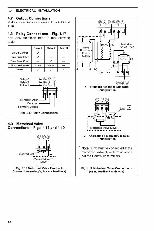
4.7 Output ConnectionsMake connections as shown in Figs 4.15 and4.16.
4.8 Relay Connections – Fig. 4.17For relay functions refer to the followingtable.
A – Standard Feedback SlidewireConfiguration
B – Alternative Feedback SlidewireConfiguration
Note. Link must be connected at themotorized valve drive terminals andnot the Controller terminals.
…4 ELECTRICAL INSTALLATION
7 8
(N)NL(L)
MotorizedValve DriveValve
PositionerPowerSupply
0%100%
5 63 4
100%
Link
0%
2927 28
0% 100%
Motorized Valve Drive
27 2928
Link
Fig. 4.19 Motorized Valve Connections(using feedback slidewire)
4.9 Motorized ValveConnections – Figs. 4.18 and 4.19
437609
58!Relay 3
Relay 2Relay 1
Normally ClosedCommon
Normally Open
Fig. 4.17 Relay Connections
2927 28
Motorized ValveDrive
–Sleeved Link+
Fig. 4.18 Motorized Valve FeedbackConnections (using V, I or mV feedback)
1yaleR 2yaleR 3yaleR
lortnoCffO/nO — —
)taeH(.porPemiT — —
)looC(.porPemiT — —
evlaVdezirotoM nepO esolC —
mralA
15
31
30
32
Logic Input 2
Manual
Automatic Local
Remoteor Dual
Fixed DualSet Point 2
Fixed DualSet Point 1
* AlarmAcknowledge
* Leading 'edge-triggered'(minimum duration 200ms)
5V
0VLogic switching
Auto/Manual
Selection
Local/RemoteSet PointSelection
Dual Set PointSelection
AlarmAcknowledgement
Common
Logic Input 1
Automatic
Manual
Local
Remote (Dual)
Fixed Dual Set Point 2
Alarm Ack.Fixed Dual Set Point 1
323130
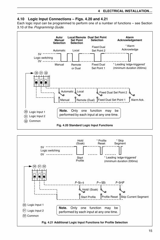
4.10 Logic Input Connections – Figs. 4.20 and 4.21Each logic input can be programmed to perform one of a number of functions – see Section3.10 of the Programming Guide.
Fig. 4.21 Additional Logic Input Functions for Profile Selection
Fig. 4.20 Standard Logic Input Functions
StartProfile
Hold/ (Soak)
Start Profile Profile Reset
Hold(Soak)
* ProfileReset
* SkipSegment
* Leading 'edge-triggered'(minimum duration 200ms)
5V
0VLogic switching
Skip Current Segment
P–SKIPP–Strt P–rSEt
Common
Logic Input 1
Logic Input 2
30
31
32
323130
4 ELECTRICAL INSTALLATION…
Note. Only one function may beperformed by each input at any one time.
Note. Only one function may beperformed by each input at any one time.
16
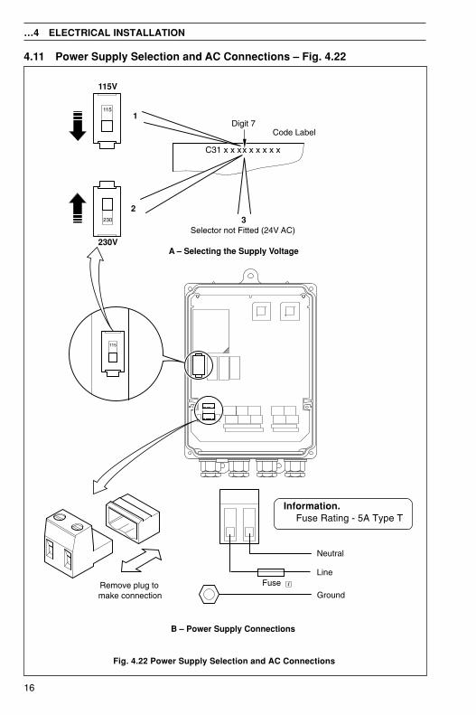
4.11 Power Supply Selection and AC Connections – Fig. 4.22
Fig. 4.22 Power Supply Selection and AC Connections
…4 ELECTRICAL INSTALLATION
Information.Fuse Rating - 5A Type T
115
Selector not Fitted (24V AC)
Code LabelDigit 7
32
1
C31 x x xx x x x x x
115
230
Remove plug tomake connection
A – Selecting the Supply Voltage
B – Power Supply Connections
Line
Neutral
Ground
230V
115V
Fuse
17
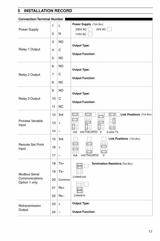
5 INSTALLATION RECORD
Power Supply1
2
3
4
5
6
7
8
9
10
11
12
13
14
15
16
17
18
19
20
21
22
23
24
L
N
NO
C
NC
NO
C
NC
NO
C
NC
3rd
+
–
3rd
+
–
Tx+
Tx–
Common
Rx+
Rx–
+
–
Connection/Terminal Number
RetransmissionOutput
Relay 1 Output
Relay 2 Output
Power Supply
(Tick Box)
230V AC
115V AC
24V AC
Output Type:
Output Function:
Output Type:
Output Function:
Relay 3 Output
Output Type:
Output Function:
(Tick Box)Link Positions
mA VmV/THC/RTD 2-wire Tx
Process VariableInput
VmA mV/THC/RTD
(Tick Box)Link Positions
Remote Set PointInput
Modbus SerialCommunicationsOption 1 only
(Tick Box)Termination Resistors
Linked-out
Linked-in
Output Type:
Output Function:
18
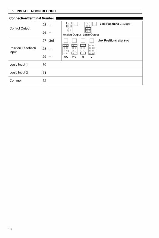
…5 INSTALLATION RECORD
25
26
27
28
29
30
31
32
+
–
3rd
+
–
Connection/Terminal Number
Control Output
Position FeedbackInput
Common
(Tick Box)Link Positions
Analog Output Logic Output
Logic Input 1
Logic Input 2
VmA mV
(Tick Box)Link Positions
R

19
NOTES

20
…NOTES

PRODUCTS & CUSTOMER SUPPORT
ProductsAutomation Systems
• for the following industries:– Chemical & Pharmaceutical– Food & Beverage– Manufacturing– Metals and Minerals– Oil, Gas & Petrochemical– Pulp and Paper
Drives and Motors• AC and DC Drives, AC and DC Machines, AC
motors to 1kV• Drive systems• Force Measurement• Servo Drives
Controllers & Recorders• Single and Multi-loop Controllers• Circular Chart , Strip Chart and Paperless
Recorders• Paperless Recorders• Process Indicators
Flexible Automation• Industrial Robots and Robot Systems
Flow Measurement• Electromagnetic Flowmeters• Mass Flow Meters• Turbine Flowmeters• Flow Elements
Marine Systems & Turbochargers• Electrical Systems• Marine Equipment• Offshore Retrofit and Referbishment
Process Analytics• Process Gas Analysis• Systems Integration
Transmitters• Pressure• Temperature• Level• Interface Modules
Valves, Actuators and Positioners• Control Valves• Actuators• Positioners
Water, Gas & Industrial AnalyticsInstrumentation
• pH, conductivity, and dissolved oxygentransmitters and sensors
• ammonia, nitrate, phosphate, silica, sodium,chloride, fluoride, dissolved oxygen andhydrazine analyzers.
• Zirconia oxygen analyzers, katharometers,hydrogen purity and purge-gas monitors,thermal conductivity.
Customer SupportWe provide a comprehensive after sales service via aWorldwide Service Organization. Contact one of thefollowing offices for details on your nearest Service andRepair Centre.
United KingdomABB LimitedTel: +44 (0)1480 475321Fax: +44 (0)1480 217948
United States of AmericaABB IncTel: +1 215 674 6000Fax: +1 215 674 7183
Client Warranty
Prior to installation, the equipment referred to inthis manual must be stored in a clean, dryenvironment, in accordance with the Company'spublished specification.Periodic checks must be made on theequipment's condition. In the event of a failureunder warranty, the following documentation mustbe provided as substantiation:
1. A listing evidencing process operation and alarmlogs at time of failure.
2. Copies of all storage, installation, operating andmaintenance records relating to the allegedfaulty unit.

IM/C
310–
INS
Issu
e 8
The Company’s policy is one of continuous productimprovement and the right is reserved to modify the
information contained herein without notice.
Printed in UK (10.10)
© ABB 2010
ABB Inc.125 E. County Line RoadWarminsterPA 18974USATel: +1 215 674 6000Fax: +1 215 674 7183
ABB LimitedHoward Road, St. NeotsCambridgeshirePE19 8EUUKTel: +44 (0)1480 475321Fax: +44 (0)1480 217948
ABB has Sales & Customer Support expertisein over 100 countries worldwide
www.abb.com