Embed Size (px)
Citation preview
Business Networking Solution
Installation GuideAuranet Wireless Controller
AC500/AC50


IAbout this Installation Guide
About this Installation GuideThis Installation Guide describes the hardware characteristics, installation methods and the points that should be attended to during the installation. This Installation Guide is structured as follows:
Chapter 1 Introduction.
This chapter describes the external components of the device.
Chapter 2 Installation.
This chapter illustrates how to install the device.
Chapter 3 Lightning Protection.
This chapter illustrates how to prevent lightning damage.
Chapter 4 Connection.
This chapter illustrates how to do the physical connection of the device.
Chapter 5 Configuration.
This chapter illustrates you to configure the device via Web Interface.
Appendix A Troubleshooting.
Appendix B Hardware Specifications.
AudienceThis Installation Guide is for:
Network Engineer Network Administrator
Conventions The figures in Chapter 2 to Chapter 5 are for demonstration purposes only. Your device may differ in appearance from that depicted.
This Guide uses the specific formats to highlight special messages. The following table lists the notice icons that are used throughout this guide.
Remind to be careful. A caution indicates a potential which may result in device damage.
Remind to take notice. The note contains the helpful information for a better use of the product.
Related DocumentThis Installation Guide is also available in PDF on our website. To obtain the latest documentation and product information, please visit the official website:
http://www.tp-link.com
Wireless Controller
II Contents
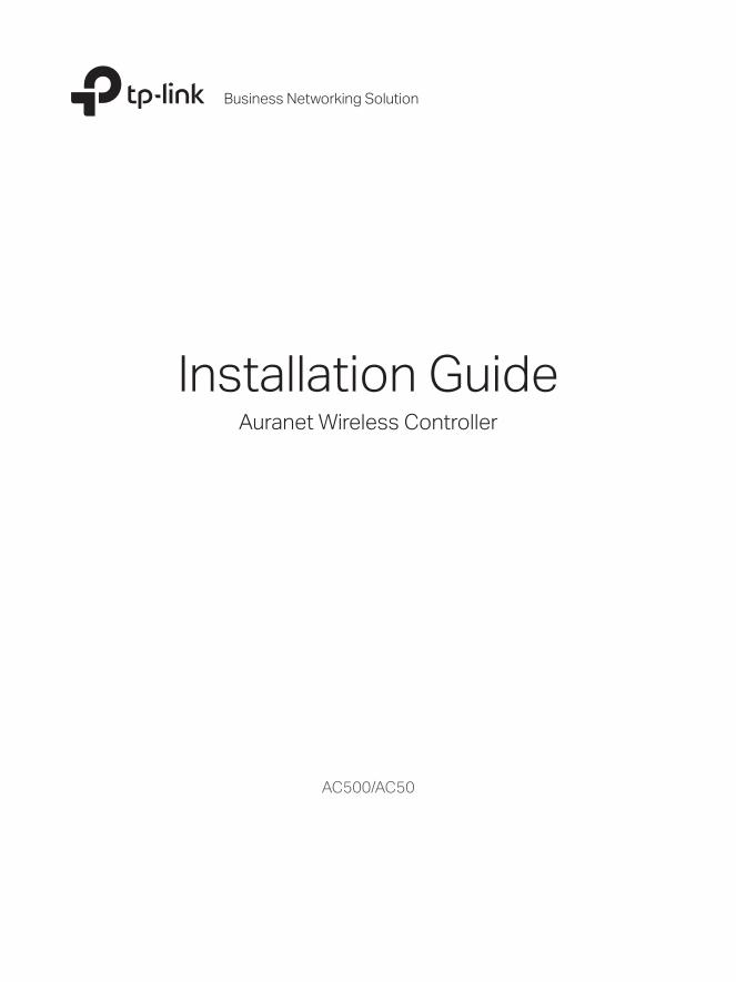
Contents
Chapter 1 Introduction —————————————— 011.1 Product Overview ............................................................................011.2 Appearance ........................................................................................01
Chapter 2 Installation —————————————— 052.1 Package Contents ...........................................................................052.2 Safety Precautions ..........................................................................052.3 Installation Tools ...............................................................................072.4 Product Installation .........................................................................08
Chapter 3 Lightning Protection —————————— 103.1 Cabling Reasonably.........................................................................103.2 Connect to Ground .........................................................................12
Chapter 4 Connection —————————————— 164.1 Ethernet Port .....................................................................................164.2 Verify Installation ..............................................................................164.3 Power On .............................................................................................164.4 Initialization .........................................................................................17
Chapter 5 Configuration ————————————— 185.1 Preparations .......................................................................................185.2 Login .....................................................................................................18
Appendix A Troubleshooting ——————————— 20
Appendix B Hardware Specifications ———————— 22
Wireless Controller
01Introduction
Chapter 1 Introduction
1.1 Product Overview
The Wireless Controller is a device used for centralized management of Access Points (APs). It allows users to configure APs in batches using a web browser and conduct real-time monitoring of each AP in the network. This device supports AP automatic discovery, AP status monitoring, AP centralized control, MAC filtering, radio management, load balance, dual-link backup and various authentication types.
This wireless controller makes it easier to configure and manage dozens or hundreds of APs in a large public environment, such as markets, hotels, companies and campuses, etc. AC500 wireless controller supports to manage 500 APs at the same time and AC50 wireless controller supports 50 APs.
1.2 Appearance
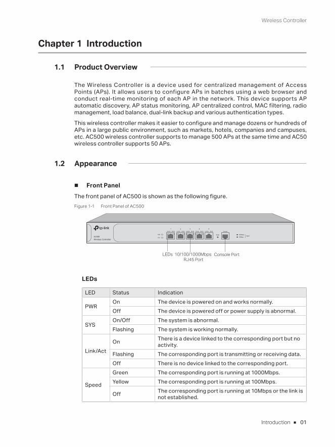
■ Front PanelThe front panel of AC500 is shown as the following figure.Figure 1-1 Front Panel of AC500
10/100/1000Mbps RJ45 Port
LEDs Console Port
LEDs
LED Status Indication
PWROn The device is powered on and works normally. Off The device is powered off or power supply is abnormal.
SYSOn/Off The system is abnormal.Flashing The system is working normally.
Link/ActOn There is a device linked to the corresponding port but no
activity.Flashing The corresponding port is transmitting or receiving data.Off There is no device linked to the corresponding port.
Speed
Green The corresponding port is running at 1000Mbps.Yellow The corresponding port is running at 100Mbps.
Off The corresponding port is running at 10Mbps or the link is not established.
Wireless Controller
02 Introduction
10/100/1000Mbps RJ45 PortDesigned to connect to the device with a bandwidth of 10Mbps, 100Mbps or 1000Mbps. Each has a corresponding Link/Act LED.
Console PortDesigned to connect with the serial port of a computer or terminal for monitoring
and configuring the device.
Note: The console port is only used for debugging by the engineers. Users cannot use the console port to congifure the device at present.
ResetUse the button to restore the wireless controller to the factory defaults. With the device powered on, use a pin to press and hold the Reset button (more than 5 seconds), then release the button. If the SYS LED is flashing quickly about 1 or 2 seconds, it indicates the device is restored successfully.
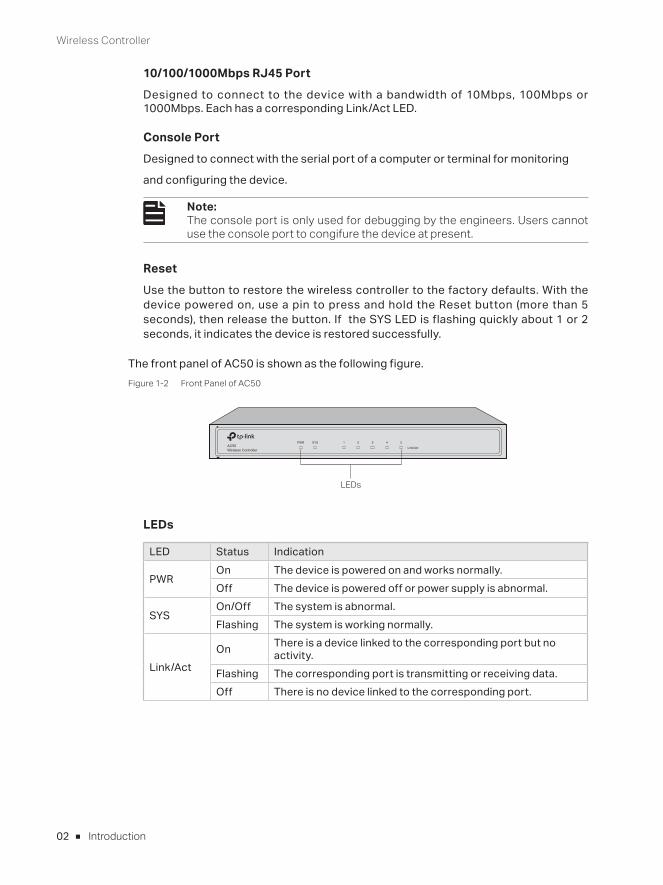
The front panel of AC50 is shown as the following figure.Figure 1-2 Front Panel of AC50
LEDs
LEDs
LED Status Indication
PWROn The device is powered on and works normally.Off The device is powered off or power supply is abnormal.
SYSOn/Off The system is abnormal.Flashing The system is working normally.
Link/ActOn There is a device linked to the corresponding port but no
activity.Flashing The corresponding port is transmitting or receiving data.Off There is no device linked to the corresponding port.
Wireless Controller
03Introduction
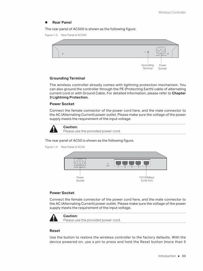
■ Rear PanelThe rear panel of AC500 is shown as the following figure.Figure 1-3 Rear Panel of AC500
100-240V~ 50/60Hz 0.5A
Power Socket
Grounding Terminal
Grounding TerminalThe wireless controller already comes with lightning protection mechanism. You can also ground the controller through the PE (Protecting Earth) cable of alternating current cord or with Ground Cable. For detailed information, please refer to Chapter 3 Lightning Protection.
Power Socket Connect the female connector of the power cord here, and the male connector to the AC (Alternating Current) power outlet. Please make sure the voltage of the power supply meets the requirement of the input voltage.
Caution: Please use the provided power cord.
The rear panel of AC50 is shown as the following figure.Figure 1-4 Rear Panel of AC50
Power Socket
10/100Mbps RJ45 Port
Power Socket Connect the female connector of the power cord here, and the male connector to the AC (Alternating Current) power outlet. Please make sure the voltage of the power supply meets the requirement of the input voltage.
Caution: Please use the provided power cord.
ResetUse the button to restore the wireless controller to the factory defaults. With the device powered on, use a pin to press and hold the Reset button (more than 5
Wireless Controller
04 Introduction
seconds), then release the button. If the SYS LED is flashing quickly about 1 or 2 seconds, it indicates the device is restored successfully.
10/100Mbps RJ45 PortDesigned to connect to the device with a bandwidth of 10Mbps or 100Mbps.
Wireless Controller
05Installation
Chapter 2 Installation
2.1 Package Contents
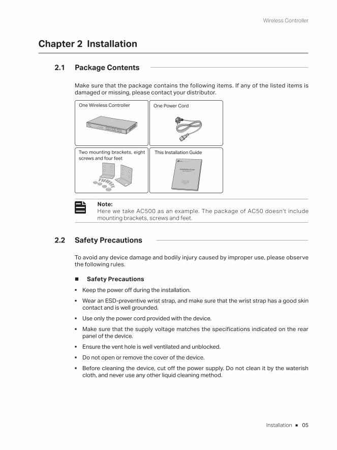
Make sure that the package contains the following items. If any of the listed items is damaged or missing, please contact your distributor.
One Power CordOne Wireless Controller
This Installation Guide
Installation Guide
Business Networking Solution
Two mounting brackets, eight screws and four feet
Note: Here we take AC500 as an example. The package of AC50 doesn't include mounting brackets, screws and feet.
2.2 Safety Precautions
To avoid any device damage and bodily injury caused by improper use, please observe the following rules.
■ Safety Precautions ■ Keep the power off during the installation. ■ Wear an ESD-preventive wrist strap, and make sure that the wrist strap has a good skin
contact and is well grounded. ■ Use only the power cord provided with the device. ■ Make sure that the supply voltage matches the specifications indicated on the rear
panel of the device. ■ Ensure the vent hole is well ventilated and unblocked. ■ Do not open or remove the cover of the device. ■ Before cleaning the device, cut off the power supply. Do not clean it by the waterish
cloth, and never use any other liquid cleaning method.
Wireless Controller
06 Installation
■ Site Requirements
Temperature/Humidity
40℃
0℃
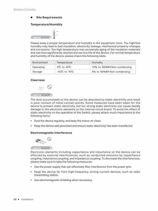
Please keep a proper temperature and humidity in the equipment room. Too high/low humidity may lead to bad insulation, electricity leakage, mechanical property changes and corrosions. Too high temperature may accelerate aging of the insulation materials and can thus significantly shorten the service life of the device. For normal temperature and humidity of the device, please check the following table.
Environment Temperature Humidity
Operating 0℃ to 40℃ 10% to 90%RH Non-condensing
Storage -40℃ to 70℃ 5% to 90%RH Non-condensing
Clearness
The dust accumulated on the device can be absorbed by static electricity and result in poor contact of metal contact points. Some measures have been taken for the device to prevent static electricity, but too strong static electricity can cause deadly damage to the electronic elements on the internal circuit board. To avoid the effect of static electricity on the operation of the Switch, please attach much importance to the following items:
■ Dust the device regularly, and keep the indoor air clean. ■ Keep the device well grounded and ensure static electricity has been transferred.
Electromagnetic Interference
Electronic elements including capacitance and inductance on the device can be affected by external interferences, such as conducted emission by capacitance coupling, inductance coupling, and impedance coupling. To decrease the interferences, please make sure to take the following measures:
■ Use the power supply that can effectively filter interference from the power grid. ■ Keep the device far from high-frequency, strong-current devices, such as radio
transmitting station. ■ Use electromagnetic shielding when necessary.
Wireless Controller
07Installation
Lightening Protection
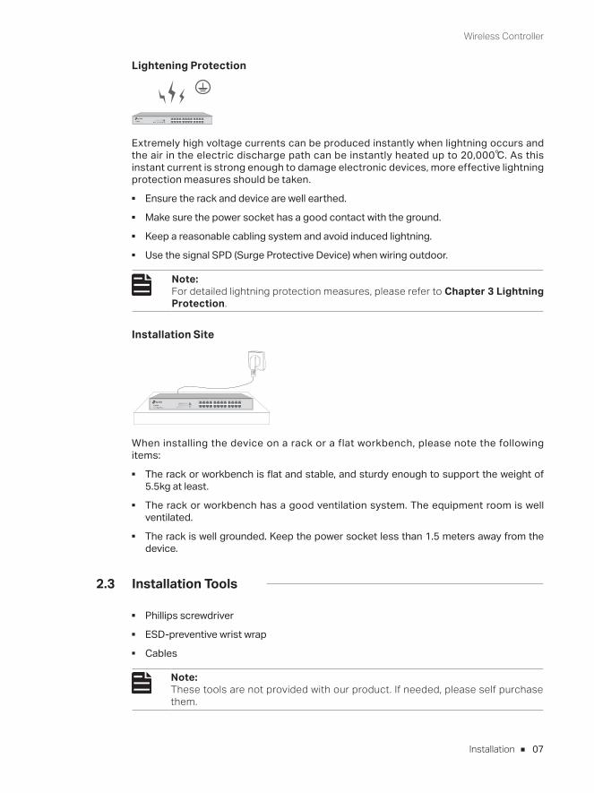
Extremely high voltage currents can be produced instantly when lightning occurs and the air in the electric discharge path can be instantly heated up to 20,000℃. As this instant current is strong enough to damage electronic devices, more effective lightning protection measures should be taken.
■ Ensure the rack and device are well earthed. ■ Make sure the power socket has a good contact with the ground. ■ Keep a reasonable cabling system and avoid induced lightning. ■ Use the signal SPD (Surge Protective Device) when wiring outdoor.
Note: For detailed lightning protection measures, please refer to Chapter 3 Lightning Protection.
Installation Site
When installing the device on a rack or a flat workbench, please note the following items:
■ The rack or workbench is flat and stable, and sturdy enough to support the weight of 5.5kg at least.
■ The rack or workbench has a good ventilation system. The equipment room is well ventilated.
■ The rack is well grounded. Keep the power socket less than 1.5 meters away from the device.
2.3 Installation Tools
■ Phillips screwdriver ■ ESD-preventive wrist wrap ■ Cables
Note: These tools are not provided with our product. If needed, please self purchase them.
Wireless Controller
08 Installation
2.4 Product Installation
■ Desktop InstallationTo install the device on the desktop, please follow the steps:
1. Set the device on a flat surface strong enough to support the entire weight of the device with all fittings.
2. Remove the adhesive backing papers from the rubber feet.
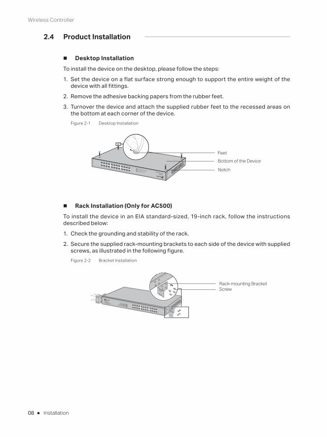
3. Turnover the device and attach the supplied rubber feet to the recessed areas on the bottom at each corner of the device.Figure 2-1 Desktop Installation
FeetBottom of the Device
Notch
■ Rack Installation (Only for AC500)To install the device in an EIA standard-sized, 19-inch rack, follow the instructions described below:
1. Check the grounding and stability of the rack.
2. Secure the supplied rack-mounting brackets to each side of the device with supplied screws, as illustrated in the following figure.Figure 2-2 Bracket Installation
Rack-mounting BracketScrew

Wireless Controller
09Installation
3. After the brackets are attached to the device, use suitable screws (not provided) to secure the brackets to the rack, as illustrated in the following figure.Figure 2-3 Rack Installation
Rack
Caution: ■ Please set 5 to 10cm gaps around the device for air circulation. ■ Please avoid any heavy thing placed on the device. ■ Please mount devices in sequence from the bottom to top of the rack and ensure a certain clearance between devices for the purpose of heat dissipation.
Wireless Controller
10 Lightning Protection
Chapter 3 Lightning Protection
3.1 Cabling Reasonably
In the actual network environment, you may need cable outdoors and indoors, and the requirements for cabling outdoors and indoors are different. A reasonable cabling system can decrease the damage of induced lightning to devices.
Note:It's not recommended using Ethernet cables outdoors. When cabling outdoors, please use a signal lightning arrester.
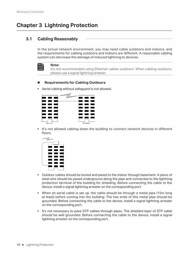
■ Requirements for Cabling Outdoors ■ Aerial cabling without safeguard is not allowed.
■ It’s not allowed cabling down the building to connect network devices in different floors.
■ Outdoor cables should be buried and paved to the indoor through basement. A piece of steel wire should be paved underground along the pipe and connected to the lightning protection terminal of the building for shielding. Before connecting the cable to the device, install a signal lightning arrester on the corresponding port.
■ When an aerial cable is set up, the cable should be through a metal pipe (15m long at least) before coming into the building. The two ends of this metal pipe should be grounded. Before connecting the cable to the device, install a signal lightning arrester on the corresponding port.
■ It’s not necessary to pave STP cables through pipes. The shielded layer of STP cable should be well grounded. Before connecting the cable to the device, install a signal lightning arrester on the corresponding port.
Wireless Controller
11Lightning Protection
■ Requirements for Cabling IndoorsWhen cabling indoors, keep a certain distance away from the devices that may cause high-frequency interferences, such as down-conductor cable, powerline, power transformer and electromotor.
■ The main cable should be paved in the metal raceway of the access shaft. When cabling, keep the loop area formed by the cable itself as small as possible.
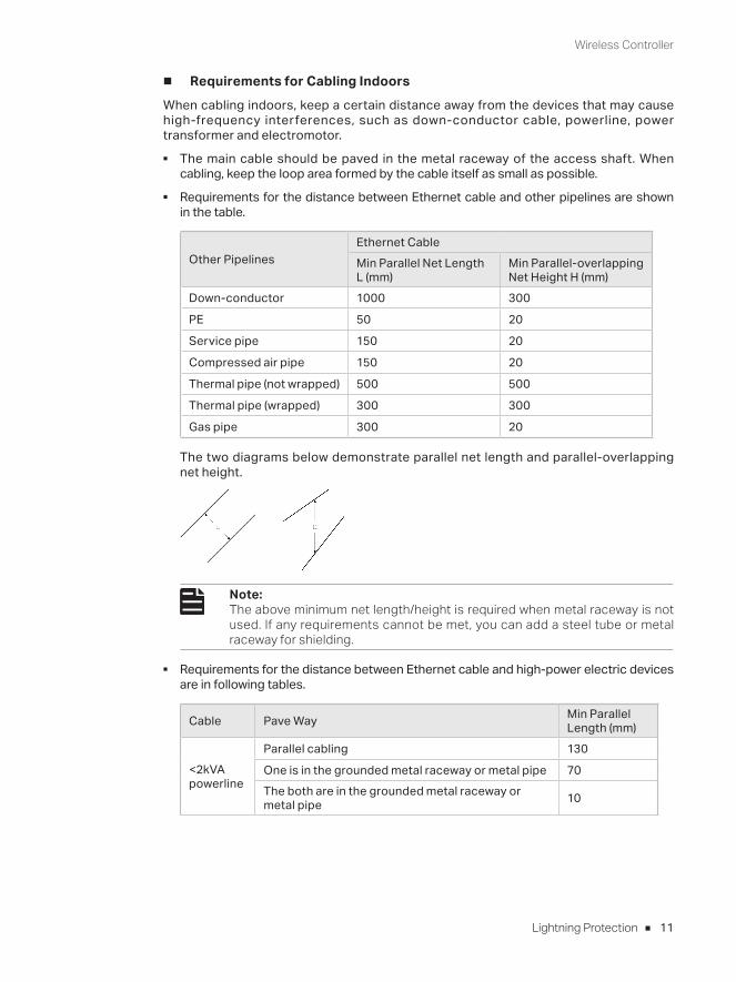
■ Requirements for the distance between Ethernet cable and other pipelines are shown in the table.
Other PipelinesEthernet CableMin Parallel Net Length L (mm)
Min Parallel-overlapping Net Height H (mm)
Down-conductor 1000 300
PE 50 20
Service pipe 150 20
Compressed air pipe 150 20
Thermal pipe (not wrapped) 500 500
Thermal pipe (wrapped) 300 300
Gas pipe 300 20
The two diagrams below demonstrate parallel net length and parallel-overlapping net height.
Note: The above minimum net length/height is required when metal raceway is not used. If any requirements cannot be met, you can add a steel tube or metal raceway for shielding.
■ Requirements for the distance between Ethernet cable and high-power electric devices are in following tables.
Cable Pave Way Min Parallel Length (mm)
<2kVA powerline
Parallel cabling 130
One is in the grounded metal raceway or metal pipe 70The both are in the grounded metal raceway or metal pipe 10
Wireless Controller
12 Lightning Protection
Cable Pave Way Min Parallel Length (mm)
2 to 5kVA powerline
Parallel cabling 300
One is in the grounded metal raceway or metal pipe 150The both are in the grounded metal raceway or metal pipe 80
>5kVA powerline
Parallel cabling 600
One is in the grounded metal raceway or metal pipe 300The both are in the grounded metal raceway or metal pipe 150
Device Min Distance (m)
Switch case 1.00
Transformer room 2.00
Elevator tower 2.00
Air-conditioner room 2.00
3.2 Connect to Ground
Connecting the device to ground is to quickly release the lightning over-voltage and over-current of the device, which is also a necessary measure to protect the body from electric shock.
In different environments, the device may be grounded differently. The following will instruct you to connect the device to the ground in two ways, connecting to the ground via the power supply or connecting to the ground via the grounding terminal. Please connect the device to ground in the optimum way according to your specific operation environment.
Note: For the device without grounding terminal, please refer to the f irst way Connecting to the Ground via the Power Uupply only.
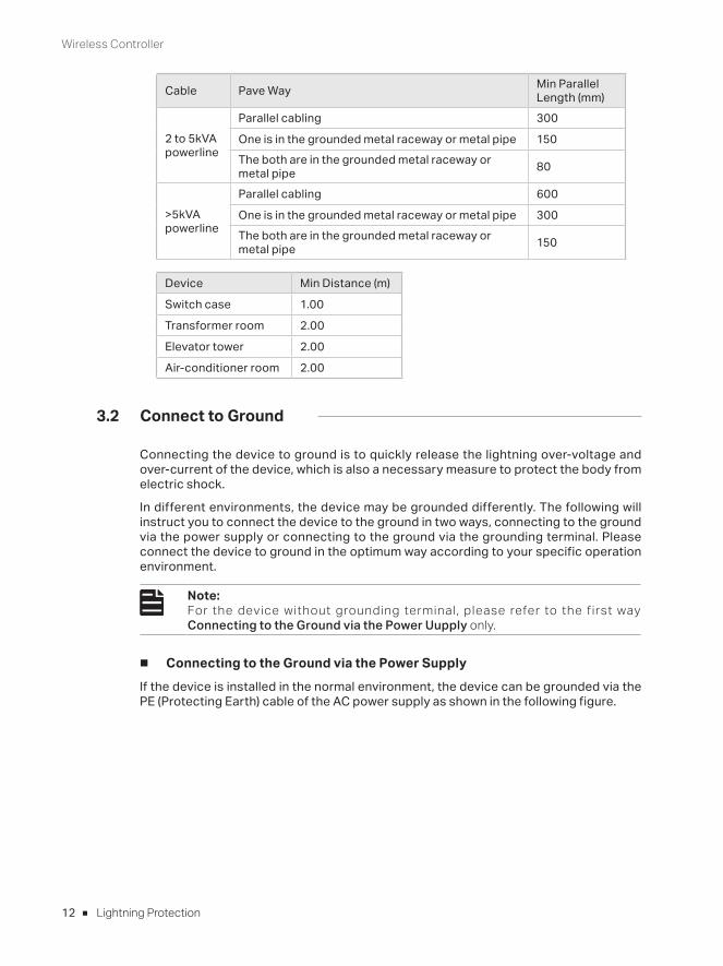
■ Connecting to the Ground via the Power SupplyIf the device is installed in the normal environment, the device can be grounded via the PE (Protecting Earth) cable of the AC power supply as shown in the following figure.
Wireless Controller
13Lightning Protection
Figure 3-1 Connecting to the Ground via Power Supply
Switch (Rear Panel) AC Power Cord (with PE cable)
Note: ■ The figure is to illustrate the application and principle. The power plug you get from the package and the socket in your situation will comply with the regulation in your country, so they may differ from the figure above.
■ If you intend to connect the device to the ground via the PE (Protecting Earth) cable of AC power cord, please make sure the PE (Protecting Earth) cable in the electrical outlet is well grounded in advance.
■ Connecting to the Ground via the Grounding Terminal
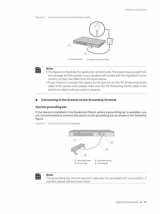
Use the grounding barIf the device is installed in the Equipment Room, where a grounding bar is available, you are recommended to connect the device to the grounding bar as shown in the following figure.Figure 3-2 Connecting to the Grounding Bar
Switch (Rear Panel)Ground Cable
Grounding Terminal
Grounding Bar
Note: The grounding bar and the ground cable are not provided with our product. If needed, please self purchase them.
Wireless Controller
14 Lightning Protection
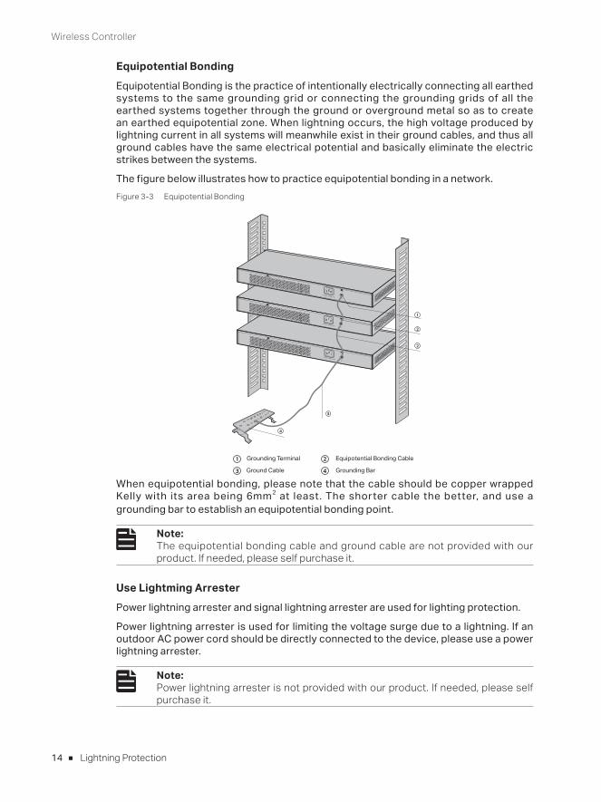
Equipotential BondingEquipotential Bonding is the practice of intentionally electrically connecting all earthed systems to the same grounding grid or connecting the grounding grids of all the earthed systems together through the ground or overground metal so as to create an earthed equipotential zone. When lightning occurs, the high voltage produced by lightning current in all systems will meanwhile exist in their ground cables, and thus all ground cables have the same electrical potential and basically eliminate the electric strikes between the systems.
The figure below illustrates how to practice equipotential bonding in a network.Figure 3-3 Equipotential Bonding
Grounding Terminal Equipotential Bonding Cable
Grounding Bar Ground Cable
When equipotential bonding, please note that the cable should be copper wrapped Kelly with its area being 6mm2 at least. The shorter cable the better, and use a grounding bar to establish an equipotential bonding point.
Note: The equipotential bonding cable and ground cable are not provided with our product. If needed, please self purchase it.
Use Lightming ArresterPower lightning arrester and signal lightning arrester are used for lighting protection.
Power lightning arrester is used for limiting the voltage surge due to a lightning. If an outdoor AC power cord should be directly connected to the device, please use a power lightning arrester.
Note: Power lightning arrester is not provided with our product. If needed, please self purchase it.
Wireless Controller
15Lightning Protection
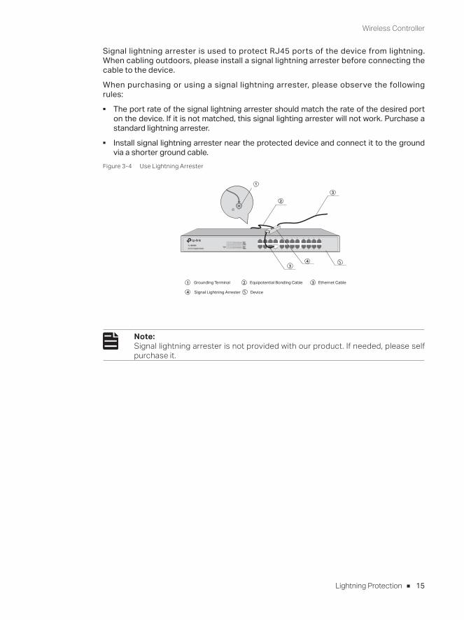
Signal lightning arrester is used to protect RJ45 ports of the device from lightning. When cabling outdoors, please install a signal lightning arrester before connecting the cable to the device.
When purchasing or using a signal lightning arrester, please observe the following rules:
■ The port rate of the signal lightning arrester should match the rate of the desired port on the device. If it is not matched, this signal lighting arrester will not work. Purchase a standard lightning arrester.
■ Install signal lightning arrester near the protected device and connect it to the ground via a shorter ground cable.
Figure 3-4 Use Lightning Arrester
Ethernet CableEquipotential Bonding CableGrounding Terminal
Signal Lightning Arrester Device
Note: Signal lightning arrester is not provided with our product. If needed, please self purchase it.
Wireless Controller
16 Connection
Chapter 4 Connection
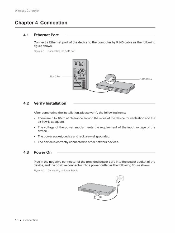
4.1 Ethernet Port
Connect a Ethernet port of the device to the computer by RJ45 cable as the following figure shows.Figure 4-1 Connecting the RJ45 Port
RJ45 PortRJ45 Cable
4.2 Verify Installation
After completing the installation, please verify the following items: ■ There are 5 to 10cm of clearance around the sides of the device for ventilation and the
air flow is adequate. ■ The voltage of the power supply meets the requirement of the input voltage of the
device. ■ The power socket, device and rack are well grounded. ■ The device is correctly connected to other network devices.
4.3 Power On
Plug in the negative connector of the provided power cord into the power socket of the device, and the positive connector into a power outlet as the following figure shows.Figure 4-2 Connecting to Power Supply

Wireless Controller
17Connection
Note: The figure is to illustrate the application and principle. The power plug you get from the package and the socket in your situation will comply with the regulation in your country, so they may differ from the figure above.
4.4 Initialization
After the device is powered on, it begins the Power-On Self-Test. A series of tests run automatically to ensure the device functions properly. During this time, its LED indicators will respond as follows:
For AC500: ■ The PWR LED remains on all the time. ■ The SYS LED keeps flashing quickly. ■ The Link/Act and Speed LEDs flash momentarily and then turn off. ■ The SYS LED flashes quickly for a while. Then it flashes every second continuously,
which represents a successful initialization.
For AC50: ■ The PWR LED remains on all the time. ■ All LEDs except PWR LED flash momentarily, and then turn off. ■ The SYS LED flashes quickly for a while. Then it flashes every second continuously,
which represents a successful initialization.
Wireless Controller
18 Configuration
Chapter 5 Configuration
5.1 Preparations
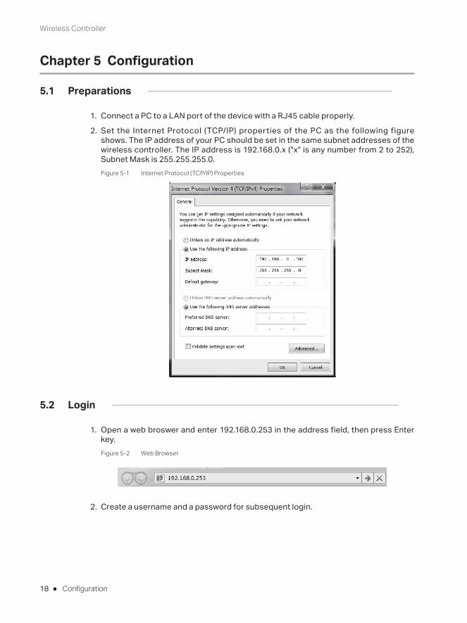
1. Connect a PC to a LAN port of the device with a RJ45 cable properly.
2. Set the Internet Protocol (TCP/IP) properties of the PC as the following figure shows. The IP address of your PC should be set in the same subnet addresses of the wireless controller. The IP address is 192.168.0.x ("x" is any number from 2 to 252), Subnet Mask is 255.255.255.0.Figure 5-1 Internet Protocol (TCP/IP) Properties
5.2 Login
1. Open a web broswer and enter 192.168.0.253 in the address field, then press Enter key.Figure 5-2 Web Browser
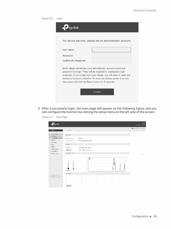
2. Create a username and a password for subsequent login.
Wireless Controller
19Configuration
Figure 5-3 Login
3. After a successful login, the main page will appear as the following figure, and you can configure the function by clicking the setup menu on the left side of the screen.Figure 5-4 Main Page
Wireless Controller
20 Appendix A Troubleshooting
Appendix A Troubleshooting
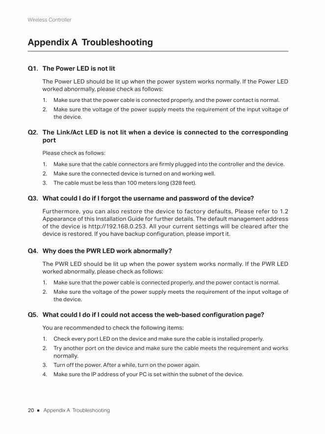
Q1. The Power LED is not lit
The Power LED should be lit up when the power system works normally. If the Power LED worked abnormally, please check as follows:
1. Make sure that the power cable is connected properly, and the power contact is normal.2. Make sure the voltage of the power supply meets the requirement of the input voltage of
the device.
Q2. The Link/Act LED is not lit when a device is connected to the corresponding port
Please check as follows:
1. Make sure that the cable connectors are firmly plugged into the controller and the device.2. Make sure the connected device is turned on and working well.3. The cable must be less than 100 meters long (328 feet).
Q3. What could I do if I forgot the username and password of the device?
Furthermore, you can also restore the device to factory defaults, Please refer to 1.2 Appearance of this Installation Guide for further details. The default management address of the device is http://192.168.0.253. All your current settings will be cleared after the device is restored. If you have backup configuration, please import it.
Q4. Why does the PWR LED work abnormally?
The PWR LED should be lit up when the power system works normally. If the PWR LED worked abnormally, please check as follows:
1. Make sure that the power cable is connected properly, and the power contact is normal.2. Make sure the voltage of the power supply meets the requirement of the input voltage of
the device.
Q5. What could I do if I could not access the web-based configuration page?
You are recommended to check the following items:
1. Check every port LED on the device and make sure the cable is installed properly.2. Try another port on the device and make sure the cable meets the requirement and works
normally.3. Turn off the power. After a while, turn on the power again.4. Make sure the IP address of your PC is set within the subnet of the device.
Wireless Controller
21Appendix A Troubleshooting
5. If you still cannot access the configuration page, please restore the device to its factory defaults. Then the IP address should be set as 192.168.0.x ("x" is any number from 2 to 252) and Subnet Mask as 255.255.255.0.
Q6. Q4. Why does the page display abnormally?
Please check as follows:
1. Update your browser or replace it with another browser, and try again.2. If the pop-up is blocked, please lower the security level of the browser.
■ For more troubleshooting help, go to: http://www.tp-link.com/en/support/faq ■ To download the latest Firmware, Driver, Utility and User Guide, go to:
http://www.tp-link.com/en/support/download
Wireless Controller
22 Appendix B Hardware Specifications
Appendix B Hardware Specifications
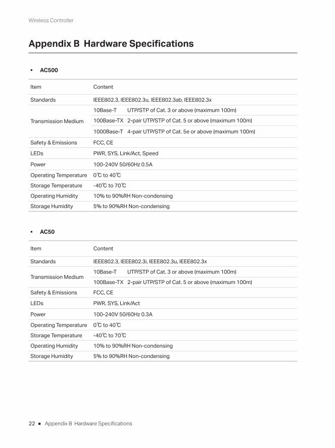
■ AC500
Item Content
Standards IEEE802.3, IEEE802.3u, IEEE802.3ab, IEEE802.3x
Transmission Medium
10Base-T UTP/STP of Cat. 3 or above (maximum 100m)
100Base-TX 2-pair UTP/STP of Cat. 5 or above (maximum 100m)
1000Base-T 4-pair UTP/STP of Cat. 5e or above (maximum 100m)
Safety & Emissions FCC, CE
LEDs PWR, SYS, Link/Act, Speed
Power 100-240V 50/60Hz 0.5A
Operating Temperature 0℃ to 40℃
Storage Temperature -40℃ to 70℃
Operating Humidity 10% to 90%RH Non-condensing
Storage Humidity 5% to 90%RH Non-condensing
■ AC50
Item Content
Standards IEEE802.3, IEEE802.3i, IEEE802.3u, IEEE802.3x
Transmission Medium10Base-T UTP/STP of Cat. 3 or above (maximum 100m)
100Base-TX 2-pair UTP/STP of Cat. 5 or above (maximum 100m)
Safety & Emissions FCC, CE
LEDs PWR, SYS, Link/Act
Power 100-240V 50/60Hz 0.3A
Operating Temperature 0℃ to 40℃
Storage Temperature -40℃ to 70℃
Operating Humidity 10% to 90%RH Non-condensing
Storage Humidity 5% to 90%RH Non-condensing

FCC STATEMENT (AC500)
This equipment has been tested and found to comply with the limits for a Class A digital device, pursuant to part 15 of the FCC Rules. These limits are designed to provide reasonable protection against harmful interference when the equipment is operated in a commercial environment. This equipment generates, uses, and can radiate radio frequency energy and, if not installed and used in accordance with the instruction manual, may cause harmful interference to radio communications. Operation of this equipment in a residential area is likely to cause harmful interference in which case the user will be required to correct the interference at his own expense.
This device complies with part 15 of the FCC Rules. Operation is subject to the following two conditions:
1) This device may not cause harmful interference.
2) This device must accept any interference received, including interference that may cause undesired operation.
Any changes or modifications not expressly approved by the party responsible for compliance could void the user’s authority to operate the equipment.
FCC STATEMENT (AC50)
This equipment has been tested and found to comply with the limits for a Class B digital device, pursuant to part 15 of the FCC Rules. These limits are designed to provide reasonable protection against harmful interference in a residential installation. This equipment generates, uses and can radiate radio frequency energy and, if not installed and used in accordance with the instructions, may cause harmful interference to radio communications. However, there is no guarantee that interference will not occur in a particular installation. If this equipment does cause harmful interference to radio or television reception, which can be determined by turning the equipment off and on, the user is encouraged to try to correct the interference by one or more of the following measures:
• Reorient or relocate the receiving antenna.
• Increase the separation between the equipment and receiver.
• Connect the equipment into an outlet on a circuit different from that to which the receiver is connected.
• Consult the dealer or an experienced radio/ TV technician for help.
This device complies with part 15 of the FCC Rules. Operation is subject to the following two conditions:
1) This device may not cause harmful interference.
2) This device must accept any interference received, including interference that may cause undesired operation.
Any changes or modifications not expressly approved by the party responsible for compliance could void the user’s authority to operate the equipment.
BSMI Notice (AC500)
安全諮詢及注意事項
1) 請使用原裝電源供應器或只能按照本產品注明的電源類型使用本產品。
2) 清潔本產品之前請先拔掉電源線。請勿使用液體、噴霧清潔劑或濕布進行清潔。
3) 注意防潮,請勿將水或其他液體潑灑到本產品上。
4) 插槽與開口供通風使用,以確保本產品的操作可靠並防止過熱,請勿堵塞或覆蓋開口。
5) 請勿將本產品置放於靠近熱源的地方。除非有正常的通風,否則不可放在密閉位置中。
6) 請不要私自打開機殼,不要嘗試自行維修本產品,請由授權的專業人士進行此項工作。
7) 此為甲類資訊技術設備,于居住環境中使用時,可能會造成射頻擾動,在此種情況下,使用者會被要求採取某
些適當的對策。
限用物質含有情況標示聲明書
產品元件名稱
限用物質及其化學符號
鉛
Pb鎘
Cd汞 Hg
六價鉻 CrVI
多溴聯苯
PBB多溴二苯醚
PBDEPCB ○ ○ ○ ○ ○ ○
外殼 ○ ○ ○ ○ ○ ○
備考1. "超出0.1 wt %" 及 "超出0.01 wt %" 系指限用物質之百分比含量超出百分比含量基準值。
備考2. "○"系指該項限用物質之百分比含量未超出百分比含量基準值。
備考3. " - " 系指該項限用物質為排除項目。
BSMI Notice (AC50)
安全諮詢及注意事項
1) 請使用原裝電源供應器或只能按照本產品注明的電源類型使用本產品。
2) 清潔本產品之前請先拔掉電源線。請勿使用液體、噴霧清潔劑或濕布進行清潔。
3) 注意防潮,請勿將水或其他液體潑灑到本產品上。
4) 插槽與開口供通風使用,以確保本產品的操作可靠並防止過熱,請勿堵塞或覆蓋開口。
5) 請勿將本產品置放於靠近熱源的地方。除非有正常的通風,否則不可放在密閉位置中。
6) 請不要私自打開機殼,不要嘗試自行維修本產品,請由授權的專業人士進行此項工作。
限用物質含有情況標示聲明書
產品元件名稱
限用物質及其化學符號
鉛
Pb鎘
Cd汞 Hg
六價鉻 CrVI
多溴聯苯
PBB多溴二苯醚
PBDEPCB ○ ○ ○ ○ ○ ○
外殼 ○ ○ ○ ○ ○ ○
備考1. "超出0.1 wt %" 及 "超出0.01 wt %" 系指限用物質之百分比含量超出百分比含量基準值。
備考2. "○"系指該項限用物質之百分比含量未超出百分比含量基準值。
備考3. " - " 系指該項限用物質為排除項目。
Industry Canada Statement (AC500)
CAN ICES-3 (A)/NMB-3(A)
Industry Canada Statement (AC50)
CAN ICES-3 (B)/NMB-3(B)
CE Mark Warning (AC500)
This is a Class A product. In a domestic environment, this product may cause radio interference, in which case the user may be required to take adequate measures.
CE Mark Warning (AC50)
This is a Class B product. In a domestic environment, this product may cause radio interference, in which case the user may be required to take adequate measures.
Продукт сертифіковано згідно с правилами системи УкрСЕПРО на відповідність вимогам нормативних документів та вимогам, що передбачені чинними законодавчими актами України.
Safety Information• When product has power button, the power button is one of the way to shut off the product; when
there is no power button, the only way to completely shut off power is to disconnect the product or the power adapter from the power source.
• Don’t disassemble the product, or make repairs yourself. You run the risk of electric shock and voiding the limited warranty. If you need service, please contact us.
• Avoid water and wet locations.
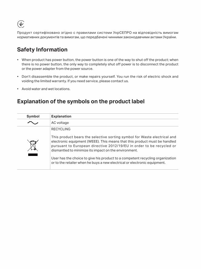
Explanation of the symbols on the product label
Symbol Explanation
AC voltage
RECYCLING
This product bears the selective sorting symbol for Waste electrical and electronic equipment (WEEE). This means that this product must be handled pursuant to European directive 2012/19/EU in order to be recycled or dismantled to minimize its impact on the environment.
User has the choice to give his product to a competent recycling organization or to the retailer when he buys a new electrical or electronic equipment.


© 2017 TP-Link 7106507669 REV1.0.2
The products of TP-Link partly contain software code developed by third parties, including software code subject to the GNU General Public License (“GPL”). As applicable, the terms of the GPL and any information on obtaining access to the respective GPL Code used in TP-Link products are available to you in GPL-Code-Centre under (http://www.tp-link.com/en/support/gpl/). The respective programs are distributed WITHOUT ANY WARRANTY and are subject to the copyrights of one or more authors. For details, see the GPL Code and other terms of the GPL.
For technical support and other information, please visit http://www.tp-link.com/support, or simply scan the QR code.


![Mokushiroku Arisu (Apocalypse Alice)_V1 [Light Novel - Shounen]](https://img.pdfslide.us/doc/110x75/55cf94cf550346f57ba487dd/mokushiroku-arisu-apocalypse-alicev1-light-novel-shounen.jpg)