Embed Size (px)
Citation preview
Installation Guide: Timber stairs A Guide to safe stair installation from the BWF Stair Scheme
Produced for JELD-WEN (UK) Ltd © 2014 British Woodworking Federation
BWF Timber Stair Installation Guide www.higginson.co.uk 2 | P a g e
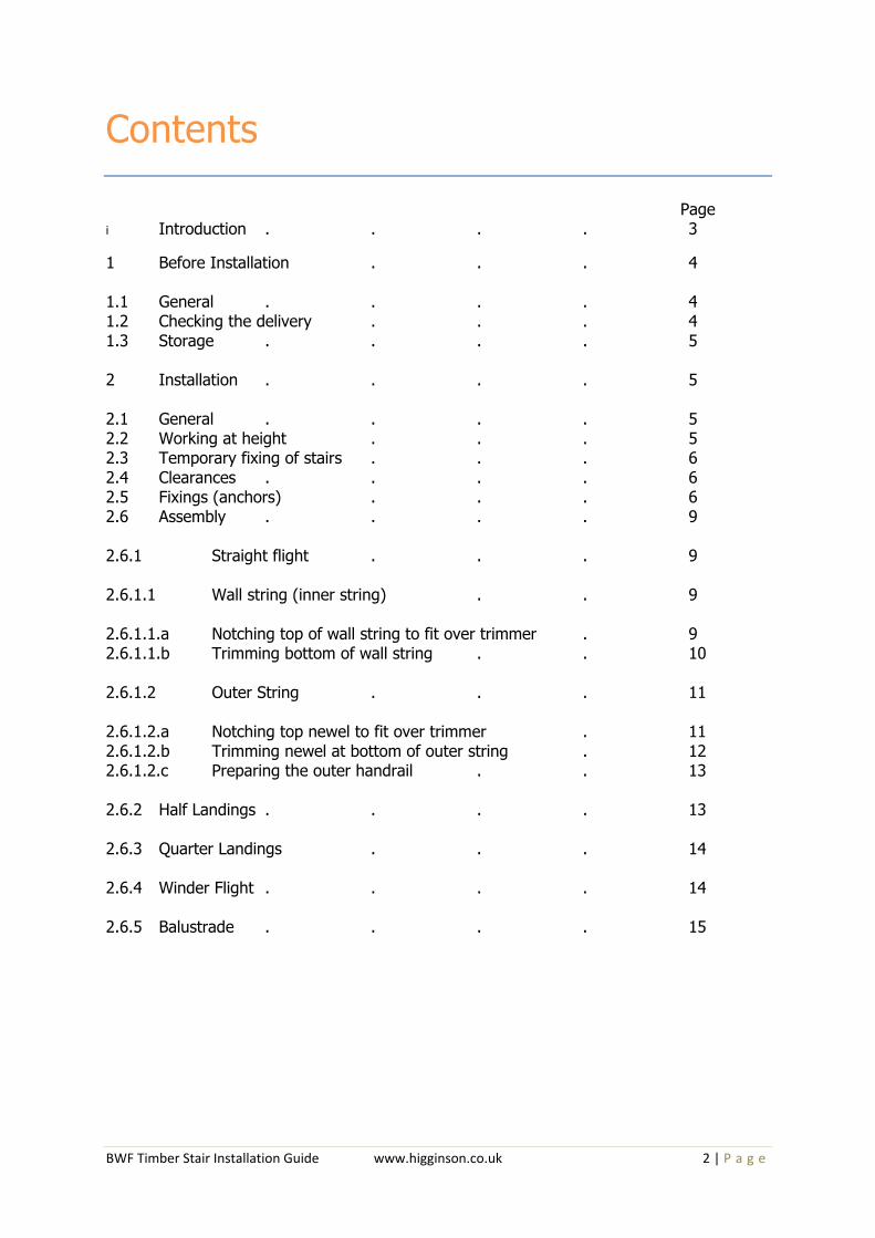
Contents
Page
i Introduction . . . . 3
1 Before Installation . . . 4 1.1 General . . . . 4 1.2 Checking the delivery . . . 4 1.3 Storage . . . . 5 2 Installation . . . . 5 2.1 General . . . . 5 2.2 Working at height . . . 5 2.3 Temporary fixing of stairs . . . 6 2.4 Clearances . . . . 6 2.5 Fixings (anchors) . . . 6 2.6 Assembly . . . . 9 2.6.1 Straight flight . . . 9 2.6.1.1 Wall string (inner string) . . 9 2.6.1.1.a Notching top of wall string to fit over trimmer . 9 2.6.1.1.b Trimming bottom of wall string . . 10 2.6.1.2 Outer String . . . 11 2.6.1.2.a Notching top newel to fit over trimmer . 11 2.6.1.2.b Trimming newel at bottom of outer string . 12 2.6.1.2.c Preparing the outer handrail . . 13 2.6.2 Half Landings . . . . 13 2.6.3 Quarter Landings . . . 14 2.6.4 Winder Flight . . . . 14 2.6.5 Balustrade . . . . 15

BWF Timber Stair Installation Guide www.higginson.co.uk 3 | P a g e
i Introduction The BWF Stair Scheme Installation Guide is intended to provide general information about installing timber staircases, focusing on key areas to ensure that the stairs are safe to use and not compromised by poor practice. The members of the BWF Stair Scheme design and manufacture their stairs so that they will support the necessary loads in both the flights and the balustrades, but poor installation can cause the stability of the stair to be reduced, possibly leading to premature failure of components and ultimately the collapse of the stair.
The installation process itself has inherent risks and care should be taken to adequately support the stair until all the necessary fixings to the surrounding structure are in place. No stair should be used for access until its full load bearing capacity has been achieved and it is securely fixed in place.
If you are looking for simple factsheets and toolbox talks to help project the essence of this guide –“Top Ten Tips to avoid common staircase problems” is available via www.bwfstairscheme.org.uk as a fact sheet and electronic presentation.
It’s All in The Badge
The BWF Stair Scheme is the only accreditation and certification scheme of its kind in the UK. Ranging from domestic, common and fire protected common stairs, the standard expected of the manufacturers for their stairs is high with a drive to improve quality and safety in use, supported by an effective factory production control system and adherence to the core principles and values laid down in the BWF Code of Conduct.
All companies within the scheme are regularly audited to ensure their products and their production meet these high standards, and the new third-party certification for fire protected common stairs, supported by The Loss Prevention Certification Board (LPCB) is opening up new markets for timber stairs. The scheme is managed by the BWF, and includes manufacturers, as well as approved suppliers, who play an important part in maintaining these high standards.
Whilst the BWF Stair Scheme does not accredit installation, guidance is available on the installation of staircases.

BWF Timber Stair Installation Guide www.higginson.co.uk 4 | P a g e
1 Before Installation
1.1 General
To ensure the minimum time required for site storage plan the delivery of the stair to be close to the time when it will be installed.
Take care when handling stair components, particularly long flights, as these can be heavy and may need an assisted lift.
1.2 Checking the delivery When the stair is delivered to site check the delivery against manufacturer’s documentation:
1. quantity of components
o Main stair components, flights,
newels, bullnose treads, curtail
treads, winder treads. Risers for
winders
o Wedges and glue blocks, dowels,
top nosings
o Balustrade and ancillary items o Handrail, string capping, landing
base rail, apron lining, balusters,
infill fillets
2. any damage
3. quality of components and grade
(appearance) of materials
4. Also check the “as-built” dimensions on site to
ensure that no changes have occurred and to
confirm that the supplied stair will fit in the
stair well.
BWF Timber Stair Installation Guide www.higginson.co.uk 5 | P a g e
1.3 Storage
Ideally arrange for the staircase to be delivered when you are ready to install it.
If necessary stair components should be stored in clean, well ventilated conditions, protected from damp and direct sunlight.
Long items should be kept flat on bearers. If components are delivered for more than one stair,
store the parts for each stair separately or mark each item so that they can be easily identified. Do not mix stair parts when installing as stairs will usually be made to suit a particular stairwell arrangement.
If storing stairs in the building take care not to overload any part of the structure by stacking too many parts together. On upper floors store components near to walls on which the floor joists bear, rather than in the centre of rooms.
2 Installation
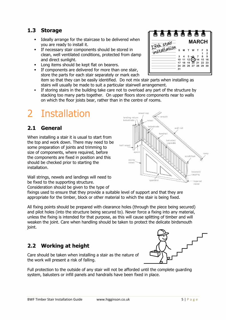
2.1 General
When installing a stair it is usual to start from the top and work down. There may need to be some preparation of joints and trimming to size of components, where required, before the components are fixed in position and this should be checked prior to starting the installation.
Wall strings, newels and landings will need to be fixed to the supporting structure. Consideration should be given to the type of fixings used to ensure that they provide a suitable level of support and that they are appropriate for the timber, block or other material to which the stair is being fixed.
All fixing points should be prepared with clearance holes (through the piece being secured) and pilot holes (into the structure being secured to). Never force a fixing into any material, unless the fixing is intended for that purpose, as this will cause splitting of timber and will weaken the joint. Care when handling should be taken to protect the delicate birdsmouth joint.
2.2 Working at height
Care should be taken when installing a stair as the nature of the work will present a risk of falling.
Full protection to the outside of any stair will not be afforded until the complete guarding system, balusters or infill panels and handrails have been fixed in place.

BWF Timber Stair Installation Guide www.higginson.co.uk 6 | P a g e
As an alternative, a suitably accredited temporary guarding system may be used until the final guarding is in place. (Accredited to EN 13374:2004, Temporary edge protection systems. Product specification. Test Methods.)
The Health and Safety Executive publish advice on working at height on their website at:
http://www.hse.gov.uk/construction/safetytopics/workingatheight.htm
2.3 Temporary fixing of stairs
A staircase will not be able to provide its full support until it is installed completely with all fixings in place. Until this is achieved there is a chance that elements of the stair could become dislodged from their positions, for example, a newel could fall from its location over a trimmer, or a missing fixing or anchor, could cause unexpected loading to a part of the stair leading to failure.
During the installation process it may be necessary for the installer to use the stair, but this should only be undertaken with caution having ensured that temporary supports, such as a block at the base of the stair to prevent slipping, or temporary propping, is in place before the installer applies any load to the stair. At this time, no guarding will have been fitted so the installer should also consider any risks associated with falling from the stair.
Before a staircase is used for access between storeys the trunk should be fully installed and capable of supporting its intended loads with all fixings, packers and supports in place. Any edges where there is a risk of falling should be protected by the supplied guarding or balustrade or by adequate temporary guarding. (Temporary guarding should be accredited to EN 13374:2004, Temporary edge protection systems. Product specification. Test Methods)
2.4 Clearances
The finished size of the stair should not be equal to the sizes measured on site, as this will not afford any flexibility while installing the stair and may not permit parts of the flight to be manoeuvred into position. Consideration should also be given to any finishes that are yet to be applied to the walls of the stair opening, such as, dry lining or plastering. The finished size of a stair can be up to 40 mm less than the “tight” sizes measured on site but any clearances between the stair and any fixing points should be packed out prior to fixing.
2.5 Wall string fixings
Structural screws, which are CE marked to EN 14592, should be used to fix wall strings to timber stud walls or masonry walls. The screws should have a nominal diameter of 5 mm (10 gauge), and should either be of the self-drilling type, or should be installed in predrilled holes. The length of the screw should be chosen to achieve a minimum penetration of 50 mm into the timber stud/nogging or into the masonry wall, and 50 mm long wall plugs should be used in masonry walls (see Figure 1a).

BWF Timber Stair Installation Guide www.higginson.co.uk 7 | P a g e
A continuous timber packer of sufficient width to avoid the possibility of splitting should be fixed directly to the wall to fill the gap between the stair string and the timber/masonry wall.
The centres appropriate for fixing stair wall strings (including winder strings) are given in Table 1, depending on the size of the gap between the stair string and the wall, and whether the stair is for private or general access.
Figure 1a. Section through wall string at stud wall and blockwork
Table 1 – Recommended Stair String Fixing Centres
(Using 5 mm diameter screws penetrating min 50mm into the wall)
Stair usage String-wall gaps up to 40 mm String-wall gaps exceeding 40
mm
Private (domestic)
Max 600 mm centres (see Fig 1b)
Max 300 mm centres (see Fig 1c)
General access (eg flats)
Max 300 mm centres (see Fig 1c)
Seek specialist advice from a structural engineer
Stair string fixing should begin with screws being provided beneath the top and bottom treads.
Working from these top and bottom fixings, additional screws should then be inserted at centres no greater than those noted in Table 1, working toward the centre of the string. Note that this will often result in two fixings being necessary beneath winder treads.

BWF Timber Stair Installation Guide www.higginson.co.uk 8 | P a g e
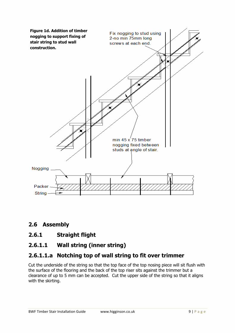
To facilitate fixing into timber stud walls, timber noggings should be provided between the vertical timber studs which follow the intended line of the fixings. These timber noggings should be a minimum of 45 mm wide x 72 mm deep, and be fixed to the timber studs at each end using 2No 75 mm long screws inserted perpendicular to the nogging (see Figure 1d). Alternatively, additional studs may be provided at 300 mm c/c to enable direct fixing into studs and avoid the need to insert noggings.
Figure 1b Fixing Centres for private stairs with gaps between string and wall of less than 40 mm
Figure 1c Fixing centres for Private stairs with gaps between string and wall exceeding 40 mm, or General Access stairs with gaps less than 40 mm.
BWF Timber Stair Installation Guide www.higginson.co.uk 9 | P a g e
2.6 Assembly
2.6.1 Straight flight
2.6.1.1 Wall string (inner string)
2.6.1.1.a Notching top of wall string to fit over trimmer
Cut the underside of the string so that the top face of the top nosing piece will sit flush with the surface of the flooring and the back of the top riser sits against the trimmer but a clearance of up to 5 mm can be accepted. Cut the upper side of the string so that it aligns with the skirting.
Figure 1d. Addition of timber
nogging to support fixing of
stair string to stud wall
construction.
BWF Timber Stair Installation Guide www.higginson.co.uk 10 | P a g e
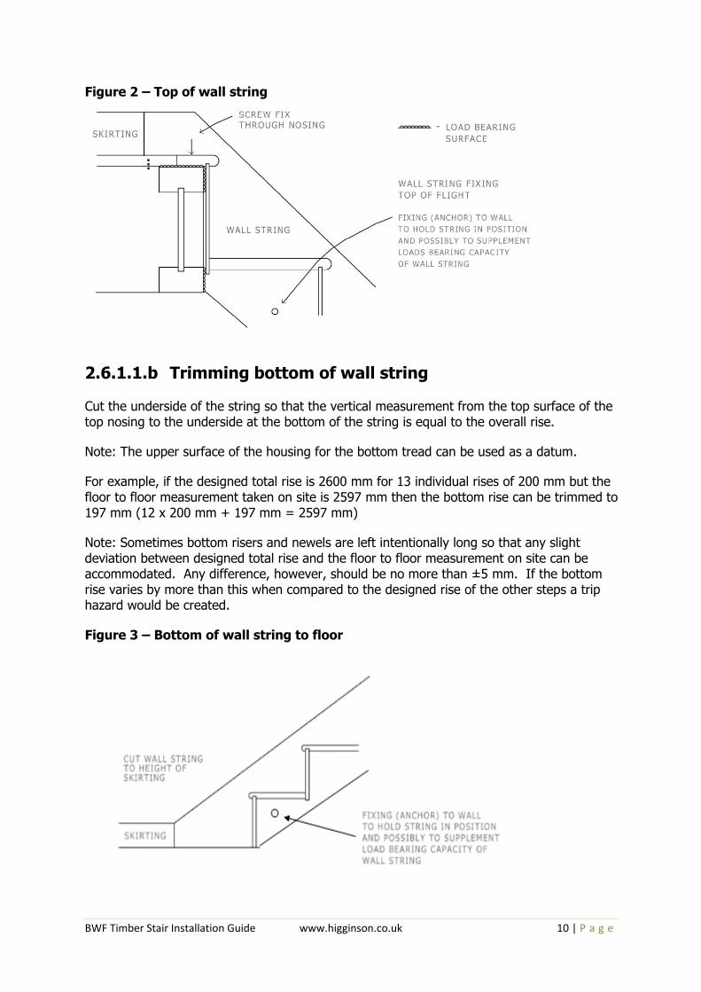
Figure 2 – Top of wall string
2.6.1.1.b Trimming bottom of wall string Cut the underside of the string so that the vertical measurement from the top surface of the top nosing to the underside at the bottom of the string is equal to the overall rise.
Note: The upper surface of the housing for the bottom tread can be used as a datum.
For example, if the designed total rise is 2600 mm for 13 individual rises of 200 mm but the floor to floor measurement taken on site is 2597 mm then the bottom rise can be trimmed to 197 mm (12 x 200 mm + 197 mm = 2597 mm)
Note: Sometimes bottom risers and newels are left intentionally long so that any slight deviation between designed total rise and the floor to floor measurement on site can be accommodated. Any difference, however, should be no more than ±5 mm. If the bottom rise varies by more than this when compared to the designed rise of the other steps a trip hazard would be created.
Figure 3 – Bottom of wall string to floor

BWF Timber Stair Installation Guide www.higginson.co.uk 11 | P a g e
Figure 4 – Bottom of wall string to trimmer
2.6.1.2 Outer String The outer string is usually jointed at the top and bottom ends into newel posts (or newel bases). The most common form of joint is a mortise and tenon joint, although stair manufacturers may provide an alternative method of securing the newels to the outer string.
Follow the instructions from the stair manufacturer to ensure the string-to-newel joints are formed correctly.
Before fixing, the newels to the outer string will need to be prepared as follows;
2.6.1.2.a Notching top newel to fit over trimmer
The back face of the newel will need to be notched to receive the trimmer. The notching should position the top of the top nosing flush with the surface of the floor and the back face of the top riser with the same clearance as created by the cutting of the wall string.
Note: Notch the newel to the depth of the trimmer, but do not fit the newel over the flooring. Remove the flooring (i.e. chipboard) to accommodate the wall string, newel and top nosing.
Figure 5 – Top of outer string
Fixings are to be
structural screws,
which are CE
marked to EN
14592, 6mm x
90mm
Screw fix
Screw fix
Screw fix
Screw fix

BWF Timber Stair Installation Guide www.higginson.co.uk 12 | P a g e
2.6.1.2.b Trimming newel at bottom of outer string Before fixing the bottom newel to the outer string the bottom end of the newel may need to be trimmed to the correct total rise or floor to floor site measurement. (refer back to the section on cutting the wall string).
Note: the bottom newel may not be at the bottom of the flight. There could be up to two additional steps to be fitted, for example, a bullnose step, or a bullnose step together with a curtail step.
Figure 6 – Bottom of wall string on trimmer
Figure 7 – Bottom treads - side view
Noggin pieces are
often required to
support the
bullnose tread
It may be necessary
to remove bottom of
newel to assist with
access for fitting
Fixings are to be
structural screws,
which are CE marked
to EN 14592, 6mm x
90mm

BWF Timber Stair Installation Guide www.higginson.co.uk 13 | P a g e
Figure 8 – Bottom treads - plan view
2.6.1.2.c Preparing the outer handrail
Handrails are used to support a person using the stairs in the event of a trip or a slip and to provide assistance to people with impaired movement. Handrails can also form the top of a balustrade or “safety barrier” protecting users of the stair from falling. It is essential that handrails are fixed securely.
Once the top and bottom newels have been fixed in position it will not be possible to “spring-in” a tenoned handrail. Do not remove the tenons as this will weaken the joint between the handrail and the newel.
If the handrail is provided with a mechanical fixing system please refer to the manufacturer’s instructions.
Note: A handrail on its own cannot act as a safety barrier. Full protection from falling will only be afforded by the completed guarding system or a suitably accredited temporary guarding system.
2.6.2 Half Landings
Half landings will need to support the same loads as the floors of the property into which the stair is being installed.
The trimmer onto which the top of one flight and the bottom of the second flight will bear will need to support the loads imposed when the flights are being used.
Unless specified otherwise half landings should use the following minimum joist sizes up to a maximum landing size 1.2 m x 2.6 m.
BWF Timber Stair Installation Guide www.higginson.co.uk 14 | P a g e
Table 2 - Joist and trimmer sizes for half landings
Type of stair Joists at walls and at 600 mm centres max (mm)
Trimmer between walls (mm)
Domestic 47 x 147 2 x 47 x 195
Common 47 x 195 2 x 47 x 225
Trimmers should be let into the walls, but not into cavities, for support or supported by joist hangers. Joists can be screwed or bolted to walls. Where trimmers are doubled, the two sections should be screwed or bolted together to avoid slippage and to share the imposed loads from the flights.
The top of the lower flight should be prepared as if the landing was an upper floor (see Figure 4). The bottom of the upper flight should be prepared as if the landing was the lower floor with the newel finishing in-line with the bottom riser (see Figure 5).
The flights should bear on the trimmer and not on the boarding used to form the surface of the landing. This will allow the boarding to be replaced if it becomes damaged. To maintain the rise of the bottom step is consistent with the rest of the flight, an allowance equal to the thickness of the boarding of the landing will need to be made when cutting the string or newel and bottom riser for height.
2.6.3 Quarter landing
Quarter landings will need to be able to support the same loads as the floors of the property into which the stair is being installed.
The newel forming the corner of the stair where the outer string turns through 90 degrees will need to be notched to receive and support the outer corner of the landing, unless the newel is designed to be face fixed.
If the newel is to be notched, it will need to act as both a “top” and “bottom” newel for the outer strings and be prepared in two directions accordingly.
The joist sizes should be as given above for half landings in Table 2. (Trimmers are not required for quarter landings.)
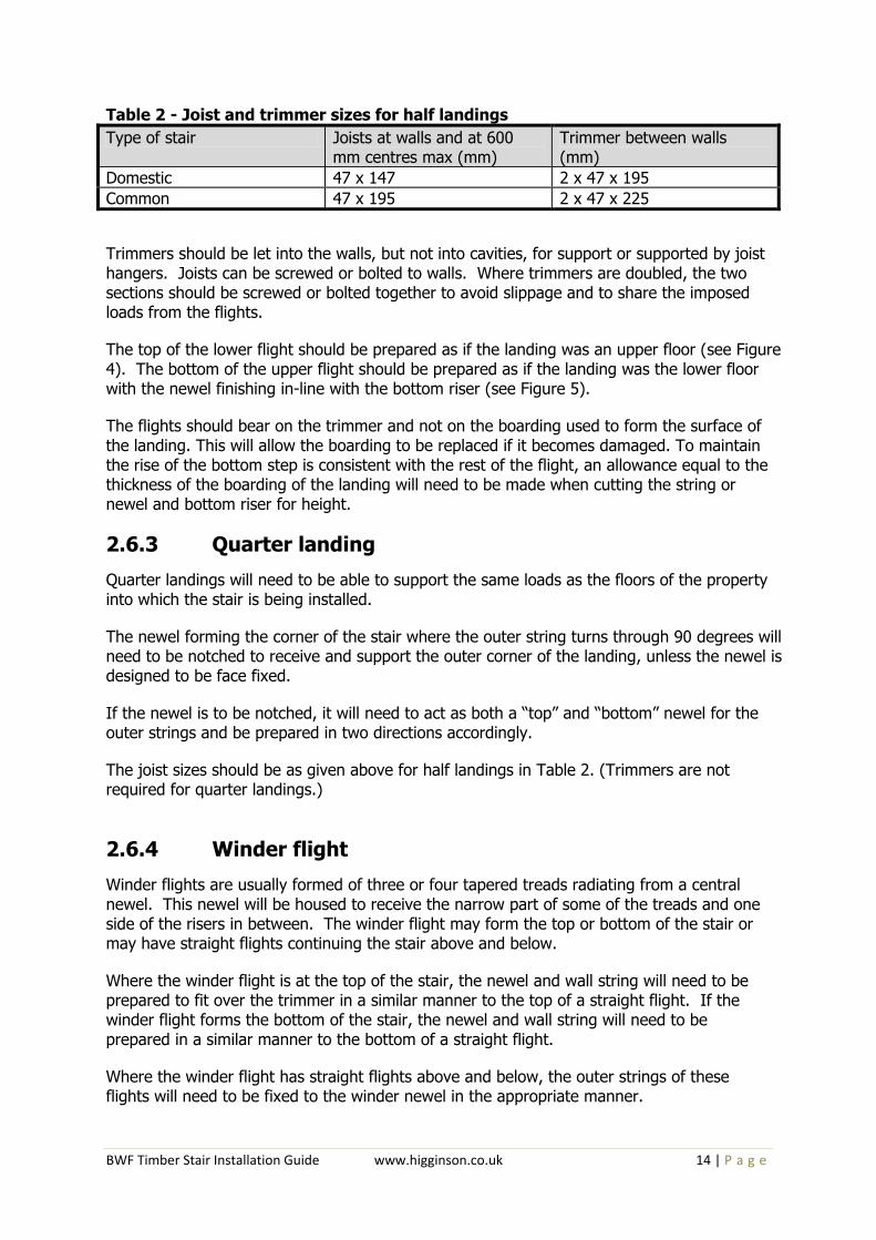
2.6.4 Winder flight
Winder flights are usually formed of three or four tapered treads radiating from a central newel. This newel will be housed to receive the narrow part of some of the treads and one side of the risers in between. The winder flight may form the top or bottom of the stair or may have straight flights continuing the stair above and below.
Where the winder flight is at the top of the stair, the newel and wall string will need to be prepared to fit over the trimmer in a similar manner to the top of a straight flight. If the winder flight forms the bottom of the stair, the newel and wall string will need to be prepared in a similar manner to the bottom of a straight flight.
Where the winder flight has straight flights above and below, the outer strings of these flights will need to be fixed to the winder newel in the appropriate manner.
BWF Timber Stair Installation Guide www.higginson.co.uk 15 | P a g e
In all cases the two sections of the wall string will need to be joined together. If the stair is being installed from the top down then the upper wall string will be extended to the full width of the stair and the end of the wall string of the lower flight will be fixed to it.
Due to site limitations, it is not always possible to assemble a winder flight as described above. In this instance the flight should be fully assembled and either lowered or raised into position.
2.6.5 Balustrade Other than at the two bottom steps, a barrier is required to protect users of the stair from falling. This is often provided by a balustrade formed by individual balusters or spindles. So as to provide the necessary protection it is important that the balustrade is fixed securely.
Once the stair has been fully assembled and secured in place the balustrade can be fitted. If the balustrade has been delivered as an assembled unit then fit in accordance with the manufacturer’s instructions.
If the balustrade has been delivered as components, start to form the balustrade by cutting to length and angling the ends of the string capping, balusters or spindles and infill piece.
The string capping should be cut to fit tightly between the newels with its ends angled to suit the pitch of the flight. Once cut the string capping should be screw fixed to the string starting 50 mm from each end and then at no more than 450 mm centres.
The balusters or spindles should be cut to length so that they fully engage into the groove in the underside of the handrail and the upper face of the string capping. Again, the ends of the balusters should be angled to the pitch of the stair. It is important that balusters are fully housed by the handrail and string capping or they may not provide the necessary protection to users of the stair.
BWF Timber Stair Installation Guide www.higginson.co.uk 16 | P a g e
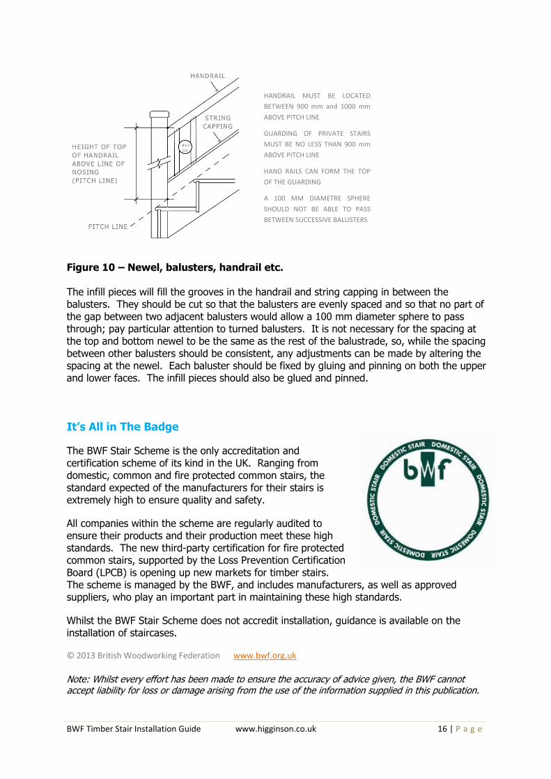
Figure 10 – Newel, balusters, handrail etc. The infill pieces will fill the grooves in the handrail and string capping in between the balusters. They should be cut so that the balusters are evenly spaced and so that no part of the gap between two adjacent balusters would allow a 100 mm diameter sphere to pass through; pay particular attention to turned balusters. It is not necessary for the spacing at the top and bottom newel to be the same as the rest of the balustrade, so, while the spacing between other balusters should be consistent, any adjustments can be made by altering the spacing at the newel. Each baluster should be fixed by gluing and pinning on both the upper and lower faces. The infill pieces should also be glued and pinned.
It’s All in The Badge
The BWF Stair Scheme is the only accreditation and certification scheme of its kind in the UK. Ranging from domestic, common and fire protected common stairs, the standard expected of the manufacturers for their stairs is extremely high to ensure quality and safety.
All companies within the scheme are regularly audited to ensure their products and their production meet these high standards. The new third-party certification for fire protected common stairs, supported by the Loss Prevention Certification Board (LPCB) is opening up new markets for timber stairs. The scheme is managed by the BWF, and includes manufacturers, as well as approved suppliers, who play an important part in maintaining these high standards.
Whilst the BWF Stair Scheme does not accredit installation, guidance is available on the installation of staircases.
© 2013 British Woodworking Federation www.bwf.org.uk Note: Whilst every effort has been made to ensure the accuracy of advice given, the BWF cannot accept liability for loss or damage arising from the use of the information supplied in this publication.
HANDRAIL MUST BE LOCATED
BETWEEN 900 mm and 1000 mm
ABOVE PITCH LINE
GUARDING OF PRIVATE STAIRS
MUST BE NO LESS THAN 900 mm
ABOVE PITCH LINE
HAND RAILS CAN FORM THE TOP
OF THE GUARDING
A 100 MM DIAMETRE SPHERE
SHOULD NOT BE ABLE TO PASS
BETWEEN SUCCESSIVE BALUSTERS

BWF Timber Stair Installation Guide www.higginson.co.uk 17 | P a g e

BWF Timber Stair Installation Guide www.higginson.co.uk 18 | P a g e
Website www.bwfstairscheme.org.uk
Address Stair Scheme, The Building Centre26 Store Street, London WC1E 7BT
Twitter @BWFstairs
Pinterest BWFStairScheme
Telephone 0844 209 2610
“It’s all in the Badge”
Website www.jeld-wen.co.uk
Address Snow Hill, Melton Mowbray, Leicestershire LE13 1PD
Telephone 0845 122 2894
© 2014 British Woodworking Federation