Embed Size (px)
Citation preview
Installation guide Roof reflector Page 1
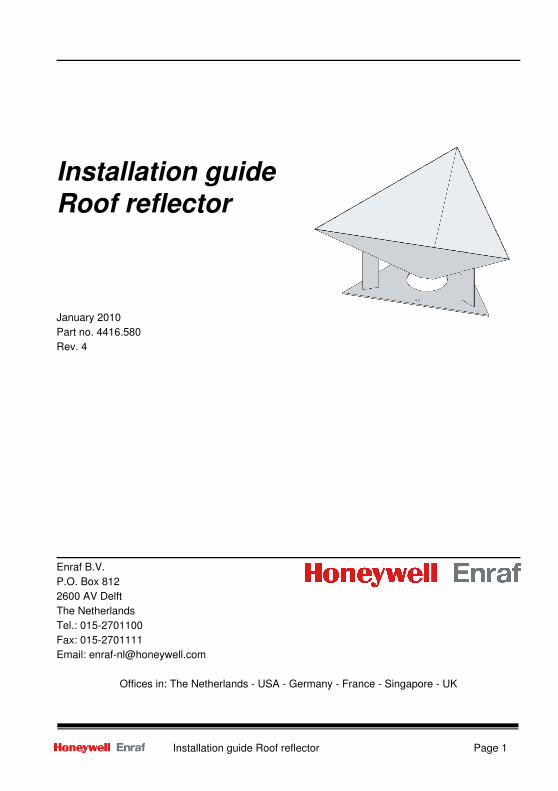
Installation guide
Roof reflector
January 2010
Part no. 4416.580
Rev. 4
Enraf B.V.
P.O. Box 812
2600 AV Delft
The Netherlands
Tel.: 015-2701100
Fax: 015-2701111
Email: [email protected]
Offices in: The Netherlands - USA - Germany - France - Singapore - UK
Table of Contents
Page 2 Installation guide Roof reflector
Table of Contents
1 Introduction................................................................................................................................4
1.1 General precautions ........................................................................................................4
2 Unpacking..................................................................................................................................5
2.1 Storage............................................................................................................................5
2.2 Inspection ........................................................................................................................5
3 Installation..................................................................................................................................6
3.1 Alignment of template......................................................................................................8
3.2 Determine holes for mounting blocks ..............................................................................8
3.3 Placing the mounting blocks............................................................................................9
3.4 Mounting Roof reflector ...................................................................................................9
3.5 Roof reflector glued on roof ...........................................................................................10
4 Related publications ................................................................................................................11
Preface
Installation guide Roof reflector Page 3
Preface
This installation guide describes the installation of the Enraf SmartRadar Roof reflector on inner
floating roof tanks.
For commissioning and service of the SmartRadar, please refer to the Installation guides of the
Antenna, Antenna Unit and Control Unit, and to the Instruction manual of the SmartRadar.
Refer also to the list of related publications in chapter 4.
Safety and prevention of damage
The technician must have basic technical knowledge to be able to safely install the equipment. It is
also required that when the SmartRadar and its reflector is installed in a hazardous area, the
technician works in accordance with the (local) requirements for electrical equipment in hazardous
areas.
“Warnings”, “Cautions”, and “Notes” have been used throughout the installation guide to bring
special matters to the immediate attention of the reader.
· A Warning concerns danger to the safety of the technician or user;
· A Caution draws the attention to an action which may damage the equipment;
· A Note points out a statement deserving more emphasis than the general text, but
does not deserve a “Warning” or “Caution”.
Legal aspects
The information in this installation guide is copyright property of Enraf B.V., The Netherlands.
Enraf B.V. disclaims any responsibility for personal injury or damage to the equipment caused by:
· Deviation from any of the prescribed procedures;
· Execution of activities that are not prescribed;
· Negligence of the general safety precautions for handling tools and use of
electricity.
Additional information
Please do not hesitate to contact Enraf B.V. or its representative if you require more
information.
Preface
Page 4 Installation guide Roof reflector
1 Introduction
The Enraf SmartRadar is a radar based level gauge.
The design of the SmartRadar is modular, consisting of the following three parts:
· Control Unit with local display;
· Antenna Unit with HF electronics;
· Antenna with tank separator and roof reflector.
For a more detailed description of the radar system configuration, refer to the Instruction manual
SmartRadar.
This installation guide describes the installation of the inner floating roof reflector.
On tanks with an internal floating roof and with a free space antenna, a roof reflector is required.
The roof reflector is installed on the internal floating roof below the antenna. Installation of the roof
reflector should be done prior to the antenna installation. The function of the roof reflector is to
ensure that signal is received by the antenna under all circumstances. Even in the case when the
roof is not horizontal during product movements.
1.1 General precautions
The entire installation procedure shall be in accordance with national, local and company
regulations.
Health aspect:
The emitted microwave energy is far below the accepted limits for exposure of the human
body to microwave radiation. Safety regulations state a maximum value of 5 - 8 mW/cm2 (IRPA
and ANSI guidelines).
Depending on the type of antenna, a maximum radiation of 0.03 mW/cm2 (with an 4" antenna)
to 0.008 mW/cm2 (with an 8" antenna) is generated.
Unpacking
Installation guide Roof reflector Page 5
2 Unpacking
2.1 Storage
There are no special requirements for storage of the reflector. Keep the reflector in its original
packing till it is used for installation.
2.2 Inspection
Inspect the package on arrival and notify the transporter or sales representative if there is any
damage. Don’t throw away the packing. It will be of use when further transport on site is needed.
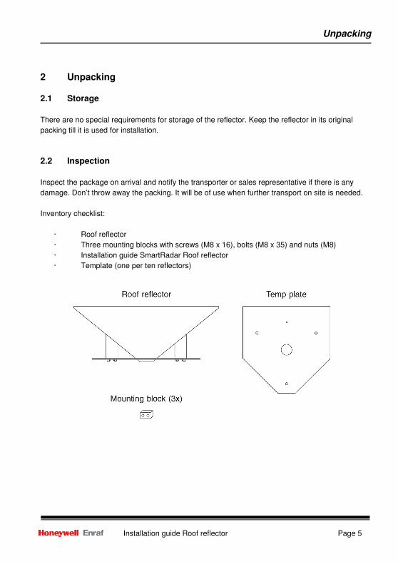
Inventory checklist:
· Roof reflector
· Three mounting blocks with screws (M8 x 16), bolts (M8 x 35) and nuts (M8)
· Installation guide SmartRadar Roof reflector
· Template (one per ten reflectors)
Installation
Page 6 Installation guide Roof reflector
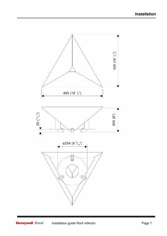
3 Installation
Installation of the Roof reflector requires access to the internal floating roof of the tank.
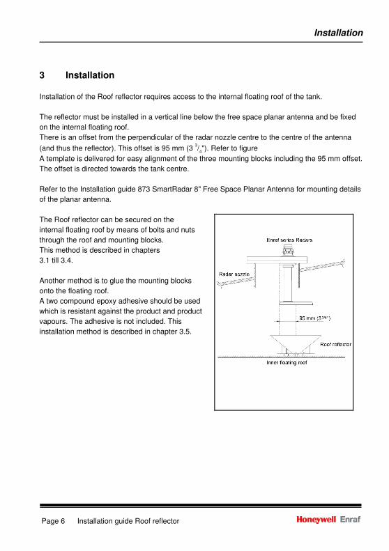
The reflector must be installed in a vertical line below the free space planar antenna and be fixed
on the internal floating roof.
There is an offset from the perpendicular of the radar nozzle centre to the centre of the antenna
(and thus the reflector). This offset is 95 mm (3 3/4"). Refer to figure
A template is delivered for easy alignment of the three mounting blocks including the 95 mm offset.
The offset is directed towards the tank centre.
Refer to the Installation guide 873 SmartRadar 8" Free Space Planar Antenna for mounting details
of the planar antenna.
The Roof reflector can be secured on the
internal floating roof by means of bolts and nuts
through the roof and mounting blocks.
This method is described in chapters
3.1 till 3.4.
Another method is to glue the mounting blocks
onto the floating roof.
A two compound epoxy adhesive should be used
which is resistant against the product and product
vapours. The adhesive is not included. This
installation method is described in chapter 3.5.
Installation
Installation guide Roof reflector Page 7
Installation
Page 8 Installation guide Roof reflector
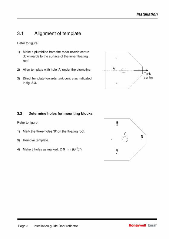
3.1 Alignment of template
Refer to figure
1) Make a plumbline from the radar nozzle centre
downwards to the surface of the inner floating
roof.
2) Align template with hole ‘A’ under the plumbline.
3) Direct template towards tank centre as indicated
in fig. 3.3.
3.2 Determine holes for mounting blocks
Refer to figure
1) Mark the three holes ‘B’ on the floating roof.
3) Remove template.
4) Make 3 holes as marked: Ø 9 mm (Ø 3/8").
Installation
Installation guide Roof reflector Page 9
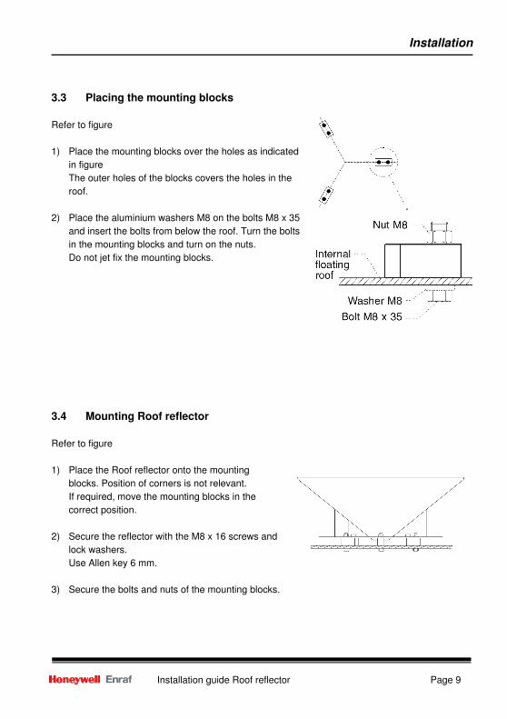
3.3 Placing the mounting blocks
Refer to figure
1) Place the mounting blocks over the holes as indicated
in figure
The outer holes of the blocks covers the holes in the
roof.
2) Place the aluminium washers M8 on the bolts M8 x 35
and insert the bolts from below the roof. Turn the bolts
in the mounting blocks and turn on the nuts.
Do not jet fix the mounting blocks.
3.4 Mounting Roof reflector
Refer to figure
1) Place the Roof reflector onto the mounting
blocks. Position of corners is not relevant.
If required, move the mounting blocks in the
correct position.
2) Secure the reflector with the M8 x 16 screws and
lock washers.
Use Allen key 6 mm.
3) Secure the bolts and nuts of the mounting blocks.
Installation
Page 10 Installation guide Roof reflector
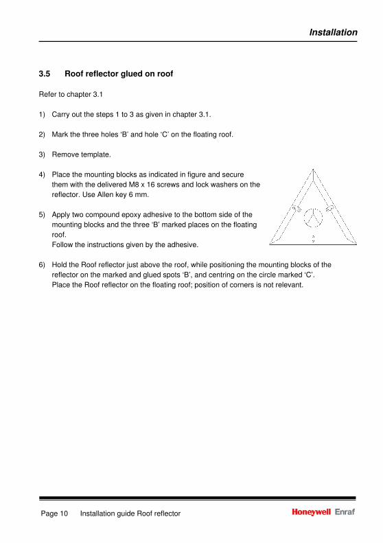
3.5 Roof reflector glued on roof
Refer to chapter 3.1
1) Carry out the steps 1 to 3 as given in chapter 3.1.
2) Mark the three holes ‘B’ and hole ‘C’ on the floating roof.
3) Remove template.
4) Place the mounting blocks as indicated in figure and secure
them with the delivered M8 x 16 screws and lock washers on the
reflector. Use Allen key 6 mm.
5) Apply two compound epoxy adhesive to the bottom side of the
mounting blocks and the three ‘B’ marked places on the floating
roof.
Follow the instructions given by the adhesive.
6) Hold the Roof reflector just above the roof, while positioning the mounting blocks of the
reflector on the marked and glued spots ‘B’, and centring on the circle marked ‘C’.
Place the Roof reflector on the floating roof; position of corners is not relevant.
Related publications
Installation guide Roof reflector Page 11
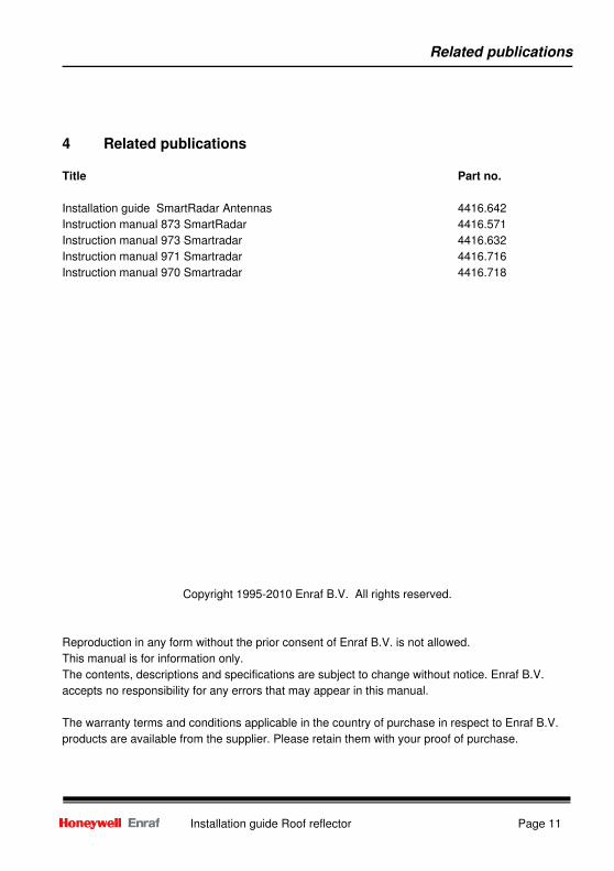
4 Related publications
Title Part no.
Installation guide SmartRadar Antennas 4416.642
Instruction manual 873 SmartRadar 4416.571
Instruction manual 973 Smartradar 4416.632
Instruction manual 971 Smartradar 4416.716
Instruction manual 970 Smartradar 4416.718
Copyright 1995-2010 Enraf B.V. All rights reserved.
Reproduction in any form without the prior consent of Enraf B.V. is not allowed.
This manual is for information only.
The contents, descriptions and specifications are subject to change without notice. Enraf B.V.
accepts no responsibility for any errors that may appear in this manual.
The warranty terms and conditions applicable in the country of purchase in respect to Enraf B.V.
products are available from the supplier. Please retain them with your proof of purchase.
Page 12 Installation guide Roof reflector
Delftechpark 39 2628 XJ Delft Tel. :+31 15 2701 100 E-mail : [email protected] Webiste: www.honeywellenraf.com PO Box 812 2600 AV Delft The Netherlands We at Honeywell Enraf are committed to excellence. Information in this publication is subject to change without notice
Enraf is a registered trade mark. Enraf B.V. Netherlands.