Embed Size (px)
Citation preview
Installation GuidePMWT-660/680 Projector Wall Mount for the
SMART Board™ Interactive Whiteboard
Trademark NoticeSMART Board, smarttech and the SMART logo are trademarks or registered trademarks of SMART Technologies ULC in the U.S. and/or other countries. TORX is a trademark of Textron Inc. Phillips is a registered trademark of Phillips Screw Company. NEC is a trademark of NEC Corporation. All other third-party product and company names may be trademarks of their respective owners. Patent No. US5448263; US6141000; US6326954; US6337681; US6540366; US6741267; US6747636; US7151533; US7289113; and CA2058219. Other patents pending.
Copyright Notice© 1995–2008 SMART Technologies ULC. All rights reserved. No part of this publication may be reproduced, transmitted, transcribed, stored in a retrieval system or translated into any language in any form by any means without the prior written consent of SMART Technologies ULC. Information in this manual is subject to change without notice and does not represent a commitment on the part of SMART.
Printed in Canada 05/2008
Product Registration
If you register your SMART product, we’ll notify you of new features and software upgrades.
Register online at www.smarttech.com/registration.
Keep the following information available, in case you need to contact Technical Support:
Serial Number ____________________________________________
Date of Purchase _________________________________________
Installation Overview
Please read these instructions carefully before you install your projector wall mount.
Use this guide to assemble and install the projector wall mount for SMART Board™ interactive whiteboards, which is a projector mount for your SMART Board interactive whiteboard (models 660 or 680) and an NEC WT600 or WT610 projector (purchased separately). The SMART Board 660 interactive whiteboard is 64" (162.6 cm) measured diagonally, and the 680 measures 77" (195.6 cm). PMWT-660, PMWT-680
You can use this guide if you’re installing the projector wall mount on a standard drywall, concrete or cinder block wall. If you have any other material cladding your wall (such as brick and masonry), consult professionals with the appropriate expertise.
The 660 weighs approximately 51 1/2 lb. (23.4 kg) when combined with the projector mount and projector. The 680, when combined with the projector mount and the projector, weighs approximately 53 1/2 lb. (24.3 kg). Before installing, make sure the wall can support such weight.
A qualified service technician and an assistant should install the projector mount. For example:
• your SMART reseller
• a SMART technical support staff member
• a qualified member of your staff who’s familiar with the structure of the room and the procedures for mounting objects on the particular type of wall (e.g., drywall, concrete or cinder block)
WARNING The projector wall mount works only with an NEC WT600 or WT610 projector. Any other weight hung from the projector support may cause the support to bend or break, which can injure anyone beneath it.
IMPORTANT If you’re installing the projector mount for a 660, the ceiling should be at least 8'4" (2.54 m) high. If you’re installing the projector mount for a 680, the ceiling should be at least 9'1" (2.76 m) high. If the ceiling doesn’t meet these requirements, the interactive whiteboard’s pen tray will be below the recommended height.
IMPORTANTDon’t install the interactive whiteboard on an unsupported wall, because the mount may vibrate and interfere with the interactive whiteboard’s orientation when you write on the screen.
PMWT-660/680 Installation Guide 1
Ap50siz
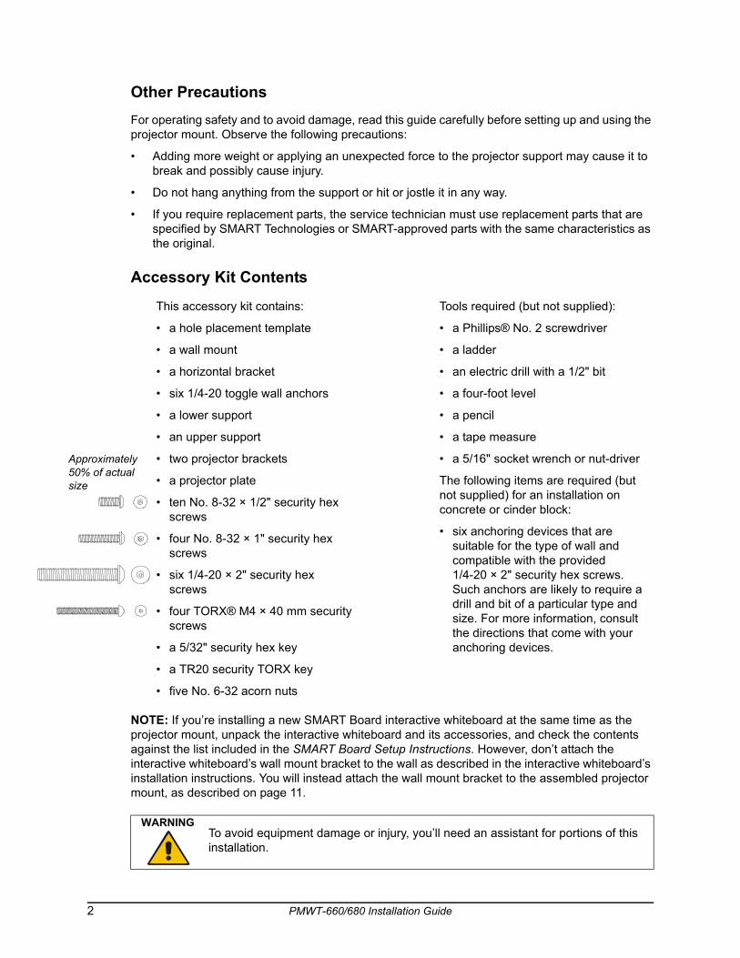
Other PrecautionsFor operating safety and to avoid damage, read this guide carefully before setting up and using the projector mount. Observe the following precautions:
• Adding more weight or applying an unexpected force to the projector support may cause it to break and possibly cause injury.
• Do not hang anything from the support or hit or jostle it in any way.
• If you require replacement parts, the service technician must use replacement parts that are specified by SMART Technologies or SMART-approved parts with the same characteristics as the original.
Accessory Kit Contents
NOTE: If you’re installing a new SMART Board interactive whiteboard at the same time as the projector mount, unpack the interactive whiteboard and its accessories, and check the contents against the list included in the SMART Board Setup Instructions. However, don’t attach the interactive whiteboard’s wall mount bracket to the wall as described in the interactive whiteboard’s installation instructions. You will instead attach the wall mount bracket to the assembled projector mount, as described on page 11.
This accessory kit contains:
• a hole placement template
• a wall mount
• a horizontal bracket
• six 1/4-20 toggle wall anchors
• a lower support
• an upper support
• two projector brackets
• a projector plate
• ten No. 8-32 × 1/2" security hex screws
• four No. 8-32 × 1" security hex screws
• six 1/4-20 × 2" security hex screws
• four TORX® M4 × 40 mm security screws
• a 5/32" security hex key
• a TR20 security TORX key
• five No. 6-32 acorn nuts
Tools required (but not supplied):
• a Phillips® No. 2 screwdriver
• a ladder
• an electric drill with a 1/2" bit
• a four-foot level
• a pencil
• a tape measure
• a 5/16" socket wrench or nut-driver
The following items are required (but not supplied) for an installation on concrete or cinder block:
• six anchoring devices that are suitable for the type of wall and compatible with the provided 1/4-20 × 2" security hex screws. Such anchors are likely to require a drill and bit of a particular type and size. For more information, consult the directions that come with your anchoring devices.
WARNINGTo avoid equipment damage or injury, you’ll need an assistant for portions of this installation.
proximately % of actual e
2 PMWT-660/680 Installation Guide
To install the projector wall mount, you must complete the following tasks:
1. Find a suitable location for the projector wall mount (page 4).
2. Install the wall mounting hardware (pages 4 and 5).
3. Assemble and mount the projector support (page 7).
4. Attach the projector plate to the projector (page 11).
5. Attach the projector to the projector support (page 12).
6. Hang the interactive whiteboard (page 13).
7. Route the projector cables (page 15).
8. Adjust the projected image on the interactive whiteboard (page 16).
If you’re installing the projector mount above an existing SMART Board interactive whiteboard, you must first remove the interactive whiteboard. Follow the instructions in this guide to install the projector mount and reinstall the SMART Board interactive whiteboard.
1. Disconnect the SMART Board interactive whiteboard from the computer.
2. Remove the pens and eraser from the pen tray.
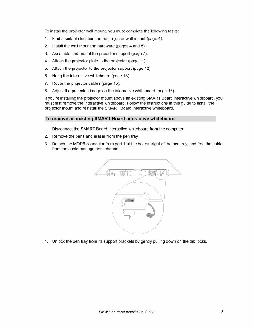
3. Detach the MOD6 connector from port 1 at the bottom-right of the pen tray, and free the cable from the cable management channel.
4. Unlock the pen tray from its support brackets by gently pulling down on the tab locks.
To remove an existing SMART Board interactive whiteboard
PMWT-660/680 Installation Guide 3
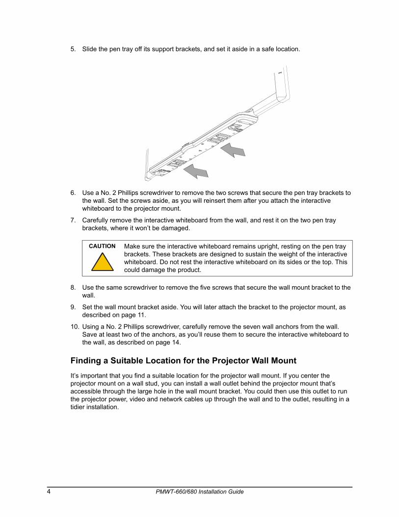
5. Slide the pen tray off its support brackets, and set it aside in a safe location.
6. Use a No. 2 Phillips screwdriver to remove the two screws that secure the pen tray brackets to the wall. Set the screws aside, as you will reinsert them after you attach the interactive whiteboard to the projector mount.
7. Carefully remove the interactive whiteboard from the wall, and rest it on the two pen tray brackets, where it won’t be damaged.
8. Use the same screwdriver to remove the five screws that secure the wall mount bracket to the wall.
9. Set the wall mount bracket aside. You will later attach the bracket to the projector mount, as described on page 11.
10. Using a No. 2 Phillips screwdriver, carefully remove the seven wall anchors from the wall. Save at least two of the anchors, as you’ll reuse them to secure the interactive whiteboard to the wall, as described on page 14.
Finding a Suitable Location for the Projector Wall MountIt’s important that you find a suitable location for the projector wall mount. If you center the projector mount on a wall stud, you can install a wall outlet behind the projector mount that’s accessible through the large hole in the wall mount bracket. You could then use this outlet to run the projector power, video and network cables up through the wall and to the outlet, resulting in a tidier installation.
CAUTION Make sure the interactive whiteboard remains upright, resting on the pen tray brackets. These brackets are designed to sustain the weight of the interactive whiteboard. Do not rest the interactive whiteboard on its sides or the top. This could damage the product.
4 PMWT-660/680 Installation Guide
In the absence of such an outlet, you must route the projector cables through the projector mount and behind the interactive whiteboard, as described on page 16.
Installing the Wall Mounting Hardware in Drywall1. Using the provided template, mark the anchor hole locations with a pencil. Use a four-foot
level to verify that the template is level.
If you would like to install the interactive whiteboard at the recommended installation height, make sure the lowest anchor holes are at least:
– 72 3/4" (184.8 cm) from the floor, if you’re installing a 660
– 80 3/4" (205.1 cm) from the floor, if you’re installing a 680
If the room’s ceiling is lower than recommended (see the Important Note above), you must measure down from the ceiling rather than up from the floor. This guarantees that there’s enough clearance between the projector mount and the ceiling. Make sure the highest anchor holes are at least:
– 4" (10.2 cm) from the ceiling, if you’re installing a 660
– 5" (12.7 cm) from the ceiling, if you’re installing a 680
2. Using an electric drill with a 1/2" bit, drill holes in the drywall at the six anchor hole locations that you marked in the previous step.
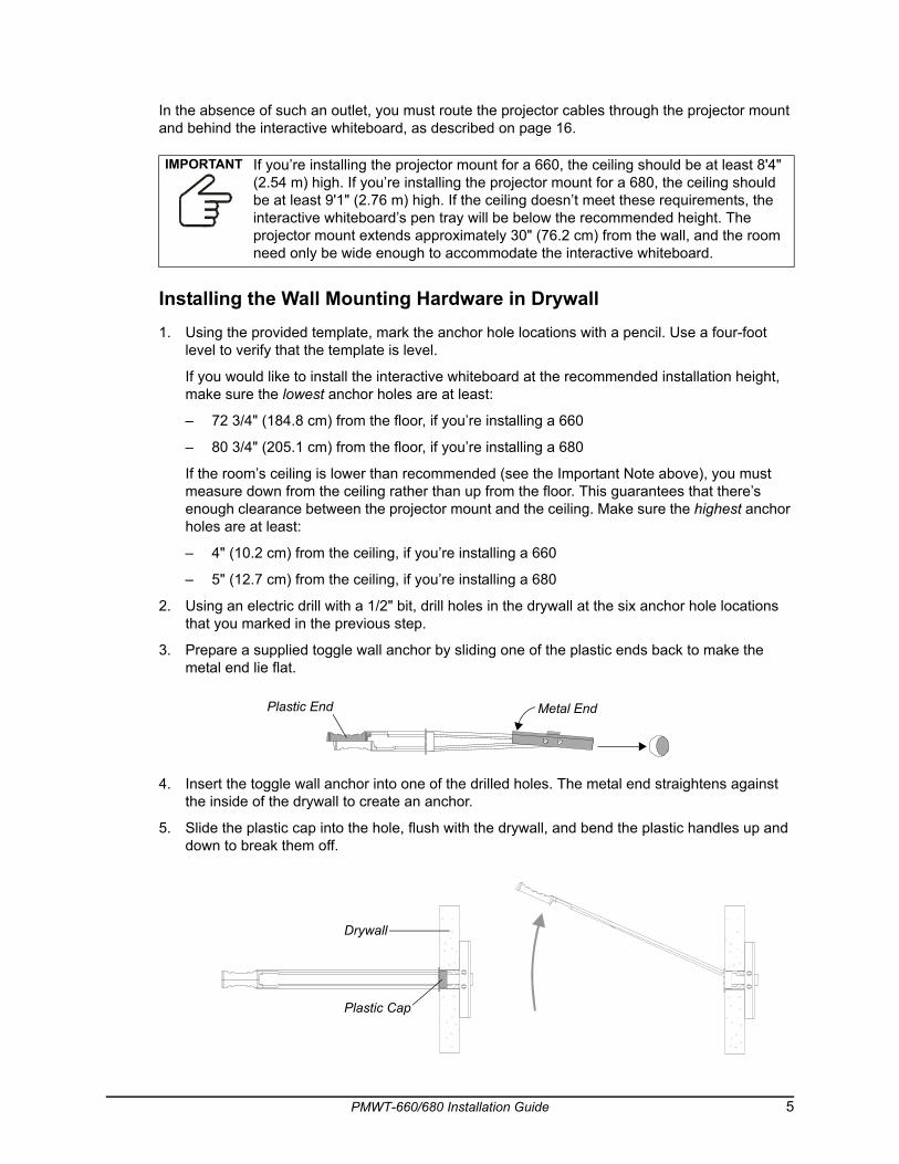
3. Prepare a supplied toggle wall anchor by sliding one of the plastic ends back to make the metal end lie flat.
4. Insert the toggle wall anchor into one of the drilled holes. The metal end straightens against the inside of the drywall to create an anchor.
5. Slide the plastic cap into the hole, flush with the drywall, and bend the plastic handles up and down to break them off.
IMPORTANT If you’re installing the projector mount for a 660, the ceiling should be at least 8'4" (2.54 m) high. If you’re installing the projector mount for a 680, the ceiling should be at least 9'1" (2.76 m) high. If the ceiling doesn’t meet these requirements, the interactive whiteboard’s pen tray will be below the recommended height. The projector mount extends approximately 30" (76.2 cm) from the wall, and the room need only be wide enough to accommodate the interactive whiteboard.
Plastic End Metal End
Drywall
Plastic Cap
PMWT-660/680 Installation Guide 5
6. Repeat this procedure for the remaining five anchor holes.
7. Thread one of the supplied 1/4-20 × 2" security hex screws into the upper right wall anchor by hand until the screw protrudes 1/4" (6 mm) from the wall.
8. Repeat this procedure for the upper left, lower left and lower right anchors. Leave the remaining two anchors vacant for now.
Installing the Wall Mounting Hardware in Concrete or Cinder Block
1. Using the provided template, mark the anchor hole locations with a pencil. Use a four-foot level to verify that the template is level.
If you would like to install the interactive whiteboard at the recommended installation height, make sure the lowest anchor holes are at least:
– 72 3/4" (184.8 cm) from the floor, if you’re installing a 660
– 80 3/4" (205.1 cm) from the floor, if you’re installing a 680
If the room’s ceiling is lower than recommended (see the Important Note on page 5), you must measure down from the ceiling rather than up from the floor. This guarantees that there’s enough clearance between the projector mount and the ceiling. Make sure the highest anchor holes are at least:
– 4" (10.2 cm) from the ceiling, if you’re installing a 660
– 5" (12.7 cm) from the ceiling, if you’re installing a 680
2. Following the instructions that came with the anchoring devices, install the anchors at the six anchor hole locations that you marked in the previous step.
3. Partially thread one of the supplied 1/4-20 × 2" security hex screws into the upper right anchor, leaving 1/4" (6 mm) protruding from the wall.
4. Repeat this procedure for the upper left, lower left and lower right anchors. Leave the remaining two anchors vacant for now.
IMPORTANTA qualified technician should complete the following procedure. The technician must be familiar with the structure of the room and the procedures for mounting objects on the particular type of wall.
6 PMWT-660/680 Installation Guide
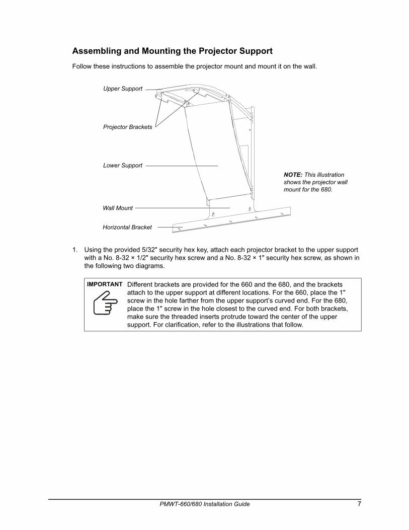
Assembling and Mounting the Projector SupportFollow these instructions to assemble the projector mount and mount it on the wall.
1. Using the provided 5/32" security hex key, attach each projector bracket to the upper support with a No. 8-32 × 1/2" security hex screw and a No. 8-32 × 1" security hex screw, as shown in the following two diagrams.
IMPORTANT Different brackets are provided for the 660 and the 680, and the brackets attach to the upper support at different locations. For the 660, place the 1" screw in the hole farther from the upper support’s curved end. For the 680, place the 1" screw in the hole closest to the curved end. For both brackets, make sure the threaded inserts protrude toward the center of the upper support. For clarification, refer to the illustrations that follow.
Upper Support
Lower Support
Projector Brackets
Wall Mount
NOTE: This illustration shows the projector wall mount for the 680.
Horizontal Bracket
PMWT-660/680 Installation Guide 7
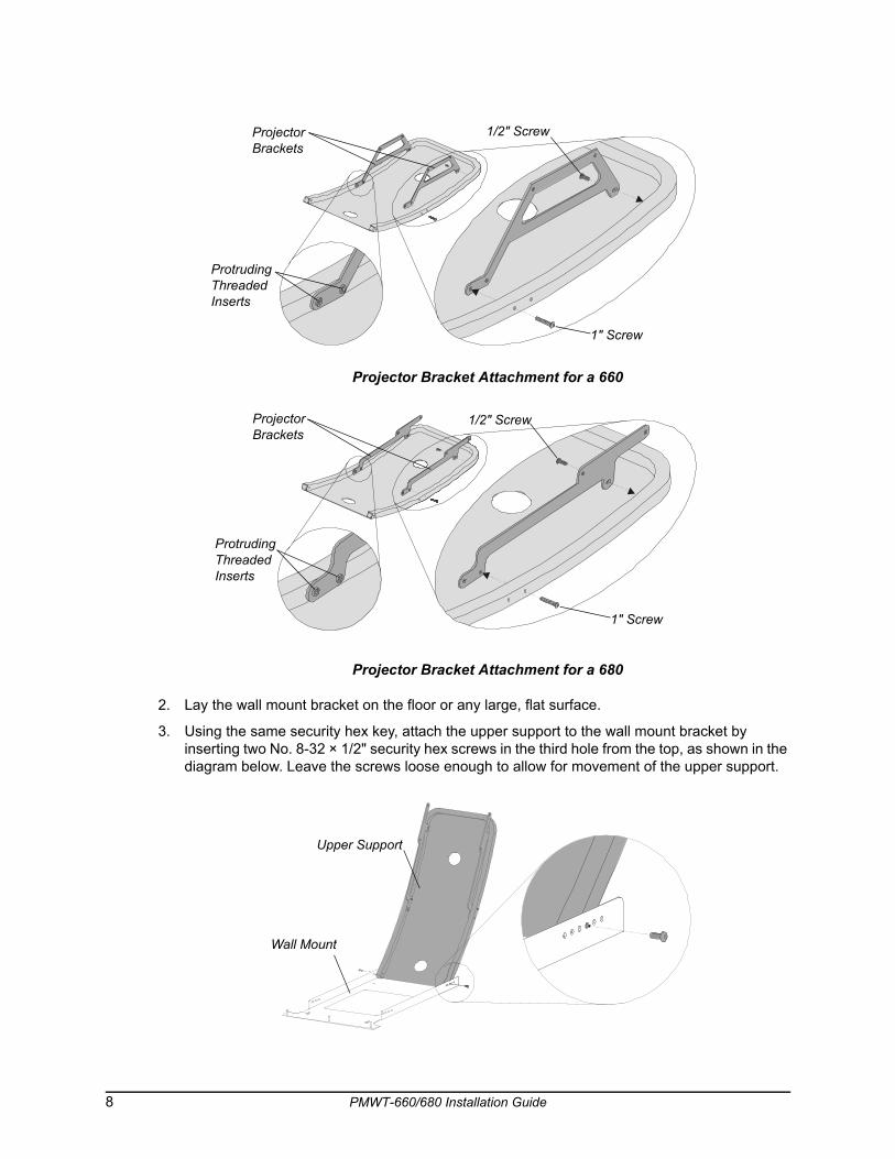
Projector Bracket Attachment for a 660
Projector Bracket Attachment for a 680
2. Lay the wall mount bracket on the floor or any large, flat surface.
3. Using the same security hex key, attach the upper support to the wall mount bracket by inserting two No. 8-32 × 1/2" security hex screws in the third hole from the top, as shown in the diagram below. Leave the screws loose enough to allow for movement of the upper support.
ProtrudingThreaded Inserts
ProjectorBrackets
1/2" Screw
1" Screw
ProtrudingThreaded Inserts
ProjectorBrackets
1/2" Screw
1" Screw
Upper Support
Wall Mount
8 PMWT-660/680 Installation Guide
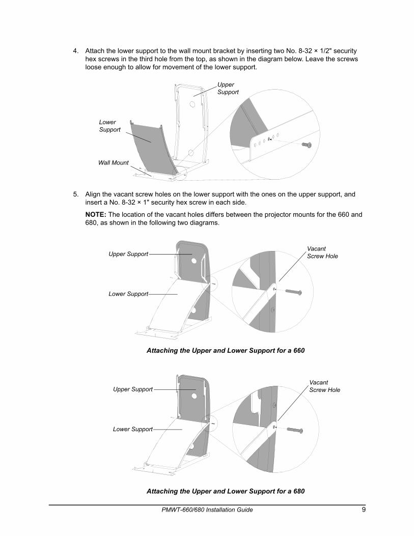
4. Attach the lower support to the wall mount bracket by inserting two No. 8-32 × 1/2" security hex screws in the third hole from the top, as shown in the diagram below. Leave the screws loose enough to allow for movement of the lower support.
5. Align the vacant screw holes on the lower support with the ones on the upper support, and insert a No. 8-32 × 1" security hex screw in each side.
NOTE: The location of the vacant holes differs between the projector mounts for the 660 and 680, as shown in the following two diagrams.
Attaching the Upper and Lower Support for a 660
Attaching the Upper and Lower Support for a 680
Wall Mount
Lower Support
Upper Support
Vacant Screw HoleUpper Support
Lower Support
Vacant Screw Hole
Lower Support
Upper Support
PMWT-660/680 Installation Guide 9
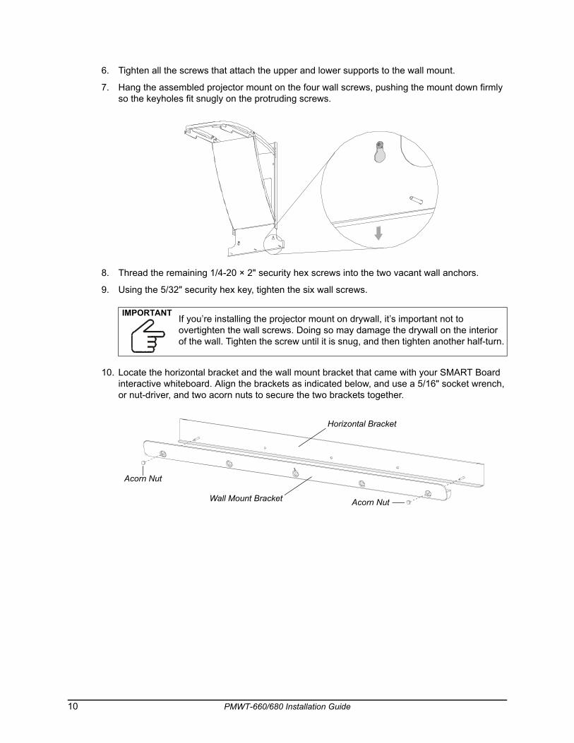
6. Tighten all the screws that attach the upper and lower supports to the wall mount.
7. Hang the assembled projector mount on the four wall screws, pushing the mount down firmly so the keyholes fit snugly on the protruding screws.
8. Thread the remaining 1/4-20 × 2" security hex screws into the two vacant wall anchors.
9. Using the 5/32" security hex key, tighten the six wall screws.
10. Locate the horizontal bracket and the wall mount bracket that came with your SMART Board interactive whiteboard. Align the brackets as indicated below, and use a 5/16" socket wrench, or nut-driver, and two acorn nuts to secure the two brackets together.
IMPORTANTIf you’re installing the projector mount on drywall, it’s important not to overtighten the wall screws. Doing so may damage the drywall on the interior of the wall. Tighten the screw until it is snug, and then tighten another half-turn.
Acorn Nut
Wall Mount Bracket Acorn Nut
Horizontal Bracket
10 PMWT-660/680 Installation Guide
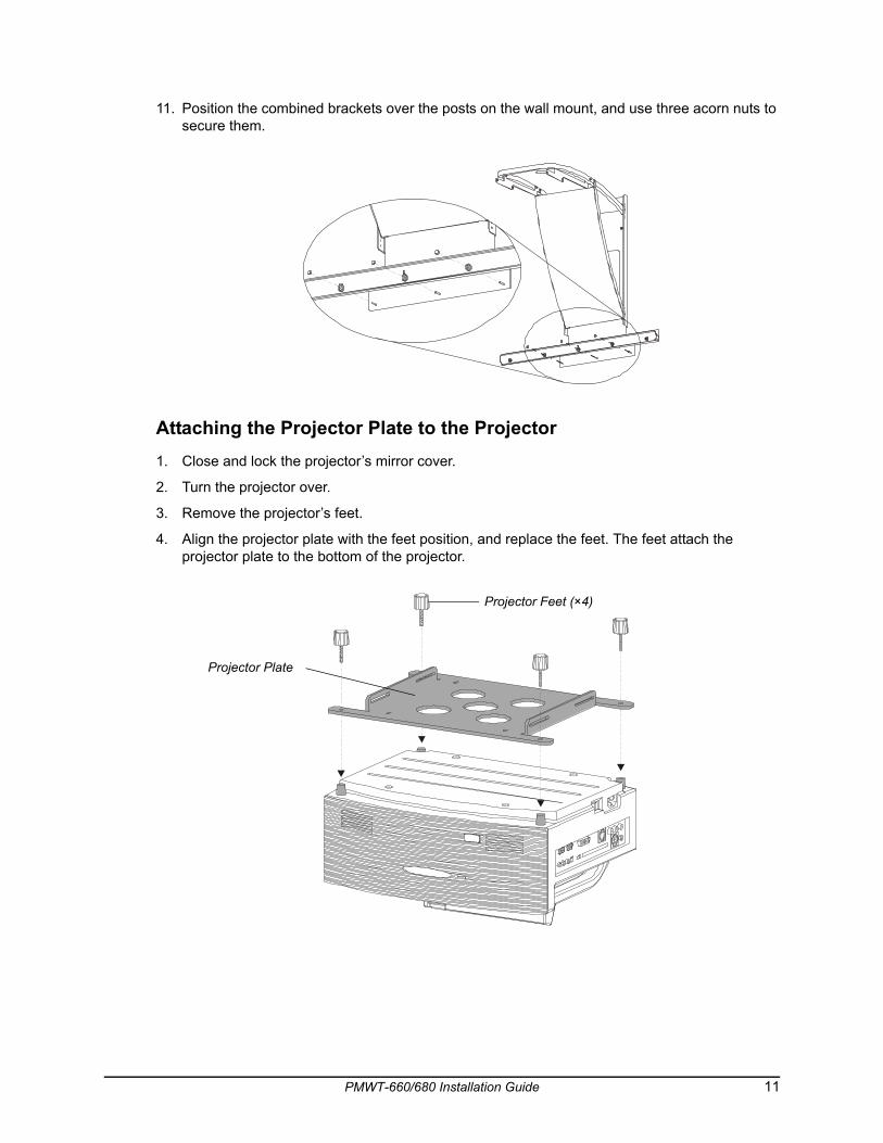
11. Position the combined brackets over the posts on the wall mount, and use three acorn nuts to secure them.
Attaching the Projector Plate to the Projector1. Close and lock the projector’s mirror cover.
2. Turn the projector over.
3. Remove the projector’s feet.
4. Align the projector plate with the feet position, and replace the feet. The feet attach the projector plate to the bottom of the projector.
Projector Plate
Projector Feet (×4)
PMWT-660/680 Installation Guide 11
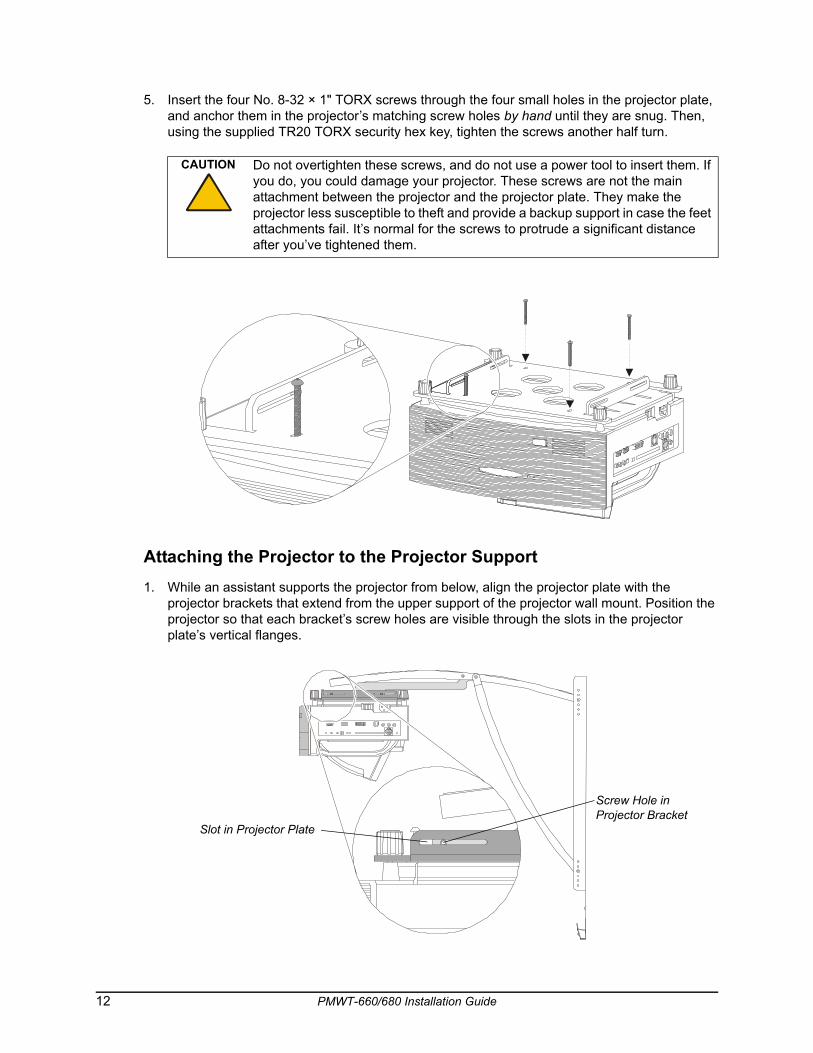
5. Insert the four No. 8-32 × 1" TORX screws through the four small holes in the projector plate, and anchor them in the projector’s matching screw holes by hand until they are snug. Then, using the supplied TR20 TORX security hex key, tighten the screws another half turn.
Attaching the Projector to the Projector Support1. While an assistant supports the projector from below, align the projector plate with the
projector brackets that extend from the upper support of the projector wall mount. Position the projector so that each bracket’s screw holes are visible through the slots in the projector plate’s vertical flanges.
CAUTION Do not overtighten these screws, and do not use a power tool to insert them. If you do, you could damage your projector. These screws are not the main attachment between the projector and the projector plate. They make the projector less susceptible to theft and provide a backup support in case the feet attachments fail. It’s normal for the screws to protrude a significant distance after you’ve tightened them.
Slot in Projector Plate
Screw Hole in Projector Bracket
12 PMWT-660/680 Installation Guide
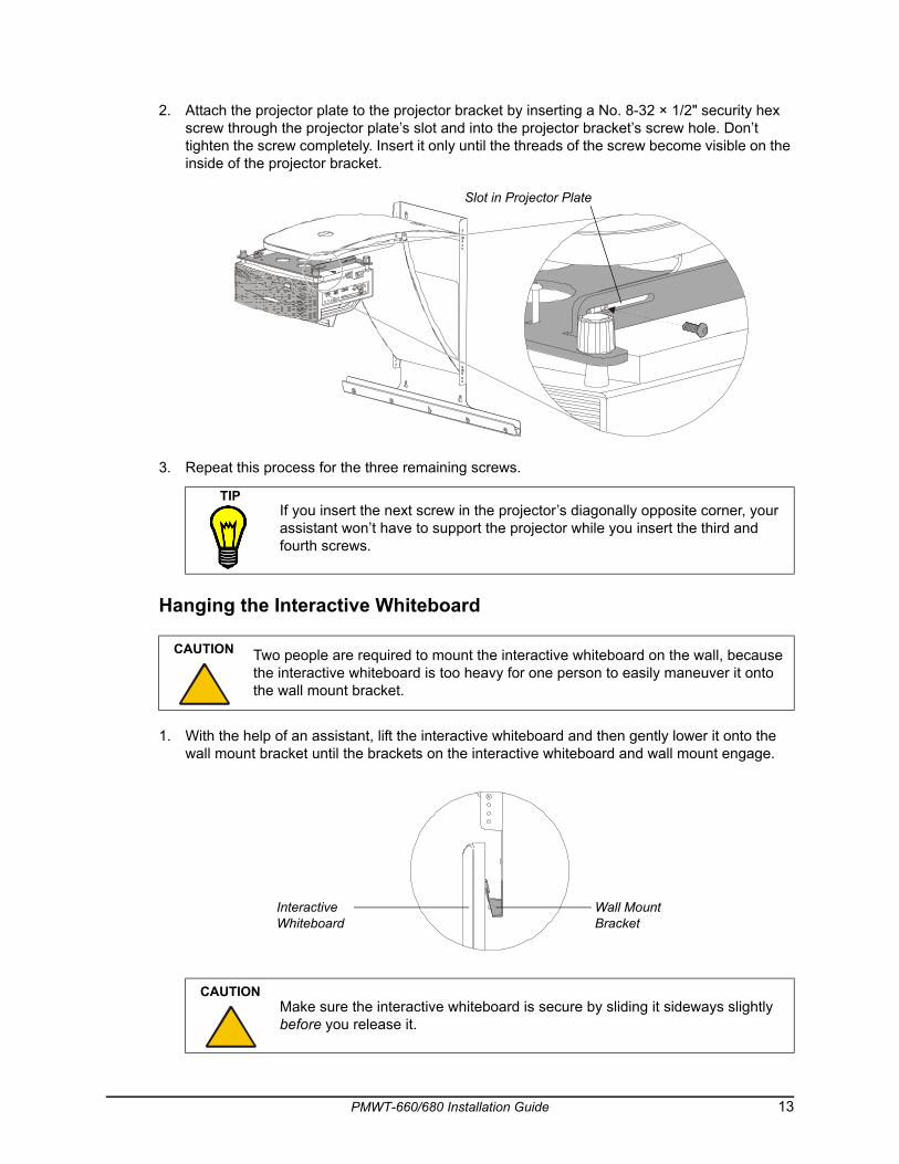
2. Attach the projector plate to the projector bracket by inserting a No. 8-32 × 1/2" security hex screw through the projector plate’s slot and into the projector bracket’s screw hole. Don’t tighten the screw completely. Insert it only until the threads of the screw become visible on the inside of the projector bracket.
3. Repeat this process for the three remaining screws.
Hanging the Interactive Whiteboard
1. With the help of an assistant, lift the interactive whiteboard and then gently lower it onto the wall mount bracket until the brackets on the interactive whiteboard and wall mount engage.
TIPIf you insert the next screw in the projector’s diagonally opposite corner, your assistant won’t have to support the projector while you insert the third and fourth screws.
CAUTION Two people are required to mount the interactive whiteboard on the wall, because the interactive whiteboard is too heavy for one person to easily maneuver it onto the wall mount bracket.
CAUTIONMake sure the interactive whiteboard is secure by sliding it sideways slightly before you release it.
Slot in Projector Plate
Interactive Whiteboard
Wall Mount Bracket
PMWT-660/680 Installation Guide 13
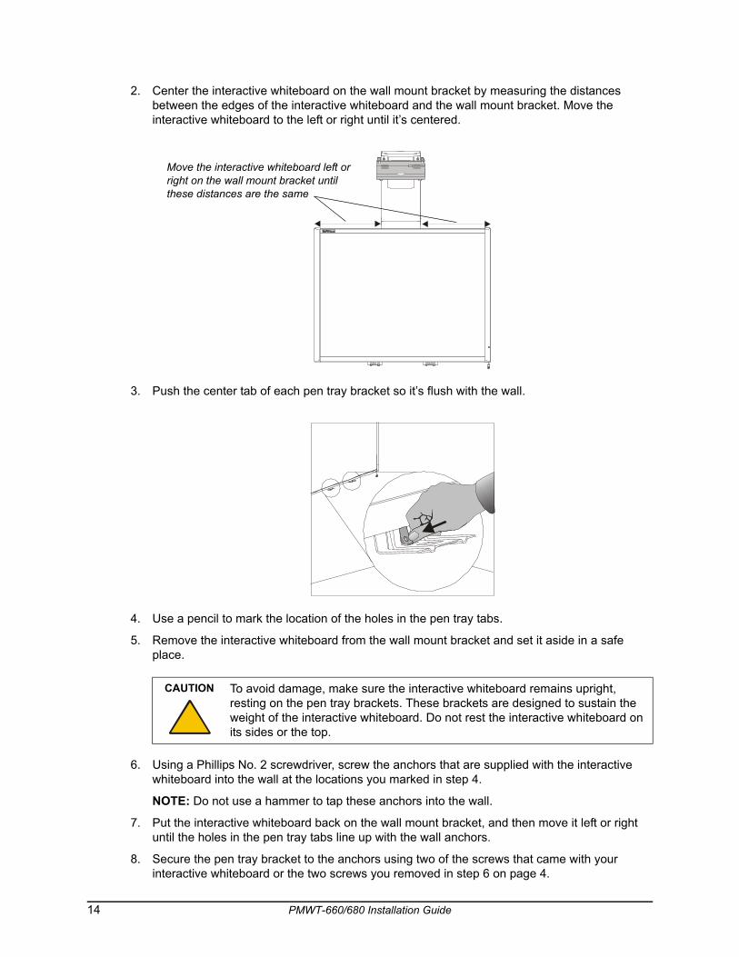
2. Center the interactive whiteboard on the wall mount bracket by measuring the distances between the edges of the interactive whiteboard and the wall mount bracket. Move the interactive whiteboard to the left or right until it’s centered.
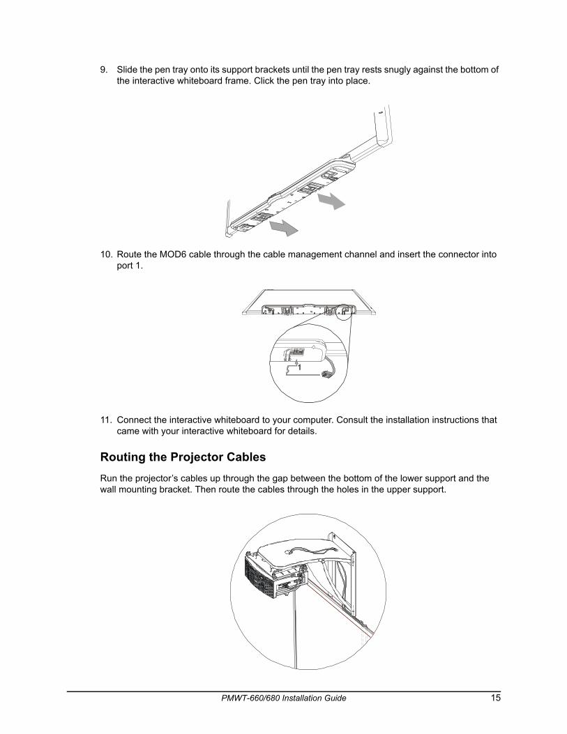
3. Push the center tab of each pen tray bracket so it’s flush with the wall.
4. Use a pencil to mark the location of the holes in the pen tray tabs.
5. Remove the interactive whiteboard from the wall mount bracket and set it aside in a safe place.
6. Using a Phillips No. 2 screwdriver, screw the anchors that are supplied with the interactive whiteboard into the wall at the locations you marked in step 4.
NOTE: Do not use a hammer to tap these anchors into the wall.
7. Put the interactive whiteboard back on the wall mount bracket, and then move it left or right until the holes in the pen tray tabs line up with the wall anchors.
8. Secure the pen tray bracket to the anchors using two of the screws that came with your interactive whiteboard or the two screws you removed in step 6 on page 4.
CAUTION To avoid damage, make sure the interactive whiteboard remains upright, resting on the pen tray brackets. These brackets are designed to sustain the weight of the interactive whiteboard. Do not rest the interactive whiteboard on its sides or the top.
Move the interactive whiteboard left or right on the wall mount bracket until these distances are the same
14 PMWT-660/680 Installation Guide
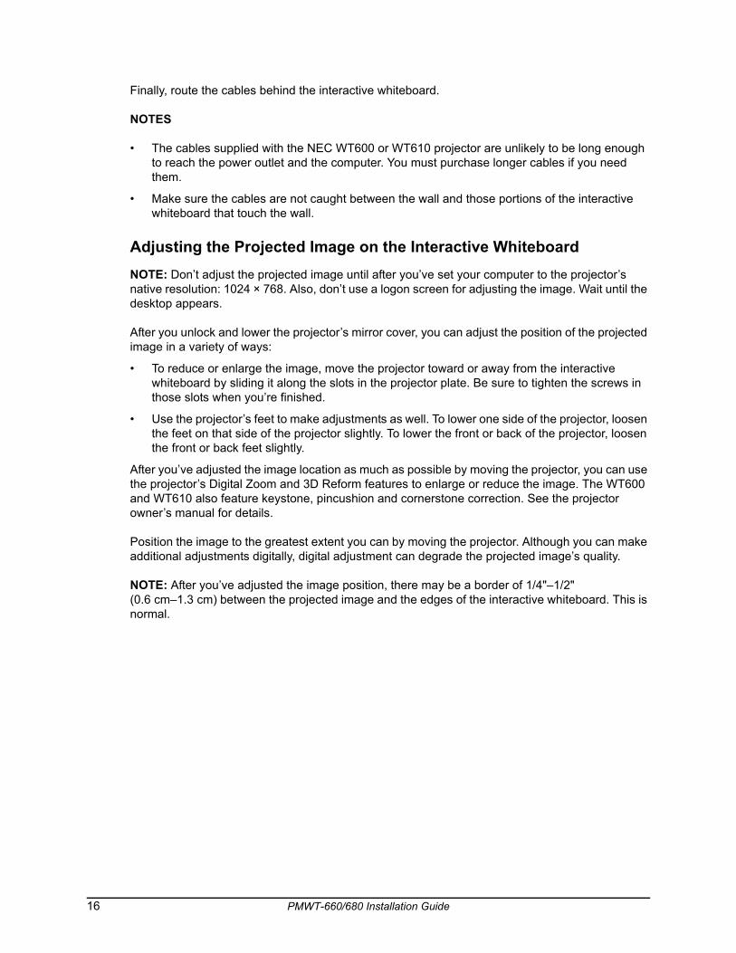
9. Slide the pen tray onto its support brackets until the pen tray rests snugly against the bottom of the interactive whiteboard frame. Click the pen tray into place.
10. Route the MOD6 cable through the cable management channel and insert the connector into port 1.
11. Connect the interactive whiteboard to your computer. Consult the installation instructions that came with your interactive whiteboard for details.
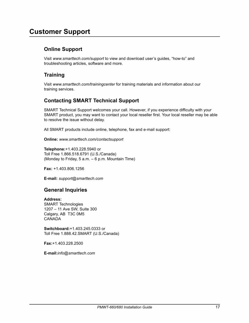
Routing the Projector CablesRun the projector’s cables up through the gap between the bottom of the lower support and the wall mounting bracket. Then route the cables through the holes in the upper support.
PMWT-660/680 Installation Guide 15
Finally, route the cables behind the interactive whiteboard.
NOTES
• The cables supplied with the NEC WT600 or WT610 projector are unlikely to be long enough to reach the power outlet and the computer. You must purchase longer cables if you need them.
• Make sure the cables are not caught between the wall and those portions of the interactive whiteboard that touch the wall.
Adjusting the Projected Image on the Interactive WhiteboardNOTE: Don’t adjust the projected image until after you’ve set your computer to the projector’s native resolution: 1024 × 768. Also, don’t use a logon screen for adjusting the image. Wait until the desktop appears.
After you unlock and lower the projector’s mirror cover, you can adjust the position of the projected image in a variety of ways:
• To reduce or enlarge the image, move the projector toward or away from the interactive whiteboard by sliding it along the slots in the projector plate. Be sure to tighten the screws in those slots when you’re finished.
• Use the projector’s feet to make adjustments as well. To lower one side of the projector, loosen the feet on that side of the projector slightly. To lower the front or back of the projector, loosen the front or back feet slightly.
After you’ve adjusted the image location as much as possible by moving the projector, you can use the projector’s Digital Zoom and 3D Reform features to enlarge or reduce the image. The WT600 and WT610 also feature keystone, pincushion and cornerstone correction. See the projector owner’s manual for details.
Position the image to the greatest extent you can by moving the projector. Although you can make additional adjustments digitally, digital adjustment can degrade the projected image’s quality.
NOTE: After you’ve adjusted the image position, there may be a border of 1/4"–1/2" (0.6 cm–1.3 cm) between the projected image and the edges of the interactive whiteboard. This is normal.
16 PMWT-660/680 Installation Guide
Customer Support
Online SupportVisit www.smarttech.com/support to view and download user’s guides, “how-to” and troubleshooting articles, software and more.
TrainingVisit www.smarttech.com/trainingcenter for training materials and information about our training services.
Contacting SMART Technical SupportSMART Technical Support welcomes your call. However, if you experience difficulty with your SMART product, you may want to contact your local reseller first. Your local reseller may be able to resolve the issue without delay.
All SMART products include online, telephone, fax and e-mail support:
Online: www.smarttech.com/contactsupport
Telephone:+1.403.228.5940 or Toll Free 1.866.518.6791 (U.S./Canada)(Monday to Friday, 5 a.m. – 6 p.m. Mountain Time)
Fax: +1.403.806.1256
E-mail: [email protected]
General InquiriesAddress:SMART Technologies1207 – 11 Ave SW, Suite 300Calgary, AB T3C 0M5CANADA
Switchboard:+1.403.245.0333 or Toll Free 1.888.42.SMART (U.S./Canada)
Fax:+1.403.228.2500
E-mail:[email protected]
PMWT-660/680 Installation Guide 17
WarrantyProduct warranty is governed by the terms and conditions of SMART’s “Limited Equipment Warranty” that shipped with the SMART product at the time of purchase.
RegistrationTo help us serve you, register online at www.smarttech.com/registration.
18 PMWT-660/680 Installation Guide

SMART Technologies1207 – 11 Avenue SW, Suite 300
Calgary, AB T3C 0M5
CANADA
www.smarttech.com/support
www.smarttech.com/contactsupport
Support +1.403.228.5940
Toll Free 1.866.518.6791 (U.S./Canada)
99-00545-01 REV B0


![EEHG - University of Strathclyde · 2020. 8. 21. · 680 700 720 R 56 µ m] 600 620 640 660 680 ... This work was supported by the US DOE Office of Basic Energy Sciences under award](https://img.pdfslide.us/doc/110x75/602caa1a4bbf31296310f349/eehg-university-of-strathclyde-2020-8-21-680-700-720-r-56-m-600-620-640.jpg)