Embed Size (px)
Citation preview

Installation Guide
DSA 2 MAXI Substation
1Danfoss District Energy VI.GE.K3.02 DEN-SMT/PL
1.0 Content ...................................................................................................................................................................................................................................12.0 Safety notes .............................................................................................................................................................................................................................23.0 System overview ....................................................................................................................................................................................................................2
3.1 General about district heating substations .............................................................................................................................................................23.2 DSA 2 MAXI Substation ...................................................................................................................................................................................................23.3 DSA 2 MAXI - example circuit diagram ......................................................................................................................................................................33.4 Electrical circuit diagrams ..............................................................................................................................................................................................4
4.0 Visible components in the substation ............................................................................................................................................................................85.0 Installation and start-up - Step by step ..........................................................................................................................................................................8
5.1 Removing the cover panels ...........................................................................................................................................................................................85.2 Protective cardboard cover ...........................................................................................................................................................................................95.3 Removing the substation from the pallet ................................................................................................................................................................95.4 Moving substation to the installation place ...........................................................................................................................................................95.5 Installation place ............................................................................................................................................................................................................ 105.6 Height adjustment ........................................................................................................................................................................................................ 115.7 Pipe connections ........................................................................................................................................................................................................... 11
5.7.1 Connection directions ..................................................................................................................................................................................... 115.7.2 Dimensions for the pipe connections ......................................................................................................................................................... 12
5.8 Electrification .................................................................................................................................................................................................................. 135.9 Controller settings ......................................................................................................................................................................................................... 13
5.9.1 Controller display and symbols ..................................................................................................................................................................... 145.9.2 Operating the controller .................................................................................................................................................................................. 145.9.3 Setting the date and time ................................................................................................................................................................................ 155.9.4 Setting the heat curve ...................................................................................................................................................................................... 165.9.5 Setting up limitations for flow temperature ............................................................................................................................................. 175.9.6 Manual control .................................................................................................................................................................................................... 185.9.7 Commissioning with one circuit ................................................................................................................................................................... 195.9.8 Sensor displays .................................................................................................................................................................................................... 205.9.9 Alarm ....................................................................................................................................................................................................................... 205.9.10 Changing the favourite display for the user ........................................................................................................................................... 225.9.11 Setting the room temperature .................................................................................................................................................................... 225.9.12 Setting domestic hot water temperature ............................................................................................................................................... 22
5.10 Basic parameters, factory settings .......................................................................................................................................................................... 235.11 Start-up ............................................................................................................................................................................................................................ 24
6.0 Trouble shooting ................................................................................................................................................................................................................. 24Declaration of conformity ....................................................................................................................................................................................................... 26
1.0 Content

Installation Guide DSA 2 MAXI Substation
2 DEN-SMT/PL VI.GE.K3.02 Danfoss District Energy
2.0 Safety notes
Read the instructions carefully before installation and start-up of the substation. Danfoss does not bear responsibility for whichever damages of device, which have not been mounted or stored in accordance with following instructions.
To avoid injury of persons and damages to the device, it is abso-lutely necessary to carefully read and observe these instructions.
Necessary assembly, start-up and maintenance work must be performed only by qualified and authorized personnel.
Warning of hot surfaceThe substation has got hot surfaces which can cause skin burns. Please be extremely cautious in close proximity of the substa-tion.
Warning of high pressure and temperatureThe maximum temperature and pressure always have to be checked on the product data label attached to the product.Be aware of the installation’s permissible system pressure and temperature. The risk of persons getting injured and equipment being damaged increases considerably if the recommended permissible operating parameters are exceeded.
The substation installation is equipped with safety valves which must always be mounted in accordance with local regulations.
Warning of transportation damagePrior to installing substation, please make sure that the substa-tion has not been damaged during transportation. Be extreme-ly careful when lifting or moving big and heavy substation.
3.0 System overview
3.1 General about district heating substations
The heating system of the property is connected to the district heating network with the substation. Hot district heating water in the district heating network runs through the heat exchangers in the substation. District heating water does not enter the internal network, just heat is transferred through the heat exchanger. The substation distributes heat into the heating and domestic hot water circuits.
All substation functions are controlled with an electronic con-troller. The outdoor temperature is measured and the controller adjusts the flow temperature to keep the room and domestic hot water temperatures in the desired level. With the controller you can change the property related settings (e.g. heating curve, temperature limits), check the temperatures, change the settings, create schedules etc.
3.2 DSA 2 MAXI Substation
Up to a certain point DSA 2 MAXI substation is standardized. The final selection of components and the dimensioning of the heat exchangers is done based on the requirements given by the customer. This Installation Guide includes general instructions. The more detailed information of the order can be found in the product related documentation.
District heating energy plant
Hot district heating water
Cool district heating water
District heating customer
Domestic hot water
Heating
Picture Energiateollisuus ry

Installation Guide DSA 2 MAXI Substation
33Danfoss District Energy VI.GE.K3.02 DEN-SMT/PL
3.3 DSA 2 MAXI - example circuit diagram DSA 2 MAXI-I2B032-050-A150-MD-FI
- 2 circuits, circuit diagram example After heating connection: domestic hot water and heating
25
15
15
1528
64
467 627
27 27
26
5 78
1665
1166 18
27
27
18
13
13
12
7 612
3030
2929 77 46
7
7
25a
TE1A
TV1
TV2
TE1B
TE2C
TE2B
TE2A
P2
P1
PE2
7
SUMMERSHUT-OFF
Temperatures and alarms on the controller display
Limit of the prefabricated substation
Options
1 Plate heat exchanger HE 2 Plate heat exchanger DHW5 Strainer6 Non-return valve7 Ball valve8 Circulation pump HE11 Safety valve HE12 Safety valve DHW13 Thermometer15 Manometer16 Expansion vessel18 Drain valve25 Electronic Controller 25a Pump control bow26 Outdoor temperature sensor27 Temperature sensor28 Pressure sensor29 Actuator30 Control valve46 Balancing valve64 Circulation pump DHW65 Service valve66 Filling valve

Installation Guide DSA 2 MAXI Substation
4 DEN-SMT/PL VI.GE.K3.02 Danfoss District Energy
3.4 Electrical circuit diagrams
DSA 2 MAXI with ECL controller
HE pump alarm

Installation Guide DSA 2 MAXI Substation
55Danfoss District Energy VI.GE.K3.02 DEN-SMT/PL
3.4 Electrical circuit diagrams
DSA 2 MAXI with ECL controller

Installation Guide DSA 2 MAXI Substation
6 DEN-SMT/PL VI.GE.K3.02 Danfoss District Energy
3.4 Electrical circuit diagrams
DSA 2 MAXI without controller

Installation Guide DSA 2 MAXI Substation
77Danfoss District Energy VI.GE.K3.02 DEN-SMT/PL
3.4 Electrical circuit diagrams
DSA 2 MAXI without controller

Installation Guide DSA 2 MAXI Substation
8 DEN-SMT/PL VI.GE.K3.02 Danfoss District Energy
4.0 Visible components in the substation
1. All substation functions are controlled and the operational values are observed with the electronic controller.
2. Dial: navigation in the menus and changes in the operating values by following the controller display.
3. Display: all settings, temperature information and mode are found on the graphical display. Navigation in the menus and changes in the settings are done following the display.
4. With the installation feet you can adjust the substation posi-tion directly and on the correct height. The adjustments can be done up to 6 cm.
5. Connections to district heating, heating and domestic hot water networks.
6. The cover panels protect the components in the substation and add user safety. When installing or servicing the cover panels have to be removed.
5.0 Installation and start-up - Step by step
5.1 Removing the cover panels
The cover panels have to be removed before moving the substation to the installation place and installing it.
The panels are removed by lifting them up.1. First remove the white panels from the front and back.2. After that lift the grey panels.
The cover panels can be placed back on the substation when the substation is installed and ready for use. The panels are placed back in the opposite order when compared with taking them away.
1
4
5
6
23
112
2

Installation Guide DSA 2 MAXI Substation
99Danfoss District Energy VI.GE.K3.02 DEN-SMT/PL
5.2 Protective cardboard cover
Leave the cardboard cover on top of the substation during moving and installation.
5.3 Removing the substation from the pallet
The substation is screwed on the pallet with the attaching feet. Take off the screws pointed with arrows in the picture.
5.4 Moving substation to the installation place
DSA 2 MAXI substation can be moved to the installation place us-ing several different ways, depending on the installation place and how to get there.Plan the most convenient route to the installation place. Be aware not to break floor and wall surfaces, stairs, doorposts etc.The substation includes delicate components.
Do not hurt yourself or damage the substation when lifting it!
1. Moving with a pallet truck.

Installation Guide DSA 2 MAXI Substation
10 DEN-SMT/PL VI.GE.K3.02 Danfoss District Energy
2. Lifting with a crane It is possible to screw up lifting eyes in the top corners after remov-ing detachable metal round pieces from the roof. This way substa-tion can be lifted up by using straps.
5.5 Installation place
The installation place and the pipe connections for DSA 2 MAXI substation can be planned in beforehand due to standardized sizing.
The upwards oriented connections enable installation e.g. close to the wall. Since the hot surfaces are hidden underneath the cover it is possible to use the boiler room also for some other activities.

Installation Guide DSA 2 MAXI Substation
1111Danfoss District Energy VI.GE.K3.02 DEN-SMT/PL
5.6 Height adjustmentAdjust the substation straight horizontally and on the desired height with the help of the installation feet. By turning the adjust-ment feet you can make up to 6 cm adjustments.
5.7 Pipe connectionsThe substation is connected to the district heating network, heat-ing, domestic hot water and circulation networks in the building according to the connections and flow directions in the drawing.
The pipes equipped with the couplings are to be detached and welded somewhere else but above the substation.
The pipes must be mounted so that the strain caused by e.g. ther-mal expansion, does not harm the sustation. The pipes must be equipped with brackets in order to prevent any torsional stress.
The connection to the district heating network can be done only by a qualified installer accepted by the district heating distributor.
Prior to installation all pipes and connections have to be cleaned and rinsed.
5.7.1 Connection directions
1. District heating supply2. District heating return3. Heating supply4. Heating return5. Cold water6. Domestic hot water7. Domestic hot water circulation
After cooling connection:After cooling connection
Direct return connection
5. 6. 7. 2. 1.
4. 3.
Direct connection:
After cooling connection
Direct return connection
5.6. 7. 2. 1.
4. 3.

Installation Guide DSA 2 MAXI Substation
12 DEN-SMT/PL VI.GE.K3.02 Danfoss District Energy
5.7.2 Dimensions for the pipe connections The pipe connections are standardized and their places differ ac-cording to required capacity and the size of the substation.
In the after cooling connection both cold water and district heat-ing return connection places are dependable on the size of the required heat exchanger. The dimensions settle within the dimen-sions given in the dimensional pictures.
0 300-420 550 720 880-1000 1240 13500
100
460
250 4700
After cooling connection 1350 mm blockAfter cooling connection 1090 mm block
Direct connection DN32
90100
120
460
740
0 240 470 560 730 890 1080 1190 13500
90100
120
460
740
0
150 3000
0 330 490 640 860 950 1090
Direct connection DN50
330 490 640 850 960 10900
90120
460
740
0
1500 300
Direct connection DN65
0 220-280 400 560 650-710 920 1090
100
460
220 370

Installation Guide DSA 2 MAXI Substation
1313Danfoss District Energy VI.GE.K3.02 DEN-SMT/PL
5.8 Electrification
Since the internal electrical connections are factory made it is not mandatory to use an electrician to connect the substation. The contact plug is the main electrical switch in the substation.
The outdoor temperature sensor is to be installed on the north side of the property at app. 3 m height where the outdoor tem-perature can be measured. There should be no ventilation window at the close proximity to the measuring point. The other end of the outdoor temperature sensor cable is to be connected into the con-trol box. When connecting outdoor temperature sensor make sure to remove the substation contact plug.
In case the length of the outdoor temperature sensor cable is not long enough for your property, it is remmendable to change the whole cable. This way extra joints are avoided. The minimum area for the cable is 0.4 mm2 and the maximum length is 125 m. If you choose to use the extra joint inspite of recommendation, protect the jointing sleeve with the shrink cable.
Stick the contact plug into the wall socket fitted with a 10A/220V fuse.
Wait for 10 s, turn the circulation pumps P1 (DHW) and P2 (HE) on by pressing the operating switches.
Do not run the pumps without water.
5.9 Controller settings
DescriptionThe ECL Comfort electronic weather compensated temperature controllers are for use in district heating, central heating and cool-ing systems.
Energy savings are facilitated by weather compensation, adjust-ment of temperature according to schedule, optimization as well as limitation of return temperature, flow and power. Functionalities such as data logging and alarm functions are implemented in the controller.
Property specific controller settingsThere are some property related settings which are to be done before starting up the substation. A complete controller instruc-tion is included and the most important details are also enclosed in this Installation Guide.
20 m
20 m

Installation Guide DSA 2 MAXI Substation
14 DEN-SMT/PL VI.GE.K3.02 Danfoss District Energy
5.9.1 Controller display and symbols
5.9.2 Operating the controller
The graphical monochrome display shows all temperature val-ues, status information and is used for the setting of control pa-rameters. Navigation, browsing and selecting is done by means of the dial. You can navigate in the menus and change the values by turning the dial left or right and pushing to confirm.
When a rectangle appears around the value or symbol, it is pos-sible to do changes by turning the dial left or right.
You can always get back to your favourite display by going to the top of the display and turning the dial so many times that “Home” appears. If the dial has not been activated, the controller will after 20 min. revert to the favourite display.
Favourite display for the user
Symbol Description
Tempera-tures
Outdoor temperature
Room temperature
DHW temperature
Position indicator
Mode
Scheduled operation
Comfort mode
Saving mode
Frost protection mode
Manual mode
Circuits
Heating
DHW
Common controller
Control-led com-ponents
Pump ON
Pumppu OFF
Actuator opens
Actuator closes
Alarm
Display selector
Favourite display for the installer
1 = Heating circuit = DHW circuit = Common controller
Mode
= Manual mode
= Scheduled operation
= Comfort mode
= Saving mode
= Frost protection modeMenus with
values and settings
Position indicator for
navigation
Display selection
State of components
System pressure
Primary return temperature:
actual and desired
Flow temperature:actual and desired
Return temperature: actual
1 = Heating circuit = DHW circuit = Common controller
Mode
= Scheduled operation
= Comfort mode
= Saving mode
= Frost protection modeDesired room temperature
Date
Outdoor temperature
Time
Schedule
Menus with values and settings Position indicator
for navigation
Display selection

Installation Guide DSA 2 MAXI Substation
1515Danfoss District Energy VI.GE.K3.02 DEN-SMT/PL
5.9.3 Setting the date and time
Set correct date and time in the controller.
Setting done as with the hours.
Setting the date same way as time.
Getting out of the menu.
Installation Guide DSA 2 MAXI Substation
16 DEN-SMT/PL VI.GE.K3.02 Danfoss District Energy
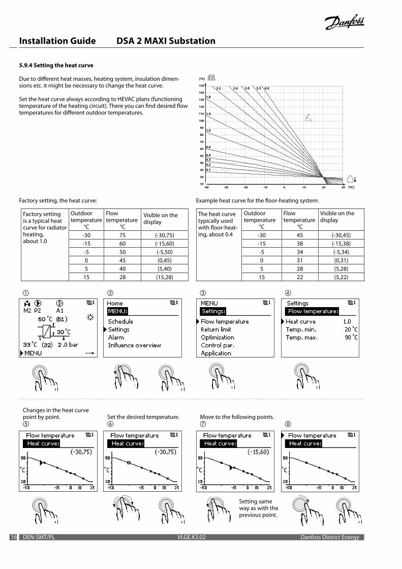
5.9.4 Setting the heat curve
Due to different heat masses, heating system, insulation dimen-sions etc. it might be necessary to change the heat curve.
Set the heat curve always according to HEVAC plans (functioning temperature of the heating circuit). There you can find desired flow temperatures for different outdoor temperatures.
10
20
30
40
50
60
70
80
90
100
110
120
130
140
150
-40 -30 -20 -10 0 10 20 30 [oC]
[oC]
1.0
1.4
0.6
0.2
1.8
2.2 3.0 3.52.6 4.0
0.1
0.30.4
Factory setting, the heat curve: Example heat curve for the floor-heating system:
Factory setting is a typical heat curve for radiator heating, about 1.0
Outdoor temperature
°C
Flow temperature
°C
Visible on the display
-30 75 (-30,75)-15 60 (-15,60)-5 50 (-5,50)0 45 (0,45)5 40 (5,40)
15 28 (15,28)
The heat curve typically used with floor-heat-ing, about 0.4
Outdoor temperature
°C
Flow temperature
°C
Visible on the display
-30 45 (-30,45)-15 38 (-15,38)-5 34 (-5,34)0 31 (0,31)5 28 (5,28)
15 22 (5,22)
Changes in the heat curve point by point.
Set the desired temperature.
Move to the following points.
Setting same way as with the previous point.

Installation Guide DSA 2 MAXI Substation
1717Danfoss District Energy VI.GE.K3.02 DEN-SMT/PL
Saving the new curve. Getting out of the menu.
5.9.5 Setting up limitations for flow temperature
The flow temperature maximum limitation prevents too hot water from going into the heating circuit, e.g. in the floor-heating system.
When taking floor-heating system into use for the first time, the max. limitation for flow temperature can be set e.g. at 27°C. The limitation temperature cuts off the heat curve when the tempera-ture reaches the limit.Later on after the concrete slab has dried the flow temperature limitation can be raised to 45°C which is typically used in the floor-heating system.
Typical max. limitation in the radiator heating circuit is 90°C.
Typical flow temperature limitations in different heating systems
Flow temperature
min °C max °C
Radiator heating 20 90When taking floor-heating system into use for the first time (drying up concrete slab)
20 27
Floor-heating 20 45
Setting the flow temperature max. limitation.
Typical flow temperature max. limitation: floor-heating 45°C.
Setting the flow temperature min. limitation.
Typical flow temperature max. limitation: radiator heating 90°C.
The heat curve display by fol-lowing the intructions in “5.9.4 Setting the heat curve”.
.

Installation Guide DSA 2 MAXI Substation
18 DEN-SMT/PL VI.GE.K3.02 Danfoss District Energy
Typical flow temperature max. limitation: When taking floor-heating system into use for the first time (drying up concrete slab) 27°C.
Example display of the heat curve limiting temperature: floor-heating heat curve, flow temp. max limitation 27°C.
Getting out of the menu.
The heat curve display by fol-lowing the intructions in “5.9.4 Setting the heat curve”.
Getting out of the menu.
Typical flow temperature min. limitation is 20°C.
5.9.6 Manual control
Manual control is typically used when installing or servicing. The controlled components, valve, pump etc. can be controlled for correct function.
Do not leave the controller in “Manual control” mode after finishing maintenance or service work. The normal mode is “Comfort mode” or when using schedules “Scheduled operation” .
The valve is open.

Installation Guide DSA 2 MAXI Substation
1919Danfoss District Energy VI.GE.K3.02 DEN-SMT/PL
The valve is closed.
Getting away.
Changing back to Comfort mode.
5.9.7 Commissioning with one circuit
When commissioning the substation it might be necessary to close a circuit, e.g. DHW circuit. The circuit in question can be closed by forcing the control valve to close down.The pump has to be stopped with an operating switch.
M1, P1 DHW circuit control valve and circulation pump
M2, P2 Heating circuit control valve and circulation pump
A1 Alarm relay
An example: DHW circuit control valve close down.
The valve is forced to close down.
STOP leaves the valve in closed position.
Getting out of the menu.

Installation Guide DSA 2 MAXI Substation
20 DEN-SMT/PL VI.GE.K3.02 Danfoss District Energy
5.9.8 Sensor displays
Temperature and pressure information can be read on the con-troller display.
All values can be found by going down the list.
Getting out of the menu.
5.9.9 Alarm
Alarm functions in the controller: pressure alarm, pump alarm and maximum temperature alarm (temperature limiting thermo-static function). As a sign of an alarm symbol appears on the display.
Alarm overview shows which alarm is in question.

Installation Guide DSA 2 MAXI Substation
2121Danfoss District Energy VI.GE.K3.02 DEN-SMT/PL
Pressure alarm.
Max and min limitations (Alarm high, Alarm low) have to adapted to the building. Low X and high X values have been set based on the pressure transmitter included. Do not change!
Pump alarm. The alarm disap-pears from the display when the pump is working again.
Alarm value:1=open contact (eg. Wilo)0= closing contact (e.g. Grund-fos)
Max temperature limitation (temperature limiting thermo-static function).
Max temperature limitation can be used e.g. in floor-heating system as a temperature limiting thermostatic function.
Getting out of the menu.
In a floor-heating system the maximum temperature limita-tion can be set at 50°C.

Installation Guide DSA 2 MAXI Substation
22 DEN-SMT/PL VI.GE.K3.02 Danfoss District Energy
5.9.10 Changing the favourite display for the user
After having done the installation settings, it is recommendable to change the favourite display to fit the user’s needs.
5.9.11 Setting the room temperature
The setting of the desired room temperature is important even if the room temperature sensor is not connected. It has an effect on the temperature in your property.
5.9.12 Setting domestic hot water temperature
Changing the circuit.

Installation Guide DSA 2 MAXI Substation
2323Danfoss District Energy VI.GE.K3.02 DEN-SMT/PL
Changing the desired tempera-ture. Getting out of the menu.
5.10 Basic parameters, factory settings
Heating circuit
Setting Factory set-ting
Own setting Comment
Room temperature and setback temp. 20 °C/ 16 °C
Heat curve 1.0 Note! In a floor-heating system the typical setting is 0.4.
Limit for heating cut-out 18 °C
Flow temperature min. 20 °C
Flow temperature max. 90 °C Note! In a floor-heating system change the max. temp. to 45 °C.
Proportional band Xp 85 K
Integration time constant Tn 25 s
Running time of the motorized con-trol valve
120 s
Neutral zone Nz 2 K
Pressure alarm limit max 2.3
Pressure alarm limit min 0.8
Pressure alarm timeout 30 s
Pump alarm, alarm value 1 1= open contact (e.g. Wilo)0= closing contact (e.g. Grundfos)
Pump alarm, timeout 20 s
Max flow temperature limitation alarm (temperature limiting thermostatic function)
90 °C Note! In a floor-heating system change to 50 °C.
Max flow temperature limitation alarm, timeout ΔTALARM
60 s
DHW circuit Setting Factory set-
tingOwn setting Comment
DHW temperature and setback temp. 58 °C/ 55 °C
Flow temperature min. 45 °C
Flow temperature max. 65 °C
Proportional band Xp 9 K
Integration time constant Tn 13 s
Running time of the motorized control valve
15 s
Neutral zone Nz 3 K

Installation Guide DSA 2 MAXI Substation
24 DEN-SMT/PL VI.GE.K3.02 Danfoss District Energy
Problems Heating
Room temperature is too lowi.e. flow temperature is too low.
Disruption in the district heating distribution.
Get in contact with the district heating distributor.
The filter is clogged.Get in contact with the district heating distributor or with local Danfoss Sales Company.
The heat curve is not correct. Check the heat curve settings.
Failure in the heating circuit controls. Get in contact with local Danfoss Sales Company.
The circulation pump has stopped. Turn the pump on, check e.g. heat relay.
Pressure in the heating circuit is too low. Add water through the filling valve. Write down the filling date.
Air in the heating circuit. Remove air from the radiators, add water if necessary.
Fouling in the heat exchanger. Get in contact with local Danfoss Sales Company.
The radiator thermostat is stuck or broken. Get in contact with the installer.
The control valve is stuck. Get in contact with local Danfoss Sales Company.
Room temperature is too highi.e. flow temperature is too high.
The heat curve is not correct. Check the heat curve settings.
The controller in the heating circuit is broken.Get in contact with local Danfoss Sales Company.
The control valve stays open/closed.
5.11 Start-up
Check following point before start-up:
Check points, before start-up
Pipes are connected according to the designs.Drainage valves are closed.The temperature for the domestic hot water is set to +58˚C.The outdoor temperature sensor is installed and connected.Controller settings.Connections are tightened.Function of the safety valves is checked.
Fill the substation with flow media and raise the pressure slowly to working pressure. When starting up the substation it should be air vented. The shut-off valve in the primary side on the return side is opened and the shut-off valve on the supply side is closed. Air comes out by open-ing the air vent valve.After that the operation of the substation must be observed. If the substation operates according to designed parameters, it can be taken into continuous use.
Check points, after start-up
Check temperaturesCheck pressures.Thermal expansion.Operation of the pumps.Flow directions.Operation of the controls.
All Danfoss heat exchangers and substations have been pres-sure tested according to PED 97/23/EC (module H).
Make sure to give operating instructions to the users of the substation.
6.0 Trouble shooting

Installation Guide DSA 2 MAXI Substation
2525Danfoss District Energy VI.GE.K3.02 DEN-SMT/PL
6.0 Trouble shooting
Problems Domestic hot water (DHW)
DHW smells bad or is coloured. DHW heat exchanger has an internal leakage.
Get in contact with local Danfoss Sales Company.
Temperature of DHW varies more than usual.
DHW control does not work or the control valve is broken.
DHW control valve is too big for the existing conditions.
Inadequate DHW circulation. Get in contact with the installer.
The filter is clogged. Get in contact with the district heating distributor.
The pressure difference is too big.Get in contact with local Danfoss Sales Company.
Trash in the control valve.
Other situations
The pump sounds strange.Air lock in the pump. Stop the pump for a moment to remove the
air lock.
The bearing in the pump is broken.Get in contact with the district heating distributor.
The control valve has a strong, whistling sound.
The control valve is broken.
Pressure difference is too big in the district heating network.
Get in contact with the district heating distributor.
Water leaks on the floor in the boiler room or the heat exchanger insulation is wet. The heat exchanger has an external leakage.
Get in contact with the district heating distributor and/or local Danfoss Sales Company.
The pressure or the temperature of district heating water differs significantly from the normal.
Disruption in the district heating distribution Get in contact with the district heating distributor.
The outdoor temperature is not visible on the display.
The outdoor temperature sensor has been connected to the substation with the power on.
Pull the substation contact plug out and reconnect it.
Heating control does not work.
The controller is let in ”Manual control” mode.
Set the controller to ”Comfort mode” or ”Scheduled operation mode”.
The controller, sensor or motorized control valve is broken. Get in contact with local Danfoss Sales
Company.The control valve stays open/closed.
Water in the heating circuit increases and excess water comes out through the safety valve for the expansion vessel.
The heat exchanger has an internal leakage.Get in contact with the district heating distributor and/or with local Danfoss Sales Company.
The filling valve in the heating circuit leaks into the heating circuit.
Get in contact with local Danfoss Sales Company.
Pressure in the heating circuit is too low. The heating circuit has too little water or the ciruit has a leakage.
Add water into the circuit through the filling valve. Write down the filling date. If this happens often, get in contact with local Danfoss Sales Company.
The return temperature in the heating circuit is high.
The difference between district heating and heating circuit return temperatures is big.
Get in contact with local Danfoss Sales Company.

Installation Guide DSA 2 MAXI Substation
26 DEN-SMT/PL VI.GE.K3.02 Danfoss District Energy
Declaration of conformityPressure equip
ment in accordance w
ith the sound engineering practice
(Directive 97/23/EC
, Article 3.3)
Pressure equipm
ent in hazard category I (D
irective 97/23/EC, A
rticle 9.)

Installation Guide DSA 2 MAXI Substation
2727Danfoss District Energy VI.GE.K3.02 DEN-SMT/PL
Declaration of conformity
Disposal instruction:This product should be dismantled and its components sorted, if possible, in various groups before recycling or disposal. Always follow the local disposal regulations.
Pressure equipm
ent in hazard category II - III (D
irective 97/23/EC, A
rticle 9.)

Installation Guide DSA 2 MAXI Substation
Produced by Danfoss A/S © 05/2012
Danfoss Poland Sp. z o.o. · Tuchom, ul. Tęczowa 46 · 80-209 ChwaszczynoTel.: +48 58 512 91 00 · Fax: +48 58 512 91 05 · [email protected] · www.danfoss.com