Embed Size (px)
Citation preview

Model FS19X™ & FS20X™ Fire and Flame Detectors Installation Guide and Operating Manual MAN0925_V1 (6178-004G)_08-12
____________________________________________________________________________________________________________________ Fire Sentry Corporation Document No. 6178-004 - Rev. G © Copyright 2011 All Rights Reserved
Installation Guide and Operating Manual
Fire Sentry Model FS19XTM and FS20XTM Series Fire Sentry FS19X & FS20X WideBand IRTM / UV Multi-Spectrum Infrared / Ultraviolet Electro-Optical Multi-Spectral Digital WideBand IR Sensor with Ultraviolet Phototube Radiant Energy Fire and Flame Detector

Model FS19X™ & FS20X™ Fire and Flame Detectors Installation Guide and Operating Manual MAN0925_V1 (6178-004G)_08-12
i | P a g e
Model FS19X™ & FS20X™ Fire and Flame Detectors Installation Guide and Operating Manual MAN0925_V1 (6178-004G)_08-12
i | P a g e
TABLE OF CONTENTSU UPAGE
TUSECTION 1: INTRODUCTION UT .............................................................................................................................. 1 TU1.1UT TUProduct Overview UT ....................................................................................................................................... 1 TU1.2UT TUDetector Technical Specifications UT ............................................................................................................... 1
TU1.2.1UT TUMechanical Specifications UT ............................................................................................................... 1 TU1.2.2 Electrical Specifications ................................................................................................................... 2 U1.2.3U UEnvironmental Specifications U........................................................................................................... 2 U1.2.4U UPerformance Specifications U ............................................................................................................. 2 U1.2.5U Hazardous Area Classifications U ....................................................................................................... 2
U1.3 Features & Benefits .................................................................................................................................... 3 U1.4 Applications ................................................................................................................................................ 4
USECTION 2: INSTALLATION U ................................................................................................................................ 5 U2.1 Mounting Instructions .................................................................................................................................. 5 U2.2 Opening the Detector .................................................................................................................................. 6 U2.3 Detector Connections ................................................................................................................................. 7 U2.4 Installation Practices ................................................................................................................................... 8 U2.5 Start-Up and Commissioning ...................................................................................................................... 9
USECTION 3: OPERATION .................................................................................................................................... 11U U3.1 Principle of Operation ................................................................................................................................ 11 U3.2 Configuring the Detector ............................................................................................................................ 11 U3.3 Normal Operation ...................................................................................................................................... 13 U3.4 Alarm Condition ......................................................................................................................................... 13 U3.5 Fault Conditions ......................................................................................................................................... 14 U3.6 LED Status Indicators ................................................................................................................................ 13 U3.7 Maintenance .............................................................................................................................................. 14
USECTION 4: APPENDIX ....................................................................................................................................... 15U U4.1 Warranty Information ................................................................................................................................. 15 U4.2 Product Variations ..................................................................................................................................... 16 U4.3 Digital Communication Options .................................................................................................................. 16 U4.4 Test Lamps ................................................................................................................................................ 17 U4.5 Field of View Restrictor .............................................................................................................................. 17 4.6 Additional Performance Specifications ....................................................................................................... 18
4.6.1 Flame Response Sensitivity ............................................................................................................ 18 4.6.2 High Temperature Response .......................................................................................................... 18 4.6.3 False Alarm Immunity ..................................................................................................................... 19
4.7 Drawings..................................................................................................................................................... 20 4.7.1 Outline and Dimensions .................................................................................................................. 20 4.7.2 Wiring and Terminal Connections .................................................................................................... 21 4.7.3 Detector Label Drawings .................................................................................................................. 23
UINDEX ................................................................................................................................................................... 25U
Model FS19X™ & FS20X™ Fire and Flame Detectors Installation Guide and Operating Manual MAN0925_V1 (6178-004G)_08-12
1 | P a g e
SECTION 1: INTRODUCTION 1.1 Product Overview
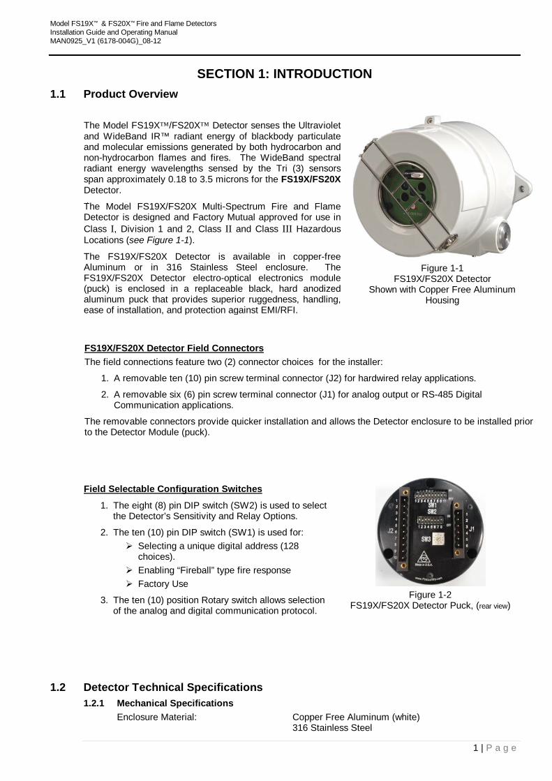
The Model FS19X™/FS20X™ Detector senses the Ultraviolet and WideBand IR™ radiant energy of blackbody particulate and molecular emissions generated by both hydrocarbon and non-hydrocarbon flames and fires. The WideBand spectral radiant energy wavelengths sensed by the Tri (3) sensors span approximately 0.18 to 3.5 microns for the FS19X/FS20X Detector.
The Model FS19X/FS20X Multi-Spectrum Fire and Flame Detector is designed and Factory Mutual approved for use in Class I, Division 1 and 2, Class II and Class III Hazardous Locations (see Figure 1-1).
The FS19X/FS20X Detector is available in copper-free Aluminum or in 316 Stainless Steel enclosure. The FS19X/FS20X Detector electro-optical electronics module (puck) is enclosed in a replaceable black, hard anodized aluminum puck that provides superior ruggedness, handling, ease of installation, and protection against EMI/RFI.
Figure 1-1
FS19X/FS20X Detector Shown with Copper Free Aluminum
Housing
FS19X/FS20X Detector Field Connectors The field connections feature two (2) connector choices for the installer:
1. A removable ten (10) pin screw terminal connector (J2) for hardwired relay applications.
2. A removable six (6) pin screw terminal connector (J1) for analog output or RS-485 Digital Communication applications.
The removable connectors provide quicker installation and allows the Detector enclosure to be installed prior to the Detector Module (puck).
UField Selectable Configuration Switches
1. The eight (8) pin DIP switch (SW2) is used to select the Detector’s Sensitivity and Relay Options.
2. The ten (10) pin DIP switch (SW1) is used for: Selecting a unique digital address (128
choices). Enabling “Fireball” type fire response Factory Use
3. The ten (10) position Rotary switch allows selection of the analog and digital communication protocol.
Figure 1-2
FS19X/FS20X Detector Puck, (rear view)
1.2 Detector Technical Specifications 1.2.1 Mechanical Specifications
Enclosure Material: Copper Free Aluminum (white) 316 Stainless Steel
Model FS19X™ & FS20X™ Fire and Flame Detectors Installation Guide and Operating Manual MAN0925_V1 (6178-004G)_08-12
2 | P a g e
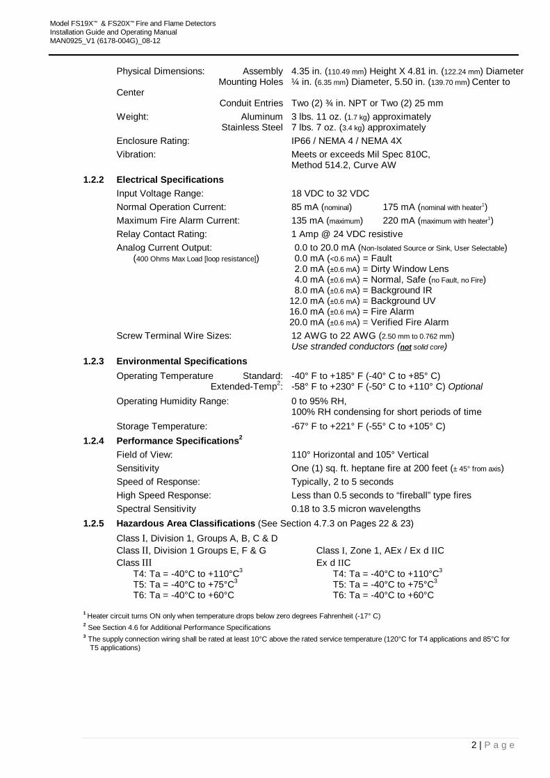
Physical Dimensions: Assembly 4.35 in. (110.49 mm) Height X 4.81 in. (122.24 mm) Diameter Mounting Holes ¼ in. (6.35 mm) Diameter, 5.50 in. (139.70 mm) Center to Center Conduit Entries Two (2) ¾ in. NPT or Two (2) 25 mm Weight: Aluminum 3 lbs. 11 oz. (1.7 kg) approximately Stainless Steel 7 lbs. 7 oz. (3.4 kg) approximately Enclosure Rating: IP66 / NEMA 4 / NEMA 4X Vibration: Meets or exceeds Mil Spec 810C, Method 514.2, Curve AW
1.2.2 Electrical Specifications Input Voltage Range: 18 VDC to 32 VDC Normal Operation Current: 85 mA (nominal) 175 mA (nominal with heater P
1P)
Maximum Fire Alarm Current: 135 mA (maximum) 220 mA (maximum with heater P
1P)
Relay Contact Rating: 1 Amp @ 24 VDC resistive Analog Current Output: 0.0 to 20.0 mA (Non-Isolated Source or Sink, User Selectable) (400 Ohms Max Load [loop resistance]) 0.0 mA (<0.6 mA) = Fault 2.0 mA (±0.6 mA) = Dirty Window Lens 4.0 mA (±0.6 mA) = Normal, Safe (no Fault, no Fire) 8.0 mA (±0.6 mA) = Background IR 12.0 mA (±0.6 mA) = Background UV 16.0 mA (±0.6 mA) = Fire Alarm 20.0 mA (±0.6 mA) = Verified Fire Alarm Screw Terminal Wire Sizes: 12 AWG to 22 AWG (2.50 mm to 0.762 mm) Use stranded conductors (Unot U solid core)
1.2.3 Environmental Specifications Operating Temperature Standard: -40° F to +185° F (-40° C to +85° C) Extended-TempP
2P: -58° F to +230° F (-50° C to +110° C) Optional
Operating Humidity Range: 0 to 95% RH, 100% RH condensing for short periods of time Storage Temperature: -67° F to +221° F (-55° C to +105° C)
1.2.4 Performance SpecificationsP
2P
Field of View: 110° Horizontal and 105° Vertical Sensitivity One (1) sq. ft. heptane fire at 200 feet (± 45° from axis) Speed of Response: Typically, 2 to 5 seconds High Speed Response: Less than 0.5 seconds to “fireball” type fires Spectral Sensitivity 0.18 to 3.5 micron wavelengths
1.2.5 Hazardous Area Classifications (See Section 4.7.3 on Pages 22 & 23) Class I, Division 1, Groups A, B, C & D Class II, Division 1 Groups E, F & G Class I, Zone 1, AEx / Ex d IIC Class III Ex d IIC T4: Ta = -40°C to +110°C3 T4: Ta = -40°C to +110°C3 T5: Ta = -40°C to +75°C3 T5: Ta = -40°C to +75°C3 T6: Ta = -40°C to +60°C T6: Ta = -40°C to +60°C
1 PHeater circuit turns ON only when temperature drops below zero degrees Fahrenheit (-17° C) P
2 See Section 4.6 for Additional Performance Specifications 3 The supply connection wiring shall be rated at least 10°C above the rated service temperature (120°C for T4 applications and 85°C for
T5 applications)
Model FS19X™ & FS20X™ Fire and Flame Detectors Installation Guide and Operating Manual MAN0925_V1 (6178-004G)_08-12
3 | P a g e
1.3 Features and Benefits • Selectable Sensitivity (four settings)
User can set an F20SX Detector to four (4) different detection distances (see Section 3.2).
• Selectable Relay Options User can configurable for a variety of dry contact relay interface options (see Section 3.2).
• Selectable 4 – 20 mA Output User can set for Source or Sink output (see Section 3.2).
• Selectable Communications User can configure for analog or digital communication outputs such as ModBus (see Section 3.2).
• Selectable Digital Communication Address Users can select unique 7-bit code (128 addresses) (see Section 3.2).
• Lower Power Consumption Requires smaller external power supplies and fewer system backup batteries.
• Multiple Microprocessors Reduces the number of discrete Detector components, provides larger programming and memory capacity, and provides redundant self-checking.
• Wider Range of Applications Primary applications include long range, fast response to fires such as acetylene, silane, hydrogen, etc.
• Wider Operating Temperatures -40°F to +185°F (-40°C to +85°C) Standard and -76°F to +230°F (-60°C to +110°C) Optional.
• Built-In Automatic “Through-the-Lens” Self-Test Monitors window lens obscuration and checks the operation of the Detector’s Sensor Array and Electro-Optical Electronics Module with Built-In IR (FS19X & FS20X) and UV (FS20X) Self-Tests.
• Anodized Removable Detector Aluminum Module (Puck) Rugged, superior protection against EMI/RFI and handling plus easier field installation and replacement.
• Three Separate Bright LED’s (Red, Yellow, Blue) Field status indicators with individual LED’s for Alarm, Fault and Normal conditions. Provides superior Detector status viewing in bright outdoor environments (see Section 3.6).
• FSC Windows® based PC Interface User can perform remote FS20X Detector diagnostics, real-time status, Real-Time Graphing (RTG), SnapShot data recording, and downloading FirePic’s with Fire Sentry’s exclusive FSIM-2 USB Interface Unit and easy to use Windows® based PC Software.
• Designed to Detect both Hydrocarbon and Non-Hydrocarbon Fires with one FSX Detector All fire and flame threats are sensed, not just hydrocarbon fires as with other Triple IR Flame Detectors.
• FM 3260 Approved Third party tested and certified for industrial and commercial applications.
• Designed, Manufactured, and Tested by Fire Sentry Corporation Over 25 years of proven fire / flame detection product excellence worldwide.
Model FS19X™ & FS20X™ Fire and Flame Detectors Installation Guide and Operating Manual MAN0925_V1 (6178-004G)_08-12
4 | P a g e
1.4 Applications The applications for the FS19X/FS20X Fire and Flame Detectors are vast. Here is a partial list:
Refineries
Offshore Drilling and Production Platforms
Petrochemical Plants
Petroleum Product Pipelines and Pumping Stations
Gas Compressor Buildings
Gas Collection Facilities
Gas Processing Plants
Gas Turbine Enclosures
Gasoline Loading Terminals
LNG Storage/Distribution
LPG Storage/Distribution
Cogeneration Plants
Crude and Product Tank Farms
Aerosol Filling Facilities
Commercial and Military Aircraft Hangars
Engine Test Cells
Marine Engine Rooms
Marine Terminals
Paint and Solvent Storage
Power Plants
Product Storage Terminals
Rail and Truck Loading and Unloading Terminals
Silane Gas Cabinets
Silane Gas Manufacturing
Hydrogen Plants
Hydrogen Storage
General Warehouses
Model FS19X™ & FS20X™ Fire and Flame Detectors Installation Guide and Operating Manual MAN0925_V1 (6178-004G)_08-12
5 | P a g e
SECTION 2: INSTALLATION 2.1 Mounting Instructions
Consider the following guidelines when selecting Detector location:
1. As with all flame and fire Detectors, avoid areas that contain radiant energy sources (such as radiant heaters, high intensity lamps, flare-stacks, etc.) in close proximity to the Detector’s field of view.
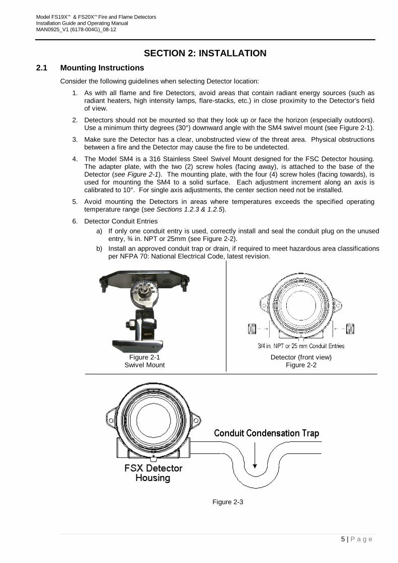
2. Detectors should not be mounted so that they look up or face the horizon (especially outdoors). Use a minimum thirty degrees (30°) downward angle with the SM4 swivel mount (see Figure 2-1).
3. Make sure the Detector has a clear, unobstructed view of the threat area. Physical obstructions between a fire and the Detector may cause the fire to be undetected.
4. The Model SM4 is a 316 Stainless Steel Swivel Mount designed for the FSC Detector housing. The adapter plate, with the two (2) screw holes (facing away), is attached to the base of the Detector (see Figure 2-1). The mounting plate, with the four (4) screw holes (facing towards), is used for mounting the SM4 to a solid surface. Each adjustment increment along an axis is calibrated to 10°. For single axis adjustments, the center section need not be installed.
5. Avoid mounting the Detectors in areas where temperatures exceeds the specified operating temperature range (see Sections 1.2.3 & 1.2.5).
6. Detector Conduit Entries a) If only one conduit entry is used, correctly install and seal the conduit plug on the unused
entry, ¾ in. NPT or 25mm (see Figure 2-2). b) Install an approved conduit trap or drain, if required to meet hazardous area classifications
per NFPA 70: National Electrical Code, latest revision.
Figure 2-1 Detector (front view) Swivel Mount Figure 2-2
Figure 2-3
Model FS19X™ & FS20X™ Fire and Flame Detectors Installation Guide and Operating Manual MAN0925_V1 (6178-004G)_08-12
6 | P a g e
Mounting Instructions (continued) Note the following Precautions:
1. UDo not touch U the sensors’ windows on the front of the Detector electro-optical electronics module (puck). If touched accidentally, they should be cleaned following the instructions listed below (see Figure 2-4).
2. When cleaning the Detector’s sensor windows on the puck, it is best to use Alcohol or IPA sparingly and a cotton swab.
3. There are no serviceable parts inside the Detector puck. If the puck is opened up or tampered with, all warranties are voided.
Detector Module “puck”
Figure 2-4
CAUTION: Follow static protection procedures while handling the connectors and the wiring of the Module puck to the Detector. Use a wrist strap connected to earth ground.
2.2 Opening the Detector It is necessary to remove the Detector Module “puck” from the enclosure to access the field connections.
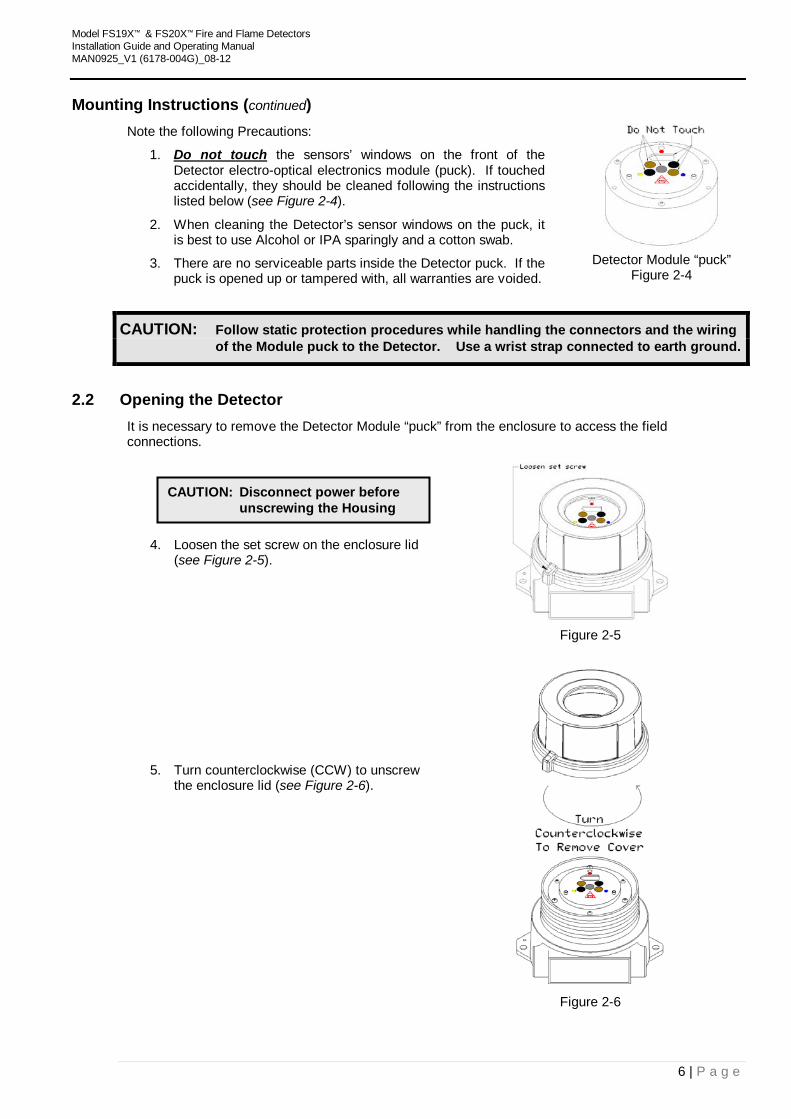
4. Loosen the set screw on the enclosure lid (see Figure 2-5).
Figure 2-5
5. Turn counterclockwise (CCW) to unscrew the enclosure lid (see Figure 2-6).
Figure 2-6
CAUTION: Disconnect power before unscrewing the Housing
Model FS19X™ & FS20X™ Fire and Flame Detectors Installation Guide and Operating Manual MAN0925_V1 (6178-004G)_08-12
7 | P a g e
Opening the Detector (continued)
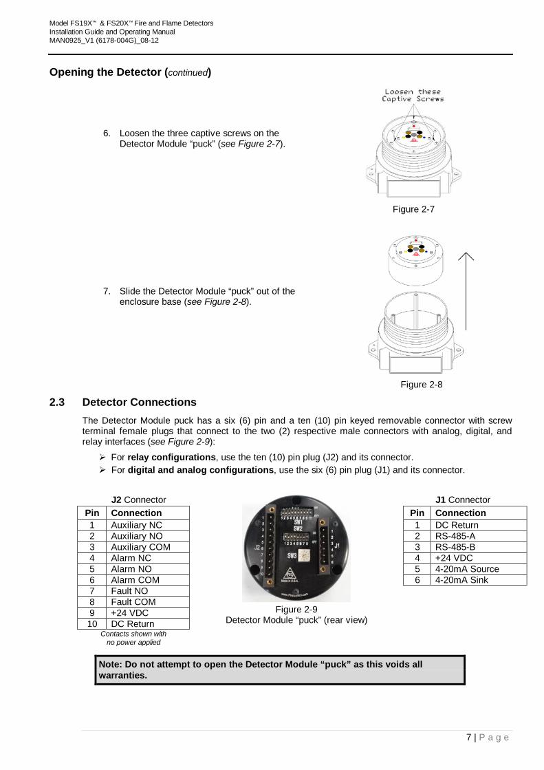
6. Loosen the three captive screws on the Detector Module “puck” (see Figure 2-7).
Figure 2-7
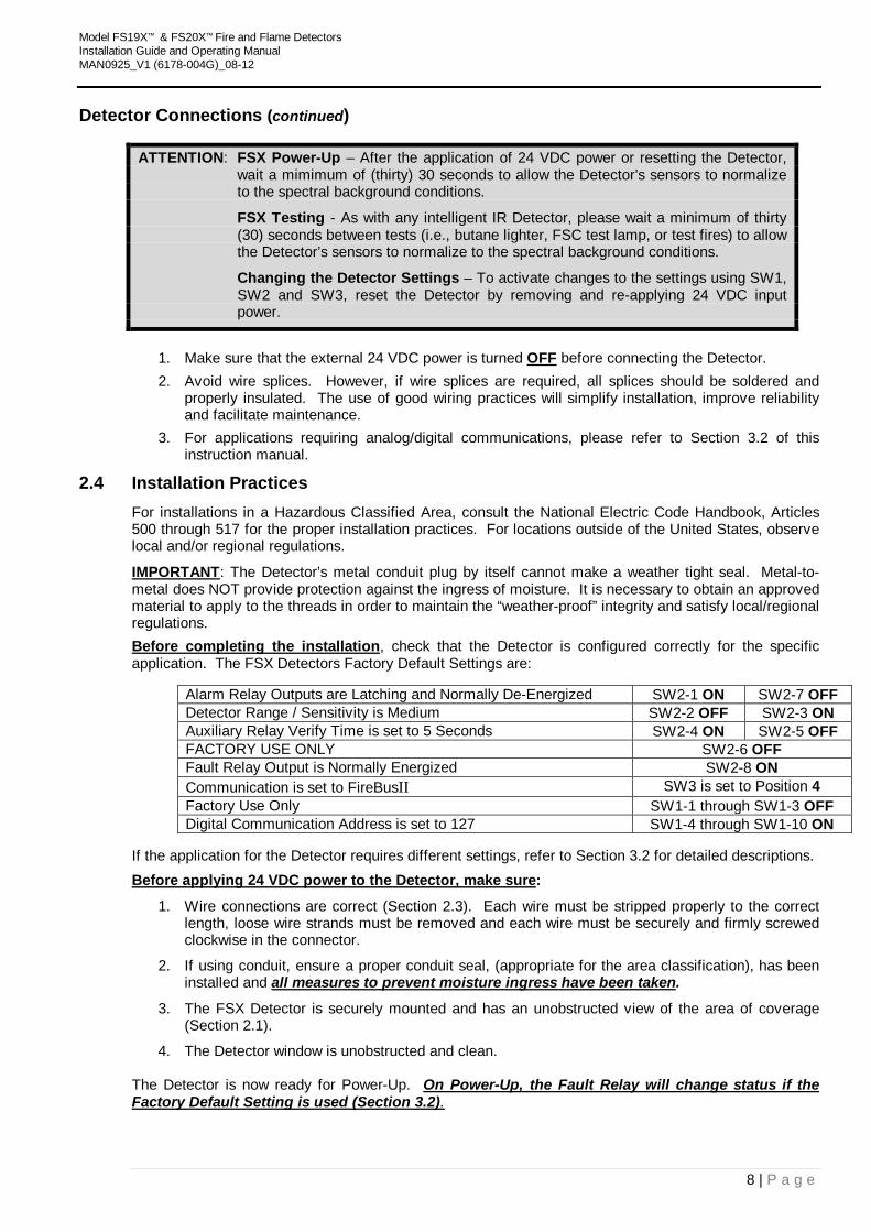
7. Slide the Detector Module “puck” out of the enclosure base (see Figure 2-8).
Figure 2-8
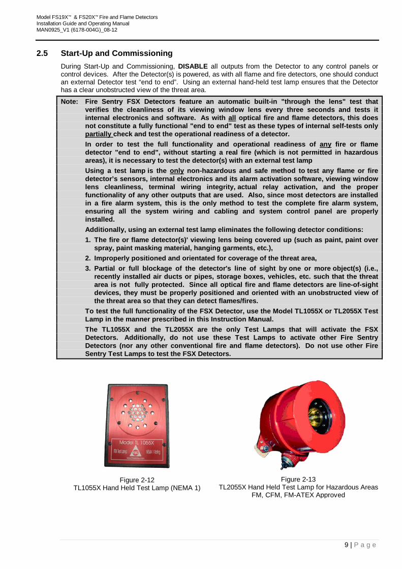
2.3 Detector Connections The Detector Module puck has a six (6) pin and a ten (10) pin keyed removable connector with screw terminal female plugs that connect to the two (2) respective male connectors with analog, digital, and relay interfaces (see Figure 2-9):
For relay configurations, use the ten (10) pin plug (J2) and its connector. For digital and analog configurations, use the six (6) pin plug (J1) and its connector.
J2 Connector
Figure 2-9
Detector Module “puck” (rear view)
J1 Connector Pin Connection Pin Connection 1 Auxiliary NC 1 DC Return 2 Auxiliary NO 2 RS-485-A 3 Auxiliary COM 3 RS-485-B 4 Alarm NC 4 +24 VDC 5 Alarm NO 5 4-20mA Source 6 Alarm COM 6 4-20mA Sink 7 Fault NO 8 Fault COM 9 +24 VDC 10 DC Return
Contacts shown with no power applied
Note: Do not attempt to open the Detector Module “puck” as this voids all warranties.
Model FS19X™ & FS20X™ Fire and Flame Detectors Installation Guide and Operating Manual MAN0925_V1 (6178-004G)_08-12
8 | P a g e
Detector Connections (continued)
ATTENTION: FSX Power-Up – After the application of 24 VDC power or resetting the Detector, wait a mimimum of (thirty) 30 seconds to allow the Detector’s sensors to normalize to the spectral background conditions.
FSX Testing - As with any intelligent IR Detector, please wait a minimum of thirty (30) seconds between tests (i.e., butane lighter, FSC test lamp, or test fires) to allow the Detector’s sensors to normalize to the spectral background conditions.
Changing the Detector Settings – To activate changes to the settings using SW1, SW2 and SW3, reset the Detector by removing and re-applying 24 VDC input power.
1. Make sure that the external 24 VDC power is turned UOFF U before connecting the Detector. 2. Avoid wire splices. However, if wire splices are required, all splices should be soldered and
properly insulated. The use of good wiring practices will simplify installation, improve reliability and facilitate maintenance.
3. For applications requiring analog/digital communications, please refer to Section 3.2 of this instruction manual.
2.4 Installation Practices For installations in a Hazardous Classified Area, consult the National Electric Code Handbook, Articles 500 through 517 for the proper installation practices. For locations outside of the United States, observe local and/or regional regulations.
IMPORTANT U: The Detector’s metal conduit plug by itself cannot make a weather tight seal. Metal-to-metal does NOT provide protection against the ingress of moisture. It is necessary to obtain an approved material to apply to the threads in order to maintain the “weather-proof” integrity and satisfy local/regional regulations. UBefore completing the installation U, check that the Detector is configured correctly for the specific application. The FSX Detectors Factory Default Settings are:
Alarm Relay Outputs are Latching and Normally De-Energized SW2-1 ON SW2-7 OFF Detector Range / Sensitivity is Medium SW2-2 OFF SW2-3 ON Auxiliary Relay Verify Time is set to 5 Seconds SW2-4 ON SW2-5 OFF FACTORY USE ONLY SW2-6 OFF Fault Relay Output is Normally Energized SW2-8 ON Communication is set to FireBusII SW3 is set to Position 4 Factory Use Only SW1-1 through SW1-3 OFF Digital Communication Address is set to 127 SW1-4 through SW1-10 ON
If the application for the Detector requires different settings, refer to Section 3.2 for detailed descriptions. U Before applying 24 VDC power to the Detector, make sureU:
1. Wire connections are correct (Section 2.3). Each wire must be stripped properly to the correct length, loose wire strands must be removed and each wire must be securely and firmly screwed clockwise in the connector.
2. If using conduit, ensure a proper conduit seal, (appropriate for the area classification), has been installed and Uall measures to prevent moisture ingress have been takenU.
3. The FSX Detector is securely mounted and has an unobstructed view of the area of coverage (Section 2.1).
4. The Detector window is unobstructed and clean. The Detector is now ready for Power-Up. UOn Power-Up, the Fault Relay will change status if the Factory Default Setting is used (Section 3.2).
Model FS19X™ & FS20X™ Fire and Flame Detectors Installation Guide and Operating Manual MAN0925_V1 (6178-004G)_08-12
9 | P a g e
2.5 Start-Up and Commissioning During Start-Up and Commissioning, DISABLE all outputs from the Detector to any control panels or control devices. After the Detector(s) is powered, as with all flame and fire detectors, one should conduct an external Detector test “end to end”. Using an external hand-held test lamp ensures that the Detector has a clear unobstructed view of the threat area.
Note: Fire Sentry FSX Detectors feature an automatic built-in "through the lens" test that verifies the cleanliness of its viewing window lens every three seconds and tests it internal electronics and software. As with Uall U optical fire and flame detectors, this does not constitute a fully functional "end to end" test as these types of internal self-tests only Upartially Ucheck and test the operational readiness of a detector.
In order to test the full functionality and operational readiness of UanyU fire or flame detector "end to end", without starting a real fire (which is not permitted in hazardous areas), it is necessary to test the detector(s) with an external test lamp
Using a test lamp is the UonlyU non-hazardous and safe method to test any flame or fire detector’s sensors, internal electronics and its alarm activation software, viewing window lens cleanliness, terminal wiring integrity, actual relay activation, and the proper functionality of any other outputs that are used. Also, since most detectors are installed in a fire alarm system, this is the only method to test the complete fire alarm system, ensuring all the system wiring and cabling and system control panel are properly installed.
Additionally, using an external test lamp eliminates the following detector conditions: 1. The fire or flame detector(s)' viewing lens being covered up (such as paint, paint over
spray, paint masking material, hanging garments, etc.), 2. Improperly positioned and orientated for coverage of the threat area, 3. Partial or full blockage of the detector's line of sight by one or more object(s) (i.e.,
recently installed air ducts or pipes, storage boxes, vehicles, etc. such that the threat area is not fully protected. Since all optical fire and flame detectors are line-of-sight devices, they must be properly positioned and oriented with an unobstructed view of the threat area so that they can detect flames/fires.
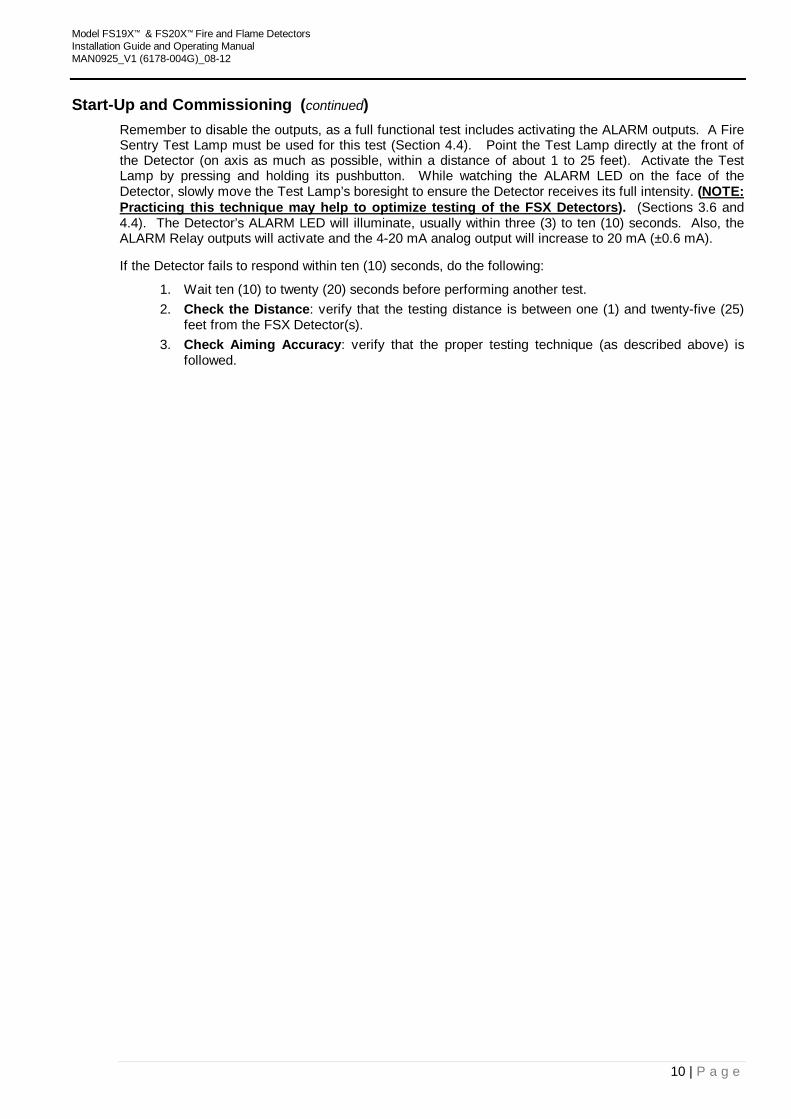
To test the full functionality of the FSX Detector, use the Model TL1055X or TL2055X Test Lamp in the manner prescribed in this Instruction Manual.
The TL1055X and the TL2055X are the only Test Lamps that will activate the FSX Detectors. Additionally, do not use these Test Lamps to activate other Fire Sentry Detectors (nor any other conventional fire and flame detectors). Do not use other Fire Sentry Test Lamps to test the FSX Detectors.
Figure 2-12
TL1055X Hand Held Test Lamp (NEMA 1) Figure 2-13
TL2055X Hand Held Test Lamp for Hazardous Areas FM, CFM, FM-ATEX Approved
Model FS19X™ & FS20X™ Fire and Flame Detectors Installation Guide and Operating Manual MAN0925_V1 (6178-004G)_08-12
10 | P a g e
Start-Up and Commissioning (continued) Remember to disable the outputs, as a full functional test includes activating the ALARM outputs. A Fire Sentry Test Lamp must be used for this test (Section 4.4). Point the Test Lamp directly at the front of the Detector (on axis as much as possible, within a distance of about 1 to 25 feet). Activate the Test Lamp by pressing and holding its pushbutton. While watching the ALARM LED on the face of the Detector, slowly move the Test Lamp’s boresight to ensure the Detector receives its full intensity. (UNOTE: Practicing this technique may help to optimize testing of the FSX DetectorsU). (Sections 3.6 and 4.4). The Detector’s ALARM LED will illuminate, usually within three (3) to ten (10) seconds. Also, the ALARM Relay outputs will activate and the 4-20 mA analog output will increase to 20 mA (±0.6 mA).
If the Detector fails to respond within ten (10) seconds, do the following:
1. Wait ten (10) to twenty (20) seconds before performing another test. 2. Check the Distance: verify that the testing distance is between one (1) and twenty-five (25)
feet from the FSX Detector(s). 3. Check Aiming Accuracy: verify that the proper testing technique (as described above) is
followed.
Model FS19X™ & FS20X™ Fire and Flame Detectors Installation Guide and Operating Manual MAN0925_V1 (6178-004G)_08-12
11 | P a g e
SECTION 3: OPERATION 3.1 Principle of Operation
Fire Sentry Corporation’s Multi-Spectrum, Multi-Spectral and MultiBand™ Infrared and Ultraviolet Fire and Flame Detectors are sophisticated, state of the art, electro-optical digital radiant energy Detectors that sense the wideband radiant energy emitted by fire’s combustion processes that include flames’ molecular emissions and hot particulate blackbody emissions. Radiant Energy Fire Detectors respond much faster to flames and fires at a longer distance than other types of conventional photoelectric and ionization smoke and heat detectors because a fire’s emitted radiant energy travels at the speed of light. High speed of response is critical for detecting flaming fires in time to successfully activate suppression or activate other fire responses such as closing fire doors. Seconds can make the difference between suppressing a small fire with little or no damage or having a disastrous fire that overwhelms a suppression system thereby failing to stop the fire.
Infrared (IR) consists of spectral wavelengths longer than the color red and Ultraviolet (UV) consists of wavelengths shorter than the color violet. For the FS19X/FS20X Detector, the UV and IR range for fire detection, which a large portion of the spectrum is invisible to the human eye, is from approximately 180 to 3000 nanometers (0.18 to 3.0 microns). Fire Sentry’s Detectors sense and measure the radiant energy generated by a fire at the speed of light.
Fire Sentry’s FSX Fire Detectors also use an additional spectral region, the Visible Band, that spans from about 400 to 700 nanometers (0.4 to 0.7 microns.) The Visible Band is used to further discriminate against non-fire false alarm sources. The Model FS19X/FS20X Detector senses radiant energy coming from hydrocarbon and non-hydrocarbon fires. Built-in microprocessors use sophisticated Digital Signal Processing (DSP) to accurately distinguish radiant energy from a real fire and a false alarm source(s). Fire Sentry has developed and refined these complex proprietary and patented WideBand IR and UV algorithms for over a quarter of a century since 1981. These patented algorithms perform real-time DSP, and precisely analyze the signals in high-resolution frequency and time domains. This decision making process involves thousands of real-time calculations every second. Fire Sentry FSX Detectors use solid-state high speed quantum sensors (not heat sensors such as pyroelectric or thermopile) that all respond to the fire’s radiant energy emissions. The quantum sensors convert the rate of photonic energy directly into analog electrical signals. These analog signals are converted to high resolution digital values for real-time microprocessor analysis.
The Detector microprocessors incorporate random access memory (RAM), read-only memory (ROM), and non-volatile flash memory. When the microprocessors determine that a real fire has been detected, the pre-alarm digital sensor data (FirePic™) and the event information are recorded in flash memory. Depending on the configuration, other actions may include activating one or more status LEDs, relays, a current loop and sending digital data such as the RS-485 FireBusII™, and ModBus. If the microprocessors determine, based on internal testing and “through-the-lens” testing, that the Detector is not operating correctly, it records the Fault data in flash memory and activates the Fault outputs and the yellow status LED. The digital data in the Detector can be easily accessed with a PC for later analysis and record keeping using Fire Sentry’s Windows® based PC software and FSIM-1A USB Interface Unit.
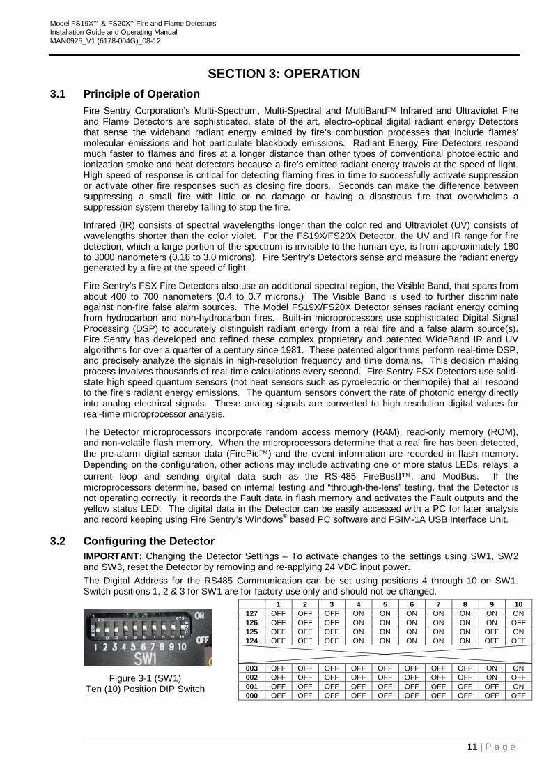
3.2 Configuring the Detector IMPORTANT: Changing the Detector Settings – To activate changes to the settings using SW1, SW2 and SW3, reset the Detector by removing and re-applying 24 VDC input power. The Digital Address for the RS485 Communication can be set using positions 4 through 10 on SW1. Switch positions 1, 2 & 3 for SW1 are for factory use only and should not be changed.
1 2 3 4 5 6 7 8 9 10
127 OFF OFF OFF ON ON ON ON ON ON ON 126 OFF OFF OFF ON ON ON ON ON ON OFF 125 OFF OFF OFF ON ON ON ON ON OFF ON 124 OFF OFF OFF ON ON ON ON ON OFF OFF 003 OFF OFF OFF OFF OFF OFF OFF OFF ON ON
Figure 3-1 (SW1) Ten (10) Position DIP Switch
002 OFF OFF OFF OFF OFF OFF OFF OFF ON OFF 001 OFF OFF OFF OFF OFF OFF OFF OFF OFF ON 000 OFF OFF OFF OFF OFF OFF OFF OFF OFF OFF
Model FS19X™ & FS20X™ Fire and Flame Detectors Installation Guide and Operating Manual MAN0925_V1 (6178-004G)_08-12
12 | P a g e
Configuring the Detector (continued)
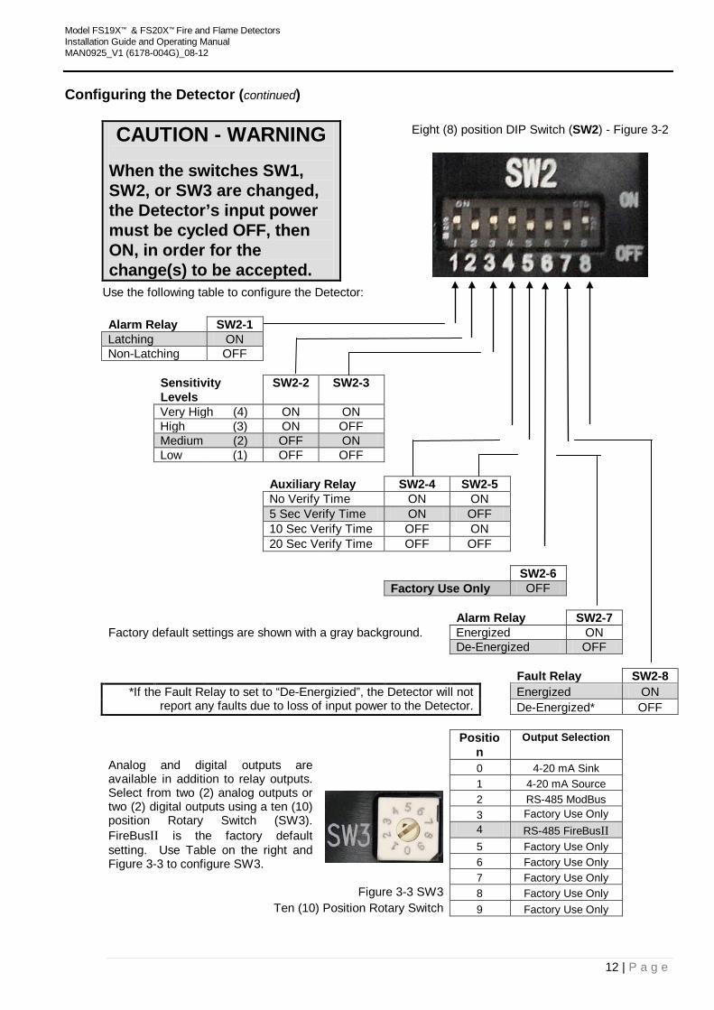
CAUTION - WARNING When the switches SW1, SW2, or SW3 are changed, the Detector’s input power must be cycled OFF, then ON, in order for the change(s) to be accepted.
Eight (8) position DIP Switch (SW2) - Figure 3-2
Use the following table to configure the Detector: Alarm Relay SW2-1 Latching ON Non-Latching OFF Sensitivity
Levels SW2-2 SW2-3
Very High (4) ON ON High (3) ON OFF Medium (2) OFF ON Low (1) OFF OFF Auxiliary Relay SW2-4 SW2-5 No Verify Time ON ON 5 Sec Verify Time ON OFF 10 Sec Verify Time OFF ON 20 Sec Verify Time OFF OFF SW2-6 Factory Use Only OFF Alarm Relay SW2-7 Factory default settings are shown with a gray background. Energized ON De-Energized OFF Fault Relay SW2-8
*If the Fault Relay to set to “De-Energizied”, the Detector will not report any faults due to loss of input power to the Detector.
Energized ON De-Energized* OFF
Analog and digital outputs are available in addition to relay outputs. Select from two (2) analog outputs or two (2) digital outputs using a ten (10) position Rotary Switch (SW3). FireBusII is the factory default setting. Use Table on the right and Figure 3-3 to configure SW3.
Position
Output Selection
0 4-20 mA Sink 1 4-20 mA Source
2 RS-485 ModBus 3 Factory Use Only 4 RS-485 FireBusII 5 Factory Use Only 6 Factory Use Only
7 Factory Use Only Figure 3-3 SW3 8 Factory Use Only
Ten (10) Position Rotary Switch 9 Factory Use Only
Model FS19X™ & FS20X™ Fire and Flame Detectors Installation Guide and Operating Manual MAN0925_V1 (6178-004G)_08-12
13 | P a g e
3.3 LED Status Indicators The Model FS19X/FS20X Detector uses three (3) separate, bright LED’s to indicate the Detector’s status.
The Blue LED blinks (flashes) once every ten (10) seconds to indicate a Normal, safe operational condition (i.e. no Faults and no Alarms). The Blue LED is OFF when no external 24 VDC input power is applied to the Detector.
The Red LED turns ON when a fire is Alarmed.
The Yellow LED blinks (flashes) when the window lens is dirty. For all other Fault conditions, the Yellow LED will turn ON.
3.4 Normal Operation In Normal operation, the bright Blue LED blinks (flashes) every 10 seconds. See Figure 3-4 for the location of the Blue LED. Normal Operation is defined as the Detector with 24 VDC applied and no Alarm or Fault conditions are present. If one of the 4-20 mA options are selected (Table 3-1), the current, sink or source, will be 4.0 mA (±0.06 mA).
Figure 3-4
Blue LED Location
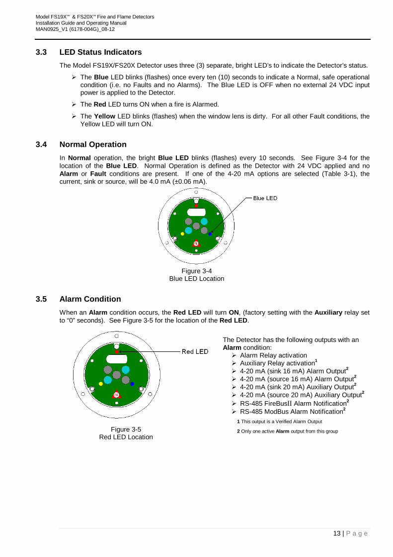
3.5 Alarm Condition When an Alarm condition occurs, the Red LED will turn ON, (factory setting with the Auxiliary relay set to “0” seconds). See Figure 3-5 for the location of the Red LED.
The Detector has the following outputs with an Alarm condition: Alarm Relay activation Auxiliary Relay activation1 4-20 mA (sink 16 mA) Alarm Output2 4-20 mA (source 16 mA) Alarm Output2 4-20 mA (sink 20 mA) Auxiliary Output2 4-20 mA (source 20 mA) Auxiliary Output2 RS-485 FireBusII Alarm Notification2 RS-485 ModBus Alarm Notification2
1 This output is a Verified Alarm Output
2 Only one active Alarm output from this group Figure 3-5
Red LED Location
Model FS19X™ & FS20X™ Fire and Flame Detectors Installation Guide and Operating Manual MAN0925_V1 (6178-004G)_08-12
14 | P a g e
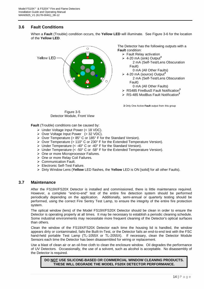
3.6 Fault Conditions When a Fault (Trouble) condition occurs, the Yellow LED will illuminate. See Figure 3-6 for the location of the Yellow LED.
The Detector has the following outputs with a Fault condition: Fault Relay activation 4-20 mA (sink) Output3 2 mA (Self-Test/Lens Obscuration
Fault) 0 mA (All Other Faults) 4-20 mA (source) Output3 2 mA (Self-Test/Lens Obscuration
Fault) 0 mA (All Other Faults) RS485 FireBusII Fault Notification3 RS-485 ModBus Fault Notification3
3 Only One Active Fault output from this group
Figure 3-5 Detector Module, Front View
Fault (Trouble) conditions can be caused by:
Under Voltage Input Power (< 18 VDC). Over Voltage Input Power (> 32 VDC). Over Temperature (> 85° C or 185° F for the Standard Version). Over Temperature (> 110° C or 230° F for the Extended Temperature Version). Under Temperature (< -40° C or -40° F for the Standard Version). Under Temperature (< -50° C or -58° F for the Extended Temperature Version). One or more Microprocessor Failures. One or more Relay Coil Failures. Communication Fault. Electronic Self-Test Failure. Dirty Window Lens (Yellow LED flashes, the Yellow LED is ON [solid] for all other Faults).
3.7 Maintenance After the FS19X/FS20X Detector is installed and commissioned, there is little maintenance required. However, a complete “end-to-end” test of the entire fire detection system should be performed periodically depending on the application. Additionally, semi-annual or quarterly testing should be performed, using the correct Fire Sentry Test Lamp, to ensure the integrity of the entire fire protection system. The optical window (lens) of the Model FS19X/FS20X Detector should be clean in order to ensure the Detector is operating properly at all times. It may be necessary to establish a periodic cleaning schedule. Some industrial environments may necessitate more frequent cleaning of the Detector’s optical surfaces than others. Clean the window of the FS19X/FS20X Detector each time the housing lid is handled, the window appears dirty or contaminated, fails the Built-In-Test, or the Detector fails an end-to-end test with the FSC hand-held portable Test Lamp (TL-1055X or TL-2055X). If necessary, clean the Detector Module Sensors each time the Detector has been disassembled for wiring or replacement. Use a blast of clean air or an oil-free cloth to clean the enclosure window. Oil degrades the performance of UV Detectors. Occassionally, the use of a solvent, such as alcohol is acceptable. No disassembly of the Detector is required.
DO NOT USE SILICONE-BASED OR COMMERCIAL WINDOW CLEANING PRODUCTS. THESE WILL DEGRADE THE MODEL FS20X DETECTOR PERFORMANCE.
Model FS19X™ & FS20X™ Fire and Flame Detectors Installation Guide and Operating Manual MAN0925_V1 (6178-004G)_08-12
15 | P a g e
SECTION 4: APPENDIX 4.1 Warranty Information
Fire Sentry Corporation warrants its Products against defects in material and workmanship under normal use and service for a period of Uthree (3) yearsU from the date of shipment as described herein. Fire Sentry Corporation, at its option, will repair or replace, at no charge, such products found to be defective during the warranty period provided that they are returned in accordance with the terms of this warranty. Replaced parts or boards are warranted for the balance of the original applicable warranty period. All Replaced parts of Products shall become the property of Fire Sentry Corporation. This express limited warranty is extended by Fire Sentry Corporation to the original purchaser only and is not assignable or transferable to any other party. This is the complete warranty for the Products manufactured by Fire Sentry Corporation. Fire Sentry Corporation assumes no obligations or liability for additions or modifications to this warranty unless made in writing and signed by an officer of Fire Sentry Corporation. Fire Sentry Corporation does not warrant the installation, maintenance or service of its Products. Fire Sentry Corporation is not responsible in any way for ancillary equipment not furnished by Fire Sentry Corporation, which is attached to or used in connection with its Product(s), or for operation of the Product(s) with ancillary equipment and all such equipment if expressly excluded from this warranty. This warranty sets forth the full extent of Fire Sentry Corporation’s responsibility regarding the Products’ repair or replacement at Fire Sentry Corporation’s options, is the exclusive remedy. This Warranty is given in lieu of all other Express Warranties, Implied Warranties, including without limitation, Implied Warranties of Merchantability and fitness for a particular purpose, are limited to the duration of this Limited Warranty. In no other event shall Fire Sentry Corporation be liable for damages in excess of the purchased price of the product(s), for any loss of use, loss of time, inconvenience, commercial loss, lost profits or savings or other incidental, special or consequential damages arising out of or in connection with the use or inability to use such product, to the full extent such may be disclaimed by law. THIS WARRANTY DOES NOT COVER:
1. Defects or damage resulting from use of the Product(s) in other than its normal and customary manner.
2. Defects or damage from misuse, accident, or neglect. 3. Defects or damage from improper testing, operation, maintenance, installation, alteration,
modification or adjustment. 4. Product(s) subject to unauthorized Product modifications, disassemblies or repairs (including,
without limitation, the audition of the product of non-Fire Sentry Corporation supplied equipment) which adversely affect performance of the Product(s) to interfere with Fire Sentry’s normal warranty inspection and testing of the Product(s) to verify any warranty claim.
5. Product(s) that have had the serial number removed or made illegible. 6. Freight cost to the repair facility. 7. A Product which due to illegal or unauthorized alteration of the software/firmware in the
Product, does not function in accordance with Fire Sentry Corporation’s specifications. 8. Scratches or other cosmetic damage to Product surfaces that do not affect the operation of the
Product. 9. Normal and customary wear and tear.
Laws in the United States and other countries preserve for Fire Sentry Corporation certain exclusive rights for copyrighted Fire Sentry Corporation software/firmware, such as the exclusive rights to reproduce in copies and distribute copies of such Fire Sentry Corporation software/firmware. Fire Sentry Corporation software/firmware may be used only in the Product(s) in which the software/firmware was originally embodied and such software/firmware in such Product(s) may not be replaced, copied, distributed, modified in any way, or used to produce any derivative thereof. No other use including, without limitation, alteration, modification, reproduction, distribution, or reverse engineering of such Fire Sentry Corporation software/firmware or exercise or rights in such Fire Sentry Corporation software/firmware is permitted. No license is granted by implication, estoppel or otherwise under Fire Sentry Corporation patent rights or copyrights.
Model FS19X™ & FS20X™ Fire and Flame Detectors Installation Guide and Operating Manual MAN0925_V1 (6178-004G)_08-12
16 | P a g e
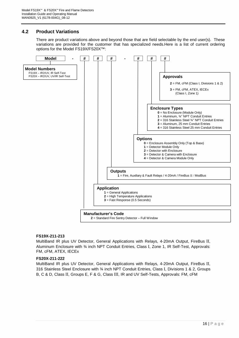
4.2 Product Variations There are product variations above and beyond those that are field selectable by the end user(s). These variations are provided for the customer that has specialized needs.Here is a list of current ordering options for the Model FS19X/FS20X™:
Model - # # # - # # #
FS19X-211-213 MultiBand IR plus UV Detector, General Applications with Relays, 4-20mA Output, FireBus II, Aluminum Enclosure with ¾ inch NPT Conduit Entries, Class I, Zone 1, IR Self-Test, Approvals: FM, cFM, ATEX, IECEx FS20X-211-222 MultiBand IR plus UV Detector, General Applications with Relays, 4-20mA Output, FireBus II, 316 Stainless Steel Enclosure with ¾ inch NPT Conduit Entries, Class I, Divisions 1 & 2, Groups B, C & D, Class II, Groups E, F & G, Class III, IR and UV Self-Tests, Approvals: FM, cFM
Model Numbers FS19X – IR2/UV, IR Self-Test
FS20X – IR2/UV, UV/IR Self-Test
Enclosure Types 0 = No Enclosure (Module Only) 1 = Aluminum, ¾” NPT Conduit Entries 2 = 316 Stainless Steel ¾” NPT Conduit Entries 3 = Aluminum, 25 mm Conduit Entries 4 = 316 Stainless Steel 25 mm Conduit Entries
Options 0 = Enclosure Assembly Only (Top & Base) 1 = Detector Module Only 2 = Detector with Enclosure 3 = Detector & Camera with Enclosure 4 = Detector & Camera Module Only
Outputs 1 = Fire, Auxiliary & Fault Relays / 4-20mA / FireBus II / ModBus
Application 1 = General Applications 2 = High Temperature Applications 3 = Fast Response (0.5 Seconds)
Manufacturer’s Code 2 = Standard Fire Sentry Detector – Full Window
Approvals 2 = FM, cFM (Class I, Divisions 1 & 2)
3 = FM, cFM, ATEX, IECEx (Class I, Zone 1)
Model FS19X™ & FS20X™ Fire and Flame Detectors Installation Guide and Operating Manual MAN0925_V1 (6178-004G)_08-12
17 | P a g e
4.3 Digital Communication Options The FS19X/FS20X Detector has a variety of Analog and RS-485 Digital Communication options that can be selected using its Rotary Switch SW3.
SW3 Position Outputs 0 4-20mA Current Sinking and FireBus II 1 4-20mA Current Sourcing and FireBus II 2 ModBus RTU and 4-20mA Current Sourcing 3 Reserved for Factory Use 4 FireBus II and 4-20mA Current Sourcing 5 through 9 Reserved for Factory Use
4.4 Test Lamps Some manufacturers claim that their detectors do not need remote testing with an external Test Lamp because it tests itself. Even though Fire Sentry Detectors also perform “through the lens” self-testing and tests themselves, Fire Sentry, in compliance with NFPA 72 codes, has developed portable test lamps for periodical “end-to-end” testing their Detectors remotely. Some of the most important functions of the remote test lamp are to ensure the Detector’s optical path is not blocked, the Detector is aimed properly at the fire threat area (that the Detector mounting bracket didn’t move or was accidentally bumped by someone), and the Detectors alarming circuitry and outputs (i.e. relays, 4-to-20 mA, open collectors, etc.) function properly. Internal Detector testing and window lens cleanliness testing cannot insure the Detector is aimed properly, that its view of the fire scene has not been blocked by something such as a newly installed pipe or duct, storage box, parked vehicle, etc., and its alarm outputs are functioning properly.
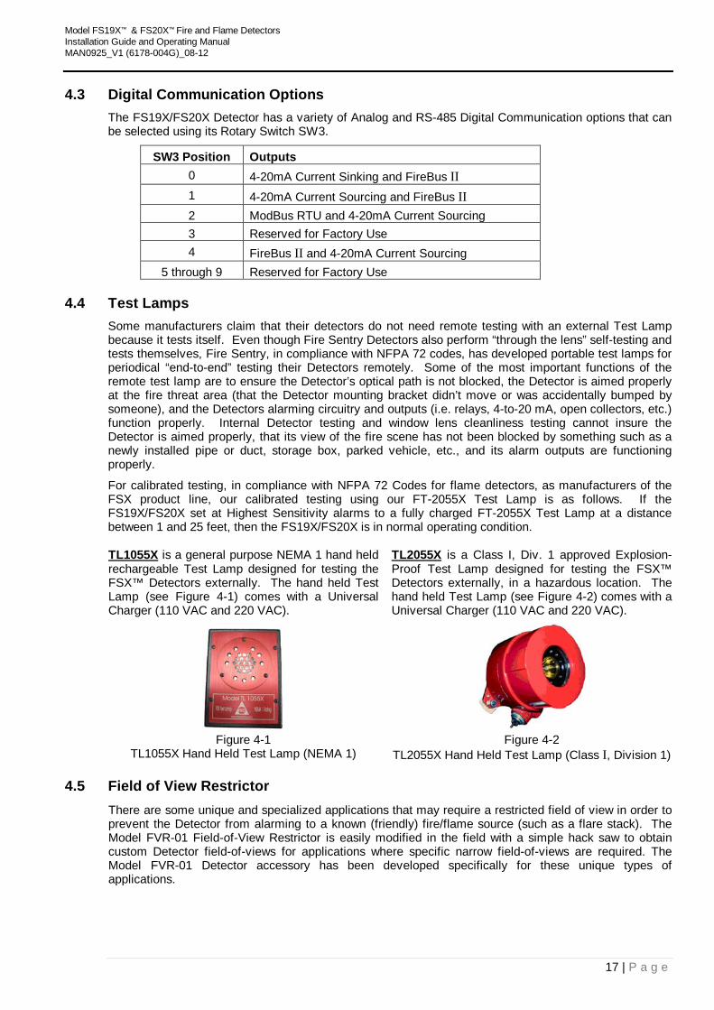
For calibrated testing, in compliance with NFPA 72 Codes for flame detectors, as manufacturers of the FSX product line, our calibrated testing using our FT-2055X Test Lamp is as follows. If the FS19X/FS20X set at Highest Sensitivity alarms to a fully charged FT-2055X Test Lamp at a distance between 1 and 25 feet, then the FS19X/FS20X is in normal operating condition. UTL1055XU is a general purpose NEMA 1 hand held rechargeable Test Lamp designed for testing the FSX™ Detectors externally. The hand held Test Lamp (see Figure 4-1) comes with a Universal Charger (110 VAC and 220 VAC).
UTL2055XU is a Class I, Div. 1 approved Explosion-Proof Test Lamp designed for testing the FSX™ Detectors externally, in a hazardous location. The hand held Test Lamp (see Figure 4-2) comes with a Universal Charger (110 VAC and 220 VAC).
Figure 4-1
TL1055X Hand Held Test Lamp (NEMA 1) Figure 4-2
TL2055X Hand Held Test Lamp (Class I, Division 1)
4.5 Field of View Restrictor There are some unique and specialized applications that may require a restricted field of view in order to prevent the Detector from alarming to a known (friendly) fire/flame source (such as a flare stack). The Model FVR-01 Field-of-View Restrictor is easily modified in the field with a simple hack saw to obtain custom Detector field-of-views for applications where specific narrow field-of-views are required. The Model FVR-01 Detector accessory has been developed specifically for these unique types of applications.
Model FS19X™ & FS20X™ Fire and Flame Detectors Installation Guide and Operating Manual MAN0925_V1 (6178-004G)_08-12
18 | P a g e
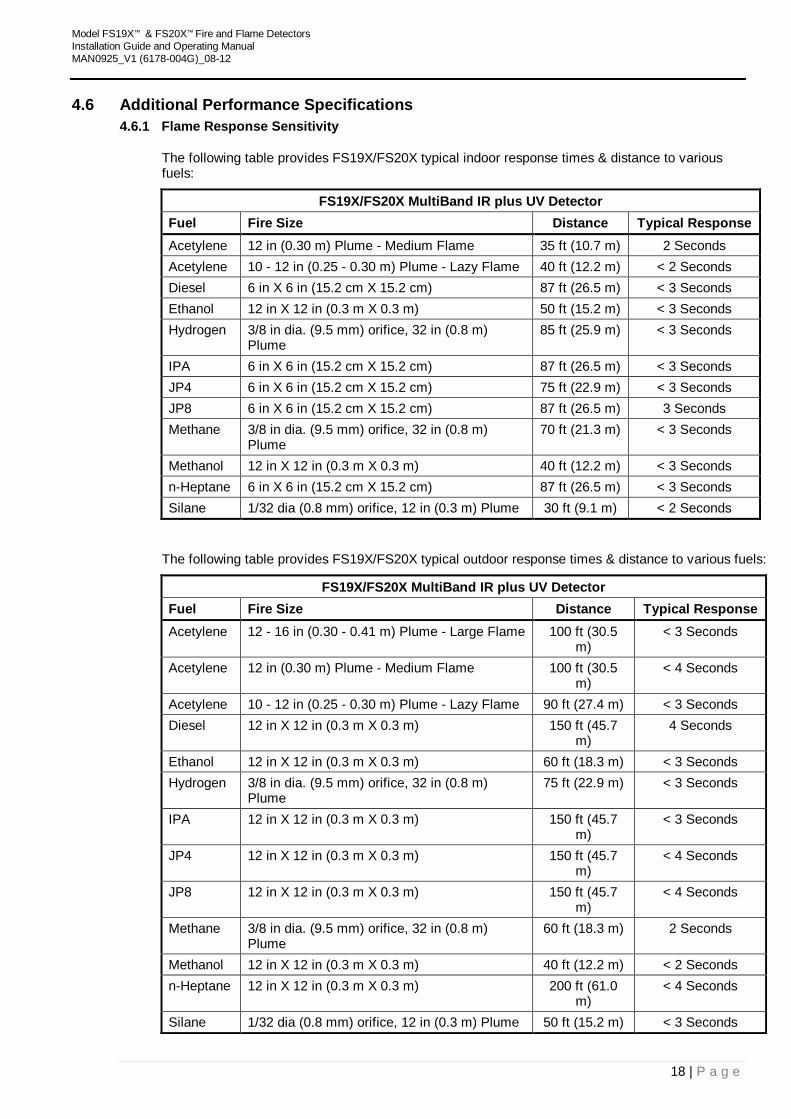
4.6 Additional Performance Specifications 4.6.1 Flame Response Sensitivity
The following table provides FS19X/FS20X typical indoor response times & distance to various fuels:
FS19X/FS20X MultiBand IR plus UV Detector Fuel Fire Size Distance Typical Response Acetylene 12 in (0.30 m) Plume - Medium Flame 35 ft (10.7 m) 2 Seconds Acetylene 10 - 12 in (0.25 - 0.30 m) Plume - Lazy Flame 40 ft (12.2 m) < 2 Seconds Diesel 6 in X 6 in (15.2 cm X 15.2 cm) 87 ft (26.5 m) < 3 Seconds Ethanol 12 in X 12 in (0.3 m X 0.3 m) 50 ft (15.2 m) < 3 Seconds Hydrogen 3/8 in dia. (9.5 mm) orifice, 32 in (0.8 m)
Plume 85 ft (25.9 m) < 3 Seconds
IPA 6 in X 6 in (15.2 cm X 15.2 cm) 87 ft (26.5 m) < 3 Seconds JP4 6 in X 6 in (15.2 cm X 15.2 cm) 75 ft (22.9 m) < 3 Seconds JP8 6 in X 6 in (15.2 cm X 15.2 cm) 87 ft (26.5 m) 3 Seconds Methane 3/8 in dia. (9.5 mm) orifice, 32 in (0.8 m)
Plume 70 ft (21.3 m) < 3 Seconds
Methanol 12 in X 12 in (0.3 m X 0.3 m) 40 ft (12.2 m) < 3 Seconds n-Heptane 6 in X 6 in (15.2 cm X 15.2 cm) 87 ft (26.5 m) < 3 Seconds Silane 1/32 dia (0.8 mm) orifice, 12 in (0.3 m) Plume 30 ft (9.1 m) < 2 Seconds
The following table provides FS19X/FS20X typical outdoor response times & distance to various fuels:
FS19X/FS20X MultiBand IR plus UV Detector Fuel Fire Size Distance Typical Response Acetylene 12 - 16 in (0.30 - 0.41 m) Plume - Large Flame 100 ft (30.5
m) < 3 Seconds
Acetylene 12 in (0.30 m) Plume - Medium Flame 100 ft (30.5 m)
< 4 Seconds
Acetylene 10 - 12 in (0.25 - 0.30 m) Plume - Lazy Flame 90 ft (27.4 m) < 3 Seconds Diesel 12 in X 12 in (0.3 m X 0.3 m) 150 ft (45.7
m) 4 Seconds
Ethanol 12 in X 12 in (0.3 m X 0.3 m) 60 ft (18.3 m) < 3 Seconds Hydrogen 3/8 in dia. (9.5 mm) orifice, 32 in (0.8 m)
Plume 75 ft (22.9 m) < 3 Seconds
IPA 12 in X 12 in (0.3 m X 0.3 m) 150 ft (45.7 m)
< 3 Seconds
JP4 12 in X 12 in (0.3 m X 0.3 m) 150 ft (45.7 m)
< 4 Seconds
JP8 12 in X 12 in (0.3 m X 0.3 m) 150 ft (45.7 m)
< 4 Seconds
Methane 3/8 in dia. (9.5 mm) orifice, 32 in (0.8 m) Plume
60 ft (18.3 m) 2 Seconds
Methanol 12 in X 12 in (0.3 m X 0.3 m) 40 ft (12.2 m) < 2 Seconds n-Heptane 12 in X 12 in (0.3 m X 0.3 m) 200 ft (61.0
m) < 4 Seconds
Silane 1/32 dia (0.8 mm) orifice, 12 in (0.3 m) Plume 50 ft (15.2 m) < 3 Seconds
Model FS19X™ & FS20X™ Fire and Flame Detectors Installation Guide and Operating Manual MAN0925_V1 (6178-004G)_08-12
19 | P a g e
4.6.2 High Temperature Response
The optional extended temperature range FS19X/FS20X Detector will respond to a one (1) square foot n-heptane reference fire at a distance of 35 feet in 2 to 5 seconds, when the temperature exceeds 85°C.
Model FS19X™ & FS20X™ Fire and Flame Detectors Installation Guide and Operating Manual MAN0925_V1 (6178-004G)_08-12
20 | P a g e
Additional Performance Specifications (continued)
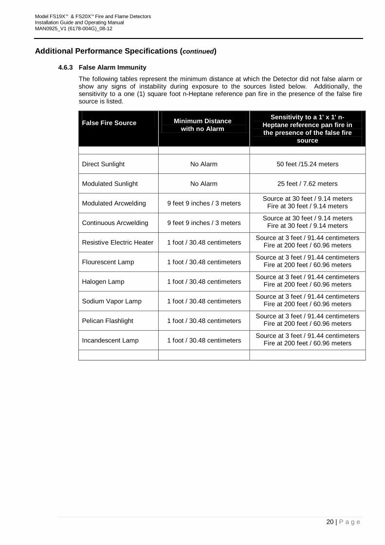
4.6.3 False Alarm Immunity
The following tables represent the minimum distance at which the Detector did not false alarm or show any signs of instability during exposure to the sources listed below. Additionally, the sensitivity to a one (1) square foot n-Heptane reference pan fire in the presence of the false fire source is listed.
False Fire Source Minimum Distance with no Alarm
Sensitivity to a 1' x 1' n-Heptane reference pan fire in the presence of the false fire
source
Direct Sunlight No Alarm 50 feet /15.24 meters
Modulated Sunlight No Alarm 25 feet / 7.62 meters
Modulated Arcwelding 9 feet 9 inches / 3 meters Source at 30 feet / 9.14 meters
Fire at 30 feet / 9.14 meters
Continuous Arcwelding 9 feet 9 inches / 3 meters Source at 30 feet / 9.14 meters
Fire at 30 feet / 9.14 meters
Resistive Electric Heater 1 foot / 30.48 centimeters Source at 3 feet / 91.44 centimeters
Fire at 200 feet / 60.96 meters
Flourescent Lamp 1 foot / 30.48 centimeters Source at 3 feet / 91.44 centimeters
Fire at 200 feet / 60.96 meters
Halogen Lamp 1 foot / 30.48 centimeters Source at 3 feet / 91.44 centimeters
Fire at 200 feet / 60.96 meters
Sodium Vapor Lamp 1 foot / 30.48 centimeters Source at 3 feet / 91.44 centimeters
Fire at 200 feet / 60.96 meters
Pelican Flashlight 1 foot / 30.48 centimeters Source at 3 feet / 91.44 centimeters
Fire at 200 feet / 60.96 meters
Incandescent Lamp 1 foot / 30.48 centimeters Source at 3 feet / 91.44 centimeters
Fire at 200 feet / 60.96 meters
Model FS19X™ & FS20X™ Fire and Flame Detectors Installation Guide and Operating Manual MAN0925_V1 (6178-004G)_08-12
21 | P a g e
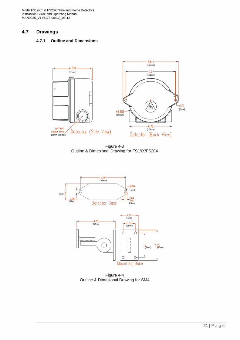
4.7 Drawings
4.7.1 Outline and Dimensions
Figure 4-3 Outline & Dimesional Drawing for FS19X/FS20X
Figure 4-4 Outline & Dimesional Drawing for SM4
Model FS19X™ & FS20X™ Fire and Flame Detectors Installation Guide and Operating Manual MAN0925_V1 (6178-004G)_08-12
22 | P a g e
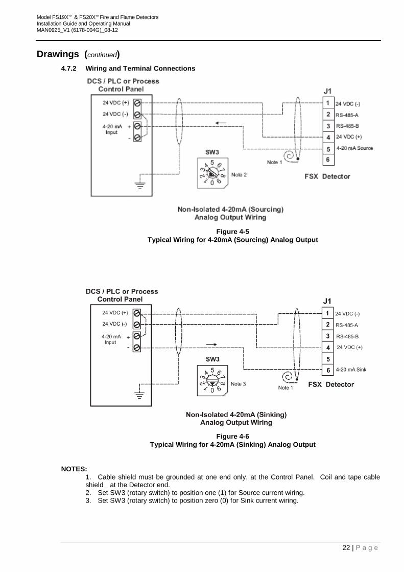
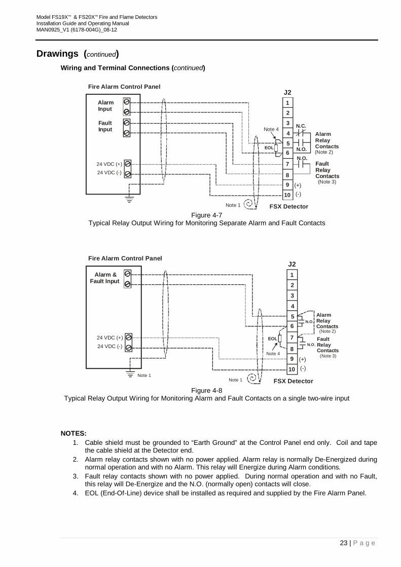
Drawings (continued) 4.7.2 Wiring and Terminal Connections
Figure 4-5
Typical Wiring for 4-20mA (Sourcing) Analog Output
Figure 4-6
Typical Wiring for 4-20mA (Sinking) Analog Output
NOTES: 1. Cable shield must be grounded at one end only, at the Control Panel. Coil and tape cable shield at the Detector end. 2. Set SW3 (rotary switch) to position one (1) for Source current wiring. 3. Set SW3 (rotary switch) to position zero (0) for Sink current wiring.
Model FS19X™ & FS20X™ Fire and Flame Detectors Installation Guide and Operating Manual MAN0925_V1 (6178-004G)_08-12
23 | P a g e
Drawings (continued) Wiring and Terminal Connections (continued)
J21
2
3
5
4
6
(-) (+)
Fire Alarm Control Panel
24 VDC (+)24 VDC (-)
FSX DetectorNote 1
7
89
10
Alarm Input
Fault Input N.C.
N.O.
AlarmRelayContacts
FaultRelayContacts
N.O.
(Note 3)
(Note 2)
Note 4
EOL
Figure 4-7
Typical Relay Output Wiring for Monitoring Separate Alarm and Fault Contacts
J21
2
3
5
4
6
(-) (+)
Fire Alarm Control Panel
24 VDC (+)24 VDC (-)
FSX DetectorNote 1
7
89
10
Alarm & Fault Input
N.O.AlarmRelayContacts
FaultRelayContacts
N.O.
(Note 3)
(Note 2)
Note 4
EOL
Note 1
Figure 4-8
Typical Relay Output Wiring for Monitoring Alarm and Fault Contacts on a single two-wire input
NOTES: 1. Cable shield must be grounded to “Earth Ground” at the Control Panel end only. Coil and tape
the cable shield at the Detector end. 2. Alarm relay contacts shown with no power applied. Alarm relay is normally De-Energized during
normal operation and with no Alarm. This relay will Energize during Alarm conditions. 3. Fault relay contacts shown with no power applied. During normal operation and with no Fault,
this relay will De-Energize and the N.O. (normally open) contacts will close. 4. EOL (End-Of-Line) device shall be installed as required and supplied by the Fire Alarm Panel.

Model FS19X™ & FS20X™ Fire and Flame Detectors Installation Guide and Operating Manual MAN0925_V1 (6178-004G)_08-12
24 | P a g e
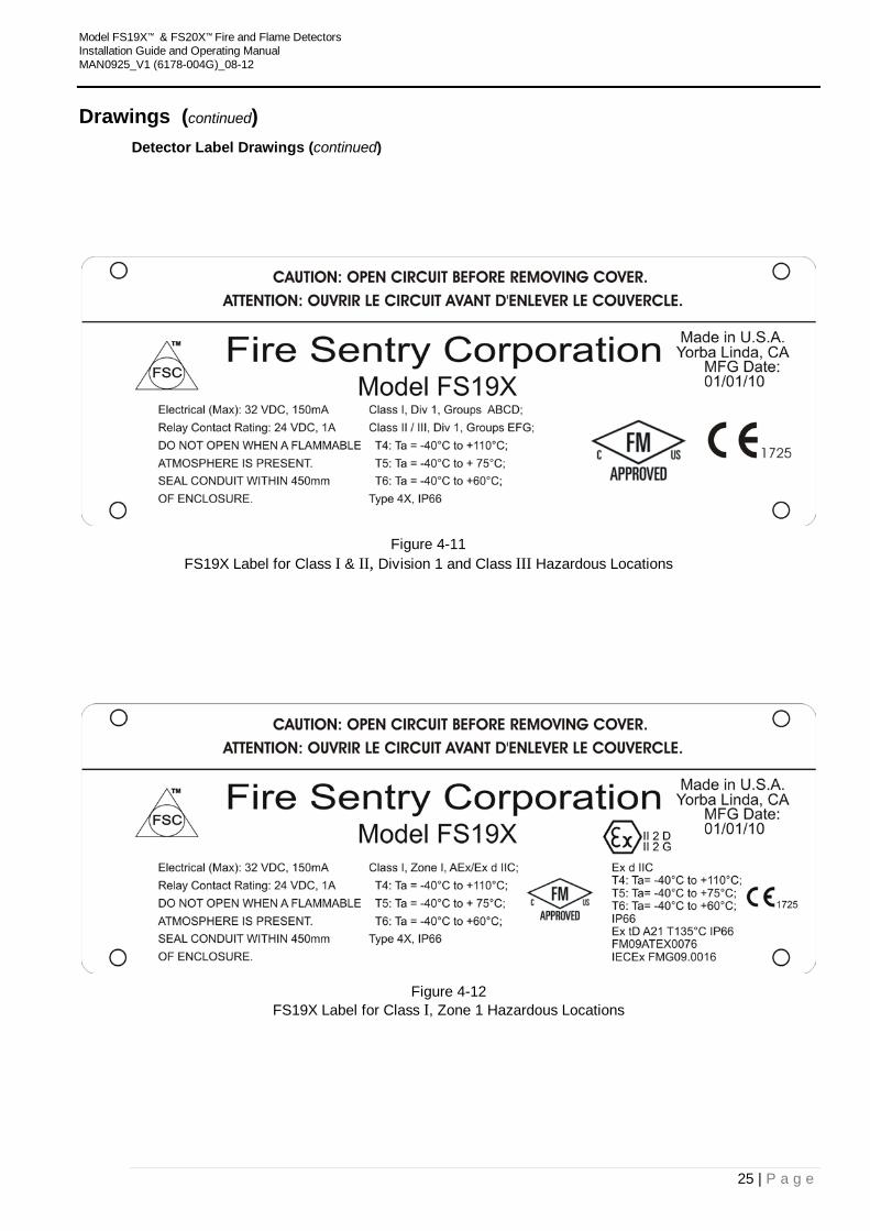
Drawings (continued) 4.7.3 Detector Label Drawings
Figure 4-9
FS20X Label for Class I & II, Division 1 and Class III Hazardous Locations
Figure 4-10
FS20X Label for Class I, Zone 1 Hazardous Locations
Model FS19X™ & FS20X™ Fire and Flame Detectors Installation Guide and Operating Manual MAN0925_V1 (6178-004G)_08-12
25 | P a g e
Drawings (continued) Detector Label Drawings (continued)
Figure 4-11
FS19X Label for Class I & II, Division 1 and Class III Hazardous Locations
Figure 4-12
FS19X Label for Class I, Zone 1 Hazardous Locations
Model FS19X™ & FS20X™ Fire and Flame Detectors Installation Guide and Operating Manual MAN0925_V1 (6178-004G)_08-12
26 | P a g e
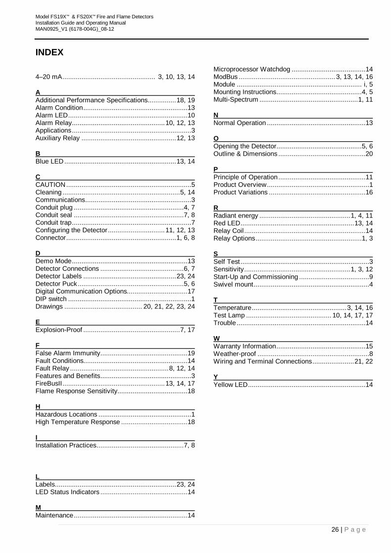
INDEX
4–20 mA ................................................. 3, 10, 13, 14
UA Additional Performance Specifications ............... 18, 19 Alarm Condition ....................................................... 13 Alarm LED ............................................................... 10 Alarm Relay ................................................. 10, 12, 13 Applications ...............................................................3 Auxiliary Relay .................................................. 12, 13
UB Blue LED ........................................................... 13, 14
UC CAUTION ..................................................................5 Cleaning .............................................................. 5, 14 Communications ........................................................3 Conduit plug .......................................................... 4, 7 Conduit seal .......................................................... 7, 8 Conduit trap ...............................................................7 Configuring the Detector .............................. 11, 12, 13 Connector .......................................................... 1, 6, 8
UD Demo Mode ............................................................. 13 Detector Connections ............................................ 6, 7 Detector Labels ................................................. 23, 24 Detector Puck ........................................................ 5, 6 Digital Communication Options................................ 17 DIP switch .................................................................1 Drawings ......................................... 20, 21, 22, 23, 24
UE Explosion-Proof ................................................... 7, 17
UF False Alarm Immunity .............................................. 19 Fault Conditions....................................................... 14 Fault Relay .................................................... 8, 12, 14 Features and Benefits ................................................3 FireBusII ...................................................... 13, 14, 17 Flame Response Sensitivity..................................... 18
UH Hazardous Locations .................................................1 High Temperature Response ................................... 18
UI Installation Practices .............................................. 7, 8
UL Labels ................................................................ 23, 24 LED Status Indicators .............................................. 14
UM Maintenance ............................................................ 14
Microprocessor Watchdog ....................................... 14 ModBus ................................................... 3, 13, 14, 16 Module .................................................................. i, 5 Mounting Instructions ............................................. 4, 5 Multi-Spectrum .................................................... 1, 11
UN Normal Operation .................................................... 13
UO Opening the Detector ............................................. 5, 6 Outline & Dimensions .............................................. 20
UP Principle of Operation .............................................. 11 Product Overview ......................................................1 Product Variations ................................................... 16
UR Radiant energy ................................................ 1, 4, 11 Red LED ............................................................ 13, 14 Relay Coil ................................................................ 14 Relay Options ........................................................ 1, 3
US Self Test ....................................................................3 Sensitivity ........................................................ 1, 3, 12 Start-Up and Commissioning .....................................9 Swivel mount .............................................................4
UT Temperature .................................................. 3, 14, 16 Test Lamp ............................................. 10, 14, 17, 17 Trouble .................................................................... 14
UW Warranty Information ............................................... 15 Weather-proof ...........................................................8 Wiring and Terminal Connections ...................... 21, 22
UY Yellow LED .............................................................. 14
Model FS19X™ & FS20X™ Fire and Flame Detectors Installation Guide and Operating Manual MAN0925_V1 (6178-004G)_08-12
27 | P a g e
Please Note: While every effort has been made to ensure accuracy in this publication, no responsibility can be accepted for errors or omissions. Data may change, as well as legislation, and you are strongly advised to obtain copies of the most recently issued regulations, standards, and guidelines. This publication is not intended to form the basis of a contract.
www.honeywellanalytics.com Contact Honeywell Analytics: Europe, Middle East, Africa, India Life Safety Distribution AG Javastrasse 2 8604 Hegnau Switzerland Tel: +41 (0)44 943 4300 Fax: +41 (0)44 943 439 India Tel: +91 124 4752700 [email protected] Americas Honeywell Analytics Inc. 405 Barclay Blvd. Lincolnshire, IL 60069 USA Tel: +1 847 955 8200 Toll free: +1 800 538 0363 Fax: +1 847 955 8210 [email protected] Asia Pacific Honeywell Analytics Asia Pacific #508, Kolon Science Valley (I) 187-10 Guro-Dong, Guro-Gu Seoul, 152-050 Korea Tel: +82 (0)2 6909 0300 Fax: +82 (0)2 2025 0329 [email protected] Technical Services EMEAI: [email protected] US: [email protected] AP: [email protected] www.honeywell.com
Issue 1 (6178-004G)_08/2012 H_MAN0925_EMEAI © 2012 Honeywell Analytics 13
065