Embed Size (px)
Citation preview
Face Recognition Terminal
Quick Start Guide
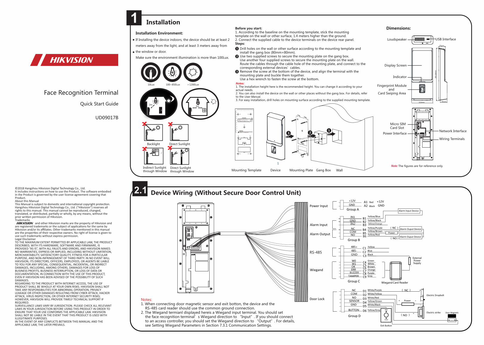
Device Wiring (Without Secure Door Control Unit)
Installation Environment:
If Installing the device indoors, the device should be at least 2
meters away from the light, and at least 3 meters away from
the window or door.
Make sure the environment illumination is more than 100Lux.
Direct Sunlight
Direct Sunlightthrough Window
Indirect Sunlightthrough Window
Dimensions:
Backlight
©2018 Hangzhou Hikvision Digital Technology Co., Ltd. It includes instructions on how to use the Product. The software embodied in the Product is governed by the user license agreement covering that Product.About this ManualThis Manual is subject to domestic and international copyright protection. Hangzhou Hikvision Digital Technology Co., Ltd. (“Hikvision”) reserves all rights to this manual. This manual cannot be reproduced, changed, translated, or distributed, partially or wholly, by any means, without the prior written permission of Hikvision. Trademarks and other Hikvision marks are the property of Hikvision and are registered trademarks or the subject of applications for the same by Hikvision and/or its affiliates. Other trademarks mentioned in this manual are the properties of their respective owners. No right of license is given to use such trademarks without express permission.Legal DisclaimerTO THE MAXIMUM EXTENT PERMITTED BY APPLICABLE LAW, THE PRODUCT DESCRIBED, WITH ITS HARDWARE, SOFTWARE AND FIRMWARE, IS PROVIDED “AS IS”, WITH ALL FAULTS AND ERRORS, AND HIKVISION MAKES NO WARRANTIES, EXPRESS OR IMPLIED, INCLUDING WITHOUT LIMITATION, MERCHANTABILITY, SATISFACTORY QUALITY, FITNESS FOR A PARTICULAR PURPOSE, AND NON-INFRINGEMENT OF THIRD PARTY. IN NO EVENT WILL HIKVISION, ITS DIRECTORS, OFFICERS, EMPLOYEES, OR AGENTS BE LIABLE TO YOU FOR ANY SPECIAL, CONSEQUENTIAL, INCIDENTAL, OR INDIRECT DAMAGES, INCLUDING, AMONG OTHERS, DAMAGES FOR LOSS OF BUSINESS PROFITS, BUSINESS INTERRUPTION, OR LOSS OF DATA OR DOCUMENTATION, IN CONNECTION WITH THE USE OF THIS PRODUCT, EVEN IF HIKVISION HAS BEEN ADVISED OF THE POSSIBILITY OF SUCH DAMAGES.REGARDING TO THE PRODUCT WITH INTERNET ACCESS, THE USE OF PRODUCT SHALL BE WHOLLY AT YOUR OWN RISKS. HIKVISION SHALL NOT TAKE ANY RESPONSIBILITIES FOR ABNORMAL OPERATION, PRIVACY LEAKAGE OR OTHER DAMAGES RESULTING FROM CYBER ATTACK, HACKER ATTACK, VIRUS INSPECTION, OR OTHER INTERNET SECURITY RISKS; HOWEVER, HIKVISION WILL PROVIDE TIMELY TECHNICAL SUPPORT IF REQUIRED. SURVEILLANCE LAWS VARY BY JURISDICTION. PLEASE CHECK ALL RELEVANT LAWS IN YOUR JURISDICTION BEFORE USING THIS PRODUCT IN ORDER TO ENSURE THAT YOUR USE CONFORMS THE APPLICABLE LAW. HIKVISION SHALL NOT BE LIABLE IN THE EVENT THAT THIS PRODUCT IS USED WITH ILLEGITIMATE PURPOSES. IN THE EVENT OF ANY CONFLICTS BETWEEN THIS MANUAL AND THE APPLICABLE LAW, THE LATER PREVAILS.
UD09017B
Note: The figures are for reference only.
10Lux >1200Lux100~850Lux
1
2
3
Notes:1. The installation height here is the recommended height. You can change it according to your actual needs.2. You can also install the device on the wall or other places without the gang box. For details, refer to the User Manual.3. For easy installation, drill holes on mounting surface according to the supplied mounting template.
Drill holes on the wall or other surface according to the mounting template and install the gang box (80mm×80mm).Use two supplied screws to secure the mounting plate on the gang box.Use another four supplied screws to secure the mounting plate on the wall.Route the cables through the cable hole of the mounting plate, and connect to the corresponding external devices’cables.Remove the screw at the bottom of the device, and align the terminal with the mounting plate and buckle them together. Use a hex wrench to fasten the screw at the bottom.
Before you start: 1. According to the baseline on the mounting template, stick the mounting template on the wall or other surface, 1.4 meters higher than the ground.2. Connect the supplied cable to the device terminals on the device rear panel.Steps:
3m
Gang BoxMounting Template
13 2
孔1 孔1
孔2
孔2 孔2
孔3
孔2
孔3
孔1 孔1
推荐距地面1.40米,可根据身高进行调整。
将该贴纸贴在要安装的位置,根据图标来做打孔、布
线等操作;
产品最大尺寸为该贴纸最大轮廓边向外偏移10mm;
孔1:墙面固定孔;孔2:暗盒固定孔;孔3:出线孔。
Mounting PlateDevice Wall
Display Screen
Fingerprint Moduleand
Card Swiping Area
Indicator
Loudspeaker
Micro SIM Card Slot
Network Interface
USB Interface
35mm
281.
18m
m
113mm 45mm
Wiring Terminals
Power Interface
2m
Notes: 1. When connecting door magnetic sensor and exit botton, the device and the RS-485 card reader should use the common ground connection.2. The Wiegand termianl displayed hereis a Wiegand input terminal. You should set the face recognition terminal’s Wiegand direction to “Input”. If you should connect to an access controller, you should set the Wiegand direction to “Output”. For details, see Setting Wiegand Parameters in Section 7.3.1 Communication Settings.
1 Installation
22.1

Activation
Activating via Device
Power on and wire the network cable after installation.
You should activate the device before the first login.
If the device is not activated yet, it will enter the Activate Device page
after powering on.
1. Create a password and confirm the password.
2. Tap Activate to activate the device.
Note: For other activation methods, see the device user manual.
1. Tap the settings icon at the lower right corner of the initial page and input the activation password to enter the main page.
2. Enter the User Management page, tap + to enter the Add User page.
4. Tap Face and collect the face information according to the instructions. You can view the captured picture at the upper right corner of the page. Make sure the face picture is in good quality and size. For details about the tips and positions when collecting or comparing the face picture, see the contents on the right.5. If the picture is in good condition, tap Save to save the picture. Or tap Try Again to take another face picture.
6. Tap to save the settings. Go back to the initial page to start authentication. For other authentication methods, see the device user manual.
Adding Face Information Positions When Collecting/Comparing Face Picture(Recommended Distance: 0.5m)
Tips When Collecting/Comparing Face PictureExpression
Posture
Size
1.4m
0.5m
1.4m
Too High
Too Low
Too Close Too Far
1.4m
0.5m
1.4m
Make sure your face is in the middle of the collecting window.
Correct Tilt RaiseSide Bow
0.5m 0.5m
激活设备Activate Device
Password
Confirm
8 to 16 characters.
Passwords should be the same.
Activate
Recommended Height:
1.43m to 1.90m
Correct Too Close Too Far
1.4m
Too Close
Too FarCorrect
0.5m
Height:1.43m to 1.90m
Move Back and Forth
Note: Two or more of the following characters are allowed: digit, number, and symbol.
Note: The device will not support the fingerprint collection function if the device model contains F.
Recommended:
Use 1:1 Face Matching when the face is hard to recognize.Use other authentication methods if the device if affected by the light or other items.1:1 Matching: The device will compare the captured face picture with the ones in the database.1:N Matching: The device will compare the captured face picture with the input employee ID linked face picture.Notes: If you require a higher security level, do not use single authentication.If you adopt multiple authentications mode, you should authenticate other methods before authenticating face.
Regulatory Information
This product and - if applicable - the supplied accessories too are marked with "CE" and comply therefore with the applicable harmonized European standards listed under the RE Directive 2014/53/EU, the EMC Directive 2014/30/EU, the RoHS Directive 2011/65/EU.
2012/19/EU (WEEE directive): Products marked with this symbol cannot be disposed of as unsorted municipal waste in the European Union. For proper recycling, return this product to your local supplier upon the purchase of equivalent new equipment, or dispose of it at designated collection points. For more information see: www.recyclethis.info
2006/66/EC (battery directive): This product contains a battery that cannot be disposed of as unsorted municipal waste in the European Union. See the product documentation for specific battery information. The battery is marked with this symbol, which may include lettering to indicate cadmium (Cd), lead (Pb), or mercury (Hg). For proper recycling, return the battery to your supplier or to a designated collection point. For more information see: www.recyclethis.info
Industry Canada ICES-003 ComplianceThis device meets the CAN ICES-3 (B)/NMB-3(B) standards requirements. This device complies with Industry Canada licence-exempt RSS standard(s). Operation is subject to the following two conditions: (1) this device may not cause interference, and(2) this device must accept any interference, including interference that may cause undesired operation of the device.Le présent appareil est conforme aux CNR d'Industrie Canada applicables aux appareils radioexempts de licence. L'exploitation est autorisée aux deux conditions suivantes :(1) l'appareil ne doit pas produire de brouillage, et(2) l'utilisateur de l'appareil doit accepter tout brouillage radioélectrique subi, même si le brouillage est susceptible d'en compromettre le fonctionnement.Under Industry Canada regulations, this radio transmitter may only operate using an antenna of a type and maximum (or lesser) gain approved for the transmitter by Industry Canada. To reduce potential radio interference to other users, the antenna type and its gain should be so chosen that the equivalent isotropically radiated power (e.i.r.p.) is not more than that necessary for successful communication.Conformément à la réglementation d'Industrie Canada, le présent émetteur radio peutfonctionner avec une antenne d'un type et d'un gain maximal (ou inférieur) approuvé pour l'émetteur par Industrie Canada. Dans le but de réduire les risques de brouillage radioélectrique à l'intention des autres utilisateurs, il faut choisir le type d'antenne et son gain de sorte que la puissance isotrope rayonnée équivalente (p.i.r.e.) ne dépasse pas l'intensité nécessaire à l'établissement d'une communication satisfaisante.This equipment should be installed and operated with a minimum distance 20cm between the radiator and your body.Cet équipement doit être installé et utilisé à une distance minimale de 20 cm entre le radiateur et votre corps.
FCC ConditionsThis device complies with part 15 of the FCC Rules. Operation is subject to the following two conditions:1. This device may not cause harmful interference.2. This device must accept any interference received, including interference that may cause undesired operation.EU Conformity Statement
FCC InformationPlease take attention that changes or modification not expressly approved by the party responsible for compliance could void the user’s authority to operate the equipment.FCC compliance: This equipment has been tested and found to comply with the limits for a Class B digital device, pursuant to part 15 of the FCC Rules. These limits are designed to provide reasonable protection against harmful interference in a residential installation. This equipment generates, uses and can radiate radio frequency energy and, if not installed and used in accordance with the instructions, may cause harmful interference to radio communications. However, there is no guarantee that interference will not occur in a particular installation. If this equipment does cause harmful interference to radio or television reception, which can be determined by turning the equipment off and on, the user is encouraged to try to correct the interference by one or more of the following measures:—Reorient or relocate the receiving antenna.—Increase the separation between the equipment and receiver.—Connect the equipment into an outlet on a circuit different from that to which the receiver is connected.—Consult the dealer or an experienced radio/TV technician for help.This equipment should be installed and operated with a minimum distance 20cm between the radiator and your body.
Use only power supplies listed in the user instructions:
Model Manufacturer Standard
C2000IC12.0-24P-DE
C2000IC12.0-24P-GB
MOSO Power Supply Technology Co., Ltd. CEE
MOSO Power Supply Technology Co., Ltd. BS
Device Wiring (With Secure Door Control Unit)
Keep your expression naturally when collecting or comparing face
pictures, just like the expression in the picture on the right.
In order to get a good quality and accurate face picture, position your
face looking at the camera when collecting or comparing face pictures.
Do not wear hat, sunglasses, or other accessories
that can affect the facial recognition function.
Do not make your hair cover your eyes, ears, etc.
and heavy makeup is not allowed.
STRONG PASSWORD RECOMMENDED– We highly recommend you create a strong password of your own choosing (using a minimum of 8 characters, including upper case letters, lower case letters, numbers, and special characters) in order to increase the security of your product. And we recommend you reset your password regularly, especially in the high security system, resetting the password monthly or weekly can better protect your product.
Secure Door Control UnitWiring Terminal
Note: The secure door control unit should connect to an external power supply seperately.
Exit Button
Power Input
SENSOR
BUTTON
B1B2
B3B4
Green/BrownBlack
Green/BlackBlack
Lock Output
NC C1C2C3
COMNCWhite/Purple
White/BlackWhite/Red
RedBlack Door Magnetic
Exit Button
NO
Power
Electric Dropbolt
Electric Strike
Sensor Input
Face Recognition Terminal
4
2.2 3
Scan the QR code to get the user manual for detailed inforamtion. Note that mobile data charges may apply if Wi-Fi is unavailable.