Embed Size (px)
Citation preview

E-1
MODEL NUMBERS: 39EB500ARA 39EB500GRA 39EB500GRS
BUILT IN ELECTRIC FIREPLACE
INSTALLATION GUIDE
CONSUMER SAFETY INFORMATIONPLEASE READ THIS MANUAL BEFORE INSTALLING THIS APPLIANCE
WARNINGIF THE INFORMATION IN THIS MANUAL IS NOT FOLLOWED,
AN ELECTRIC SHOCK OR FIRE MAY RESULT CAUSINGPROPERTY DAMAGE, PERSONAL INJURY OR LOSS OF LIFE.DO NOT STORE OR USE GASOLINE OR OTHER FLAMMABLE
VAPORS AND LIQUIDS IN THE VICINITY OF THISOR ANY OTHER APPLIANCE.
Thank you and congratulations on your purchase of a Classic Flame fireplace.Please read the installation instructions before installing and operatingthis appliance.
IMPORTANT: Read all instructions and warnings carefully before starting installation.Failure to follow these instructions may result in a possible electric shock, firehazard and/or injury and will void the warranty.
For Customer Service:E-Mail: [email protected] English Call: 866-661-1218En Français Call: 866-374-9203En Español Call: 866-661-1218
Twin-Star International, Inc. Delray Beach, FL 33445
Made in ChinaPrinted in China
© 2011, Twin-Star International, Inc.
U.S.A.
LISTINGS AND CODE APPROVALSTHE BUILDERS BOX SERIES HAS BEEN TESTED AND APPROVED IN ACCORDANCE WITH THE
CSA, No.220391, STANDARDS FOR FIXED AND LOCATIONDEDICATED ELECTRIC ROOM HEATERS.
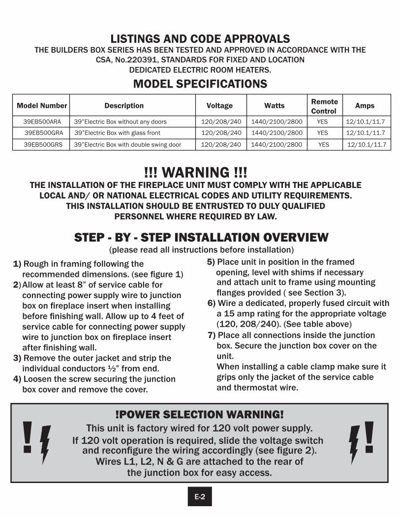
MODEL SPECIFICATIONS
!!! WARNING !!!THE INSTALLATION OF THE FIREPLACE UNIT MUST COMPLY WITH THE APPLICABLE
LOCAL AND/ OR NATIONAL ELECTRICAL CODES AND UTILITY REQUIREMENTS.THIS INSTALLATION SHOULD BE ENTRUSTED TO DULY QUALIFIED
PERSONNEL WHERE REQUIRED BY LAW.
!POWER SELECTION WARNING!This unit is factory wired for 120 volt power supply.
If 120 volt operation is required, slide the voltage switch and reconfigure the wiring accordingly (see figure 2).
Wires L1, L2, N & G are attached to the rear ofthe junction box for easy access.
! !
1) Rough in framing following the recommended dimensions. (see figure 1)2) Allow at least 8” of service cable for
connecting power supply wire to junction box on fireplace insert when installing
before finishing wall. Allow up to 4 feet of service cable for connecting power supply wire to junction box on fireplace insert
after finishing wall. 3) Remove the outer jacket and strip the
individual conductors ½” from end.4) Loosen the screw securing the junction
box cover and remove the cover.
5) Place unit in position in the framed opening, level with shims if necessary and attach unit to frame using mounting flanges provided ( see Section 3).
6) Wire a dedicated, properly fused circuit with a 15 amp rating for the appropriate voltage (120, 208/240). (See table above)
7) Place all connections inside the junction box. Secure the junction box cover on the unit.When installing a cable clamp make sure it grips only the jacket of the service cable and thermostat wire.
STEP - BY - STEP INSTALLATION OVERVIEW(please read all instructions before installation)
E-2
Model Number Description Voltage Watts Amps
39EB500ARA 39”Electric Box without any doors 120/208/240 1440/2100/2800 YES 12/10.1/11.7
Remote Control
39EB500GRA 39”Electric Box with glass front 120/208/240 1440/2100/2800 YES 12/10.1/11.7
39EB500GRS 39”Electric Box with double swing door 120/208/240 1440/2100/2800 YES 12/10.1/11.7
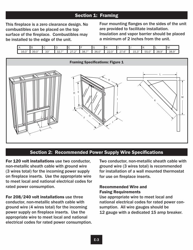
Framing Specifications: Figure 1
This fireplace is a zero clearance design. No combustibles can be placed on the topsurface of the fireplace. Combustibles maybe installed to the edge of the unit.
For 120 volt installations use two conductor, non-metallic sheath cable with ground wire(3 wires total) for the incoming power supply on fireplace inserts. Use the appropriate wire to meet local and national electrical codes for rated power consumption.
For 208/240 volt installations use threeconductor, non-metallic sheath cable with ground wire (4 wires total) for the incoming power supply on fireplace inserts. Use the appropriate wire to meet local and national electrical codes for rated power consumption.
A B C D E F G H I J K L M
D E
FG
H
I
J
L
KM
Four mounting flanges on the sides of the unit are provided to facilitate installation. Insulation and vapor barrier should be placed a minimum of 2 inches from the unit.
Two conductor, non-metallic sheath cable with ground wire (3 wires total) is recommended for installation of a wall mounted thermostat for use on fireplace inserts.
Recommended Wire andFusing RequirementsUse appropriate wire to meet local andnational electrical codes for rated power con-sumption. All wire gauges should be 12 gauge with a dedicated 15 amp breaker.
Section 2: Recommended Power Supply Wire Specifications
Section 1: Framing
E-3
16.0” 39.0” 33” 32.7” 27.2” 38.7” 36.0” 22.0” 27.6” 15.3” 55.0” 38.9” 38.9”
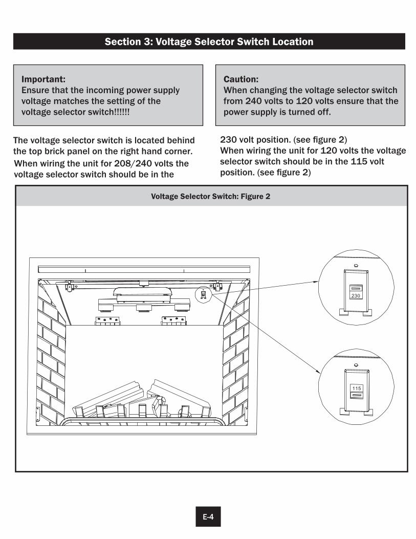
Voltage Selector Switch: Figure 2
The voltage selector switch is located behind the top brick panel on the right hand corner.
Section 3: Voltage Selector Switch Location
When wiring the unit for 208/240 volts the voltage selector switch should be in the
230 volt position. (see figure 2)When wiring the unit for 120 volts the voltage selector switch should be in the 115 voltposition. (see figure 2)
Caution:When changing the voltage selector switch from 240 volts to 120 volts ensure that the power supply is turned off.
Important:Ensure that the incoming power supply voltage matches the setting of thevoltage selector switch!!!!!!
E-4
230
115
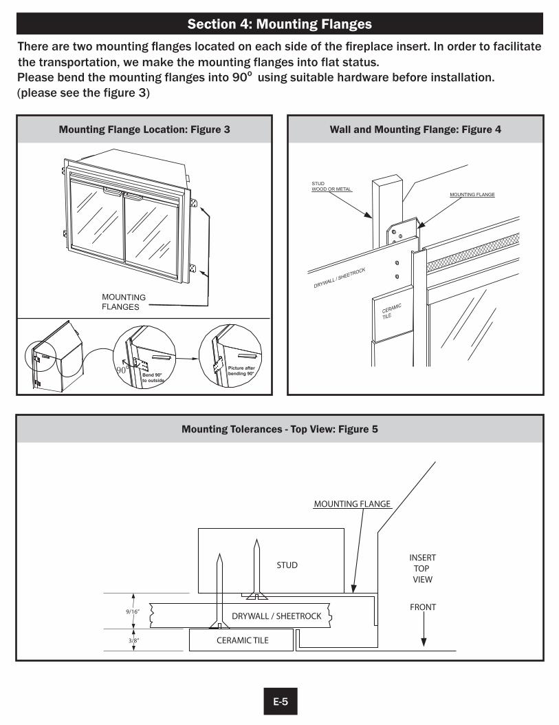
Mounting Flange Location: Figure 3
NITNUOM GEGNALF S
Wall and Mounting Flange: Figure 4
Mounting Tolerances - Top View: Figure 5
STUDWOOD OR METAL
MOUNTING FLANGE
RD WYLLA
EEHS /
CORTK
MARECIC
ELIT
DRYWALL / SHEETROCK
CERAMIC TILE
STUD
9/16”
3/8”
MOUNTING FLANGE
INSERTTOPVIEW
FRONT
Section 4: Mounting Flanges
E-5
Please bend the mounting flanges into 90o using suitable hardware before installation. (please see the figure 3)
There are two mounting flanges located on each side of the fireplace insert. In order to facilitate
90o
Bend 90o to outside
Picture after bending 90o
the transportation, we make the mounting flanges into flat status.
JUNCTION BOX
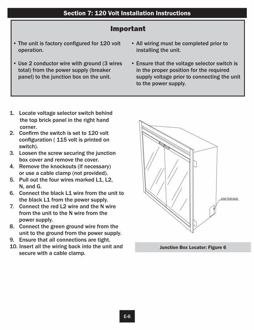
1. Locate voltage selector switch behind the top brick panel in the right hand corner. 2. Confirm the switch is set to 120 volt configuration ( 115 volt is printed on
switch).3. Loosen the screw securing the junction box cover and remove the cover.4. Remove the knockouts (if necessary) or use a cable clamp (not provided).5. Pull out the four wires marked L1, L2, N, and G.6. Connect the black L1 wire from the unit to
the black L1 from the power supply.7. Connect the red L2 wire and the N wire from the unit to the N wire from the power supply.8. Connect the green ground wire from the
unit to the ground from the power supply.9. Ensure that all connections are tight.10. Insert all the wiring back into the unit and secure with a cable clamp.
Section 7: 120 Volt Installation Instructions
Important
• The unit is factory configured for 120 volt operation.
• Use 2 conductor wire with ground (3 wires total) from the power supply (breaker panel) to the junction box on the unit.
• All wiring must be completed prior toinstalling the unit.
• Ensure that the voltage selector switch is in the proper position for the required supply voltage prior to connecting the unit to the power supply.
Junction Box Locator: Figure 6
E-6
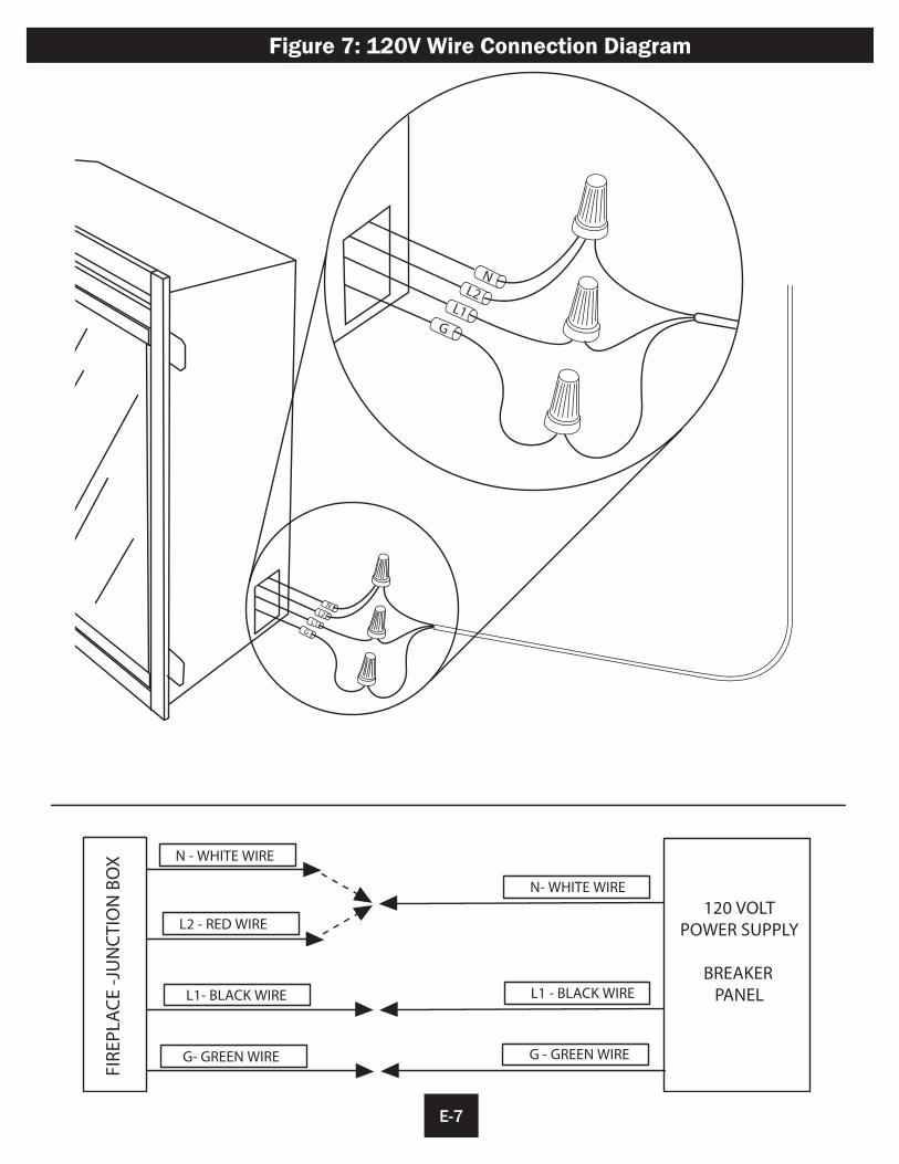
N - WHITE WIRE
L2 - RED WIRE
L1- BLACK WIRE
G- GREEN WIRE
N- WHITE WIRE
L1 - BLACK WIRE
G - GREEN WIRE
FIR
EPLA
CE
-JU
NC
TIO
N B
OX
120 VOLTPOWER SUPPLY
BREAKER PANEL
NL2
L1G
NL2
L1G
Figure 7: 120V Wire Connection Diagram
E-7
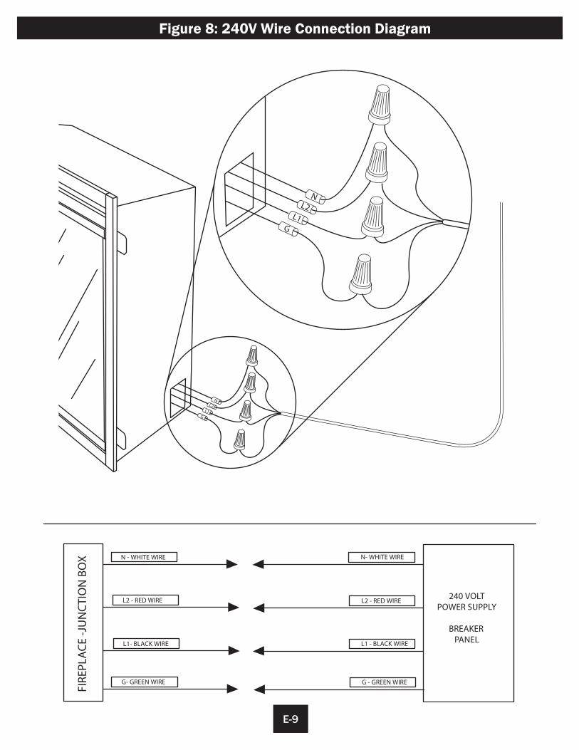
JUNCTION BOX
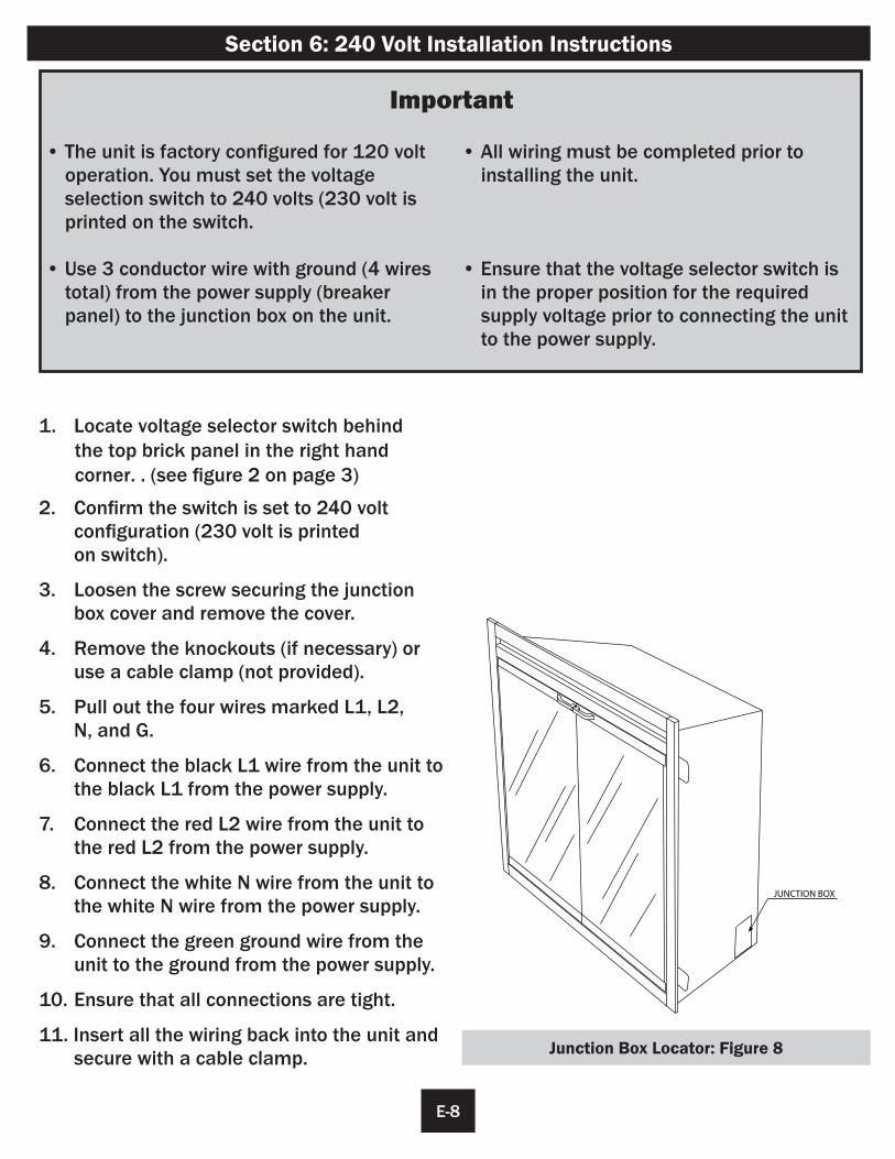
1. Locate voltage selector switch behind the top brick panel in the right hand corner. . (see figure 2 on page 3)
2. Confirm the switch is set to 240 volt configuration (230 volt is printed on switch).
3. Loosen the screw securing the junction box cover and remove the cover.
4. Remove the knockouts (if necessary) or use a cable clamp (not provided).
5. Pull out the four wires marked L1, L2, N, and G.
6. Connect the black L1 wire from the unit to the black L1 from the power supply.
7. Connect the red L2 wire from the unit to the red L2 from the power supply.
8. Connect the white N wire from the unit to the white N wire from the power supply.
9. Connect the green ground wire from the unit to the ground from the power supply.
10. Ensure that all connections are tight.
11. Insert all the wiring back into the unit and secure with a cable clamp.
Section 6: 240 Volt Installation Instructions
Important
• The unit is factory configured for 120 volt operation. You must set the voltage
selection switch to 240 volts (230 volt is printed on the switch.
• Use 3 conductor wire with ground (4 wires total) from the power supply (breaker panel) to the junction box on the unit.
• All wiring must be completed prior toinstalling the unit.
• Ensure that the voltage selector switch is in the proper position for the required supply voltage prior to connecting the unit to the power supply.
Junction Box Locator: Figure 8
E-8
N - WHITE WIRE
L2 - RED WIRE
L1- BLACK WIRE
G- GREEN WIRE
N- WHITE WIRE
L1 - BLACK WIRE
G - GREEN WIRE
FIR
EPLA
CE
-JU
NC
TIO
N B
OX
240 VOLTPOWER SUPPLY
BREAKER PANEL
L2 - RED WIRE
NL2
L1G
NL2
L1G
E-9
Figure 8: 240V Wire Connection Diagram
TS-0
824L
IGH
TTS
-082
4LIG
HT
TS-0
824L
IGH
TTS
-082
4LIG
HT
TS-0
824L
IGH
TTS
-082
4LIG
HT
TS-0
824L
IGH
TTS
-082
4LIG
HT
TS-0
824L
IGH
TTS
-082
4LIG
HT
MO
TO
R
PLU
G
TS-0824LIGHT TS-0824LIGHT TS-0824LIGHT
L2N L1
MA
INPC
B
BLU
E
LED
RE
CE
IVE
R
DIS
PLA
YN
TC
DO
WN
LIG
HT
FL
AM
EL
ED
TS
-39
EB
-DR
IVE
R
CO
NT
RO
LP
AN
EL
TS
-E25
-LO
G-D
POW
ERSW
ITC
H
GN
D
115-
230v
SW
ITC
H
E-10
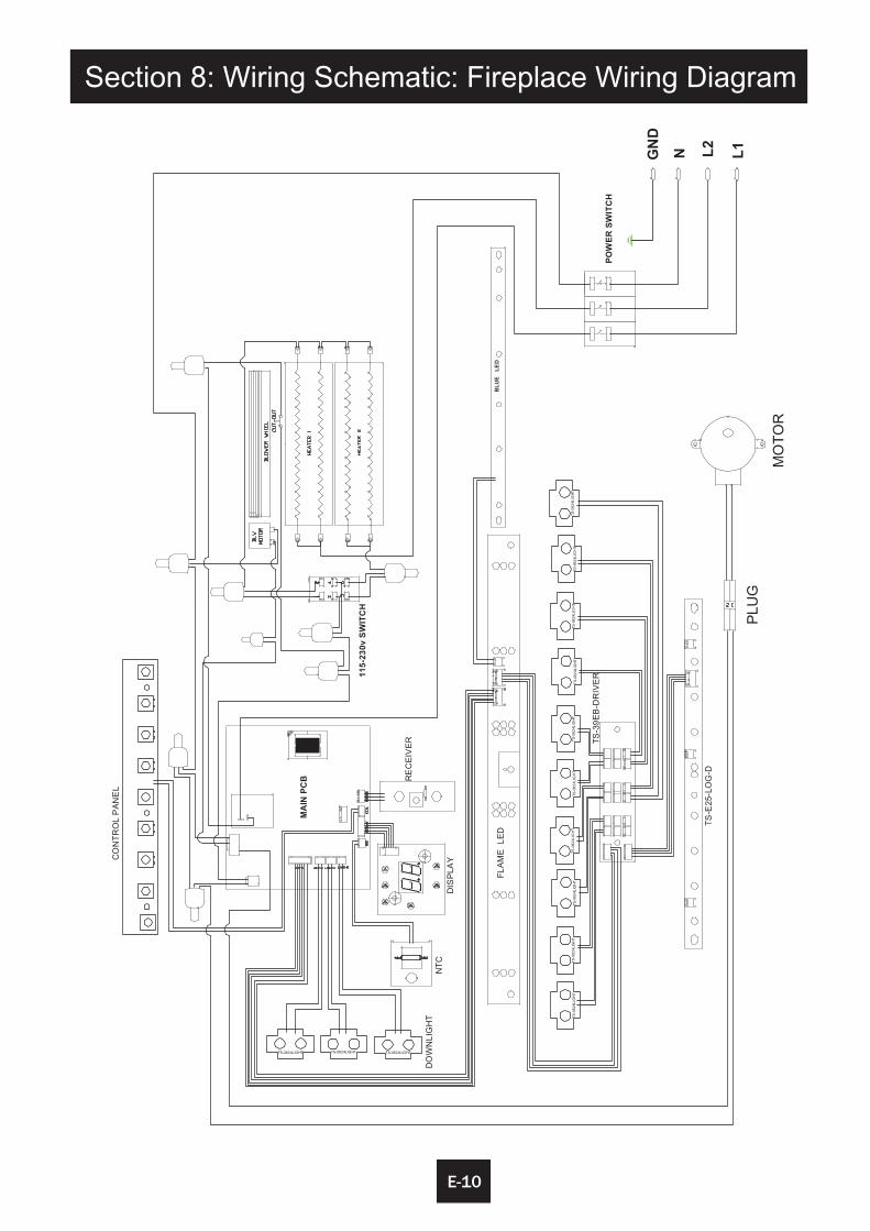
Section 8: Wiring Schematic: Fireplace Wiring Diagram