Embed Size (px)
Citation preview
2000 American Honda Motor Co., Inc. – All Rights Reserved Y0581B3 8000X-S5D-C200 1 of 24
INSTALLATIONINSTRUCTIONS
Accessory Application Publications No.
Issue DateAIR CONDITIONER CIVIC2- AND 4-DOOR
OCT 2000
AII 21888-22262
What’s New
The A/C kit and instructions for the 2001 Civicare all new. Follow these instructions carefully.
TOOLS AND SUPPLIES REQUIRED
Duct tapeHacksaw bladeTrim clip removerOpen-end wrench setScrewdriversSocket wrench setTorque wrenchTension gaugeRefrigerant oil (R-12 mineral oil or R-134a PAG oil)Fender, floor, and seat coversHFC-134a refrigerant recovery/recycling/charging
stationGlovesEye protection (face shield, or safety goggles)Electronic leak detector
NOTICE
� Use only HFC-134a in this system; do notuse CFC 12 (Freon); do not install partsdesigned for use in a CFC system.
� Use a charging station. A/C chargingstations and refrigerant recovery/recyclingstations minimize the release of CFCs andHFCs to the atmosphere. Use them for all A/Ccharging and service work according to themanufacturers’ instructions.
� Do not overcharge. This system requiresonly the amount of HFC-134a refrigerantshown below. If you overcharge the system,the engine and the A/C will malfunction.
500 to 550 grams
0.50 to 0.55 kilograms
1.1 to 1.2 pounds
17.6 to 19.4 ounces
INSTALLATIONBefore You Begin:
������������� ������������������������� ���� ������� ����������������� ��������� ����������������� ����������������������� �������������������������������������� �������������������������������� ��������� ����������������������������������� ���� ��
� Make sure you have the anti-theft code forthe audio system.
� Write down the customer’s radio stationpresets; the radio memory will be erasedwhen you disconnect the battery.
� Make sure you install the right part. Use theillustrations on pages 2 and 3 as a guide tocheck the parts before you install them.
� Don’t remove plugs and caps from fittingsuntil the parts are ready to connect. Thiswill keep out moisture and dirt which couldcause wear and damage.
During Installation:� Before you connect any line or hose,
check and lube its O-ring. Make sure theO-ring is on the fitting, put a few drops ofrefrigerant oil on the O-ring, then connect thefitting.
� You may use either type of refrigerant oil tolubricate O-rings and fittings.
� If you add or replace refrigerant oil in thesystem, use only this PAG oil: Sanden SP-10,P/N 38897-P13-A01.
� Route and secure the lines and hosesproperly; maintain clearance between themand surrounding parts.
� Use two wrenches to tighten or loosenfittings; hold one fitting in place while youtighten the other one against it.
NOTICE Don’t overtighten; you coulddamage the fittings. Before you tighten afitting, check the torque listed for it. If leaksare caused by faulty O-rings, overtighteningthe fitting won’t help.
� Before you connect each electricalconnector, check its terminals. Make surethe terminals aren’t bent or out of place.
Rep
lace
pag
es 1
, 2, 2
3, a
nd
24
wit
h t
hes
e re
vise
d p
ages
.
�������������
�����������
�������
�����������
�� ���������
���������� ��
������������
�����������
�� ���������
�������
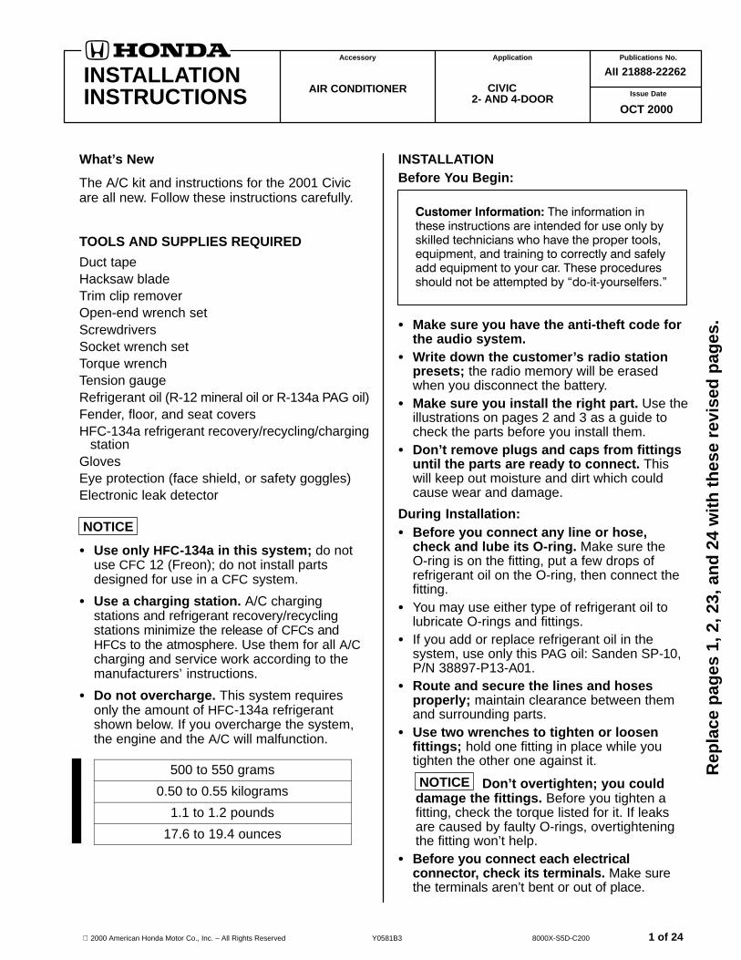
�������������������������39794-S0K-A01
2000 American Honda Motor Co., Inc – All Rights Reserved2 of 24
����� ���� ��� ��������
������ !"#$ %&�'
��( )*++"�
,-�'"��+"�
����� !"#$
�*#+ ��. '"&&$� /�&+$� �
�*#+ ��. '"&&$� /�&+$� 0
,-�'"��+"� #$�#"�
�����������
�����������
������������
�����������
�� ���������
�� ���������
���������� ��
�
�
�
�
�
�
�
�1��$ +�$#
("�.$�#$� /�� �##$2)&3
("2'�$##"�
("2'�$##"� )$&+
�$�+ ��#*&�+"�
��4!+ %"�.$�#$� )��%5$+
6$/+ %"�.$�#$� )��%5$+
�*%+�"� &��$
��#%!��4$ !"#$
��( #*%+�"� &��$ ��. �$%$�-$� &��$ 0
("�.$�#$� &��$
�$%$�-$� &��$
�$%$�-$�
�*%+�"� !"#$ %&�2' �
�*%+�"� !"#$ )��%5$+
�*%+�"� &��$ )��%5$+
�$%$�-$� &��$ %&�' �
�$%$�-$� &��$ %&�' 0
��( 7��$ !���$##
8&��4$ )"&+#9 � : ��� 22
��"*�. )"&+9 � : � 22 ;)��##�%"&"�$.<
����+ %*++��4 �*+9 � 22 ;3$&&"7�+��+$.<
1�#!$��)"&+9 � : � 22 ;3$&&"7�+��+$.<
1�#!$��)"&+#9 � : �� 22 ;4��3�%"&"�$.<
8&��4$ �*+#9 � 22 ;4��3�%"&"�$.<
8&��4$ )"&+#9 � : � 22 ;3$&&"7�+��+$.<
8&��4$ )"&+#9 � : � 22 ;3$&&"7�+��+$.<
8&��4$ )"&+9 � : �� 22 ;3$&&"7�+��+$.<
�����1�����
�������==����
�������6=����
�� ���6�����
�� ����6=����
������������
�������������
�������������
�������������
�����������
�������������
�������������
�������������
�������������
�������������
�������������
�������������
������=�����
�������������
����������
������,�����
������>�����
������������
�������������
����������
�����������
�����������
������������
�
�
�
�
�
�
�
�
�
�
�
�
�
�
�
�
�
�
�
�
�
�
�
�
��"7$� �$&�3 ;��<
��/"�2�+�"� &�)$& ;(���.�<
��/"�2�+�"� &�)$& ;���<
��( 5�+ �.$�+�/�%�+�"� &�)$&
� ����?����
�������������
�������������
������������
�
�
�
2000 American Honda Motor Co., Inc – All Rights Reserved 3 of 24
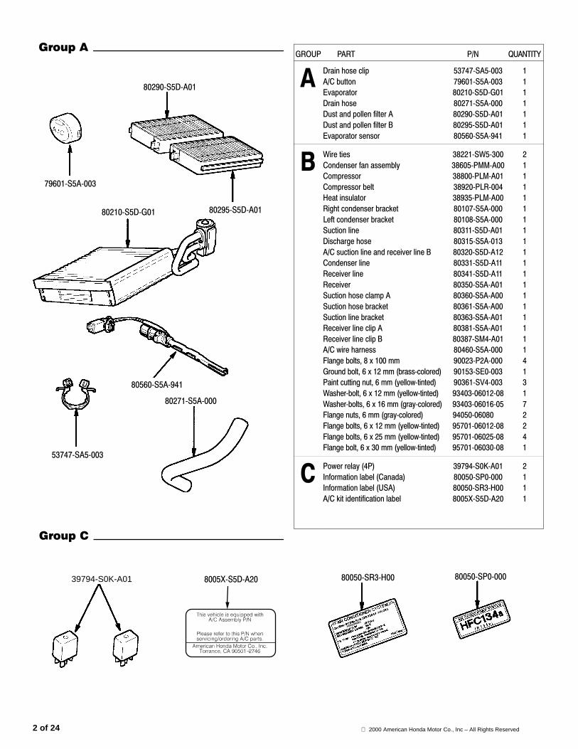
�������
�������������
������������� ������������
������������������������
�������������
������������� ������������
�������������
����������������������������
������������������������
������������� ������������
�������������
�������������
�������������
������������
���������������������������
������������
�������������
�������������
������������
�������������
�������������
�������������
������ �������������������
����������������������������
�������������
� ������������������������
������!������
������������� ���"��������
����������������������������
�#��$$���������������%�����
��������������������� ����
����������������������������
������������� ������������
38221–SW5–300
������!&�����
�����!������
�������"��������������������
�����!&�����
�����!&'���
2000 American Honda Motor Co., Inc – All Rights Reserved4 of 24
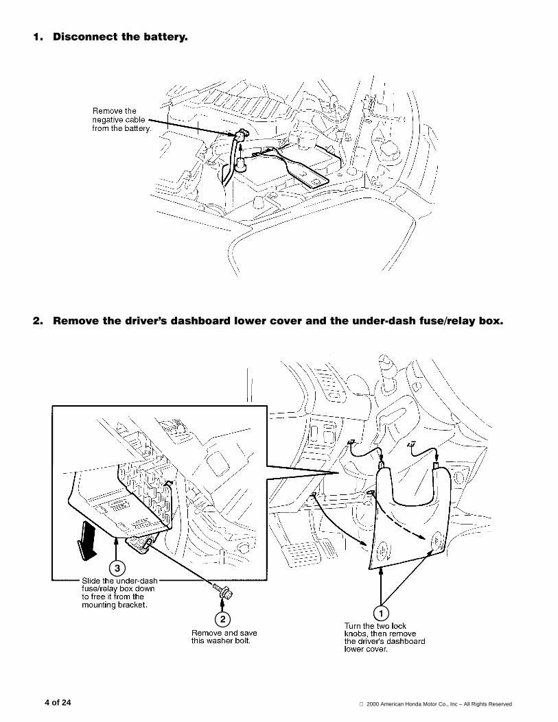
�� ����������� ����
�� ������������������� ���������������������������������������� ���
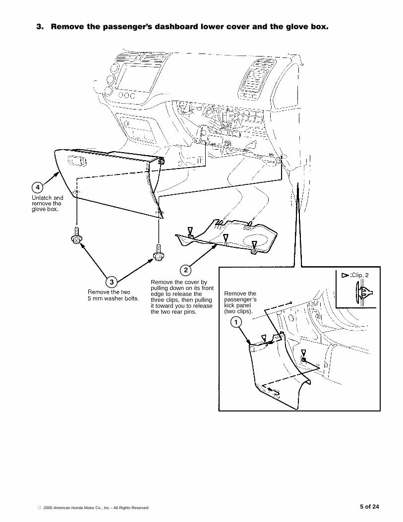
2000 American Honda Motor Co., Inc – All Rights Reserved 5 of 24
�� ������������ �������� ��������������������� ���� ���
Remove the cover bypulling down on its frontedge to release thethree clips, then pullingit toward you to releasethe two rear pins.
Remove thepassenger’skick panel(two clips).
2000 American Honda Motor Co., Inc – All Rights Reserved6 of 24
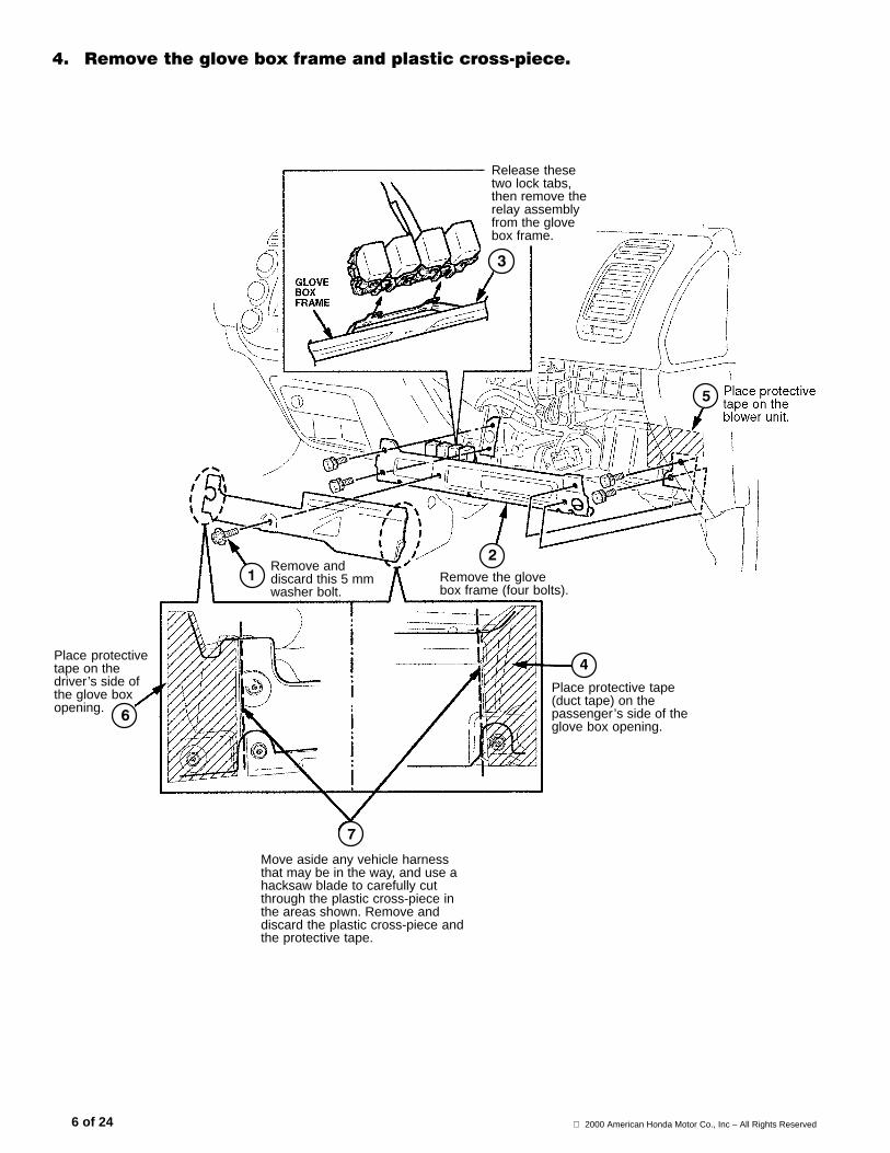
!� ������� ���� �����������������������������
Remove anddiscard this 5 mmwasher bolt.
Remove the glovebox frame (four bolts).
Place protective tape(duct tape) on thepassenger’s side of theglove box opening.
Move aside any vehicle harnessthat may be in the way, and use ahacksaw blade to carefully cutthrough the plastic cross-piece inthe areas shown. Remove anddiscard the plastic cross-piece andthe protective tape.
Place protectivetape on thedriver’s side ofthe glove boxopening.
Release thesetwo lock tabs,then remove therelay assemblyfrom the glovebox frame.
2000 American Honda Motor Co., Inc – All Rights Reserved 7 of 24
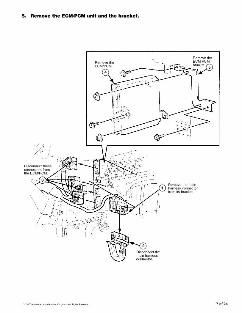
"� �������#$%�&$%����������� ���'�
Remove the mainharness connectorfrom its bracket.
Disconnect theseconnectors fromthe ECM/PCM.
Remove theECM/PCM.
2000 American Honda Motor Co., Inc – All Rights Reserved8 of 24
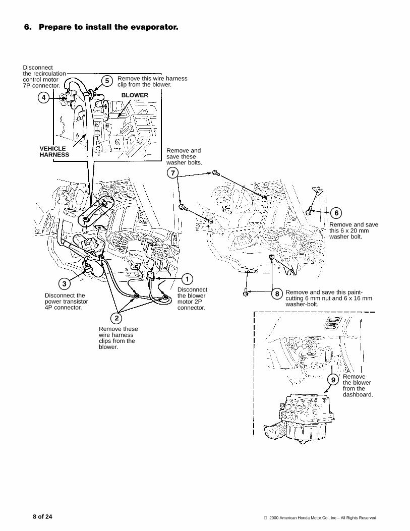
(� &�������������������������
Remove this wire harnessclip from the blower.
Remove andsave thesewasher bolts.
Remove and savethis 6 x 20 mmwasher bolt.
Remove and save this paint-cutting 6 mm nut and 6 x 16 mmwasher-bolt.
BLOWER
VEHICLEHARNESS
Disconnectthe recirculationcontrol motor7P connector.
Remove thesewire harnessclips from theblower.
Disconnectthe blowermotor 2Pconnector.
Disconnect thepower transistor4P connector.
Removethe blowerfrom thedashboard.
2000 American Honda Motor Co., Inc – All Rights Reserved 9 of 24
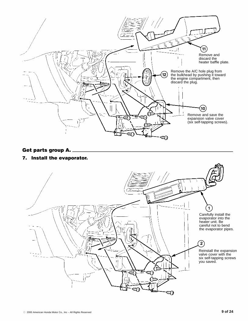
Remove and discard theheater baffle plate.
Remove the A/C hole plug fromthe bulkhead by pushing it towardthe engine compartment, thendiscard the plug.
Remove and save theexpansion valve cover(six self-tapping screws).
)������ �����*��
+� ,�����������������
Reinstall the expansionvalve cover with thesix self-tapping screwsyou saved.
Carefully install theevaporator into theheater unit. Becareful not to bendthe evaporator pipes.
2000 American Honda Motor Co., Inc – All Rights Reserved10 of 24
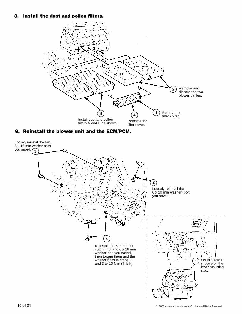
-� ,����������������������������
Install dust and pollenfilters A and B as shown.
Remove anddiscard the twoblower baffles.
Remove thefilter cover.
Reinstall thefilter cover.
.� ���������� ���������������#$%�&$%�
Set the blowerin place on thelower mountingstud.
Loosely reinstall the two6 x 16 mm washer-boltsyou saved.
Reinstall the 6 mm paint-cutting nut and 6 x 16 mmwasher-bolt you saved,then torque them and thewasher bolts in steps 2and 3 to 10 N.m (7 lb-ft).
Loosely reinstall the6 x 20 mm washer- boltyou saved.
2000 American Honda Motor Co., Inc – All Rights Reserved 11 of 24
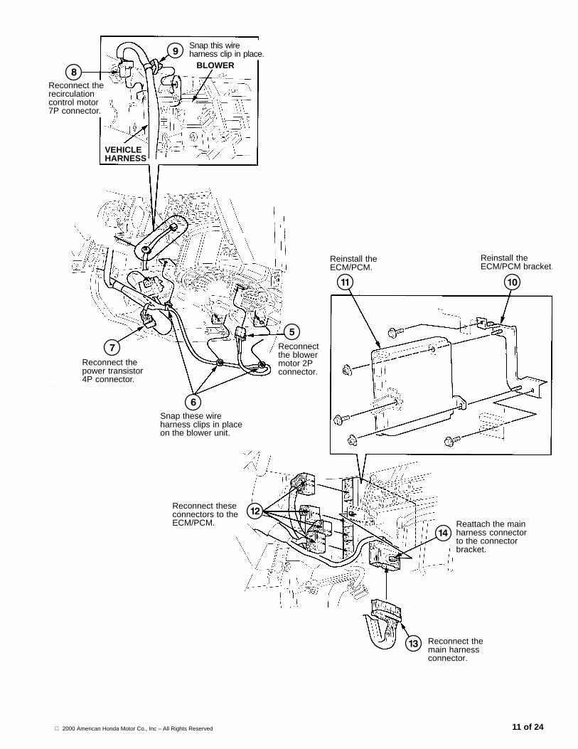
Snap these wireharness clips in placeon the blower unit.
Reconnect thepower transistor4P connector.
Reconnectthe blowermotor 2Pconnector.
Reconnect therecirculation control motor7P connector.
Snap this wireharness clip in place.
BLOWER
VEHICLEHARNESS
Reattach the mainharness connectorto the connectorbracket.
Reconnect themain harnessconnector.
Reconnect theseconnectors to theECM/PCM.
Reinstall theECM/PCM bracket.
Reinstall theECM/PCM.
‘‘‘‘
2000 American Honda Motor Co., Inc – All Rights Reserved12 of 24
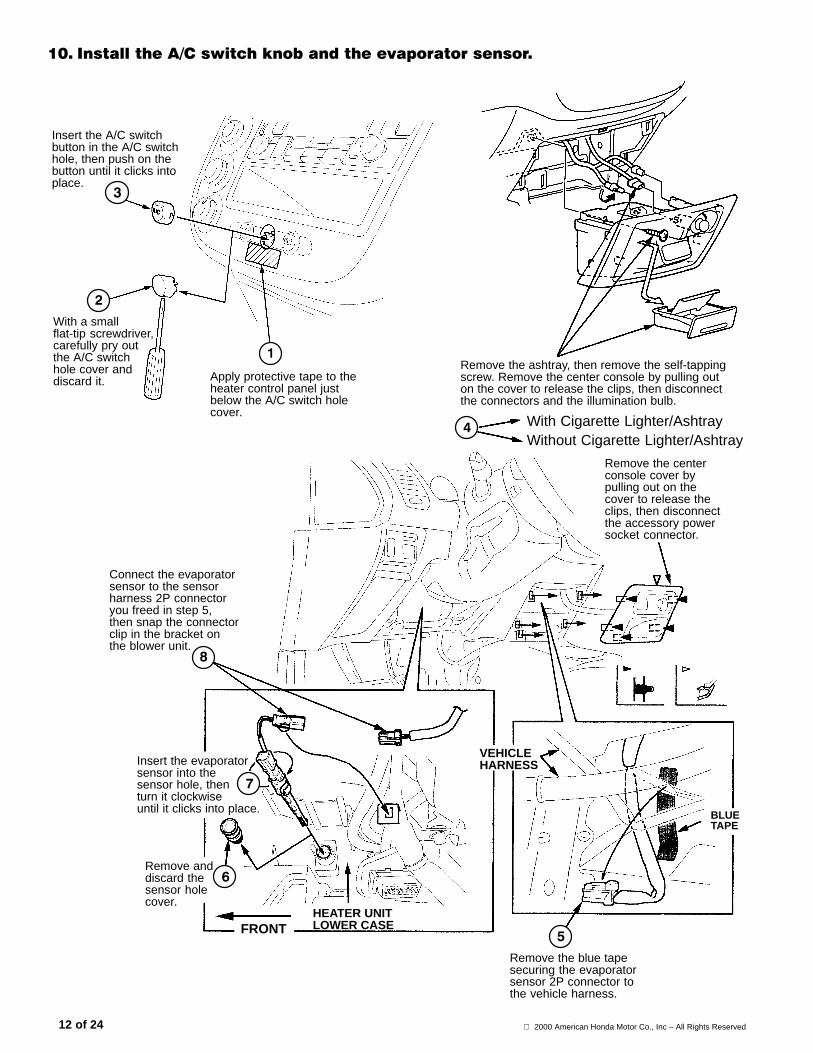
�/� ,��������*�$�������'�� ����������������������
Connect the evaporatorsensor to the sensorharness 2P connectoryou freed in step 5,then snap the connectorclip in the bracket onthe blower unit.
Insert the evaporatorsensor into thesensor hole, thenturn it clockwiseuntil it clicks into place.
Remove anddiscard thesensor holecover.
Remove the blue tapesecuring the evaporatorsensor 2P connector tothe vehicle harness.
HEATER UNITLOWER CASE
VEHICLEHARNESS
Apply protective tape to theheater control panel justbelow the A/C switch holecover.
Insert the A/C switchbutton in the A/C switchhole, then push on thebutton until it clicks intoplace.
FRONT
BLUETAPE
With a smallflat-tip screwdriver,carefully pry outthe A/C switchhole cover anddiscard it.
Remove the ashtray, then remove the self-tappingscrew. Remove the center console by pulling outon the cover to release the clips, then disconnectthe connectors and the illumination bulb.
With Cigarette Lighter/AshtrayWithout Cigarette Lighter/Ashtray
Remove the centerconsole cover bypulling out on thecover to release theclips, then disconnectthe accessory powersocket connector.
2000 American Honda Motor Co., Inc – All Rights Reserved 13 of 24
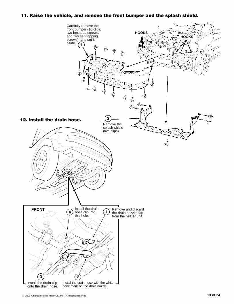
��� ������������0����������������� ������������������������
Carefully remove thefront bumper (10 clips,two hexhead screws,and two self-tappingscrews), and set itaside.
FRONT Remove and discardthe drain nozzle capfrom the heater unit.
Install the drain cliponto the drain hose.
Install the drainhose clip intothis hole.
HOOKSHOOKS
Remove thesplash shield(five clips).
��� ,������������������
Install the drain hose with the whitepaint mark on the drain nozzle.
2000 American Honda Motor Co., Inc – All Rights Reserved14 of 24
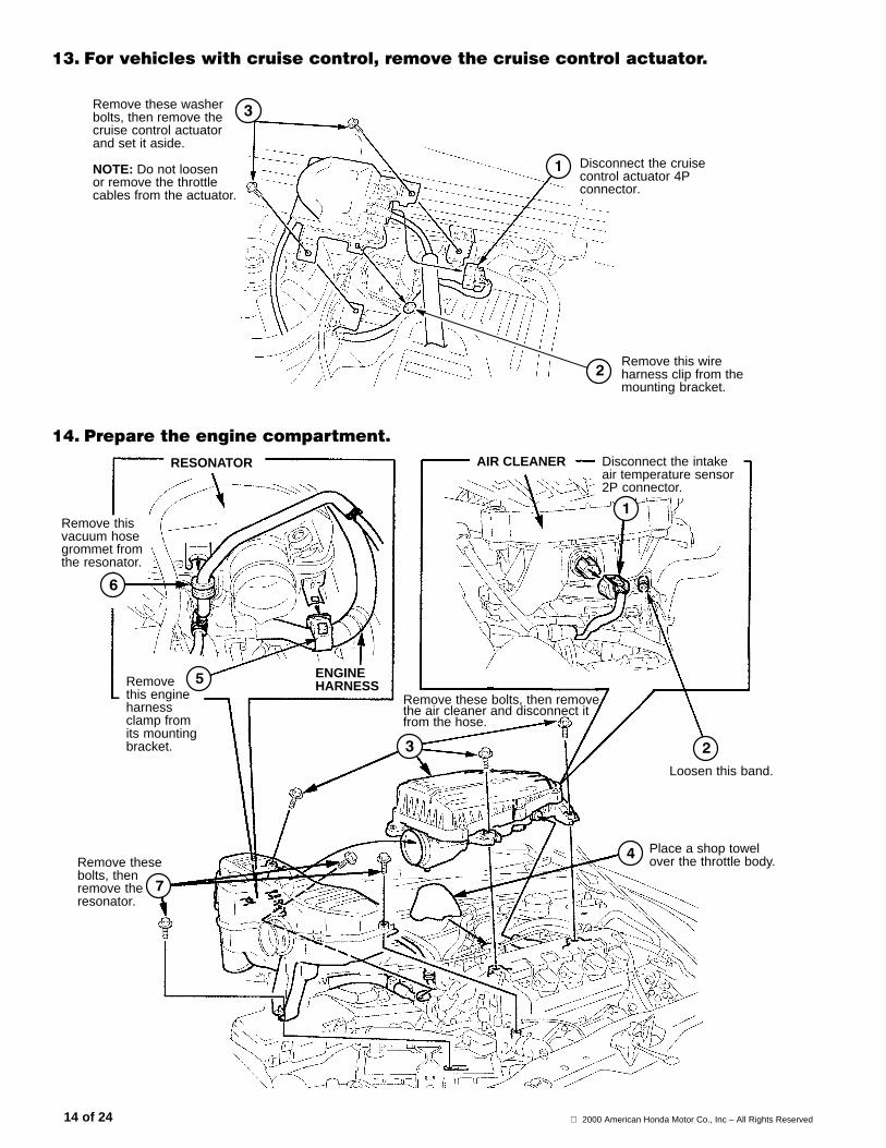
��� 1��������������������������0����������������������������
Remove this wireharness clip from themounting bracket.
Remove these washerbolts, then remove thecruise control actuatorand set it aside.
NOTE: Do not loosenor remove the throttlecables from the actuator.
Disconnect the cruisecontrol actuator 4Pconnector.
�!� &�������� ������������
Remove thesebolts, thenremove theresonator.
Remove these bolts, then removethe air cleaner and disconnect itfrom the hose.
Remove thisvacuum hosegrommet fromthe resonator.
Place a shop towelover the throttle body.
Loosen this band.
ENGINEHARNESS
AIR CLEANERRESONATOR
Removethis engineharnessclamp fromits mountingbracket.
Disconnect the intakeair temperature sensor2P connector.
2000 American Honda Motor Co., Inc – All Rights Reserved 15 of 24
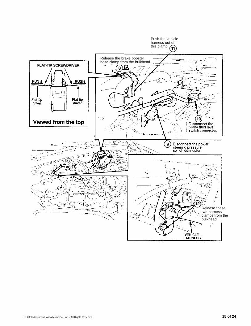
Push the vehicleharness out ofthis clamp.
Release the brake boosterhose clamp from the bulkhead.
Release thesetwo harnessclamps from thebulkhead.
FLAT-TIP SCREWDRIVER
2000 American Honda Motor Co., Inc – All Rights Reserved16 of 24
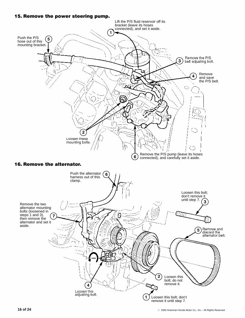
�"� ���������������� ������
Remove the P/S pump (leave its hosesconnected), and carefully set it aside.
Push the P/Shose out of thismounting bracket.
Lift the P/S fluid reservoir off itsbracket (leave its hosesconnected), and set it aside.
Removeand savethe P/S belt.
�(� ���������������
Push the alternatorharness out of thisclamp.
Loosen this bolt; don’tremove it until step 7.
Loosen thisbolt; do notremove it.
Remove the twoalternator mountingbolts (loosened insteps 1 and 3),then remove thealternator and set itaside.
Loosen this bolt;don’t remove ituntil step 7.
2000 American Honda Motor Co., Inc – All Rights Reserved 17 of 24
)������ �����2��
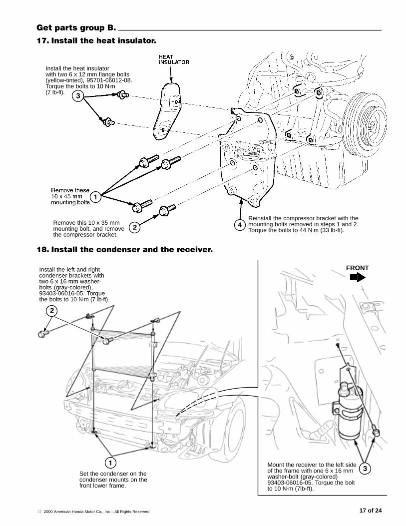
�+� ,��������������������
Reinstall the compressor bracket with themounting bolts removed in steps 1 and 2.Torque the bolts to 44 N.m (33 lb-ft).
Remove this 10 x 35 mmmounting bolt, and removethe compressor bracket.
Install the heat insulatorwith two 6 x 12 mm flange bolts(yellow-tinted), 95701-06012-08.Torque the bolts to 10 N.m(7 lb-ft).
�-� ,����������������������������
Set the condenser on thecondenser mounts on thefront lower frame.
Install the left and rightcondenser brackets withtwo 6 x 16 mm washer-bolts (gray-colored),93403-06016-05. Torquethe bolts to 10 N.m (7 lb-ft).
FRONT
Mount the receiver to the left sideof the frame with one 6 x 16 mmwasher-bolt (gray-colored)93403-06016-05. Torque the boltto 10 N.m (7lb-ft).

2000 American Honda Motor Co., Inc – All Rights Reserved18 of 24
�.� ,�������������������������������
Apply refrigerantoil to both fittings onthe condenser line,then install the linebetween the receiverand condenser.
Secure the condenser line tothe receiver with one 6 x 25mm flange bolt (yellow-tinted),95701-06025-08. Torque thebolt to 10 N.m (7 lb-ft).
Apply refrigerant oilto its fitting, thenconnect the receiverline to the receiverwith one 6 x 25 mmflange bolt(yellow-tinted),95701-06025-08.Torque the bolt to10 N.m (7 lb-ft).
Install receiverline clip B(80387-SM4-A01)into this squarehole.
Install receiver line clipA (80381-S5A-A01) intothis square hole.
Secure the condenserline to the condenserwith one 6 x 25 mmflange bolt (yellow-tinted),95701-06025-08. Torquethe bolt to 10 N.m (7 lb-ft).
Install the compressor on thecompressor bracket with thefour 8 x 100 mm flange bolts(90023-P2A-000). Torquethe bolts to 24 N.m (17lb-ft).
Secure thecondenser fanassembly with two6 x 16 mm washer-bolts (gray-colored),93403-06016-05.Torque the bolts to10 N.m (7 lb-ft).
�/� ,������������������������������������
FRONT
Carefully set thecondenser fanassembly in placeon the condenserfan mounts.
2000 American Honda Motor Co., Inc – All Rights Reserved 19 of 24
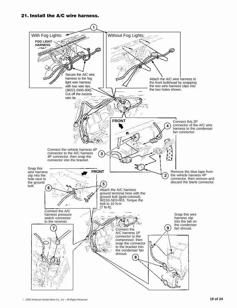
��� ,��������*�$������������
With Fog Lights: Without Fog Lights:
FRONT
Remove the blue tape fromthe vehicle harness 4Pconnector, then remove anddiscard the blank connector.
FOG LIGHTHARNESS
Connect this 2Pconnector of the A/C wireharness to the condenserfan connector.
Snap this wireharness clipinto the tab onthe condenserfan shroud.
Snap thiswire harnessclip into thehole next tothe groundbolt.
Attach the A/C harnessground terminal here with theground bolt (gold-colored),90153-SE0-003. Torque thebolt to 10 N.m(7 lb-ft).
FRONT
Connect the A/Charness pressureswitch connectorto the receiver.
Connect the vehicle harness 4Pconnector to the A/C harness4P connector, then snap theconnector into the bracket.
Connect theA/C harness 1Pconnector to thecompressor, thensnap the connectorto the bracket intothe condenser fanshroud.
Secure the A/C wireharness to the foglight wire harnesswith two wire ties(38221-SW5-300).Cut off the excesswire tie.
Attach the A/C wire harness tothe front bulkhead by snappingthe two wire harness clips intothe two holes shown.
2000 American Honda Motor Co., Inc – All Rights Reserved20 of 24
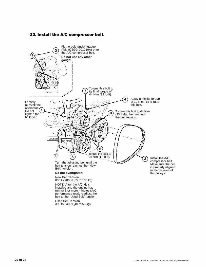
Install the A/Ccompressor belt.Make sure the beltis properly alignedin the grooves ofthe pulleys.
��� ,��������*�$����������� ��
Turn the adjusting bolt until thebelt tension reaches the “NewBelt” tension.Do not overtighten!New Belt Tension:830 to 980 N (85 to 100 kg)NOTE: After the A/C kit isinstalled and the engine hasrun for 5 or more minutes (A/Cperformance test), readjust thebelt to the “Used Belt” tension.Used Belt Tension:390 to 540 N (40 to 55 kg)
Torque this bolt toits final torque of44 N.m (33 lb-ft).
Fit the belt tension gauge(T/N 07JGG-001010A) ontothe A/C compressor belt.Do not use any othergauge!
TightenLoosen
Looselyreinstall thealternator.Do nottighten thebolts yet.
Torque this bolt to24 N.m (17 lb-ft).
Torque this bolt to 44 N.m(33 lb-ft), then recheckthe belt tension.
Apply an initial torqueof 19 N.m (14 lb-ft) tothis bolt.
2000 American Honda Motor Co., Inc – All Rights Reserved 21 of 24
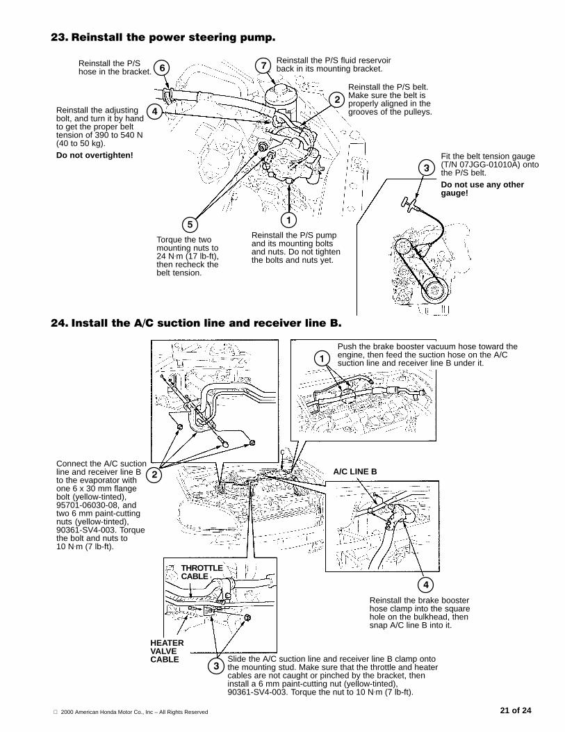
��� ������������������� ������
Reinstall the adjustingbolt, and turn it by handto get the proper belttension of 390 to 540 N(40 to 50 kg).Do not overtighten!
Reinstall the P/Shose in the bracket.
Fit the belt tension gauge(T/N 07JGG-01010A) ontothe P/S belt.Do not use any othergauge!
Torque the twomounting nuts to24 N.m (17 lb-ft),then recheck thebelt tension.
Reinstall the P/S pumpand its mounting boltsand nuts. Do not tightenthe bolts and nuts yet.
Reinstall the P/S belt.Make sure the belt isproperly aligned in thegrooves of the pulleys.
Reinstall the P/S fluid reservoirback in its mounting bracket.
�!� ,��������*�$��������������������������2�
Slide the A/C suction line and receiver line B clamp ontothe mounting stud. Make sure that the throttle and heatercables are not caught or pinched by the bracket, theninstall a 6 mm paint-cutting nut (yellow-tinted),90361-SV4-003. Torque the nut to 10 N.m (7 lb-ft).
Reinstall the brake boosterhose clamp into the squarehole on the bulkhead, thensnap A/C line B into it.
Connect the A/C suctionline and receiver line Bto the evaporator withone 6 x 30 mm flangebolt (yellow-tinted),95701-06030-08, andtwo 6 mm paint-cuttingnuts (yellow-tinted),90361-SV4-003. Torquethe bolt and nuts to10 N.m (7 lb-ft).
Push the brake booster vacuum hose toward theengine, then feed the suction hose on the A/Csuction line and receiver line B under it.
HEATERVALVECABLE
A/C LINE B
THROTTLECABLE
2000 American Honda Motor Co., Inc – All Rights Reserved22 of 24
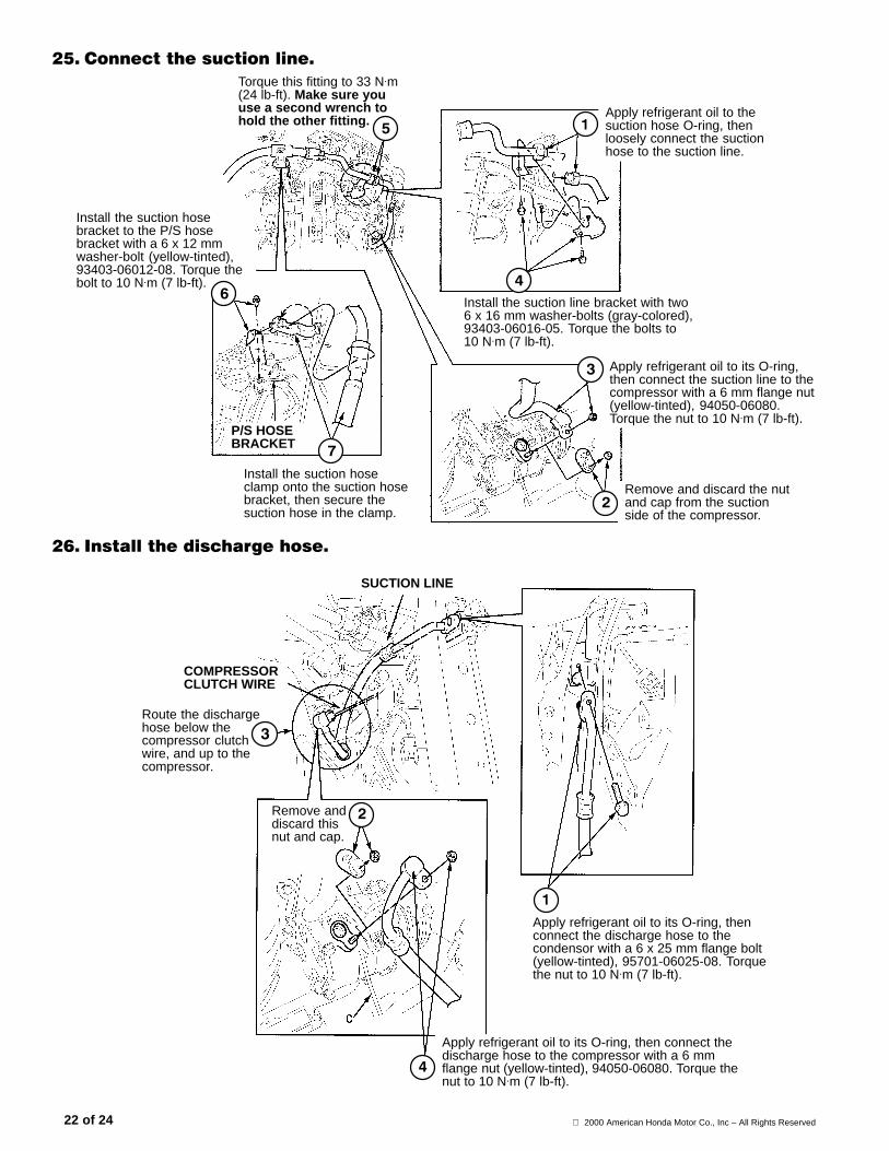
�"� $������������������
Install the suction hosebracket to the P/S hosebracket with a 6 x 12 mmwasher-bolt (yellow-tinted),93403-06012-08. Torque thebolt to 10 N.m (7 lb-ft).
Remove and discard the nutand cap from the suctionside of the compressor.
Apply refrigerant oil to thesuction hose O-ring, thenloosely connect the suctionhose to the suction line.
Install the suction line bracket with two6 x 16 mm washer-bolts (gray-colored),93403-06016-05. Torque the bolts to10 N.m (7 lb-ft).
Apply refrigerant oil to its O-ring,then connect the suction line to thecompressor with a 6 mm flange nut(yellow-tinted), 94050-06080.Torque the nut to 10 N.m (7 lb-ft).
Torque this fitting to 33 N.m(24 lb-ft). Make sure youuse a second wrench tohold the other fitting.
Install the suction hoseclamp onto the suction hosebracket, then secure thesuction hose in the clamp.
P/S HOSEBRACKET
�(� ,��������������� �����
Route the dischargehose below thecompressor clutchwire, and up to thecompressor.
SUCTION PIPESUCTION LINE
Apply refrigerant oil to its O-ring, thenconnect the discharge hose to thecondensor with a 6 x 25 mm flange bolt(yellow-tinted), 95701-06025-08. Torquethe nut to 10 N.m (7 lb-ft).
Apply refrigerant oil to its O-ring, then connect thedischarge hose to the compressor with a 6 mmflange nut (yellow-tinted), 94050-06080. Torque thenut to 10 N.m (7 lb-ft).
Remove anddiscard thisnut and cap.
COMPRESSORCLUTCH WIRE
2000 American Honda Motor Co., Inc – All Rights Reserved 23 of 24
)������ �����$��
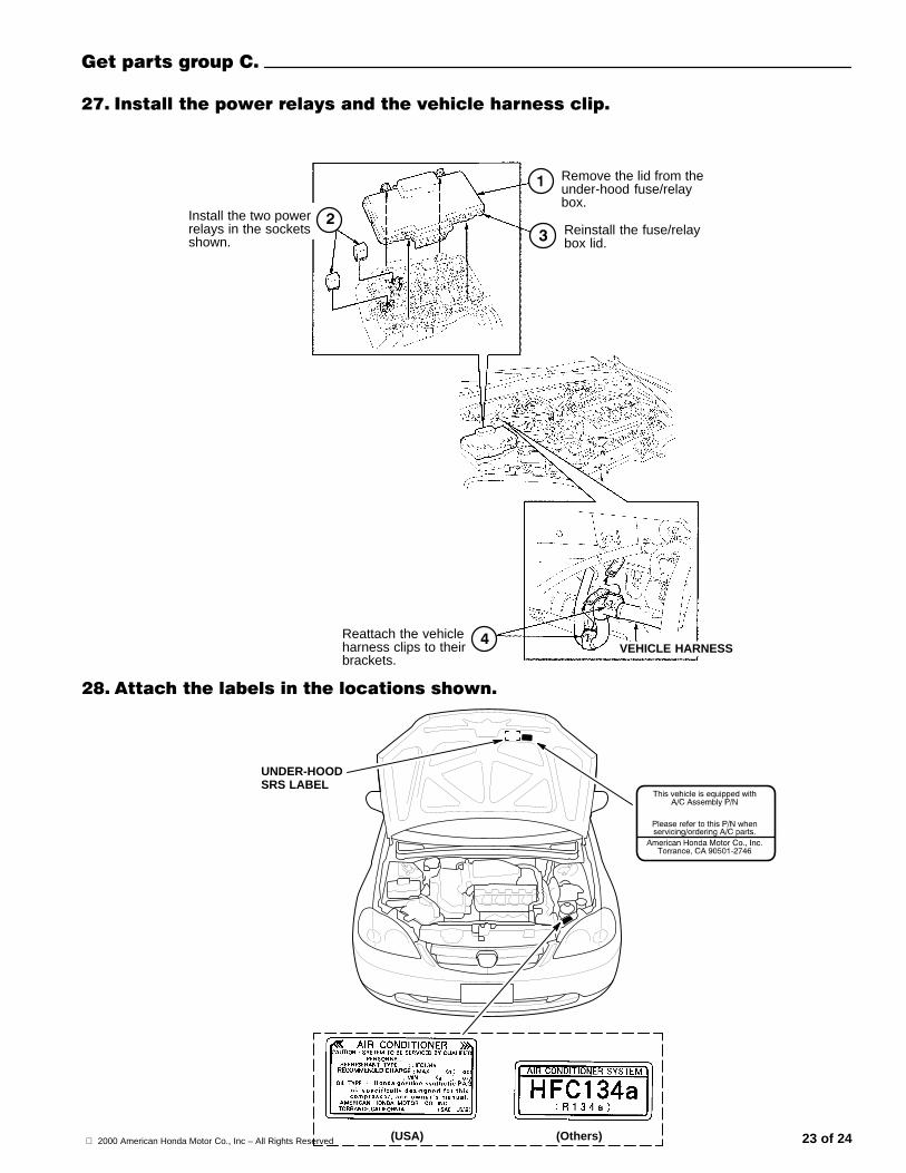
�+� ,�������������������������������������������
Install the two powerrelays in the socketsshown.
UNDER-HOODSRS LABEL
(USA) (Others)
�-� *�������� �����������������������
Remove the lid from theunder-hood fuse/relaybox.
Reinstall the fuse/relaybox lid.
Reattach the vehicleharness clips to theirbrackets.
VEHICLE HARNESS
2000 American Honda Motor Co., Inc – All Rights Reserved24 of 24
�.� ����������������� ������
Relay assembly and glove box frame
Glove box
Passenger’s dashboard lower cover
Passenger’s kick panel
Center console cover, and reconnect theaccessory power socket or cigarette lighter.
Under-dash fuse/relay box
Driver’s dashboard lower cover
Front bumper and splash shield
Cruise control actuator; tighten the mounting bolts to 10 N⋅m (7 lb-ft).
Power steering pressure switch connector
Brake fluid level switch connector
Resonator and air cleaner case
Reconnect the negative cable to thebattery.
Check for battery voltage at the accessorypower socket (or cigarette lighter).
�/� ��������������� ���������
Whenever the battery or the ECM/PCM isdisconnected, the ECM/PCM must relearn theproper idle air control (IAC) values. To do this,follow this procedure exactly.
–1 Start the engine, and turn off allaccessories (A/C, radio, defogger, etc.).
–2 Warm the engine up to normal operatingtemperatures (cooling fans come ontwice), then let the engine idle for 10minutes.
If the above procedure is not done correctly,the engine will have an erratic idle.
��� #�������������
The HFC-134a and compressor oil used inthis A/C system are highly moistureabsorbent. After installing the system, makesure you evacuate it for at least 15 minutes.
NOTE:
� If low pressure does not reach more than700 mm Hg (27 in-Hg) in 15 minutes, thereis probably a leak in the system. Partiallycharge the system, and check for leaks(see step 32).
� If the system is left open, the desiccant in thereceiver tank will become saturated withmoisture, requiring longer evacuation time.
��� $��� ��������
� This system requires only the amount ofHFC-134a refrigerant shown below. If youovercharge the system, the engine and theA/C will malfunction. Do not overcharge!Select the appropriate units of measure foryour refrigerant charging station.
500 to 550 grams
0.50 to 0.55 kilograms
1.1 to 1.2 pounds
17.6 to 19.4 ounces
� Do not add oil to the compressor; a newcompressor already contains enough oil forthe entire A/C system. If you are replacingcompressor oil that has leaked out of thesystem, use only Sanden SP-10 oil.
� Using the wrong oil, or mixing different typesof oil, will result in abnormal compressor noiseor seizure, or shortened compressor servicelife. These conditions are not covered by thewarranty policy.
��� $��'�������'��
When testing for leaks, follow theseguidelines:� Make sure you use a leak detector
designed for A/C systems that useHFC-134a.
� To avoid false readings, do not use a testerdesigned to detect Freon (CFC-12).
� Because HFC-134a is heavier than air,always check 360° around all fittings.
� If you lose or damage an O-ring during A/Cinstallation, make sure you order the correctreplacement as listed here:
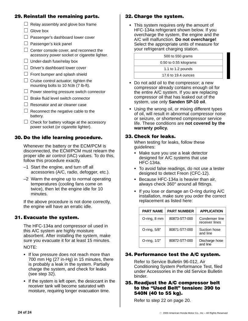
PART NAME PART NUMBER APPLICATION
O-ring, 8 mm 80873-ST7-000 Condenser linereceiver lines
O-ring, 5/8″ 80871-ST7-000 Suction hoseand line
O-ring, 1/2″ 80872-ST7-000 Discharge hoseand line
�!� &�������������*�$������
Refer to Service Bulletin 96-012, AirConditioning System Performance Test, filedunder Accessories in the old Service Bulletinbinder.
�"� ���3�����*�$����������� �����45���2�6������7��./��"!/8�9!/���""�' :�
Refer to step 22 on page 20.