Embed Size (px)
Citation preview

© 2004 American Honda Motor Co., Inc. - All Rights Reserved. AII 27855 (0411) 1 of 24
Accessory Application Publications No.
Issue Date
NOV 2004
2005 CIVIC2- AND 4-DOOR
AIR CONDITIONER2-DOOR HX4-DOOR DX
INSTALLATIONINSTRUCTIONS
AII 27855
What’s New
The installation instructions for the 2005 Civic A/C arethe same as for the 2004 model.
A/C Kit:P/N 80000-S5D-A24 for U.S.P/N 80000-S5D-C24 for Canada
TOOLS AND SUPPLIES REQUIRED
Duct tape
INSTALLATION
Customer Information: The information in theseinstallation instructions is intended for use only byskilled technicians who have the proper tools,equipment, and training to correctly and safely addequipment to your vehicle. These procedures shouldnot be attempted by “do-it-yourselfers.”
NOTE:
• Make sure you have the anti-theft code for theaudio system.
• Write down the customer’s radio stationpresets. The radio memory will be erased whenyou disconnect the battery.
• Make sure you install the right part. Use theillustrations on pages 2 and 3 as a guide to checkthe parts before you install them.
• Don’t remove plugs and caps from fittings untilthe parts are ready to connect. This will keep outmoisture and dirt, which could cause wear anddamage.
Hacksaw bladeTrim clip removerOpen-end wrench setScrewdriversSocket wrench setTorque wrenchTension gaugeRefrigerant oil (R-12 mineral oil or R-134a PAG oil)Fender, floor, and seat coversHFC-134a refrigerant recovery/recycling/charging
stationGlovesEye protection (face shield or safety goggles)Electronic leak detector
NOTICE
NOTICE
During Installation:
• Before you connect any line or hose, check andlube its O-ring. Make sure the O-ring is on thefitting, put a few drops of refrigerant oil on theO-ring, then connect the fitting.
• You may use either type of refrigerant oil to lubricateO-rings and fittings.
• If you add or replace refrigerant oil in the system,use only this PAG oil: Sanden SP-10,P/N 38897-P13-A01.
• Route and secure the lines and hoses properly.Maintain clearance between them and surroundingparts.
• Use two wrenches to tighten or loosen fittings.Hold one fitting in place while you tighten the otherone against it.
Don’t overtighten; you could damagethe fittings. Before you tighten a fitting, check thetorque listed for it. If leaks are caused by faultyO-rings, overtightening the fitting won’t help.
• Before you connect each electrical connector,check its terminals. Make sure the terminals aren’tbent or out of place.
• Use only HFC-134a in this system. Do not useCFC 12 (Freon); do not install parts designed for usein a CFC system.
• Use a charging station. A/C charging stations adrefrigerant recovery/recycling stations minimize therelease of CFCs and HFCs to the atmosphere. Usethem for all A/C charging and service work accordingto the manufacturers' instructions.
• Do not overcharge. This system requires only theamount of HFC-134a refrigerant shown below. If youovercharge the system, the engine and the A/C willmalfunction.
500 to 550 grams
0.50 to 0.55 kilograms
1.1 to 1.2 pounds
17.6 to 19.4 ounces

Group A
Group C
Group Part P/N Qty
Drain hose clip 53747-SA5-003 1A/C button 79601-S5A-003 1Evaporator 80210-S5D-G03 1Drain hose 80271-S5A-000 1Dust and pollen filter A 80290-S5D-A01 1Dust and pollen filter B 80295-S5D-A01 1Evaporator sensor 80560-S5A-941 1
Wire ties 38221-SW5-300 2Condenser fan assembly 38605-PMM-A12 1Compressor 38800-PLM-A12 1Compressor belt 38920-PLR-004 1Heat insulator 38935-PLM-A00 1Condenser assembly 80100-S5A-T01 1Right condenser bracket 80107-S5A-000 1Left condenser bracket 80108-S5A-000 1Suction line 80311-S5D-A12 1Discharge hose 80315-S5A-013 1A/C suction line and receiver line B 80320-S5D-A12 1Condenser line 80331-S5D-A11 1Receiver line 80341-S5D-A02 1Receiver 80350-S5D-A01 1Suction hose clamp A 80360-S5A-A00 1Suction hose bracket 80361-S5A-A00 1Suction line bracket 80363-S5A-A01 1Receiver line clip A 80381-S5A-A01 1Receiver line clip B 91548-S5A-003 1A/C wire harness 80460-S5A-A00 1Flange bolts, 8 x 100 mm 90023-P2A-000 4Ground bolt, 6 x 12 mm (brass-colored) 90153-SE0-003 1Paint cutting nut, 6 mm (yellow-tinted) 90361-SV4-003 3Washer-bolt, 6 x 12 mm (yellow-tinted) 93403-06012-08 1Washer-bolts, 6 x 16 mm (gray-colored) 93403-06016-05 7Flange bolts, 6 x 12 mm (yellow-tinted) 95701-06012-08 2Flange bolts, 6 x 25 mm (yellow-tinted) 95701-06025-08 4Flange bolt, 6 x 30 mm (yellow-tinted) 95701-06030-08 1
Power relay (4P) 39794-S0K-A01 2Information label (Canada) 80050-SP0-000 1Information label (USA) 80050-SR3-H00 1A/C kit identification label (USA) 8005X-S5D-A24 1
A
B
C
80290-S5D-A01
80560-S5A-941
79601-S5A-003
80271-S5A-000
80210-S5D-G02
53747-SA5-003
80295-S5D-A01
39794-S0K-A01 8005X-S5D-A21 80050-SR3-H00 80050-SP0-000
80210-SD5-G03
AIR CONDITIONER SYSTEM
8005X-SD5-A24
AII 27855 (0411) © 2004 American Honda Motor Co., Inc. - All Rights Reserved.2 of 24
90023-P2A-000
80350-S5D-A01
80108-S5A-000
93403-06016-05(Gray-colored)
80100-S5A-003
93403-06016-05(Gray-colored)
93403-06016-05(Gray-colored)
08F13-S8410013
38605-PMM-A11
80363-S5A-A01
80107-S5A-00080315-S5A-013
(Yellow-tinted)95701-06025-08 80331-S5D-A11
(Yellow-tinted)95701-06025-08
(Gray-colored)93403-06016-05
93403-06016-05(Gray colored)
80460-S5A-A00
(Brass-colored)90153-SE0-003
80341-S5D-A11(Yellow-tinted)95701-06025-08
80311-S5D-A12
90361-SV4-003(Yellow-tinted)93403-06016-05
(Gray-colored)
80387-SM4-A01
80381-S5A-A01
80361-S5A-A00
80360-S5A-A00(Yellow-tinted)93403-06012-08
80320-S5D-A12(Yellow-tinted)90361-SV4-003
(Yellow-tinted)95701-06030-08
38920-PLR-004
38935-PLM-A00(Yellow tinted)95701-06012-08
38800-PLM-A02
Group B
38800-PLM-A12
80341-S5D-A02
91548-S5A-003
38605-PMM-A12
80100-S5A-T01
38221-SW5-300
© 2004 American Honda Motor Co., Inc. - All Rights Reserved. AII 27855 (0411) 3 of 24
4 of 24 AII 27855 (0411) © 2004 American Honda Motor Co., Inc. - All Rights Reserved.
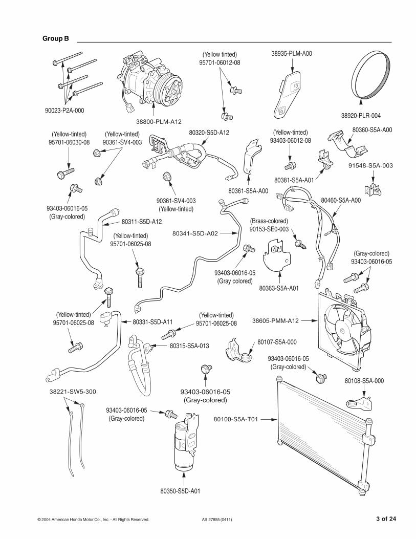
1. Disconnect the battery.
2. Remove the driver’s dashboard lower cover and the under-dash fuse/relay box.
Remove thenegative cablefrom the battery.
Turn the two lockknobs, then removethe driver’s dashboardlower cover.
Remove and savethis washer bolt.
Slide the under-dashfuse/relay box downto free it from themounting bracket.
3
2
1

© 2004 American Honda Motor Co., Inc. - All Rights Reserved. AII 27855 (0411) 5 of 24
3. Remove the passenger’s dashboard lower cover and the glove box.
Remove thepassenger’skick panel(two clips).
Remove the cover bypulling down on its frontedge to release thethree clips, then pullingit toward you to releasethe two rear pins.
Unlatch andremove theglove box.
Remove the two5 mm washer bolts.
: Clip, 22
1
3
4

6 of 24 AII 27855 (0411) © 2004 American Honda Motor Co., Inc. - All Rights Reserved.
4. Remove the glove box frame and plastic cross-piece.
GLOVEBOXFRAME
Remove anddiscard this 5 mmwasher bolt.
Remove the glovebox frame (four bolts).
Placeprotectivetape on theblower unit.
Place protective tape(duct tape) on thepassenger’s side of theglove box opening.
Place protectivetape on thedriver’s side ofthe glove boxopening.
Move aside any vehicle harnessthat may be in the way, and use ahacksaw blade to carefully cutthrough the plastic cross-piece inthe areas shown. Remove anddiscard the plastic cross-piece andthe protective tape.
Release these two lock tabs, then remove therelay assembly from the glove box frame.

© 2004 American Honda Motor Co., Inc. - All Rights Reserved. AII 27855 (0411) 7 of 24
5. Remove the ECM/PCM unit and the bracket.
Remove the mainharness connectorfrom its bracket.
Disconnect theseconnectors fromthe ECM/PCM.
Remove theECM/PCM.
2
1
3
Disconnect themain harnessconnector.
5
Remove theECM/PCMbracket.
4

8 of 24 AII 27855 (0411) © 2004 American Honda Motor Co., Inc. - All Rights Reserved.
6. Prepare to install the evaporator.
Disconnect thepower transistor4P connector.
3
2
1
8
6
7
Remove thesewire harnessclips from theblower.
Disconnectthe blowermotor 2Pconnector.
Remove and savethese washer bolts.
Remove andsave this6 x 20 mmwasher bolt.
Remove and save thispaintcutting 6 mm nut and6 x 16 mm washer-bolt.
9 Removethe blowerfrom thedashboard.
Disconnectthe recirculationcontrol motor7P connector.
VEHICLEHARNESS
Remove this wire harnessclip from the blower.
BLOWER
5
4
Remove and save thispaint-cutting 6 mm nut and6 x 16 mm washer-bolt.

© 2004 American Honda Motor Co., Inc. - All Rights Reserved. AII 27855 (0411) 9 of 24
Get Parts Group A.
7. Install the evaporator.
Remove anddiscard theheater baffle plate.
11
12
10
Remove the A/C hole plug from the bulkhead by pushing it toward the engine compartment, then discard the plug.
Remove and save the expansion valve cover (six self-tapping screws).
Carefully install theevaporator into theheater unit. Becareful not to bend the evaporator pipes.
Reinstall the expansionvalve cover with thesix self-tapping screwsyou saved.
1
2Reinstall the expansionvalve cover with thesix self-tapping screwsyou saved in step 10.

10 of 24 AII 27855 (0411) © 2004 American Honda Motor Co., Inc. - All Rights Reserved.
9. Reinstall the blower unit and the ECM/PCM.
8. Install the dust and pollen filters.
AB
1
2
3 4Install dust and pollenfilters A and B as shown.
Remove and discard the two blower baffles.
Remove the filter cover.
Reinstall the filter cover.
4
2
3Loosely reinstall the two 6 x 16 mm washer-bolts you saved.
Loosely reinstall the6 x 20 mm washer-boltyou saved.
Reinstall the 6 mm paintcuttingnut and 6 x 16 mm washer-bolt you saved,then torque them and the washer bolts in steps 2and 3 to 10 N.m (7 lb-ft).
1 Set the blower in place on the lower mounting stud.
Reinstall the 6 mm paintcutting nut and6 x 16 mm washer-bolt you saved,then torque them and the washer boltsin steps 2 and 3 to 10 N.m (7 lb-ft).

© 2004 American Honda Motor Co., Inc. - All Rights Reserved. AII 27855 (0411) 11 of 24
Reconnectthe blowermotor 2Pconnector.
Reattach the mainharness connectorto the connectorbracket.
Reinstall theECM/PCM.
Reconnect theseconnectors to theECM/PCM.
Reinstall theECM/PCMbracket.
Reconnect thepower transistor4P connector.
Snap these wireharness clips in placeon the blower unit.
Reconnect the mainharnes connector.
7
6
5
11 10
1412
13
Reconnectthe recirculationcontrol motor7P connector.
VEHICLEHARNESS
Snap this wireharness clip in place.
BLOWER
9
8
Reconnect the mainharness connector.

12 of 24 AII 27855 (0411) © 2004 American Honda Motor Co., Inc. - All Rights Reserved.
10. Install the A/C switch knob and the evaporator sensor.
Remove the blue tape securing theevaporator sensor 2P connectorto the vehicle harness.
HEATER UNITLOWER CASE
Insert the A/C switchbutton in the A/C switchhole, then push on thebutton until it clicksinto place.
With a smallflat-tip screwdriver,carefully pry outthe A/C switchhole cover anddiscard it.
FRONT
BLUETAPE
Remove the ashtray, then remove the self-tappingscrew. Remove the center console by pulling outon the cover to release the clips, then disconnectthe connectors and the illumination bulb.
With Cigarette Lighter/AshtrayWithout Cigarette Lighter/Ashtray
Remove the center console cover bypulling out on the cover to releasethe clips, then disconnect theaccessory power socket connector.
7
VEHICLEHARNESS
5
6Remove anddiscard thesensor holecover.
Insert the evaporatorsensor into thesensor hole, thenturn it clockwiseuntil it clicks into place.
Connect the evaporatorsensor to the sensorharness 2P connectoryou freed in step 5,then snap the connectorclip in the bracket onthe blower unit. 8
3
2
Apply protective tape to theheater control panel just belowthe A/C switch hole cover.
1
4

© 2004 American Honda Motor Co., Inc. - All Rights Reserved. AII 27855 (0411) 13 of 24
Remove thesplash shield(five clips).
HOOKS
Carefully remove the front bumper (10 clips,two hexhead screws, and two self-tappingscrews), and set it aside.
2
Install the drain hose with the whitepaint mark on the drain nozzle.
Install the drain hoseclip into this hole
FRONT
Install the drain cliponto the drain hose.
1
2
1
4
3
Remove and discardthe drain nozzle capfrom the heater unit.
HOOKS
11. Raise the vehicle, and remove the front bumper and the splash shield.
12. Install the drain hose.

14 of 24 AII 27855 (0411) © 2004 American Honda Motor Co., Inc. - All Rights Reserved.
13. For vehicles with cruise control, remove the cruise control actuator.
14. Prepare the engine compartment.
1
2
3Disconnect the cruisecontrol actuator 4Pconnector.
Remove this wireharness clip from themounting bracket.
Remove these washerbolts, then remove thecruise control actuatorand set it aside.
NOTE: Do not loosenor remove the throttlecables from the actuator.
ENGINEHARNESS
RESONATOR
6
5
3
7
4
2
1
Remove thisvacuum hosegrommet fromthe resonator.
Remove this engine harnessclamp from its mounting bracket.
AIR CLEANERDisconnect the intake air temperature sensor 2P connector.
Loosenthis band.
Remove these bolts, then remove the air cleaner and disconnect it from the hose.
Remove these bolts,then remove theresonator.
Place a shop towelover the throttle body.

© 2004 American Honda Motor Co., Inc. - All Rights Reserved. AII 27855 (0411) 15 of 24
PUSH PUSH
FLAT-TIP SCREWDRIVER
Top View
Release the brake boosterhose clamp from the bulkhead.
Push the vehicleharness out ofthis clamp.
Disconnect thebrake fluid levelswitch connector.
Disconnect the power steeringpressure switch connector.
9
Release thesetwo harnessclamps from thebulkhead.
VEHICLE HARNESS
11
10
12
8

16 of 24 AII 27855 (0411) © 2004 American Honda Motor Co., Inc. - All Rights Reserved.
15. Remove the power steering pump.
16. Remove the alternator.
Remove the P/S pump (leave its hosesconnected), and carefully set it aside.
Push the P/S hose out of this mounting bracket.
Lift the P/S fluid reservoir off its bracket (leave its hoses connected), and set it aside.
Removeand savethe P/S belt.
Loosen thesemounting bolts.
Remove the P/Sbelt adjusting bolt.
1
2
5
3
4
6
Loosen thisadjusting bolt.
6
5
3
Push the alternatorharness out of this clamp.
Loosen this bolt; don’t remove it until step 7.
Loosen this bolt; do not remove it.
Remove the twoalternator mountingbolts (loosened insteps 1 and 3),then remove thealternator andset it aside.
Loosen this bolt;don’t removeit until step 7.
Remove anddiscard thealternator belt.
1
2
4
7

© 2004 American Honda Motor Co., Inc. - All Rights Reserved. AII 27855 (0411) 17 of 24
Get Parts Group B.
17. Install the heat insulator.
18. Install the condenser and the receiver.
Reinstall this 10 x 35 mmmounting bolt in this hole.Torque the bolts to 44 N.m (33 lb-ft).
Remove this 10 x 35 mmmounting bolt, and removethe compressor bracket.
Reinstall the compressorbracket with the mountingbolts removed in step 1.Torque the bolts to 44 N.m(33 lb-ft).
Install the heat insulator with two 6 x 12 mm flange bolts (yellow-tinted), 95701-06012-08.Torque the bolts to 10 N.m (7 lb-ft).
Remove these10 x 45 mmmounting bolts.
1 4
3
52
HEATINSULATOR
Set the condenser on thecondenser mounts on thefront lower frame.
FRONTInstall the left and right condenser brackets withtwo 6 x 16 mm washer-bolts (gray-colored),93403-06016-05. Torque the bolts to 10 N.m (7 lb-ft).
1
2
3Mount the receiver to the left side of the frame with one 6 x 16 mm washer-bolt (gray-colored), 93403-06016-05. Torque the bolt to 10 N.m (7lb-ft).
Mount the receiver to the left side of the frame with one6 x 16 mm washer-bolt (gray-colored), 93403-06016-05.Torque the bolt to 10 N.m (7lb-ft).
Install the heat insulator with two 6 x 12 mmflange bolts (yellow-tinted), 95701-06012-08.Torque the bolts to 10 N.m (7 lb-ft).
Install the left and right condenser brackets withtwo 6 x 16 mm washer-bolts (gray-colored),93403-06016-05. Torque the bolts to 10 N.m (7 lb-ft).
Reinstall this 10 x 35 mmmounting bolt in this hole.Torque the bolts to 44 N.m (33 lb-ft).
Reinstall the compressorbracket with the mountingbolts removed in step 1.Torque the bolts to 44 N.m(33 lb-ft).

18 of 24 AII 27855 (0411) © 2004 American Honda Motor Co., Inc. - All Rights Reserved.
19. Install the condenser and receiver lines.
20. Install the compressor and the condenser fan.
FRONT
3
6
1
24
Secure the condenser line tothe receiver with one 6 x 25mm flange bolt (yellow-tinted),95701-06025-08. Torque thebolt to 10 N.m (7 lb-ft).
Apply refrigerantoil to both fittings onthe condenser line,then install the linebetween the receiverand condenser.
Secure the condenserline to the condenserwith one 6 x 25 mmflange bolt (yellow-tinted),95701-06025-08. Torquethe bolt to 10 N.m (7 lb-ft).
Apply refrigerant oilto its fitting, thenconnect the receiverline to the receiverwith one 6 x 25 mmflange bolt(yellow-tinted),95701-06025-08.Torque the bolt to10 N.m (7 lb-ft).
Install receiver line clip A(80381-S5A-A01) intothis square hole.
Install receiverline clip B(80387-SM4-A01)into this squarehole.
5
Carefully set the condenser fan assembly in place on the condenser fan mounts.
Install the compressor on the compressor bracket with the four 8 x 100 mm flange bolts (90023-P2A-000). Torque the bolts to 24 N.m (17lb-ft).
Secure the condenser fanassembly with two 6 x 16 mm washer-bolts (gray-colored),93403-06016-05. Torque the bolts to 10 N.m (7 lb-ft).
3
2
1
Install receiverline clip B(91548-S5A-003)into this squarehole.
Secure the condenser line tothe receiver with one 6 x 25 mmflange bolt (yellow-tinted),95701-06025-08. Torque the boltto N.m (7 lb-ft).
Secure the condenserline to the condenserwith one 6 x 25 mmflange bolt (yellow-tinted),95701-06025-08. Torquethe bolt to 10 N.m (7 lb-ft).
Apply refrigerant oil to itsfitting, then connect thereceiver line to the receiverwith one 6 x 25 mm flangebolt (yellow-tinted),95701-06025-08. Torquethe bolt to 10 N.m (7 lb-ft).
Install the compressor on the compressorbracket with the four 8 x 100 mm flangebolts (90023-P2A-000). Torque the boltsto 24 N.m (17 lb-ft).
Secure the condenser fanassembly with two 6 x 16 mmwasher-bolts (gray-colored),93403-06016-05. Torque thebolts to 10 N.m (7 lb-ft).

© 2004 American Honda Motor Co., Inc. - All Rights Reserved. AII 27855 (0411) 19 of 24
Snap this wire harness clip into the tab on the condenser fan shroud.
Attach the A/C harnessground terminal here with theground bolt (gold-colored),90153-SE0-003. Torque thebolt to 10 N.m (7 lb-ft).
FRONT
FRONT
With Fog Lights: Without Fog Lights:FOG LIGHTHARNESS
Connect the vehicle harness 4P connector to the A/C harness 4P connector, then snap the connector into the bracket.
Attach thecompressorharness clip to this tab on the condenser fan shroud.
4
3
5
8
79
10
1
Connect the A/C harness pressure switch connectorto the receiver.
Connect the A/C harness 3P connector to the compressor, then snap the connectorto the bracket into the condenser fan shroud.
Secure the A/C wireharness to the foglight wire harnesswith two wire ties(38221-SW5-300).Cut off the excesswire tie.
Connect this 2Pconnector of the A/C wire harness to the condenserfan connector.
Attach the A/C wire harness tothe front bulkhead by snappingthe two wire harness clips intothe two holes shown.
Remove the blue tape fromthe vehicle harness 4Pconnector, then remove anddiscard the blank connector.
2
Snap this wire harnessclip into thehole next tothe groundbolt. 6
21. Install the A/C wire harness.
Attach the A/C harnessground terminal here with theground bolt (gold-colored),90153-SE0-003. Torque thebolt to 10 N.m (7 lb-ft).
20 of 24 AII 27855 (0411) © 2004 American Honda Motor Co., Inc. - All Rights Reserved.
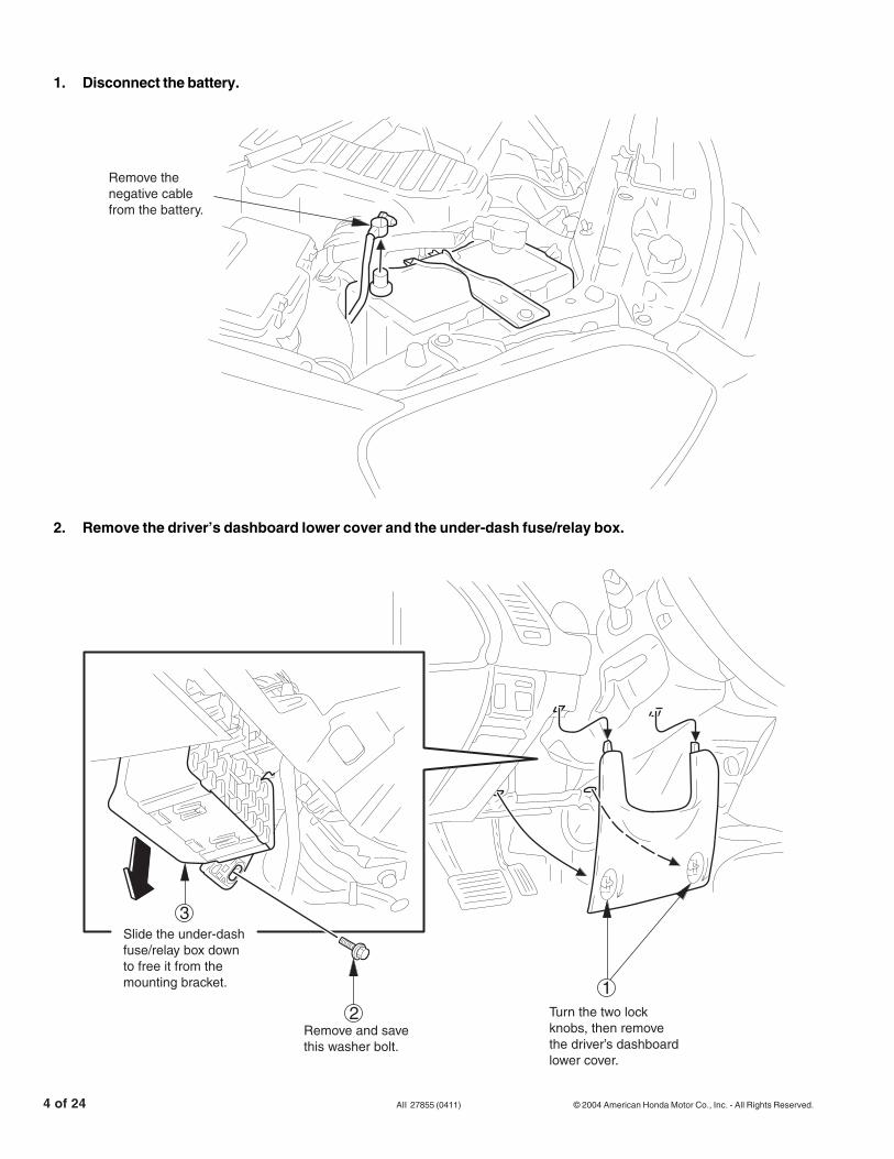
22. Install the A/C compressor belt.
3
4
8
7
1
5
6
2Turn the adjusting bolt until the belt tensionreaches the “New Belt” tension.
Do not overtighten!
New Belt Tension: 830 to 980 N (85 to 100 kg)NOTE: After the A/C kit is installed andthe engine has run for 5 or more minutes(A/C performance test), readjust the belt tothe “Used Belt” tension.
Used Belt Tension: 390 to 540 N (40 to 55 kg).
Torque this bolt toits final torque of44 N.m (33 lb-ft).
Looselyreinstall thealternator.Do nottighten thebolts yet.
Torque this bolt to24 N.m (17 lb-ft).
Fit the belt tension gauge(T/N 07JGG-001010A)onto the A/C compressor belt.
Do not use any other gauge!
Torque this bolt to 44 N.m(33 lb-ft), then recheckthe belt tension.
Install the A/Ccompressor belt.Make sure the beltis properly alignedin the grooves ofthe pulleys.
Apply an initial torqueof 19 N.m (14 lb-ft) tothis bolt.
Torque this bolt toits final torque of44 N.m (33 lb-ft).
Apply an initial torqueof 19 N.m (14 lb-ft) tothis bolt.
Torque this bolt to 44 N.m(33 lb-ft), then recheckthe belt tension.
Torque this bolt to24 N.m (17 lb-ft).
New Belt Tension: 830 to 980 N (85 to 100 lbs.)NOTE: After the A/C kit is installed andthe engine has run for 5 or more minutes(A/C performance test), readjust the belt tothe "Used Belt" tension.
Used Belt Tension: 390 to 540 N (40 to 55 lbs.)

© 2004 American Honda Motor Co., Inc. - All Rights Reserved. AII 27855 (0411) 21 of 24
23. Reinstall the power steering pump.
24. Install the A/C suction line and receiver line B.
Reinstall the P/S fluid reservoirback in its mounting bracket.
Reinstall the adjustingbolt, and turn it by handto get the proper belttension of 390 to 540 N(40 to 50 kg).Do not overtighten!
Reinstall the P/Shose in the bracket.
Fit the belt tension gauge(T/N 07JGG-01010A)onto the P/S belt.Do not use any othergauge!
Reinstall the P/S pumpand its mounting boltsand nuts. Do not tightenthe bolts and nuts yet.
Reinstall the P/S belt.Make sure the belt isproperly aligned in thegrooves of the pulleys.
6
3
1
2
4
7
Torque the twomounting nuts to24 N·m (17 lb-ft),then recheck thebelt tension.
5
2
A/C LINE B
Slide the A/C suction line and receiver line B clamponto the mounting stud. Make sure that the throttle andheater cables are not caught or pinched by the bracket,then install a 6 mm paint-cutting nut (yellow-tinted),90361-SV4-003. Torque the nut to 10 N·m (7 lb-ft).
Connect the A/C suctionline and receiver line Bto the evaporator withone 6 x 30 mm flangebolt (yellow-tinted),95701-06030-08, andtwo 6 mm paint-cuttingnuts (yellow-tinted),90361-SV4-003. Torquethe bolt and nuts to10 N·m (7 lb-ft).
Push the brake booster vacuum hose towardthe engine, then feed the suction hose on theA/C suction line and receiver line B under it.
HEATERVALVE CABLE
THROTTLECABLE
1
4Reinstall the brakebooster hose clampinto the square holeon the bulkhead, thensnap A/C line B into it.
3
Reinstall the adjustingbolt, and turn it by handto get the proper belttension of 390 to 540 N(40 to 50 lbs.)Do not overtighten!

22 of 24 AII 27855 (0411) © 2004 American Honda Motor Co., Inc. - All Rights Reserved.
25. Connect the suction line.
26. Install the discharge hose.
Install the suction hose bracket to the P/S hose bracket with a 6 x 12 mm washer-bolt (yellow-tinted), 93403-06012-08. Torque the bolt to 10 N.m (7 lb-ft).
P/S HOSEBRACKET
Apply refrigerant oil to its O-ring,then connect the suction line to thecompressor with the retained 6 mmflange nut. Torque the nut to 10 N.m(7 lb-ft).
Install the suction hose clamp onto the suction hosebracket, then secure the suction hose in the clamp.
Torque this fitting to 33 N.m (24 lb-ft). Make sure you use a second wrench to hold the other fitting.
Install the suction line bracket with two 6 x 16 mm washer-bolts (gray-colored), 93403-06016-05. Torque the bolts to 10 N.m (7 lb-ft).
Apply refrigerant oil to the suction hose O-ring, then loosely connect the suction hose to the suction line.
Remove and retain this 6 mmflange nut, then remove anddiscard the cap from thesuction side of the compressor.
1
3
5
7
4
2
6
3
Route the dischargehose below thecompressor clutchwire, and up to thecompressor.
COMPRESSORCLUTCH WIRE
SUCTION LINE
Apply refrigerant oil to its O-ring, thenconnect the discharge hose to thecondensor with a 6 x 25 mm flange bolt(yellow-tinted), 95701-06025-08. Torquethe nut to 10 N.m (7 lb-ft).
Remove and retain this 6 mmflange nut, then remove anddiscard the cap from thecompressor.
Apply refrigerant oil to its O-ring, then connect thedischarge hose to the compressor with the retained6 mm flange nut. Torque the nut to 10 N.m (7 lb-ft).
2
4
1
c
Torque this fitting to 33 N.m (24 lb-ft).Make sure you use a second wrenchto hold the other fitting.
Install the suction hose bracketto the P/S hose bracket witha 6 x 12 mm washer-bolt(yellow-tinted), 93403-06012-08.Torque the bolt to 10 N.m (7 lb-ft).
Apply refrigerant oil to is O-ring, thenconnect the suction line to the compressorwith the retained 6 mm flange nut. Torquethe nut to 10 N.m (7 lb-ft).
Apply refrigerant oil to its O-ring, thenconnect the discharge hose to thecondensor with a 6 x 25 mm flange bolt(yellow-tinted), 95701-06025-08. Torquethe nut to 10 N.m (7lb-ft).
Apply refrigerant oil to its O'ring, then connect thedischarge hose to the compressor with the retained6 mm flange nut. Torque the nut to 10 N.m (7 lb-ft).

© 2004 American Honda Motor Co., Inc. - All Rights Reserved. AII 27855 (0411) 23 of 24
Get Parts Group C.
27. Install the power relays and the vehicle harness clip.
28. Attach the labels in the locations shown.
Remove the lid from theunder-hood fuse/relaybox.
Reinstall the fuse/relaybox lid.
Reattach the vehicleharness clips to theirbrackets.
1
23
4
Install the two powerrelays in the socketsshown.
VEHICLE HARNESS
UNDER-HOODSRS LABEL
(Others)
(USA)
(USA)
AIR CONDITIONER SYSTEM

24 of 24 AII 27855 (0411) © 2004 American Honda Motor Co., Inc. - All Rights Reserved.
29. Reinstall the remaining parts.
• Relay assembly and glove box frame• Glove box• Passenger’s dashboard lower cover• Passenger’s kick panel• Center console cover, and reconnect the
accessory power socket or cigarette lighter.• Under-dash fuse/relay box• Driver’s dashboard lower cover• Front bumper and splash shield• Cruise control actuator; tighten the mounting
bolts to 10 N·m (7 lb-ft).• Power steering pressure switch connector• Brake fluid level switch connector• Resonator and air cleaner case• Reconnect the negative cable to the battery.• Check for battery voltage at the accessory
power socket (or cigarette lighter).
30. Do the idle learning procedure.
Whenever the battery or the ECM/PCM isdisconnected, the ECM/PCM must relearn theproper idle air control (IAC) values. To do this,follow this procedure exactly:• Start the engine, and turn off all accessories
(A/C, radio, defogger, etc.).• Warm the engine up to normal operating
temperatures (cooling fans come on twice),then let the engine idle for 10 minutes.
If the above procedure is not done correctly, theengine will have an erratic idle.
31. Evacuate the system.
The HFC-134a and compressor oil used in this A/C system are highly moisture absorbent. Afterinstalling the system, make sure you evacuate itfor at least 15 minutes.
NOTE:
• If low pressure does not reach more than700 mm Hg (27 in-Hg) in 15 minutes, there isprobably a leak in the system. Partially chargethe system, and check for leaks (see step 32).
• If the system is left open, the desiccant in thereceiver tank will become saturated withmoisture, requiring longer evacuation time.
32. Charge the system.• This system requires only the amount of HFC-
134a refrigerant shown below. If you overchargethe system, the engine and the A/C willmalfunction. Do not overcharge! Select theappropriate units of measure for your refrigerantcharging station.
500 to 550 grams
0.50 to 0.55 kilograms
1.1 to 1.2 pounds
17.6 to 19.4 ounces
• Do not add oil to the compressor; a newcompressor already contains enough oil for theentire A/C system. If you are replacingcompressor oil that has leaked out of thesystem, use only Sanden SP-10 oil.
• Using the wrong oil, or mixing different types ofoil, will result in abnormal compressor noise orseizure, or shortened compressor service life.These conditions are not covered by thewarranty policy.
33. Check for leaks.When testing for leaks, follow these guidelines:• Make sure you use a leak detector designed for
A/C systems that use HFC-134a.• To avoid false readings, do not use a tester
designed to detect Freon (CFC-12).• Because HFC-134a is heavier than air, always
check 360° around all fittings.• If you lose or damage an O-ring during A/C
installation, make sure you order the correctreplacement as listed here:
Part Name Part Number ApplicationO-ring, 8 mm 80873-ST7-000 Condenser line
receiver linesO-ring, 5/8" 80871-ST7-000 Suction hose
and lineO-ring, 1/2" 80872-ST7-000 Discharge hose
and line
34. Performance test the A/C system.Refer to Service Bulletin 96-012, Air ConditioningSystem Performance Test, filed under Accessoriesin the old Service Bulletin binder.
35. Readjust the A/C compressor belt to the “UsedBelt” tension: 390 to 540 N (40 to 55 lbs.).Refer to step 22 on page 20.