Embed Size (px)
Citation preview
all pump solutions, Ennerdale Road, Shrewsbury, Shropshire, SY1 3LD.
Intr
oduc
tion
Site access and conditionsIt is the responsibility of the contractor to ensure suitable access to good hard ground that is safe and suitable for off-loading.
Wide/long loadsWhere the tank is of such size that police/ private escort is required delivery times given are estimates only. In the event of delays outside our control eg. police re-routing or escort delays, the extra charges that result will be forwarded to the contractor.
Off-loading/handlingThe contractor is responsible for off-loading. Tank handling during off loading must be carried out with care to prevent rolling off the vehicle. Care must also be exercised to prevent accidental damage from impact or contact with sharp objects.
Tanks should be lifted using slings, not chains or wire ropes. Do not drag tanks along the ground for any distance and avoid jarring or bumps. Do not lift with water in the tank. (See page 1.2).
Note: Where transport height restrictions prevent the tank being loaded in the vertical position on the transport vehicle, the tank will be loaded at 45 degrees or as required to keep within the restrictions. In such cases it will be necessary for the tank to be off loaded onto a level area or well supported planks positioned adjacent to the ‘lift’ points and to support at least four ribs. The area must allow room to enable the tank to be rolled into the vertical position before lifting the tank into the excavation.StorageSet tank on smooth ground free of bricks and sharp objects. Chock/tie down to prevent movement in high winds. (See page 1.2).
Tank dimensions Dimensions given on drawings and literature shall be subject to manufacturing tolerances and should be checked physically prior to installation.
Installation proceduresThe alternative methods of installation depend on the ground conditions, water table, the tank’s location and whether the tank is fitted with feet or not.Installation should be carried out by a competent contractor in accordance with the above procedures, Health & Safety at Work legislation and good building practice. It is not possible to cover every condition in these instructions, therefore if in doubt contact us.
Tank specificationCheck that you have received the correct specification tank. aps underground tanks are available in specifications to suit invert depths, concrete or pea gravel surround and ground water conditions; standard, heavy, extra heavy and special. (See pages 1.3 and 1.4).
For most applications the standard or heavy specifications are adequate. If the tank invert depth and/or water table depth is outside the range we shall be pleased to advise accordingly.
Siting aps septic tanksBritish Standard BS 6297: 1983 recommends that sewage treatment works should be as far from habitable buildings as is economically practicable. The direction of the prevailing wind should be considered in relation to any properties when siting the works.
In accordance with the Building Regulations 2000. H2 2002 edition aps septic tanks should be sited at least 7m from any habitable parts of buildings, and preferably downslope.
The tank should not be installed near a road or driveway, where it could be subjected to high external loads, unless the installation is designed to withstand such loadings so they are not transferred to the tank shell.
Where the tank is to emptied using a tanker, it should be sited within
30m of a vehicle access provided that the invert level of the septic tank is no more than 3m below the level of the vehicle access. This distance may need to be reduced where the depth to the invert of the tank is more than 3m. Thereshould also be a clear route for the hose such that the tank can be emptied and cleaned without hazard to the building occupants and without the contents being taken through a dwelling or place of work.
Siting aps cesspoolsaps cesspools should be sited at least 7m from any habitable building and preferably downslope. They should however be sited within 30m of a sludge removal tanker access and at such levels and position to operate and without hazard to the building occupants.
Extension access shaftsCheck if extension shafts are required. These are available in 500mm high increments.
Note: Where coalescer units or pumps are incorporated that require guide rails, or ladders are fitted, the height of the extension access shaft/s should be measured accurately before ordering.
Health and safetyInstallation should be carried out by a competent contractor in accordance with the above procedures, Health & safety at Work legislation and good building practice. A warning notice should be visible at the top of each access shaft – ‘danger, harmful fumes’ and ‘respirators must be worn in this tank’. Before entering persons must be qualified in accordance with ‘confined space’ requirements.
aps Packaged Pump Stations, underground tanks and stormwater attenuation tanks must be installed according to these instructions.
The local authority and the local region of the Environment Agency should also be consulted as to whether any particular code applies to installation. Failure to follow these installation instructions will make void our warranty and may result in tank failure.
T: +44 (0) 1743 465463 F: +44 (0) 1743 452050 E: [email protected]
Lifting, handling and
storage
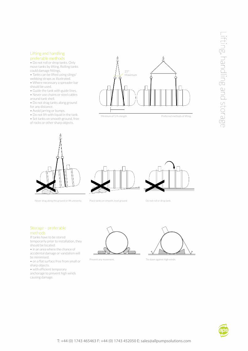
Lifting and handling preferable methods• Do not roll or drop tanks. Only move tanks by lifting. Rolling tanks could damage fittings.• Tanks can be lifted using slings/ webbing straps as illustrated.• Where necessary a spreader bar should be used.• Guide the tank with guide lines.• Never use chains or steel cables around tank shell.• Do not drag tanks along ground for any distance.• Avoid jarring or bumps.• Do not lift with liquid in the tank.• Set tanks on smooth ground, free of rocks or other sharp objects.
Storage – preferable methodsIf tanks have to be stored temporarily prior to installation, they should be located:• in an area where the chance of accidental damage or vandalism will be minimised.• on a flat surface free from small or sharp objects.• with efficient temporary anchorage to prevent high winds causing damage.
25° Maximum
Minimum of 1/4 x length Preferred methods of lifting.
Never drag along the ground or lift unevenly. Place tanks on smooth, level ground Do not roll or drop tank.
Prevent any movement. Tie down against high winds.

all pump solutions, Ennerdale Road, Shrewsbury, Shropshire, SY1 3LD.
Surr
ound
s Specifications to suit invert depths and ground water conditions – pea gravel and concrete surrounds
High water table Well drained ground
X depth of water table Y maximum depth
High water table Well drained ground
X depth of water table Y maximum depth
Standard tanks Heavy, extra heavy and special tanks
1800mm dia with pea gravel surround 2600mm dia with pea gravel surround
1800mm dia with concrete surround 2600mm dia with concrete surround
T: +44 (0) 1743 465463 F: +44 (0) 1743 452050 E: [email protected]
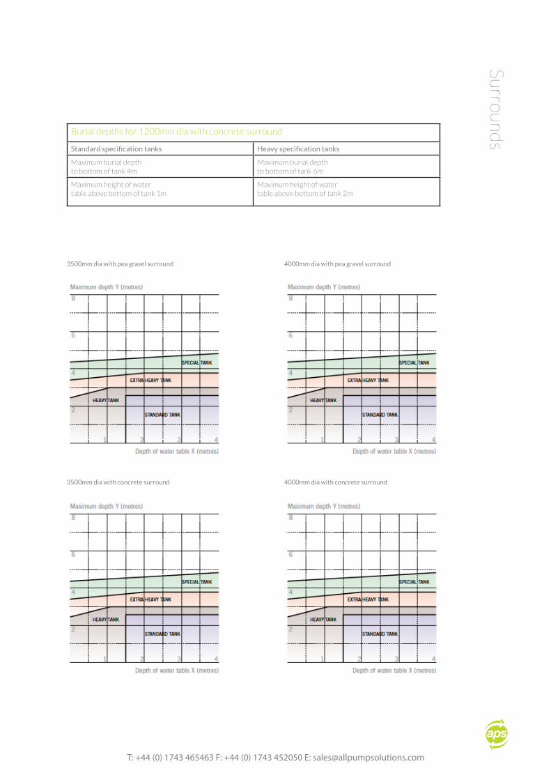
Burial depths for 1200mm dia with concrete surround
Standard specification tanks Heavy specification tanks
Maximum burial depthto bottom of tank 4m
Maximum burial depthto bottom of tank 6m
Maximum height of watertable above bottom of tank 1m
Maximum height of watertable above bottom of tank 2m
Surrounds
3500mm dia with pea gravel surround 4000mm dia with pea gravel surround
3500mm dia with concrete surround 4000mm dia with concrete surround
all pump solutions, Ennerdale Road, Shrewsbury, Shropshire, SY1 3LD.
Typi
cal I
nsta
llati
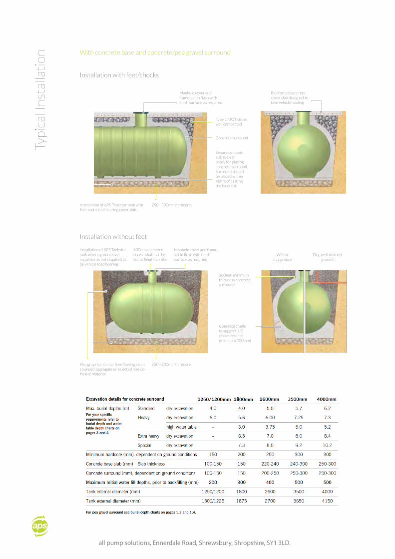
onWith concrete base and concrete/pea gravel surround
Installation with feet/chocks
Installation without feet
Manhole cover and frame, set in flush with finish surface, as required
Type 1 MOT stone, well compacted
Concrete surround
Ensure concrete slab is clean ready for placing concrete surround.Surround should be placed within 48hrs of casting the base slab
Reinforced concrete cover slab designed to take vehicle loading
Installation of APS Tankstor tank with feet and a load bearing cover slab.
250 - 300mm hardcore
250 - 300mm hardcorePea gravel or similar free flowing clean rounded aggregate or selected non-co-hesive material
Concrete cradle to support 1/3 circumference (minimum 200mm)
200mm minimum thickness concrete surround
Installation of APS Tankstor tank where ground over installtion is not required to be vehicle load bearing
600mm diameter access shaft can be cut to length on site
Manhole cover and frame, set in flush with finish surface, as requried
Wet or clay ground
Dry, well-drained ground
T: +44 (0) 1743 465463 F: +44 (0) 1743 452050 E: [email protected]
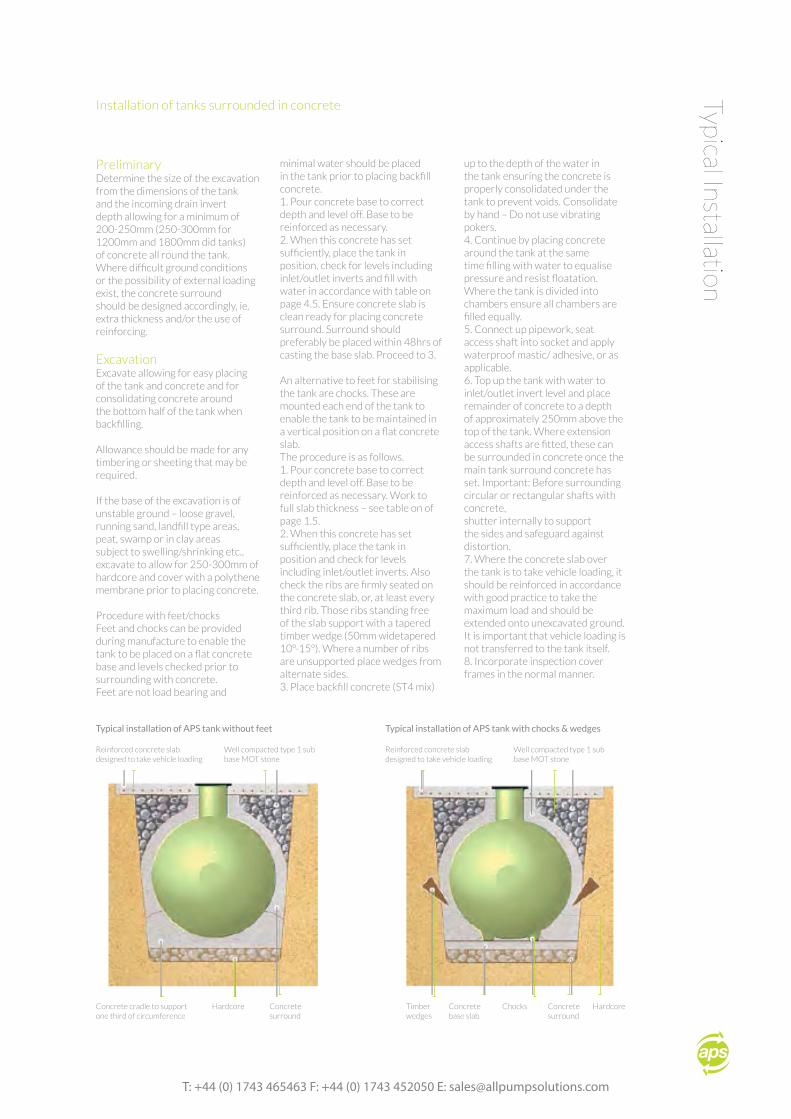
Typical InstallationInstallation of tanks surrounded in concrete
PreliminaryDetermine the size of the excavation from the dimensions of the tank and the incoming drain invert depth allowing for a minimum of 200-250mm (250-300mm for 1200mm and 1800mm did tanks) of concrete all round the tank. Where difficult ground conditions or the possibility of external loading exist, the concrete surround should be designed accordingly, ie. extra thickness and/or the use of reinforcing.
ExcavationExcavate allowing for easy placing of the tank and concrete and for consolidating concrete around the bottom half of the tank when backfilling.
Allowance should be made for any timbering or sheeting that may be required.
If the base of the excavation is of unstable ground – loose gravel, running sand, landfill type areas, peat, swamp or in clay areas subject to swelling/shrinking etc., excavate to allow for 250-300mm of hardcore and cover with a polythene membrane prior to placing concrete.
Procedure with feet/chocksFeet and chocks can be provided during manufacture to enable the tank to be placed on a flat concrete base and levels checked prior to surrounding with concrete.Feet are not load bearing and
minimal water should be placed in the tank prior to placing backfill concrete.1. Pour concrete base to correct depth and level off. Base to be reinforced as necessary.2. When this concrete has set sufficiently, place the tank in position, check for levels including inlet/outlet inverts and fill with water in accordance with table on page 4.5. Ensure concrete slab is clean ready for placing concrete surround. Surround should preferably be placed within 48hrs of casting the base slab. Proceed to 3.
An alternative to feet for stabilising the tank are chocks. These are mounted each end of the tank to enable the tank to be maintained in a vertical position on a flat concrete slab.The procedure is as follows.1. Pour concrete base to correct depth and level off. Base to be reinforced as necessary. Work to full slab thickness – see table on of page 1.5.2. When this concrete has set sufficiently, place the tank in position and check for levels including inlet/outlet inverts. Also check the ribs are firmly seated on the concrete slab, or, at least every third rib. Those ribs standing free of the slab support with a tapered timber wedge (50mm widetapered 10º-15º). Where a number of ribs are unsupported place wedges from alternate sides.3. Place backfill concrete (ST4 mix)
up to the depth of the water in the tank ensuring the concrete is properly consolidated under the tank to prevent voids. Consolidate by hand – Do not use vibrating pokers.4. Continue by placing concrete around the tank at the same time filling with water to equalise pressure and resist floatation.Where the tank is divided into chambers ensure all chambers are filled equally.5. Connect up pipework, seat access shaft into socket and apply waterproof mastic/ adhesive, or as applicable.6. Top up the tank with water to inlet/outlet invert level and place remainder of concrete to a depth of approximately 250mm above the top of the tank. Where extension access shafts are fitted, these can be surrounded in concrete once the main tank surround concrete has set. Important: Before surrounding circular or rectangular shafts with concrete,shutter internally to support the sides and safeguard against distortion.7. Where the concrete slab over the tank is to take vehicle loading, it should be reinforced in accordance with good practice to take the maximum load and should be extended onto unexcavated ground. It is important that vehicle loading is not transferred to the tank itself.8. Incorporate inspection cover frames in the normal manner.
Reinforced concrete slabdesigned to take vehicle loading
Typical installation of APS tank without feet
Well compacted type 1 sub base MOT stone
Concrete cradle to support one third of circumference
Hardcore Concretesurround
Reinforced concrete slabdesigned to take vehicle loading
Well compacted type 1 sub base MOT stone
Typical installation of APS tank with chocks & wedges
Timberwedges
Chocks Concretesurround
Concretebase slab
Hardcore
all pump solutions, Ennerdale Road, Shrewsbury, Shropshire, SY1 3LD.
Typi
cal I
nsta
llati
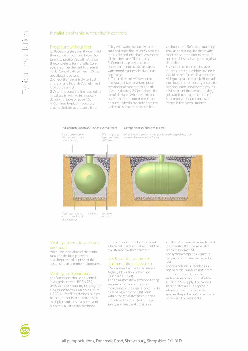
onInstallation of tanks surrounded in concrete
Procedure without feet1. Place concrete along the centre of the excavation base and lower the tank into position ‘puddling’ it into the concrete to form cradle. Con-solidate under the tank to prevent voids. Consolidate by hand – Do not use vibrating pokers.2. Check the tank is truly vertical and level and that inlet/outlet invert levels are correct.3. After the concrete has reached its initial set, fill with water in accor-dance with table on page 4.5.4. Continue by placing concrete around the tank at the same time
filling with water to equalise pres-sure and resist floatation. Where the tank is divided into chambers ensure all chambers are filled equally.5. Connect up pipework, seat access shaft into socket and apply waterproof mastic/adhesive, or as applicable.6. Top up the tank with water to inlet/outlet invert level and place remainder of concrete to a depth of approximately 250mm above the top of the tank. Where extension access shafts are fitted, these can be surrounded in concrete once the main tank surround concrete has
set. Important: Before surrounding circular or rectangular shafts with concrete, shutter internally to sup-port the sides and safeguard against distortion.7. Where the concrete slab over the tank is to take vehicle loading, it should be reinforced, in accordance with good practice, to take the maxi-mum load. The reinforcing should be extended onto unexcavated ground. It is important that vehicle loading is not transferred to the tank itself.8. Incorporate inspection cover frames in the normal manner.
Venting aps septic tanks and cesspools Adequate ventilation of the septic tank and the inlet pipework shall be provided to prevent the accumulation of fermentation gases.
Venting aps Separators aps Separators should be vented in accordance with BS EN 752 (BS8301:1985 Building Drainage) or Health and Safety Guidance Notice HS (G) 41 for filling stations, subject to local authority requirements. In multiple chamber separators, vent pipework must not be combined
into a common stack below a point where pollutants contained could be transferred to other chambers.
aps Separator automatic alarm/monitoring system(Requirement of the Environment Agency’s Pollution Prevention Guidelines PPG3)The aps automatic alarm/monitoring system provides continuous monitoring of the separator contents by sensing when the light liquid within the separator has filled to a predetermined level (with design safety margins), and provides a
simple audio-visual warning to alert the operator that the separator needs to be emptied.The system comprises 2 parts: a compact control unit and a probe unit.The control unit is installed in a non-hazardous area remote from the probe. It is self-contained and requires only a normal 240v AC electrical supply. The control incorporates a ATEX approved intrinsically safe circuit, which enables the probe unit to be used in Zone Zero Environments.
Reinforced concrete slab designed to take vehicle loading
Typical installation of APS tank without feet
Well compacted type 1 sub base MOT stone
When the concrete surround has fully cured, cesspool should be completely emptied ready for use.
Cesspool tanks/ silage tanks etc.
Concrete cradle to support one third of circumference
Hardcore Concretesurround
T: +44 (0) 1743 465463 F: +44 (0) 1743 452050 E: [email protected]
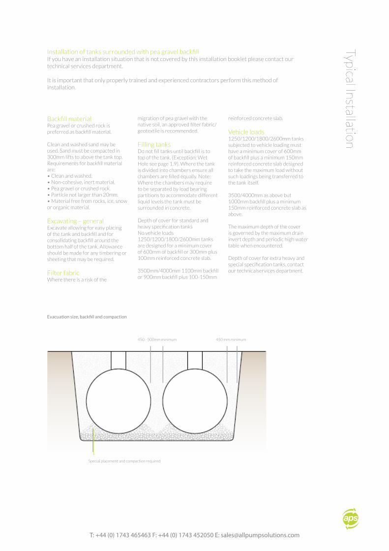
Typical InstallationInstallation of tanks surrounded with pea gravel backfillIf you have an installation situation that is not covered by this installation booklet please contact our technical services department. It is important that only properly trained and experienced contractors perform this method of installation.
Backfill materialPea gravel or crushed rock is preferred as backfill material.
Clean and washed sand may be used. Sand must be compacted in 300mm lifts to above the tank top.Requirements for backfill material are:• Clean and washed.• Non-cohesive, inert material.• Pea gravel or crushed rock.• Particle not larger than 20mm.• Material free from rocks, ice, snow or organic material.
Excavating – generalExcavate allowing for easy placing of the tank and backfill and for consolidating backfill around the bottom half of the tank. Allowance should be made for any timbering or sheeting that may be required.
Filter fabricWhere there is a risk of the
migration of pea gravel with the native soil, an approved filter fabric/geotextile is recommended.
Filling tanksDo not fill tanks until backfill is to top of the tank. (Exception; Wet Hole see page 1.9). Where the tank is divided into chambers ensure all chambers are filled equally. Note: Where the chambers may require to be separated by load bearing partitions to accommodate different liquid levels the tank must be surrounded in concrete.
Depth of cover for standard and heavy specification tanksNo vehicle loads1250/1200/1800/2600mm tanks are designed for a minimum cover of 600mm of backfill or 300mm plus 100mm reinforced concrete slab.
3500mm/4000mm 1100mm backfill or 900mm backfill plus 100-150mm
reinforced concrete slab.
Vehicle loads1250/1200/1800/2600mm tanks subjected to vehicle loading must have a minimum cover of 600mm of backfill plus a minimum 150mm reinforced concrete slab designed to take the maximum load without such loadings being transferred to the tank itself.
3500/4000mm as above but 1000mm backfill plus a minimum 150mm reinforced concrete slab as above.
The maximum depth of the cover is governed by the maximum drain invert depth and periodic high water table when encountered.
Depth of cover for extra heavy and special specification tanks, contact our technicalservices department.
450 - 500mm minimum
Evacuation size, backfill and compaction
450 mm minimum
Special placement and compaction required
all pump solutions, Ennerdale Road, Shrewsbury, Shropshire, SY1 3LD.
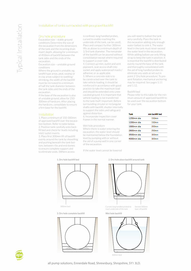
Dry hole procedureExcavation size – stable ground conditions Determine the size of the excavation from the dimensions of the tank and the incoming drain invert depth, allowing for a minimum of 450mm of backfill between the tank sides and the ends of the excavation.Excavation size – unstable ground conditionsWhere the ground is unstable, eg. landfill type areas, peat, swamp or in clay areas subject to swelling/shrinking, the width of the backfill must be increased to a minimum of half the tank diameter between the tank sides and the ends of the excavation.If the base of the excavation is also of unstable ground, allow for 250-300mm of hardcore. After placing the hardcore, consolidate to ensure a firm base for the backfill.
Installation1. Place a minimum of 150-300mm of approved backfill over the excava-tion bottom. Refer to table below.2. Position tank carefully onto back-fill bed and check for levels including inlet/ outlet inverts.3. Place first 300mm lift of backfill evenly around the tank by shovelling and pushing beneath the tank bot-tom, between ribs and end domes to ensure complete support and to eliminate voids. (Where access
is confined, long handled probes, curved to enable reaching the underside of the tank, can be used). Place and compact further 300mm lifts as above to a minimum depth of 1/3rd tank diameter. The remainder of the backfill can be poured without consolidation except where required to support a cover slab.4. Connect up inlet, outlet and vent pipework, seat access shaft into socket and apply waterproof mastic/adhesive, or as applicable.5. Where a concrete slab is to be constructed over the tank to take vehicle loading, it should be reinforced in accordance with good practice to take the maximum load and should be extended onto unex-cavated ground. It is important that vehicle loading is not transferred to the tank itself. Important: Before surrounding circular or rectangular shafts with backfill, shutter internally to support the sides and safeguard against distortion.6. Incorporate inspection cover frames in the normal manner.
Wet hole procedureWhere there is water entering the excavation, the water level should be maintained below the foundation level by pumping with or without the aid of a pump well in one corner of the excavation.
If the water level cannot be lowered
you will need to ballast the tank very carefully. Place the tank in the excavation adding only enough water ballast to sink it. The water level in the tank must never exceed the water level in the excavation. While adding ballast use only lifting strap to keep the tank in position. It is essential the backfill is distributed evenly round the base of the tank and thoroughly consolidated with the aid of long handled probes to eliminate any voids as set out in point 3 ‘Dry hole procedure’. To pre-vent flotation, mechanical anchoring may be required. See pages 1.11 and 1.12.
Backfill bedPlease refer to this table for the min-imum amount of approved backfill to be used over the excavation bottom for your tank.
Typi
cal I
nsta
llati
onInstallation of tanks surrounded with pea gravel backfill
300mm bed
1. Dry hole backfill bed 2. Dry hole place backfill around tank
Curved, long handled probed to reach underside of the tank
Second 300mm layer of backfill
3. Dry hole complete backfill Wet hole backfill
300mm bed
T: +44 (0) 1743 465463 F: +44 (0) 1743 452050 E: [email protected]
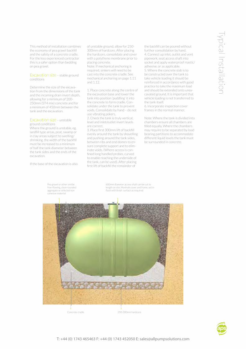
This method of installation combines the economy of pea gravel backfill and the safety of a concrete cradle. For the less experienced contractor this is a safer option than bedding on pea gravel.
Excavation size – stable ground conditions
Determine the size of the excava-tion from the dimensions of the tank and the incoming drain invert depth, allowing for a minimum of 200-250mm (ST4 mix) concrete and for a minimum of 450mm between the tank and the excavation.
Excavation size – unstable ground conditionsWhere the ground is unstable, eg. landfill type areas, peat, swamp or in clay areas subject to swelling/shrinking, the width of the backfill must be increased to a minimum of half the tank diameter between the tank sides and the ends of the excavation.
If the base of the excavation is also
of unstable ground, allow for 250-300mm of hardcore. After placing the hardcore, consolidate and cover with a polythene membrane prior to placing concrete.Note: If mechanical anchoring is required, sinkers will need to be cast into the concrete cradle. See mechanical anchoring on page 1.11 and 1.12.
1. Place concrete along the centre of the excavation base and lower the tank into position ‘puddling’ it into the concrete to form cradle. Con-solidate under the tank to prevent voids. Consolidate by hand – do not use vibrating pokers.2. Check the tank is truly vertical, level and inlet/outlet invert levels are correct.3. Place first 300mm lift of backfill evenly around the tank by shovelling and pushing around the tank sides, between ribs and end domes to en-sure complete support and to elim-inate voids. (Where access is con-fined long handled probes, curved to enable reaching the underside of the tank, can be used). After placing first lift of backfill the remainder of
the backfill can be poured without further consolidation by hand.4. Connect up inlet, outlet and vent pipework, seat access shaft into socket and apply waterproof mastic/adhesive, or as applicable.5. Where the concrete slab is to be constructed over the tank to take vehicle loading it should be reinforced in accordance with good practice to take the maximum load and should be extended onto unex-cavated ground. It is important that vehicle loading is not transferred to the tank itself.6. Incorporate inspection cover frames in the normal manner.
Note: Where the tank is divided into chambers ensure all chambers are filled equally. Where the chambers may require to be separated by load bearing partitions to accommodate different liquid levels the tank must be surrounded in concrete.
Typical Installation
Pea gravel or other similar, free-flowing, clean rounded aggregate or selected non cohesive material
600mm diameter access shaft can be cut to length on site. Manhole cover and frame, set in flush with finish surface as required
Concrete cradle 250-300mm hardcore
all pump solutions, Ennerdale Road, Shrewsbury, Shropshire, SY1 3LD.
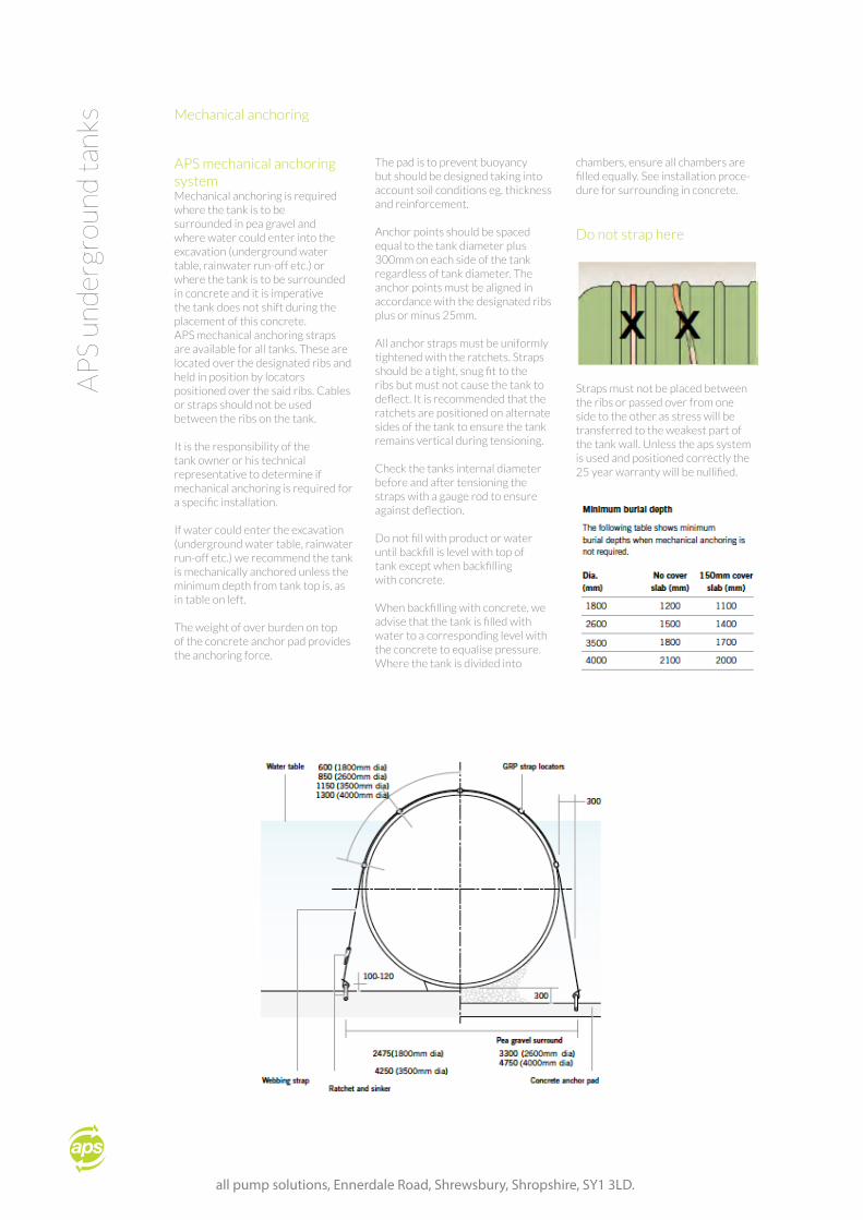
APS mechanical anchoring systemMechanical anchoring is required where the tank is to be surrounded in pea gravel and where water could enter into the excavation (underground water table, rainwater run-off etc.) or where the tank is to be surrounded in concrete and it is imperative the tank does not shift during the placement of this concrete.APS mechanical anchoring straps are available for all tanks. These are located over the designated ribs and held in position by locators positioned over the said ribs. Cables or straps should not be used between the ribs on the tank.
It is the responsibility of the tank owner or his technical representative to determine if mechanical anchoring is required for a specific installation.
If water could enter the excavation (underground water table, rainwater run-off etc.) we recommend the tank is mechanically anchored unless the minimum depth from tank top is, as in table on left.
The weight of over burden on top of the concrete anchor pad provides the anchoring force.
The pad is to prevent buoyancy but should be designed taking into account soil conditions eg. thickness and reinforcement.
Anchor points should be spaced equal to the tank diameter plus 300mm on each side of the tank regardless of tank diameter. The anchor points must be aligned in accordance with the designated ribs plus or minus 25mm.
All anchor straps must be uniformly tightened with the ratchets. Straps should be a tight, snug fit to the ribs but must not cause the tank to deflect. It is recommended that the ratchets are positioned on alternate sides of the tank to ensure the tank remains vertical during tensioning.
Check the tanks internal diameter before and after tensioning the straps with a gauge rod to ensure against deflection.
Do not fill with product or water until backfill is level with top of tank except when backfilling with concrete.
When backfilling with concrete, we advise that the tank is filled with water to a corresponding level with the concrete to equalise pressure. Where the tank is divided into
chambers, ensure all chambers are filled equally. See installation proce-dure for surrounding in concrete.
Do not strap here
Straps must not be placed between the ribs or passed over from one side to the other as stress will be transferred to the weakest part of the tank wall. Unless the aps system is used and positioned correctly the 25 year warranty will be nullified.
AP
S un
der
grou
nd t
anks Mechanical anchoring
T: +44 (0) 1743 465463 F: +44 (0) 1743 452050 E: [email protected]
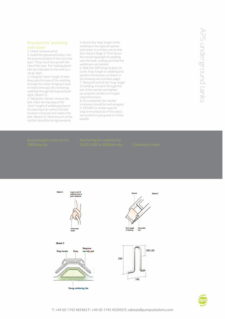
Procedure for ‘anchoring’ tanks down1. Check contents of kit.2. Install the galvanised sinker into the precast pockets of the concrete base. These must line up with the ribs of the tank. The ‘holding down’ ribs are indicated on the tank by a ‘strap’ label.3. Using the ‘short’ length of web-bing, pass the loop of the webbing through the sinker bringing it back on itself, then pass the remaining webbing through the loop and pull tight. (Sketch 1).4. Taking the ratchet, remove the bolt. Place the top loop of the ‘short’ length of webbing between the opening from where the bolt has been removed and replace the bolt. (Sketch 2). Note the arm of the ratchet should be facing outwards.
5. Attach the ‘long’ length of the webbing to the opposite galvan-ised sinker in a similar way to that described in Stage 3. Then throw the remaining length of webbing over the tank, making sure that the webbing is not twisted.6. Slide the GRP strap locators on to the ‘long’ length of webbing and position the locators as shown in the drawing (see previous page).7. Taking the end of the ‘long’ length of webbing, thread it through the slot of the ratchet and tighten up using the ratchet arm to give required tension.8. On completion the ratchet tensioners should be well wrapped in ‘DENSO’ or similar tape for long-term protection if the tank is surrounded in pea gravel or similar backfill.
AP
S underground
tanks
Anchoring kit contents for1800mm dia:
• Short length of webbing x 1• Long length of webbing x 1• Galvanised sinker x 2• Ratchet x 1• GRP strap locators x 3• Anchoring kit contents for• 2600, 3500 &4000mm dia
Anchoring kit contents for2600,3500 & 4000mm dia:
• Short length of• webbing x 1 Long length of• webbing x 1 Galvanised• sinker x 2 Ratchet x 1 GRP• strap locators x 5
Galvanised sinker
Top of sinker shouldprotrude 100-120mmabove concrete slab.
all pump solutions, Ennerdale Road, Shrewsbury, Shropshire, SY1 3LD.
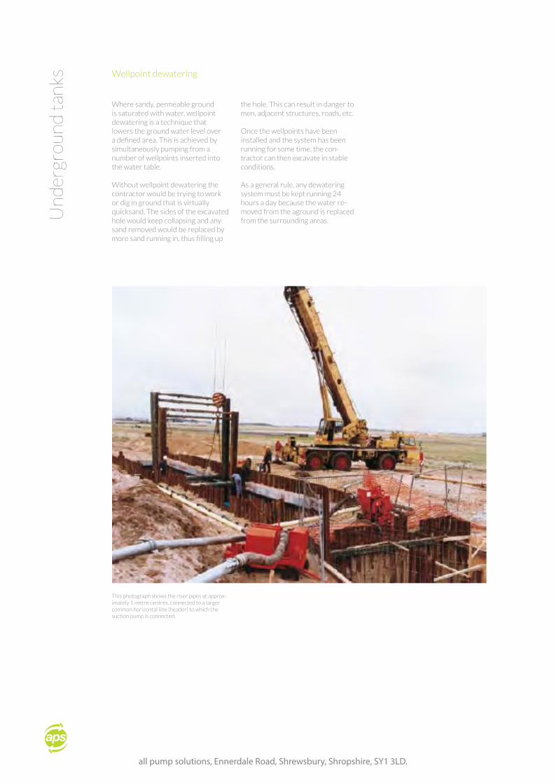
Where sandy, permeable ground is saturated with water, wellpoint dewatering is a technique that lowers the ground water level over a defined area. This is achieved by simultaneously pumping from a number of wellpoints inserted into the water table.
Without wellpoint dewatering the contractor would be trying to work or dig in ground that is virtually quicksand. The sides of the excavated hole would keep collapsing and any sand removed would be replaced by more sand running in, thus filling up
the hole. This can result in danger to men, adjacent structures, roads, etc.
Once the wellpoints have been installed and the system has been running for some time, the con-tractor can then excavate in stable conditions.
As a general rule, any dewatering system must be kept running 24 hours a day because the water re-moved from the aground is replaced from the surrounding areas.U
nder
grou
nd t
anks Wellpoint dewatering
This photograph shows the riser pipes at approx-imately 1 metre centres, connected to a larger common horizontal line (header) to which the suction pump is connected.
T: +44 (0) 1743 465463 F: +44 (0) 1743 452050 E: [email protected]
Installation of tanks surrounded with pea gravel backfill
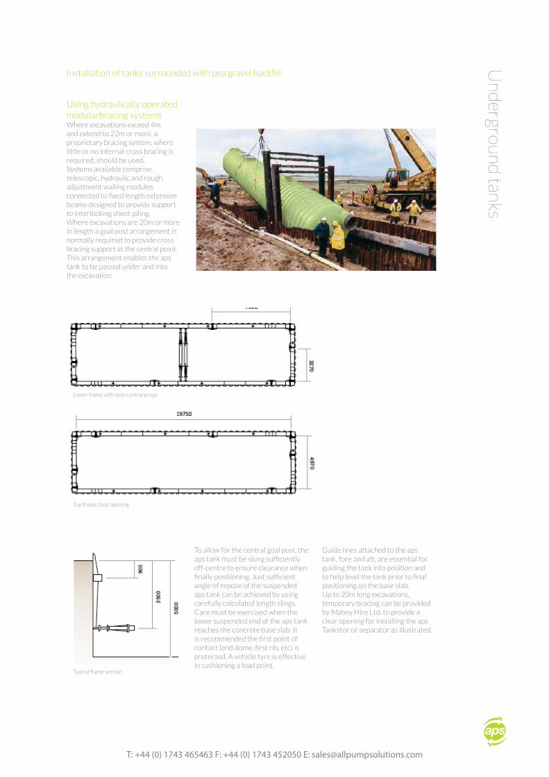
Using hydraulically operated modularbracing systemsWhere excavations exceed 4m and extend to 22m or more, a proprietary bracing system, where little or no internal cross bracing is required, should be used.Systems available comprise telescopic, hydraulic and rough adjustment walling modules connected to fixed length extension beams designed to provide support to interlocking sheet piling.Where excavations are 20m or more in length a goal post arrangement is normally required to provide cross bracing support at the central point. This arrangement enables the aps tank to be passed under and into the excavation.
Und
erground tanks
To allow for the central goal post, the aps tank must be slung sufficiently off-centre to ensure clearance when finally positioning. Just sufficient angle of repose of the suspended aps tank can be achieved by using carefully calculated length slings.Care must be exercised when the lower suspended end of the aps tank reaches the concrete base slab. It is recommended the first point of contact (end dome, first rib, etc) is protected. A vehicle tyre is effective in cushioning a load point.
Guide lines attached to the aps tank, fore and aft, are essential for guiding the tank into position and to help level the tank prior to final positioning on the base slab.Up to 20m long excavations, temporary bracing can be provided by Mabey Hire Ltd. to provide a clear opening for installing the aps Tankstor or separator as illustrated.
Lower frame with twin central props
Top frame clear opening
Typical frame section
all pump solutions, Ennerdale Road, Shrewsbury, Shropshire, SY1 3LD.
Com
mis
sion
ing
Tanks, Site Pipework & Cable Ducts - Installation by contractorThe products supplied are generally installed by the customer or the appointed contractor which in the case of a package pumping station would include the underground and/ or above ground pipework, kiosk plinth and mounting the kiosk, underground cable ducts with drawstrings and conduit or cable trays for above ground cabling.Installation instructions are supplied with every tank or chamber, Copies are available on request.The cables supplied with the pump/s are normally 10m or 20m to special order. Any additional cabling required shall be supplied and fitted by the customer prior to the commissioning site visit.
Commissioning by special products divisionAPS Products, or their appointed contractor, will undertake the commissioning which comprises the
placing of the pumps in the tank and pulling through the cable/s to the control panel, placing the control float switches in the tank and commissioning the system.
Commissions costThe cost of commissioning is usually included in the overall price for the system. the benefit is that the cost is fixed for a period of six months. However, the full payment including the cost of commissioning has been undertaken or not.Where the commissioning cost is a separate charge, APS Products shall be entitled to revise the charge/s to cover any increases in the cost of labour and materials at the time of commissioning.
Site readiness for commissioningPrior to arranging the date for commissioning the ‘Site readiness for commissioning’ form shall be completed and returned to APS Products to ensure the installation,
power supply and other preparatory work required is completed.This is to ensure the commissioning visit is not aborted and extra charges for a return visit are not necessary.One requirement is for water to be available in order to physically test the system for pumping operation, output and level controls.Without the water or the media required to be pumped, the system can only be commissioned to theoretically operate. If after commissioning the system requires a further visit to adjust operation when the water or media is present, a further site visit charge will be applied.
BreakdownsAfter commissioning any further work required as a result of misuse, neglect, wilful damage, vandalism and blockages, shall be charged at current rates.
During installation & commissioningCharges will be raised for or in addition to the agreed commissioning or service charge where:• Site induction takes longer than 30 minutes• Electricity supply is inadequate or fails• Investigating as a result of a request to attend site but no fault found • Visits to site where access
is prevented by others, safety measures not in place or for other reasons beyond the control of APS Products• Hours out of normal working hours will be charged according to the overtime rates applying• Inability to undertake commissioning or servicing if dislodging or jetting is required prior to commencement.
Excluded in the commissioning/servicing:• Overspill clear up• Over pumping• Cost arising out of a pollution incident • Pipework or other leaks outside the pumping/valve chamber supplied
• Any internal damage that has occurred during installation by others.
Service Visits After commissioning it is recommended a service of the pumps and specified associated equipment at intervals of approximately 12 months.
all pump solutions, Ennerdale Road, Shrewsbury, Shropshire, SY1 3LD.
Add
itio
nal C
harg
es
T: +44 (0) 1743 465463 F: +44 (0) 1743 452050 E: [email protected]
GR
P vertical pum
p station
T: +44 (0) 1743 465463 F: +44 (0) 1743 452050 E: [email protected]
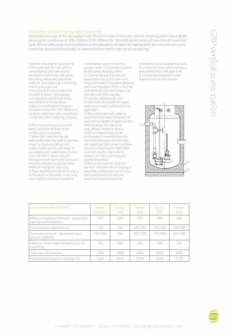
Installation of tanks surrounded in concreteDetermine the size of the excavation from the dimensions of the tank and the incoming drain invert depth allowing for a minimum of 200-250mm (250-300mm for 500/600 series tanks) of concrete all round the tank. Where difficult ground conditions or the possibility of external loading exist, the concrete surround should be designed accordingly, i.e. extra thickness and/or the use of reinforcing.
Excavate allowing for easy placing of the tank and concrete and for consolidating concrete around the bottom half of the tank when backfilling. Allowance should be made for any timbering or sheeting that may be required.If the base of the excavation is of unstable ground – loose gravel, running sand, landfill type areas, peat, swamp or in clay areas subject to swelling/shrinking etc., excavate to allow for 250-300mm of hardcore and cover with a polythene membrane prior to placing concrete. 1. Pour concrete base to correct depth and level off. Base to be reinforced as necessary.2. When this concrete has set sufficiently, place the tank in position, check for levels including inlet/ outlet inverts and fill with water in accordance with table below. Ensure concrete slab is clean ready for placing concrete surround. Surround should preferably be placed within 48hrs of casting the base slab.3. Place backfill concrete (ST4 mix) up to the depth of the water in the tank ensuring the concrete is properly
consolidated under the tank to prevent voids. Consolidate by hand – do not using vibrating pokers.4. Continue by placing concrete around the tank at the same time filling with water to equalise pressure and resist floatation. Where the tank is divided into chambers ensure all chambers are filled equally.5. Connect up pipework, seat access shaft into socket and apply waterproof mastic/ adhesive, or as applicable.6. Top up the tank with water to invert level and place remainder of concrete to a depth of approximately 250mm above the top of the tank. Where extension access shafts are fitted, these can be surrounded in concrete once the main tank surround concrete has set. Important: Before surrounding circular or rectangular shafts with concrete, shutter internally to support the sides and safeguard against distortion.7. Where the concrete slab over the tank is to take vehicle loading, it should be reinforced in accordance with good practice to take the maximum load and should be
extended onto unexcavated ground. It is important that vehicle loading is not transferred to the tank itself.8. Incorporate inspection cover frames in the normal manner.
Excavation details (mm) Series100/200
Series 300
Series 400
Series 500
Series 600
Minimum hardcore thickness – dependent upon ground conditions
150 200 250 300 300
Concrete base slab thickness 150 150 220-240 240-300 250-300
Concrete surround – dependent upon ground conditions
100-150 150 200-250 250-300 250-300
Maximum initial water fill depths prior to backfilling
200 300 400 500 500
Tank internal diameters 1200 1800 2600 3500 4000
Tank external diameter including ribs 1225 1875 2700 3650 4150
all pump solutions, Ennerdale Road, Shrewsbury, Shropshire, SY1 3LD.
Com
mis
sion
ing
Req
uest
For
m Contact Name: Contact Number:
Site Address:
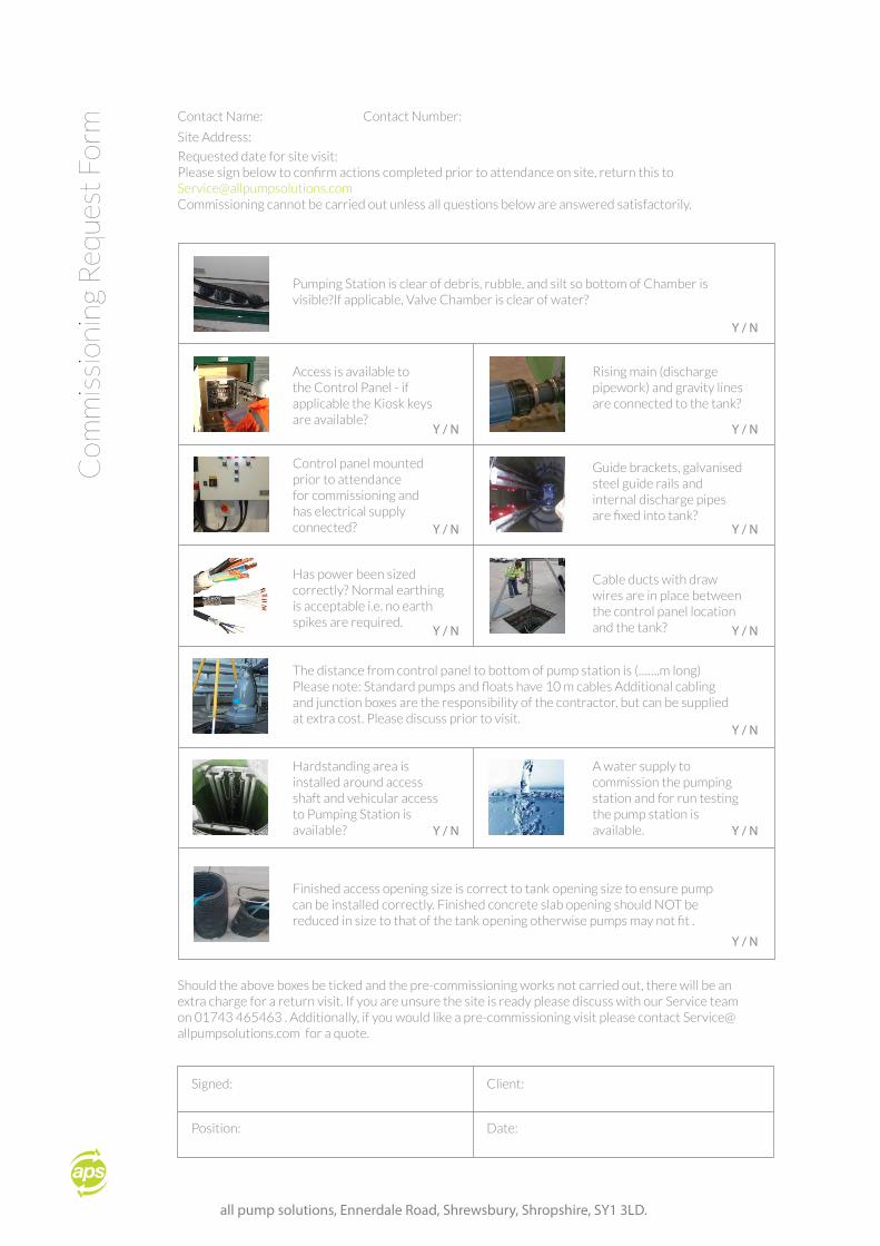
Requested date for site visit:Please sign below to confirm actions completed prior to attendance on site, return this [email protected] cannot be carried out unless all questions below are answered satisfactorily.
Should the above boxes be ticked and the pre-commissioning works not carried out, there will be an extra charge for a return visit. If you are unsure the site is ready please discuss with our Service team on 01743 465463 . Additionally, if you would like a pre-commissioning visit please contact [email protected] for a quote.
Access is available to the Control Panel - if applicable the Kiosk keys are available?
Control panel mounted prior to attendance for commissioning and has electrical supply connected?
Has power been sized correctly? Normal earthing is acceptable i.e. no earth spikes are required.
Rising main (discharge pipework) and gravity lines are connected to the tank?
Guide brackets, galvanised steel guide rails and internal discharge pipes are fixed into tank?
Cable ducts with draw wires are in place between the control panel location and the tank?
The distance from control panel to bottom of pump station is (…….m long) Please note: Standard pumps and floats have 10 m cables Additional cabling and junction boxes are the responsibility of the contractor, but can be supplied at extra cost. Please discuss prior to visit.
Pumping Station is clear of debris, rubble, and silt so bottom of Chamber is visible?If applicable, Valve Chamber is clear of water?
Finished access opening size is correct to tank opening size to ensure pump can be installed correctly. Finished concrete slab opening should NOT be reduced in size to that of the tank opening otherwise pumps may not fit .
Hardstanding area is installed around access shaft and vehicular access to Pumping Station is available?
A water supply to commission the pumping station and for run testing the pump station is available.
Y / N
Y / N
Y / N
Y / N
Y / N
Y / N
Y / N
Y / N
Y / NY / N
Y / N
Signed:
Position:
Client:
Date:

T: +44 (0) 1743 465463 F: +44 (0) 1743 452050 E: [email protected]
Shrewsbury
London
Shrewsbury | London | Sydney

all pump solutions, Ennerdale Road, Shrewsbury, Shropshire, SY1 3LD.