Embed Size (px)
Citation preview

Installation & Configuration manual
InduBox GSM VIII

Bausch Datacom –InduBox GSM VIII – ref. manual – V1.0
2012 / 01 / 19 InduBox GSM VIII V1.0 EN2

Bausch Datacom –InduBox GSM VIII – ref. manual – V1.0
! CAUTION !
ELECTRIC SHOCK HAZARD IF COVER REMOVED
SERVICE BY QUALIFIED PERSONEL ONLY
Document History
Date Version Auteur19/01/12 V1.0 Preliminary Filip Lavaerts Creation / V1.0 InduBox GSM VIII hardware
2012 / 01 / 19 InduBox GSM VIII V1.0 EN3

Bausch Datacom –InduBox GSM VIII – ref. manual – V1.0
2012 / 01 / 19 InduBox GSM VIII V1.0 EN4
Bausch Datacom –InduBox GSM VIII – ref. manual – V1.0
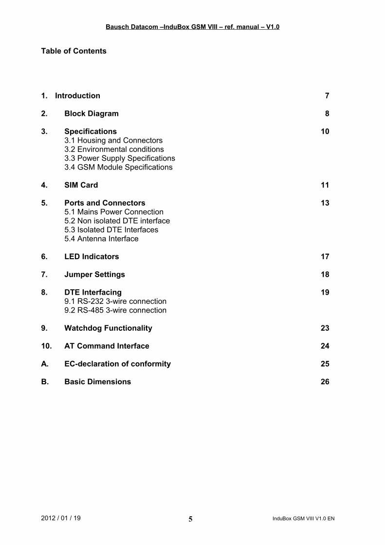
Table of Contents
1. Introduction 7
2. Block Diagram 8
3. Specifications 103.1 Housing and Connectors3.2 Environmental conditions3.3 Power Supply Specifications3.4 GSM Module Specifications
4. SIM Card 11
5. Ports and Connectors 135.1 Mains Power Connection5.2 Non isolated DTE interface5.3 Isolated DTE Interfaces5.4 Antenna Interface
6. LED Indicators 17
7. Jumper Settings 18
8. DTE Interfacing 199.1 RS-232 3-wire connection9.2 RS-485 3-wire connection
9. Watchdog Functionality 23
10. AT Command Interface 24
A. EC-declaration of conformity 25
B. Basic Dimensions 26
2012 / 01 / 19 InduBox GSM VIII V1.0 EN5
Bausch Datacom –InduBox GSM VIII – ref. manual – V1.0
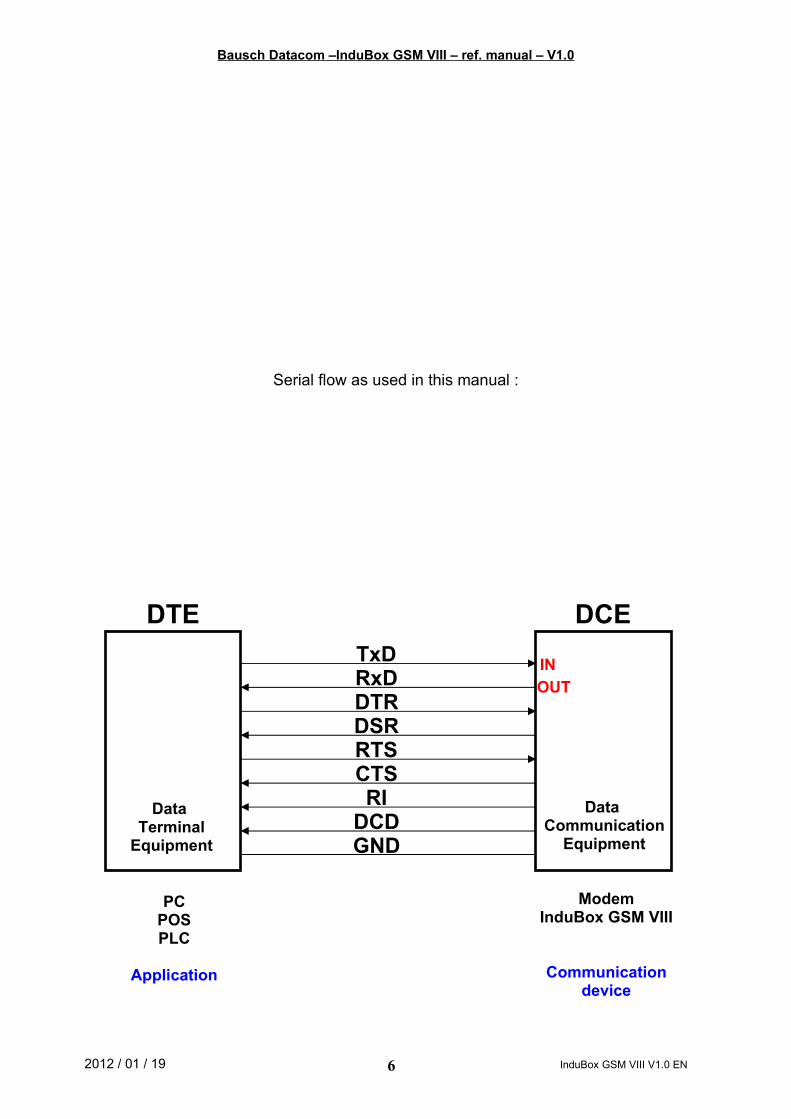
Serial flow as used in this manual :
2012 / 01 / 19 InduBox GSM VIII V1.0 EN6
DCEDTETxDRxDDTR
DCD
RTSCTSRI
DSR
GND
ModemInduBox GSM VIII
Communicationdevice
PCPOSPLC
Application
INOUT
Data Terminal
Equipment
Data Communication
Equipment

Bausch Datacom –InduBox GSM VIII – ref. manual – V1.0
1. Introduction
This manual is the reference when setting up the InduBox GSM VIII modem for your application. Because of the nature of this product and it's field of application, some degree of technical background knowledge regarding the application and data-communication is assumed.
The InduBox GSM VIII modem is a versatile communication device designed to provide a very flexible data communication solution for an industrial environment. The InduBox GSM VIII modem contains a number of options to accommodate different communication speeds, power supplies and interfaces.
The InduBox GSM VIII is designed to transmit and receive –transparent- ASCII formatted data on a GSM data channel. Communication between the InduBox GSM VIII and a DTE range from 300 to 115.200 bps. With the GPRS/UMTS option and embedded TCP/IP stack, data can be send/received into a TCP/UDP socket to and from a remote socket server.
Besides serial communication using standard RS-232, other galvanically and logically separated interfaces are available like RS-232 3-wire and RS-485 3-wire.
Besides a periodical (hard) reset, configurable between 1 and 168 hour, an external modem reset is possible via the additional 'V+'-connection to ensure a proper modem working.
The InduBox GSM VIII is designed in a robust housing with different power supply options accepting a wide range of AC voltages.
2012 / 01 / 19 InduBox GSM VIII V1.0 EN7

Bausch Datacom –InduBox GSM VIII – ref. manual – V1.0
2. Block Diagram
The block diagram below details the location and interconnection of the different functional units within the modem. The most important units are briefly described.
AC/DC power supply The mains supply (ac) must be connected to the InduBox GSM VIII modem via a 2 pin terminal block with screw contacts. Make sure the voltage supplied to the modem is in the range of the InduBox GSM VIII input voltage (see specifications for details on voltage range).
Long Term Watchdog A long term watchdog circuit is implemented. The modem will perform a reset each 1 to 168 hour (configurable) and/or if necessary via the external '+V'-connection to prevent a lock-up. The power supply of the GSM/GPRS module will be disconnected for a few seconds after the reset period. A ‘heartbeat’-LED is implemented to check the long term watchdog.
2012 / 01 / 19 InduBox GSM VIII V1.0 EN8

Bausch Datacom –InduBox GSM VIII – ref. manual – V1.0
Switched regulator To create the necessary dc-voltage (Vgsm) to power the GSM/GPRS module a 2A step down switching regulator is implemented.
Configuration InterfaceThe InduBox GSM VIII modem has one complete (TxD, RxD, DCD, DTR, RTS, CTS, RI and GND) RS-232 interface. This RS-232 interface is not isolated and must be used to configure and/or update the Sierra Wireless (Wavecom) GSM/GPRS module. This interface has a RJ-45 connector.
Isolated DTE interfaces The InduBox GSM VIII has 2 galvanically isolated serial interfaces :
3- wire RS-232 (RxD, TxD, GND’) :
This interface is connected (galvanically separated) to the internal configuration interface (RJ-45) the UART1 of the Q2686 GSM/GPRS module. Pin 4 can be used for external reset (V') or for powering (100 mA Imax) an external device (+5V'), selectable via resistor stuffing.
3- wire RS-485 (A, B, GND’) :
This interface is connected (galvanically separated) to the UART2 of the Q2686 GSM/GPRS module.
Pin 4 can be used for external reset (V') or for powering (100 mA Imax) an external device (+5V'), jumper selectable via JP2.
V.24 Status LED’s The V.24 lines to and from the UART1 GSM/GPRS module have a LED indicator.
GSM/GPRS module The InduBox GSM VIII has a built-in Sierra Wireless (Wavecom) Q2686 GSM/GPRS Quad band module. Different applications/configurations are possible with or without OpenAT firmware.
2012 / 01 / 19 InduBox GSM VIII V1.0 EN9

Bausch Datacom –InduBox GSM VIII – ref. manual – V1.0
Specifications
3.1 Housing and Connectors
• Housing: Bausch InduBox housingbottom enclosure and seal-able connector cover
ABS with self-extinguishing V0 additivetransparent cover
polycarbonate + self-extinguishing V1
dimensions with connector cover: 180 x 108 x 71 mmdimensions without connector cover: 145 x 108 x 71 mm
• Connectors: plug and connector pitch 5.08 mmmaximum wiring section 2.5 mm2
AMP 50 Ohm FME antenna connector
3.2 Environmental conditions
Temperature in use -25°C / + 55°CHumidity in use 10% - 75% (non condensing)
3.3 Power Supply Specifications
Input voltage range: 90 – 253 VacInput frequency: 47 – 63 HzPower: 6.3 VAidle 7.5 VAmax
3.5 Widle 4.5 Wmax
3.4 GSM-module Specifications
The InduBox GSM VIII modem uses a Sierra Wireless (Wavecom) Q2686 quad band GSM or GSM/GPRS module. Check the Sierra Wireless reference manual for detailed information.
2012 / 01 / 19 InduBox GSM VIII V1.0 EN10

Bausch Datacom –InduBox GSM VIII – ref. manual – V1.0
4. SIM Card
Disconnect the mains power before opening the InduBox GSM VIII modem!
Install a SIM card into the SIM card interface socket. Without a SIM card the InduBox GSM VIII will communicate with the DTE but will not respond properly on all commands.
Must applications are using a SIM card with disabled PIN code request !
The International Mobile Subscriber Identity (IMSI) is used for internal signaling and is saved on the SIM (processor card). If the SIM is removed from the terminal, any existing connections are cleared and further call setup is prevented with one exception: emergency calls.
Use the +WIMEI? command to view the IMEI code of the GSM module.
2012 / 01 / 19 InduBox GSM VIII V1.0 EN
Power Supply
GSM module
MAINS RS-232 RS-485
11

Bausch Datacom –InduBox GSM VIII – ref. manual – V1.0
How to install the SIM card:
1. Disconnect the mains power and DTE interface.2. Open the InduBox GSM VIII enclosure.3. The SIM cardholder is placed in the upper right corner onto the PCB.
4. Slide the upper part to the LEFT position.5. Rotate the SIM card holder upper part to the upright position. 6. Insert the SIM card into the upper part of the card holder.
7. Rotate back and close the upper part of the SIM cardholder8. Finally slide the upper part to the right (LOCK) position.
9. Close the InduBox GSM VIII enclosure.10. Connect mains power and DTE interface.
See the +CPIN command for more info about entering the PIN number.
2012 / 01 / 19 InduBox GSM VIII V1.0 EN12

Bausch Datacom –InduBox GSM VIII – ref. manual – V1.0
5. Ports and Connectors
Before you start the installation, take a moment to become more familiar with the possible connections to and from the InduBox GSM VIII modem.
The InduBox GSM VIII has three types of connectors; one internal RJ-45, three screw connectors with corresponding plugs and one FME connector.
Disconnect the mains power before connecting or disconnecting the power and/or DTE plugs !
5.1 Mains Power Connection
PIN1 L12 N
Always disconnect the mains power before connecting or disconnecting the power plug. Make sure the voltage supplied to the modem is in the range of the InduBox GSM VIII input voltage (see specifications for details on voltage range).
When the InduBox GSM VIII modem is connected via a standard mains plug, the used mains socket must be directly accessible and easy reachable.
2012 / 01 / 19 InduBox GSM VIII V1.0 EN13
RS-232Mains RS-485L11
N2
RxD1
TxD2
GND3
V+4
B1
A2
GND3
V+4
ANT

Bausch Datacom –InduBox GSM VIII – ref. manual – V1.0
5.2 Non isolated DTE Interface
Only devices which are conform with the safety regulations can be connected to the DTE port!
This interface is connected to the UART1 and must be used to configure and upload firmware to the GSM/GPRS module. This interface is accessible via a RJ-45 8-pin connector, is not galvanically isolated and has all standard V.24 interface lines. A RJ-45 to a standard female DB-9 connector cable is available.
PIN V.24 Description Direction Level1 DCD Data Carrier Detect DCE DTE V.28 2 RXD Receive Data DCE DTE V.283 TXD Transmit Data DTE DCE V.284 DTR Data Terminal Ready DTE DCE V.285 GND Ground - -6 RI Ring Indicator DCE DTE V.287 RTS Request to Send DTE DCE V.288 CTS Clear to Send DCE DTE V.28
2012 / 01 / 19 InduBox GSM VIII V1.0 EN
Power Supply
GSM module
MAINS RS-232 RS-485
14
Configuration InterfaceRJ-45 8 contacts
8 ………. 1
Bausch Datacom –InduBox GSM VIII – ref. manual – V1.0
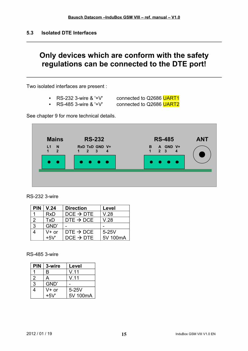
5.3 Isolated DTE Interfaces
Only devices which are conform with the safety regulations can be connected to the DTE port!
Two isolated interfaces are present :
• RS-232 3-wire & '+V' connected to Q2686 UART1• RS-485 3-wire & '+V' connected to Q2686 UART2
See chapter 9 for more technical details.
RS-232 3-wire
PIN V.24 Direction Level1 RxD DCE DTE V.282 TxD DTE DCE V.283 GND’ - -4 V+ or
+5V'DTE DCEDCE DTE
5-25V5V 100mA
RS-485 3-wire
PIN 3-wire Level1 B V.112 A V.113 GND’ -4 V+ or
+5V'5-25V5V 100mA
2012 / 01 / 19 InduBox GSM VIII V1.0 EN15
RS-232Mains RS-485L11
N2
RxD1
TxD2
GND3
V+4
B1
A2
GND3
V+4
ANT

Bausch Datacom –InduBox GSM VIII – ref. manual – V1.0
5.4 Antenna Interface
The GSM antenna must be connected directly on the GSM modem via a cable, depending on the application and the GSM RF field strength at the site. The antenna interface connector is FME (male).
Never use the InduBox GSM VIII modem without a proper antenna attached!
2012 / 01 / 19 InduBox GSM VIII V1.0 EN16

Bausch Datacom –InduBox GSM VIII – ref. manual – V1.0
6. LED Indicators
There are 10 LED’s located onto the InduBox GSM VIII modem printed circuit.
GSM yellow GSM Network service DCE ON not registered on the networkSlow flash (2 s. OFF) registered on the network Quick flash (600 ms OFF) communication in progress
TXD red Transmit Data DTE DCE Reflects the state of the TXD signalRXD red Receive Data DCE DTE Reflects the state of the RXD signalDTR red Data Terminal Ready DTE DCE Reflects the state of the DTR signalDCD red Data Carrier Detect DCE DTE Reflects the state of the DCD signalRI red Ring Indicator DCE DTE Reflects the state of the RI signal
MDE green OpenAT - Mode - Ref. OpenAT application description
WD green Watchdog “Tick” - Reflects the state of the WatchdogWD red ON during reset cycle -
5 V’ green Isolated 5Vdc power supply
- OFF : no voltage presentON : voltage present
2012 / 01 / 19 InduBox GSM VIII V1.0 EN17
5V’
RXD
TXD
DCD
DTR
RI
GSM
WD
WD
Power Supply
GSM module
MAINS RS-232 RS-485
MDE

Bausch Datacom –InduBox GSM VIII – ref. manual – V1.0
7 . Jumper Settings
The InduBox GSM VIII modem has 4 jumpers. The functions of the jumpers will be described in the paragraphs below.
JP6 openclosed
GSM module normal operation (default)GSM module BOOT operation
JP2 1 2 (down) closed3 2 (up) closed
RS-485 – pin 4 connected to +5V'RS-485 – pin 4 connected to V+
JP1 OpenClosed
no 120 ohm termination between A and B120 ohm termination between A and B
JP3 OpenClosed
20 ms delay <9600 bps2 ms delay >9600 bps
2012 / 01 / 19 InduBox GSM VIII V1.0 EN18
Power Supply
GSM module
MAINS RS-232 RS-485
JP2 JP1
JP3
JP6

Bausch Datacom –InduBox GSM VIII – ref. manual – V1.0
8 . DTE Interfacing
The InduBox GSM VIII modem has three different DTE interfacing possibilities. A RS-232 3-wire and a RS-485 3-wire interface are parallel connected onto the V.24-bus.
Configuration and setup is described in the paragraphs below.
Disconnect the mains power before opening the InduBox GSM VIII modem!
The isolated interfaces are galvanically separated from the main functions of the InduBox GSM VIII ; RxD and TxD are separated via an OptoCoupler, a second 5 Vdc power supply is created via an aditional DC/DC convertor.
2012 / 01 / 19 InduBox GSM VIII V1.0 EN19
UART1/2
RJ-45 8-pin connectorStandard RS-232
3-pin header/plug with screw contactsRS-232 3-wire
5V
RS-232
RS-4852
5V’
TxD
RxD
DCD / RxD / TxD / DTR / RI / RTS / CTS
3-pin header/plug with screw contactsRS-485 3-wire

Bausch Datacom –InduBox GSM VIII – ref. manual – V1.0
8.1 RS-232 3-wire connection
8.1.1 Connection
PIN V.24 Direction Level1 RxD DCE DTE V.282 TxD DTE DCE V.283 GND’ - -4 V+
+5V'DTE DCEDCE DTE
5-25V5V 100mA
8.1.2 Schematic
8.1.3 Hardware Configuration
There are no specific jumpers to enable or disable the RS-232 3-wire interface.
8.1.4 Software Configuration
This interface is full duplex and can be used on all possible baudrates up to 115200 bps. This interface uses only RxD and TxD. DTR and RTS are not used, thus inactive. Be sure to disable those signals in the configuration of the InduBox GSM VIII ;
at+ifc=0,0 no RTS/CTS flow controlat&d0 no DTR signal present
2012 / 01 / 19 InduBox GSM VIII V1.0 EN20
RS-232Mains RS-485L11
N2
RxD1
TxD2
GND3
V+4
B1
A2
GND3
V+4
ANT
UART1
5V5V’
TxD
RxD
5V’
1. RXD2. TXD3. GND’4. +
TTL/V.10LevelShift

Bausch Datacom –InduBox GSM VIII – ref. manual – V1.0
8.2 RS-485 3-wire connection
8.2.1 Connection
PIN 3-wire Level1 B V.112 A V.113 GND’ -4 V+
+5V'5-25V5V 100mA
8.2.2 Schematic
2012 / 01 / 19 InduBox GSM VIII V1.0 EN21
RS-232Mains RS-485L11
N2
RxD1
TxD2
GND3
V+4
B1
A2
GND3
V+4
ANT
UART2
RxD
TxDA
B
dT
receiver
transmitter
~recENtraEN
120 E
JP3
JP1
UART2
5V’
1234
RxD
TxD
Open - 20 ms - < 9600 bpsClose - 2 ms - >= 9600 bps
5V’
560 E
560 E

Bausch Datacom –InduBox GSM VIII – ref. manual – V1.0
8.2.3 Hardware Configuration
The following jumpers must be set for RS-485 :
JP1 open no 120 ohm termination between A and Bclosed 120 ohm termination between A and B
JP3 open 20 ms delay <9600 bpsclosed 2 ms delay >=9600 bps
8.2.4 Software Configuration
This interface is half duplex and can be used from 300 to 115200 bps. This interface uses only RxD and TxD. DTR and RTS are not used, thus inactive. Be sure to disable those signals in the configuration of the InduBox GSM VIII ;
at+ifc=0,0 no RTS/CTS flow controlat&d0 no DTR signal present
RxD and TxD info is transmitted onto the same 2 wires. To avoid a double echo during command mode, the modem echo should be disabled ;
ate0 disable modem echo
2012 / 01 / 19 InduBox GSM VIII V1.0 EN22

Bausch Datacom –InduBox GSM VIII – ref. manual – V1.0
9. Watchdog Functionality
To prevent a “total lock-up” of the InduBox GSM VIII a long term watchdog is implemented. This function is created with a separate micro-controller. The micro-controller itself is guarded with it’s own internal watchdog (+/- 1 second refresh / LED flash).
This long term watchdog has 2 possible ways to reset the modem :1. configurable periodically reset2. external reset triggered by the '+V'-connection
9.1 Periodically reset
The power supply will be disconnected, after a controlled and proper GSM disconnection, during 20 seconds after the selected reset period IF the modem is NOT connected (inactive DCD signal).
If the reset period is ended and the modem is connected to a remote host (active DCD signal) the reset will not be conducted. If the reset period is ended + 10 minutes and the watchdog already past a reset, because of an active DCD signal, the reset will be conducted! Otherwise, the InduBox GSM VIII can be “locked-up” with an active DCD signal the watchdog will never be able to reset the WAN module.
Time is programmable via the serial setup menu of the modem.This menu is accessible via the RJ-45 serial interface (9600 bps 8N1) after hitting the blue push 'switch' located next to the reset processor onto the modem printed circuit board.
| -- START --|| Bausch Datacom InduBox GSM VIII setup [V1.0]|| Reset period time select [currently 24 hour]| Do you want to change this [y/n] :
Enter 'y' if you want to change the default 24 hour to another value.The new value will automatically be stored in non volatile RAM.
9.2 External reset
The power supply will be disconnected, after a controlled and proper GSM disconnection, during 20 seconds when a negative slope (5-25V to 0V) is detected on the '+V'-input.
There is no DCD check done in this reset mode.
2012 / 01 / 19 InduBox GSM VIII V1.0 EN23

Bausch Datacom –InduBox GSM VIII – ref. manual – V1.0
10. AT Command Interface
More information about the commands to the InduBox GSM VIII modem, and the responses from the InduBox GSM VIII modem, are described in the Sierra Wireless (Wavecom) reference manual ‘AT commands interface guide’.
2012 / 01 / 19 InduBox GSM VIII V1.0 EN24

Bausch Datacom –InduBox GSM VIII – ref. manual – V1.0
A. EC-Declaration of conformity
CE / EMCTST25-3 (additional extended immunity tests)
EN61000-3-2 Electromagnetic compatibility, part 3, section 2Limits for harmonic current emissions.
EN61000-3-3 Electromagnetic compatibility, part 3, section 3Limitations of voltage fluctuation and flicker.
EN61000-4-2 Electromagnetic compatibility, part 4, section 2Electrostatic discharge immunity test.
CISPR24 levels : 4 KV contact / 8 KV air --> 8 KV contact / 15 KV air
EN61000-4-3 Electromagnetic compatibility, part 4, section 3Radiated fields immunity test.CISPR24 levels : 3 V/m 80 MHz - 1000 Mhz, mod. AM 80% 1KHz --> 10 V/m
EN61000-4-4 Electromagnetic compatibility, part 4, section 4Electrical fast transient/burst immunity test.CISPR24 levels : 0.5 KV +/- 50 V and 1 KV +/- 10 V on AC mains--> 2 KV and 4 KV
EN61000-4-5 Electromagnetic compatibility, part 4, section 5Surge immunity test.CISPR24 levels : 0.5 KV +/- 50 V and 1 KV +/- 10 V on AC mains--> 2 KV (4KV and 6 KV)
EN61000-4-6 Electromagnetic compatibility, part 4, section 6Conducted immunity test.CISPR24 levels : 3 V 0.15 MHz - 80 MHz, mod. 80% at 1 KHz--> 10 V
EN61000-4-8 Electromagnetic compatibility, part 4, section 8Power frequency magnetic field immunity test.CISPR24 levels
EN61000-4-11 Electromagnetic compatibility, part 4, section 11Voltage dips, short interruptions and voltage variations immunity
test.CISPR24 levels
ENV50204 Electromagnetic compatibility, Basic immunity standard, RadiatedElectromagnetic field from digital radio telephones immunity test.CISPR24 levels : 3 V/m 890-1000 MHz / 1700-2000 MHz, mod.
100% 200Hz--> 10 V/m (30 V/m) on 890 - 1000 MHz
EN55022 (1994)+A1(1995)+A2(1997) Limits and methods of measurement of radio-disturbance characteristics of ITE-equipment.EN55022 class B limitsRadiated emission : 30 - 1000 MHzconducted emission : 0.15 - 30 MHz
EN55024 performance criteria for immunity testsEN61000-6-3 performance criteria for emission tests
2012 / 01 / 19 InduBox GSM VIII V1.0 EN25

Bausch Datacom –InduBox GSM VIII – ref. manual – V1.0
B. InduBox Dimensions
2012 / 01 / 19 InduBox GSM VIII V1.0 EN26

Bausch Datacom –InduBox GSM VIII – ref. manual – V1.0
2012 / 01 / 19 InduBox GSM VIII V1.0 EN27

Bausch Datacom –InduBox GSM VIII – ref. manual – V1.0
2012 / 01 / 19 InduBox GSM VIII V1.0 EN28

Bausch Datacom –InduBox GSM VIII – ref. manual – V1.0
2012 / 01 / 19 InduBox GSM VIII V1.0 EN29


![SPECIFICATION & INSTALLATION GUIDE52 gsm to 450 gsm (Plain, Fine, Color Specific, Coated-G, Coated-M) 81 gsm to 350 gsm (Textured) 70 gsm to 100 gsm (Envelopes) ... Envelope Seam [1]](https://img.pdfslide.us/doc/110x75/5ebee13946efcd7097328efd/specification-installation-52-gsm-to-450-gsm-plain-fine-color-specific.jpg)