Embed Size (px)
Citation preview
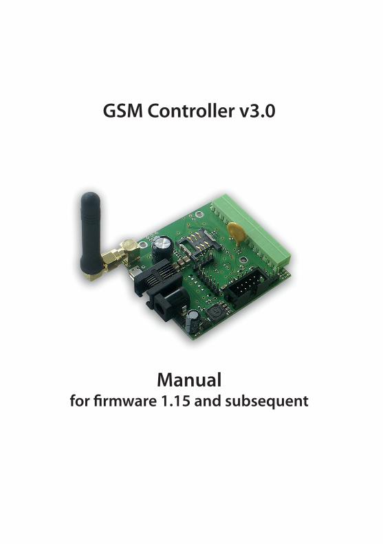
GSM Controller v3.0
Manualfor firmware 1.15 and subsequent
2
manual GSM Controller v3.0 – GSMKON-030
www.tinycontrol.eu
GSM ControllerGSM v3 controller allow monitor by gsm network different phisical parameters and con-trol remotely on/off 5 outputs. Control is done through SMS messages and monitoring can be run by SMS or gprs data transmission to internet server. Http datas can be sent for example to www.thingspeak.com server, where are not only collected but can be read as dynamically presented graphs. Further GSM controller functionality is action automating. After simple set up when some input parameters reach the set size, outputs actions will be performed, eg send a message or switching outputs.
ExamplesISP•control power supply - notification of his disappearance •reserve battery voltage control •temperature control or the presence of people in the server and I reaction
Home automation•automatic control of the radiator and notification of status or temperature •control on / off lighting or other devices remotely or by part program •simple alarm system notification
Fittings•temperature control and possible notification, switching valve, etc. •monitoring of voltage and possibly automatic switching to source spare
Monitoring for Environment and agriculture•collection of environmental data with the extensive grounds •the meteorological monitoring
manual GSM Controller v3.0 – GSMKON-030
3www.tinycontrol.eu
RESTARTER, MONITOR, WATCHDOG, CONTROLLERBASIC POSSIBILITIES:•management by SMS or USB (after connecting to computer),•monitoring by gprs transmission to http server, by SMS received on user phone or by USB,•upgrade new firmware by USB port•monitoring logic states, for example move sensors, position detectors•measurment of voltage, temperature, humidity i and many more by analog voltage
inputs•pulse counting on INP4D•transistor output (up to 1A), possibility to connect additinal board with 4 realys or PoE
injector with power switching•SMS or http notification about logical inputs•supported sensors: PT1000, DS18B20, DHT22 (temperature and humidity)•up to 99 phone numbers in memory allowing to controll - solution for gate opener
in restricted areas•command authentication by password•remote power supply measurement.
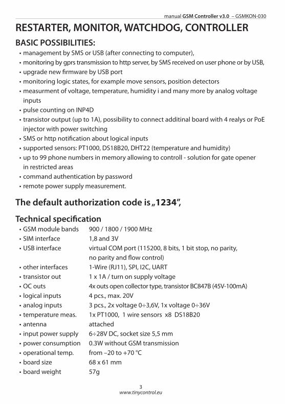
The default authorization code is „1234”,
Technical specification•GSM module bands 900 / 1800 / 1900 MHz•SIM interface 1,8 and 3V•USB interface virtual COM port (115200, 8 bits, 1 bit stop, no parity,
no parity and flow control)•other interfaces 1-Wire (RJ11), SPI, I2C, UART•transistor out 1 x 1A / turn on supply voltage•OC outs 4x outs open collector type, transistor BC847B (45V-100mA)• logical inputs 4 pcs., max. 20V•analog inputs 3 pcs., 2x voltage 0÷3,6V, 1x voltage 0÷36V•temperature meas. 1x PT1000, 1 wire sensors x8 DS18B20•antenna attached• input power supply 6÷28V DC, socket size 5,5 mm•power consumption 0.3W without GSM transmission•operational temp. from –20 to +70 °C•board size 68 x 61 mm•board weight 57g
4
manual GSM Controller v3.0 – GSMKON-030
www.tinycontrol.eu
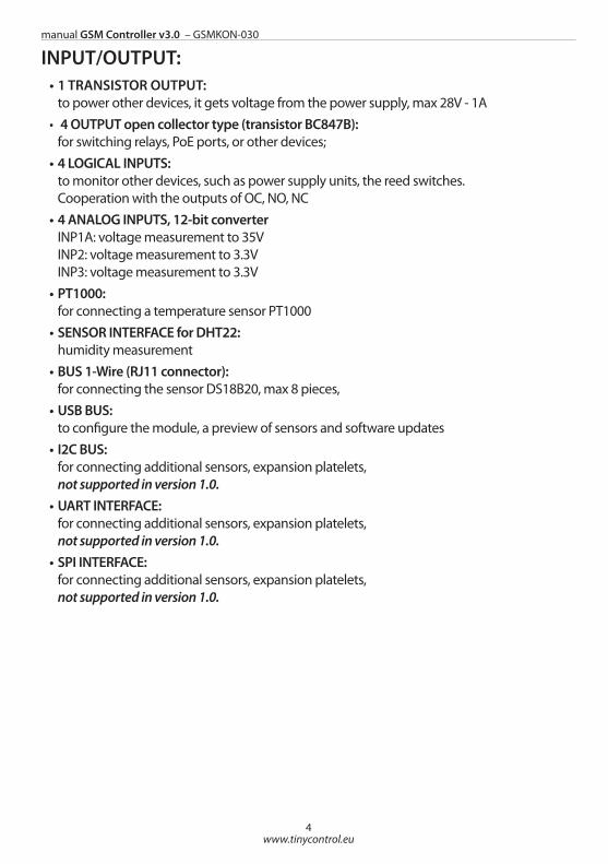
INPUT/OUTPUT:•1 TRANSISTOR OUTPUT:
to power other devices, it gets voltage from the power supply, max 28V - 1A• 4 OUTPUT open collector type (transistor BC847B):
for switching relays, PoE ports, or other devices;•4 LOGICAL INPUTS:
to monitor other devices, such as power supply units, the reed switches. Cooperation with the outputs of OC, NO, NC
•4 ANALOG INPUTS, 12-bit converter INP1A: voltage measurement to 35V INP2: voltage measurement to 3.3V INP3: voltage measurement to 3.3V
•PT1000: for connecting a temperature sensor PT1000
•SENSOR INTERFACE for DHT22: humidity measurement
•BUS 1-Wire (RJ11 connector): for connecting the sensor DS18B20, max 8 pieces,
•USB BUS: to configure the module, a preview of sensors and software updates
•I2C BUS: for connecting additional sensors, expansion platelets, not supported in version 1.0.
•UART INTERFACE: for connecting additional sensors, expansion platelets, not supported in version 1.0.
•SPI INTERFACE: for connecting additional sensors, expansion platelets, not supported in version 1.0.
manual GSM Controller v3.0 – GSMKON-030
5www.tinycontrol.eu
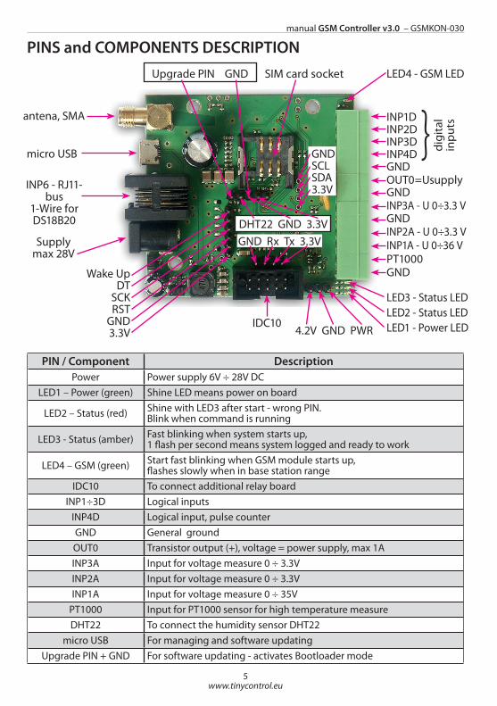
PINS and COMPONENTS DESCRIPTION
PIN / Component DescriptionPower Power supply 6V ÷ 28V DC
LED1 – Power (green) Shine LED means power on board
LED2 – Status (red) Shine with LED3 after start - wrong PIN.Blink when command is running
LED3 - Status (amber) Fast blinking when system starts up,1 flash per second means system logged and ready to work
LED4 – GSM (green) Start fast blinking when GSM module starts up,flashes slowly when in base station range
IDC10 To connect additional relay boardINP1÷3D Logical inputs
INP4D Logical input, pulse counterGND General groundOUT0 Transistor output (+), voltage = power supply, max 1AINP3A Input for voltage measure 0 ÷ 3.3V INP2A Input for voltage measure 0 ÷ 3.3VINP1A Input for voltage measure 0 ÷ 35V
PT1000 Input for PT1000 sensor for high temperature measureDHT22 To connect the humidity sensor DHT22
micro USB For managing and software updatingUpgrade PIN + GND For software updating - activates Bootloader mode
antena, SMA
Upgrade PIN GND
INP3DINP4DGNDOUT0=UsupplyGNDINP3A - U 0÷3.3 VGNDINP2A - U 0÷3.3 VINP1A - U 0÷36 VPT1000GND
Supplymax 28V
LED4 - GSM LED
LED1 - Power LED
INP6 - RJ11- bus
1-Wire for DS18B20
GNDSCLSDA3.3V
Wake UpDT
SCKRST
GND3.3V
INP1DINP2D
SIM card socket
IDC10
micro USB digi
tal
inpu
ts}
LED2 - Status LEDLED3 - Status LED
DHT22 GND 3.3VGND Rx Tx 3.3V
4.2V GND PWR
6
manual GSM Controller v3.0 – GSMKON-030
www.tinycontrol.eu
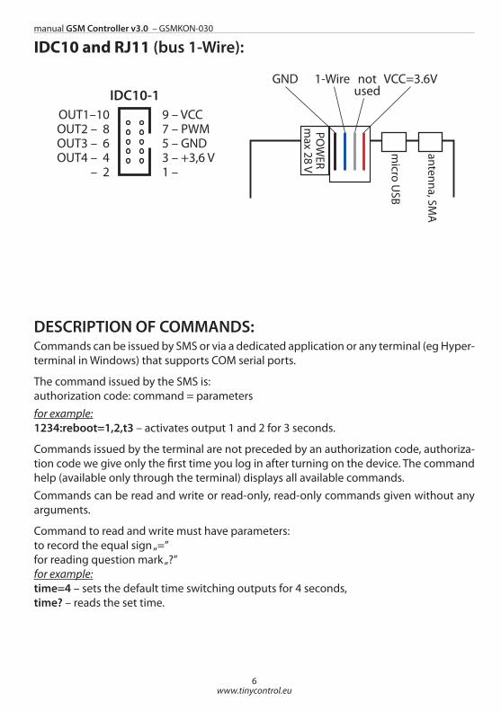
IDC10 and RJ11 (bus 1-Wire):
DESCRIPTION OF COMMANDS:Commands can be issued by SMS or via a dedicated application or any terminal (eg Hyper-terminal in Windows) that supports COM serial ports.
The command issued by the SMS is: authorization code: command = parametersfor example:1234:reboot=1,2,t3 – activates output 1 and 2 for 3 seconds.
Commands issued by the terminal are not preceded by an authorization code, authoriza-tion code we give only the first time you log in after turning on the device. The command help (available only through the terminal) displays all available commands.Commands can be read and write or read-only, read-only commands given without any arguments.
Command to read and write must have parameters:to record the equal sign „=”for reading question mark „?”for example:time=4 – sets the default time switching outputs for 4 seconds,time? – reads the set time.
micro U
SB
antenna, SMA
POW
ERm
ax 28 V
notused
GND 1-Wire VCC=3.6VIDC10-1
9 – VCC7 – PWM5 – GND3 – +3,6 V1 –
OUT1–10OUT2 – 8OUT3 – 6OUT4 – 4
– 2
IDC10-29 – VCC7 – INP45 – GND3 – +3,6 V1 – DHT22
INP5 –10– 8
PWM2 – 6PWM3 – 4PWM1 – 2
manual GSM Controller v3.0 – GSMKON-030
7www.tinycontrol.eu
LIST OF COMMANDS:1. reboot – activates certain output / output for the specified timeExamples: reboot=3,4 – will switch outputs 3 and 4 to the default time set by the command "time";reboot=1,0,3,t34 – activates output 1, 0 (transistor output), 3 at time 34 seconds;reboot? – reads the current state of the outputs, to check whether switching time set has already elapsed
2. on – output activatesExamples:on=1,2,3,4,0 – turns on all outputson=0 – activates only output 0 (transistor)
3. off – output switched offExamples:off=1,2 – off output 1 and 2
4. time – sets the default output switching, as we spend reboot command without a pa-rameter t
5. code – sets the authorization code, by default 4 digit code 1234; 6. pin – set a 4-digit PIN on your SIM card, if the card requires a pin. You need to set the pin as a set card. NOTE: The command does not change the pin on the card itself
7. inpd – reads the state of the digital inputs (logic), read-only command8. outs – reads the current state of the outputs, the command read-only
9. number – sets one of the 100 telephone number that will be able to execute when you call on the device. Up to 12 digits. In addition to the first four numbers (from position 1 to 4) will also be sent SMS messages (if enabled monitoring logic inputs) in the case of changes in the inputs. The number of phone numbers (1 to 4) which will be sent SMS, define com-mand acnumber.Examples:number=1:666777888 – sets the phone number for the first positionnumber?1 – reads the number of the first position
10. acnumber – sets the number of active phone numbers for SMS alerts
11. call – sets the function called when dialing deviceExamples:call=reboot=1,2,t3 – when dialing reboot function will be called with parameters as given
12. remouts – enter the value of 1 causes the output states when remembering switched on again
13. uptime – shows the amount of time elapsed since the inclusion of the device, read--only command
8
manual GSM Controller v3.0 – GSMKON-030
www.tinycontrol.eu
14. name – sets the name of the device, max. 32 charactersExamples:name=home device
15. upgrade – runs the bootloader mode to update the software, flash simultaneously LED2 and LED3, to update special software is needed, the command without parameters
16. desinpd – content of the notifications sent when changing the state of the logic inputsExamples:desinpd=1:0:test content – sets the content for INP1D, sent the high state on this inputdesinpd=1:1:content test2 – sets the content for INP1D, sent the low state at this inputdesinpd?1 – reads the setting content for INP1Ddesinpd=2:0:test content – sets the content for INP2D, sent the high state on this input
17. desanalog – content of the notifications for the analog inputs, the numbers are: 1–VIN,2–PT10003–INP1A,4–INP2A,5–INP3AThe software 1.0 notifications only come to the VIN (supply voltage) Examples:desanalog=1:0:test content – sets the content of the VIN (voltage), if exceeded more than setdesanalog=1:1:test content2 – sets the content of the VIN (voltage) if it is dropped below the setdesanalog=2:0:test content – sets the content for the PT1000, if exceeded more than set
18. monitoron – enables monitoring of the selected logic inputExamples:monitoron=1,2,3,4 – enables monitoring of all four inputsmonitoron=1 – enables monitoring only INP1D if the previous were previously on, it is necessary to disable the command monitoroffmonitoron? – verify that the inputs are included to monitoring
19. monitoroff – disables the monitoring logic inputsExamples:monitoroff=1,2 – off input monitoring INP1D and INP2D, will not be a notifications in changed states of these inputs
20. version – shows the current versions of the hardware (HW) and software (SW), read--only command
21. adcprint – displays the status of each input every 2 seconds, the command works only in the terminalExamples:adcprint=1 – automatically displays the values of VIN, PT1000, INP1A, INP2A, INP3A, DHTT (DHT temperature), DHTH (DHT humidity) for the voltage to obtain a result in volts value
manual GSM Controller v3.0 – GSMKON-030
9www.tinycontrol.eu
must be divided by 100, for PT1000 and DHT divided by 10.adcprint=2 – displays the values directly (without any conversion to a voltage as above) with 12-bit converter for analog inputs VIN, PT1000, INP1A, INP2A, INP3A, values can vary from 0 to 4096, depending on the size of the measured voltage, eg for INP1A - for 0 volts will be set to 0, the 35V will be similar to 4096, for INP2A and INP3A, for 0 volts is 0 for 3.3V will be close to 4096.adcprint=3 – displays the values of the sensors DS18B20, the result must be divided by 10adcprint=0 – disables the display of the above-mentioned values
22. confirm – value of 1 enables sending return SMS after commands: reboot, on, off
23. vinread – reads the value of VIN (the supply voltage), read-only command24. ptread – reads the value of PT1000, read-only command,
25. inp1aread – reads the value of INP1A, read-only command26. inp2aread – reads the value of INP2A, read-only command27. inp3aread – reads the value of INP3A, read-only command
28. dthtread – reads the value of the temperature DHT sensor, a read-only command
29. dthhread – reads the value of the humidity DHT sensor, a read-only command
30. dsread – reads the value of 8 sensors DS18B20, read-only command31. vinset – sets the voltage at which, if exceeded / decrease will be sent SMSExamples:vinset=12,34 – sets the value of the 12.34Vvinset? – reads the set value
32. vinhis – sets the hysteresis for the above set voltageExamples:vinhis=0,80 – histereza ±0,80V
33. gprsapn – sets the apn, username and password for GPRSExamples:gprsapn=”internet”,”user”,”paswd” – enter values as in the example of quotes, below an example of how to set a blank password and usergprsapn=”internet”,””,””
34. gprsstart – GPRS starts, you do not have to run like we want to send data to the server via HTTP
35. gprsstop – stops GPRS
35. httpver – sets the http client versionExamples:httpver=1 – sets the http client versions 1.1httpver=0 – sets the http client versions 1.0
10
manual GSM Controller v3.0 – GSMKON-030
www.tinycontrol.eu
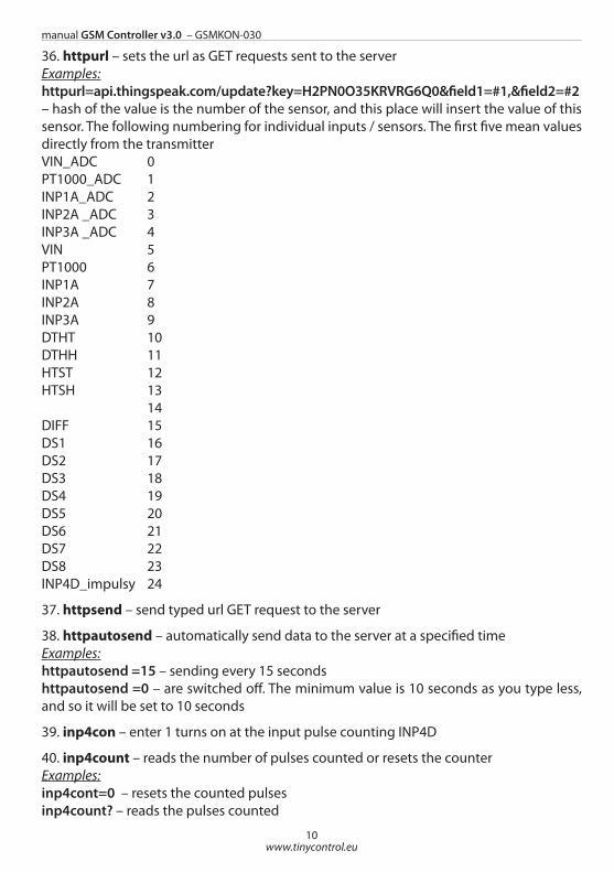
36. httpurl – sets the url as GET requests sent to the serverExamples:httpurl=api.thingspeak.com/update?key=H2PN0O35KRVRG6Q0&field1=#1,&field2=#2– hash of the value is the number of the sensor, and this place will insert the value of this sensor. The following numbering for individual inputs / sensors. The first five mean values directly from the transmitterVIN_ADC 0PT1000_ADC 1INP1A_ADC 2INP2A _ADC 3INP3A _ADC 4VIN 5PT1000 6INP1A 7INP2A 8INP3A 9DTHT 10DTHH 11HTST 12HTSH 13 14DIFF 15DS1 16DS2 17DS3 18DS4 19DS5 20DS6 21DS7 22DS8 23INP4D_impulsy 24
37. httpsend – send typed url GET request to the server
38. httpautosend – automatically send data to the server at a specified timeExamples:httpautosend =15 – sending every 15 secondshttpautosend =0 – are switched off. The minimum value is 10 seconds as you type less, and so it will be set to 10 seconds
39. inp4con – enter 1 turns on at the input pulse counting INP4D
40. inp4count – reads the number of pulses counted or resets the counterExamples:inp4cont=0 – resets the counted pulsesinp4count? – reads the pulses counted
manual GSM Controller v3.0 – GSMKON-030
11www.tinycontrol.eu
41. cusd – sending short codesExamples:cusd=*100# – shows the status of the account on the GSM operator (PLUS (PL))
42. signal – reads the GSM signal strength
43. upinpd – determines the logic input activates the state of highExamples:upinpd=1,3 – INP1D input and INP3D activated state of highupinpd? – reads the settings
44. downinpd – determines the logic input activates the low statusExamples:downinpd=1,3 – INP1D input and INP3D activated by the low status
45. restart – reboot the device
46. settingsreset – enter 1 to restart the settings stored in the memory to default, reset occurs when you turn on the device, as you enter a value of 0 before re-run the device will not reset
47. help – displays all the commands
12
manual GSM Controller v3.0 – GSMKON-030
www.tinycontrol.eu
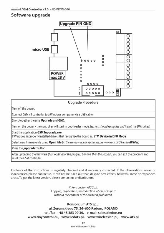
Software upgrade
Contents of the instructions is regularly checked and if necessary corrected. If the observations errors or inaccuracies, please contact us. It can not be ruled out that, despite best efforts, however, some discrepancies arose. To get the latest version, please contact us or distributors.
© Konsorcjum ATS Sp.J.Copying, duplication, reproduction whole or in part
without the consent of the owner is prohibited.
Konsorcjum ATS Sp.J.ul. Żeromskiego 75, 26–600 Radom, POLAND
tel./fax: +48 48 383 00 30, e-mail: [email protected], www.ledats.pl, www.wirelesslan.pl, www.ats.pl
micro USB
POWERmax 28 V
21
Upgrade PIN GND
Upgrade Procedure
Turn off the power.
Connect GSM v3 controller to a Windows computer via a USB cable.
Short together the pins Upgrade and GND.
Turn on the power - the controller will start in bootloader mode. (system should recognize and install the DFU driver)
Start the application GSM3upgrade.exe If Windows is properly installed drivers that recognize the board as: STM Device in DFU Mode
Select new firmware file using Open File (in the window opening change preview from DFU files to All files)
Press the „upgrade” button
After uploading the firmware (first waiting for the progress bar one, then the second), you can exit the program and reset the GSM controller.