Embed Size (px)
Citation preview
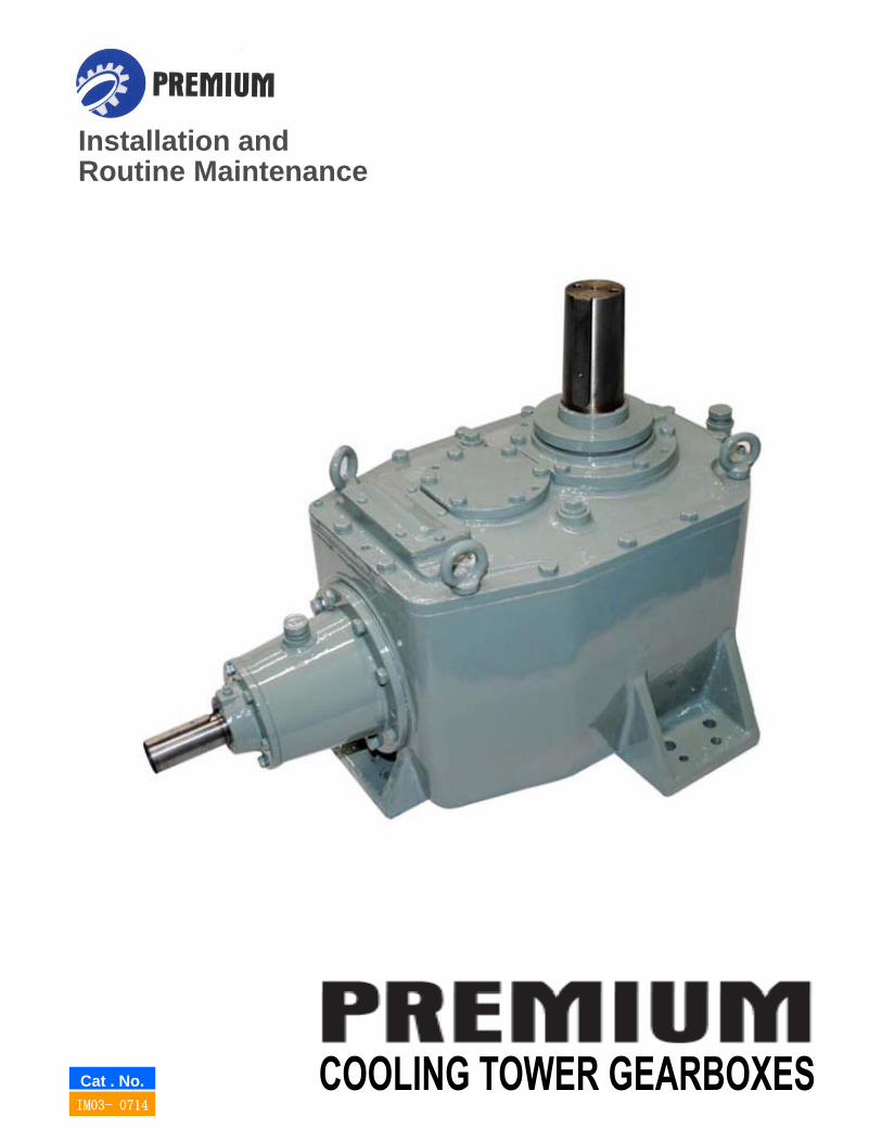
Installation andInstallation andRoutine Maintenance
Cat . No.IM03- 0714
INTRODUCTION
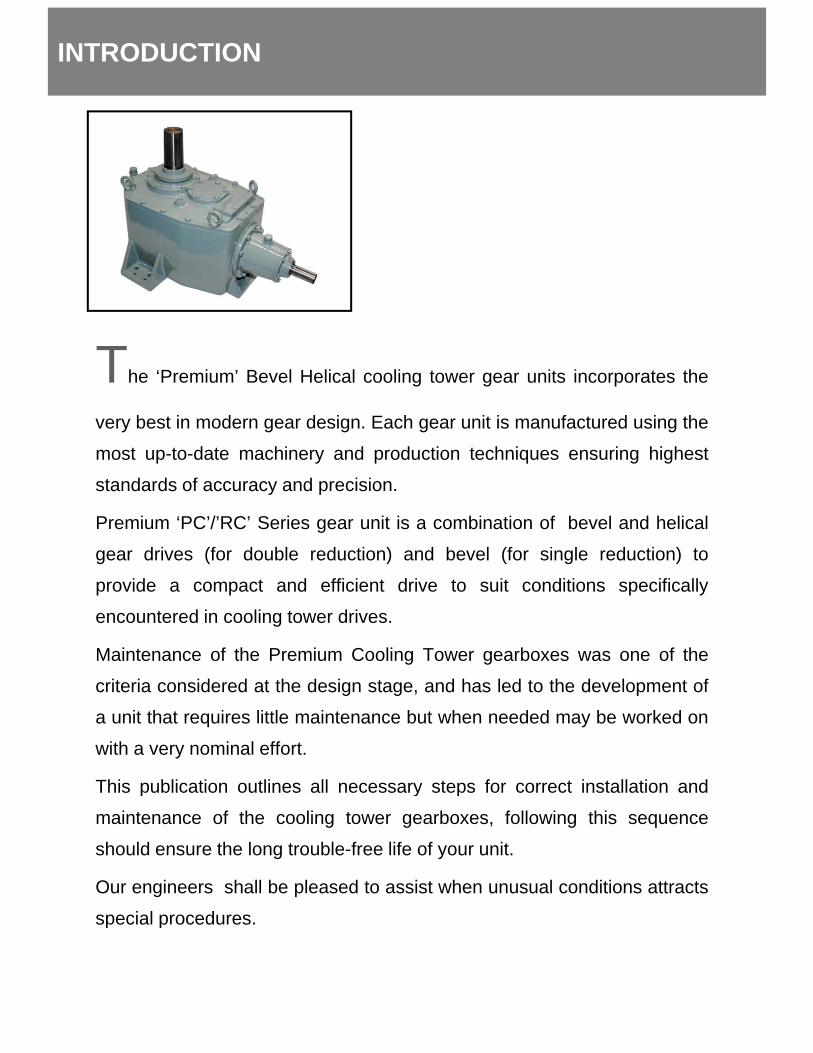
The ‘Premium’ Bevel Helical cooling tower gear units incorporates the
very best in modern gear design. Each gear unit is manufactured using the
most up-to-date machinery and production techniques ensuring highest
standards of accuracy and precision.
Premium ‘PC’/’RC’ Series gear unit is a combination of bevel and helicalPremium PC / RC Series gear unit is a combination of bevel and helical
gear drives (for double reduction) and bevel (for single reduction) to
provide a compact and efficient drive to suit conditions specifically
encountered in cooling tower drives.
Maintenance of the Premium Cooling Tower gearboxes was one of theMaintenance of the Premium Cooling Tower gearboxes was one of the
criteria considered at the design stage, and has led to the development of
a unit that requires little maintenance but when needed may be worked on
with a very nominal effort.
This publication outlines all necessary steps for correct installation andThis publication outlines all necessary steps for correct installation and
maintenance of the cooling tower gearboxes, following this sequence
should ensure the long trouble-free life of your unit.
Our engineers shall be pleased to assist when unusual conditions attracts
special proceduresspecial procedures.
UNIT IDENTIFICATION
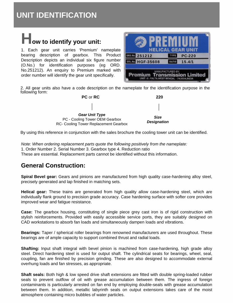
H t id tif itHow to identify your unit:1. Each gear unit carries ‘Premium’ nameplatebearing description of gearbox. This ProductDescription depicts an individual six figure number(O.No.) for identification purposes (eg ORD.No.251212). An enquiry to Premium marked withorder number will identify the gear unit specifically.
251212HGF-35608
PC-22015.4/1
2. All gear units also have a code description on the nameplate for the identification purpose in thefollowing form:
PC or RC 220
Gear Unit Type
y g p y
By using this reference in conjunction with the sales brochure the cooling tower unit can be identified.
Note: When ordering replacement parts quote the following positively from the nameplate:1. Order Number 2. Serial Number 3. Gearbox type 4. Reduction ratio
Gear Unit TypePC - Cooling Tower OEM Gearbox
RC- Cooling Tower Replacement Gearbox
SizeDesignation
These are essential. Replacement parts cannot be identified without this information.
General Construction:Spiral Bevel gear: Gears and pinions are manufactured from high quality case-hardening alloy steel,precisely generated and lap finished in matching sets.
Helical gear: These trains are generated from high quality allow case-hardening steel, which areindividually flank ground to precision grade accuracy. Case hardening surface with softer core providesimproved wear and fatigue resistance.
Case: The gearbox housing, constituting of single piece grey cast iron is of rigid construction withstylish reinforcements. Provided with easily accessible service ports, they are suitably designed onCAD workstations to absorb fan loads and simultaneously dampen loads and vibrations.
Bearings: Taper / spherical roller bearings from renowned manufacturers are used throughout. Thesebearings are of ample capacity to support combined thrust and radial loads.
Shafting: Input shaft integral with bevel pinion is machined from case-hardening, high grade alloysteel. Direct hardening steel is used for output shaft. The cylindrical seats for bearings, wheel, seal,coupling, fan are finished by precision grinding. These are also designed to accommodate externaloverhung loads and fan stresses as appropriateoverhung loads and fan stresses, as appropriate.
Shaft seals: Both high & low speed drive shaft extensions are fitted with double spring-loaded rubberseals to prevent outflow of oil with grease accumulation between them. The ingress of foreigncontaminants is particularly arrested on fan end by employing double-seals with grease accumulationbetween them. In addition, metallic labyrinth seals on output extensions takes care of the moistatmosphere containing micro bubbles of water particles.
P t ti f U it
STORAGE
Protection of Unit:All units prior to dispatch are test run with a rust preventive oil giving adequate protection to internalparts for a period of six months covering normal transport inland and overseas and coverage storage.When the unit is installed, the rust preventative dissolves in the first fill of lubricant without harmfuleffect. Shaft extensions are protected with a rust inhibitor which is proof against sea water and suitablefor under-cover storage upto 12 months.
Detailed procedure for storage and preservation for more than six months is mentioned on theinstruction plate mounted on top of the gear unit.
1. Ensure proper storage of the gear unit tocompletely protect it from direct sunlight,water and moisture.
2. Fill the gear unit completely with oil tillinstallation and commissioning
INSTALLATION
installation and commissioning.3. If commissioned but not in use, operate the
gear unit for a short time every two weeksor earlier.
INSTALLATION
Installation :1. Clean ventilator and rust preventive from shaft extension.2. Secure unit to a rigid foundation using HD bolts to GR8.8 Specification minimum.g g p3. Align unit with the drive shaft. For better performance use of Composite/Carbon fiber drive shaft is
recommended.4. Install drive fan and coupling halves. Couplings should be machined for a clearance fit. Hammeringor mechanically forcing the coupling on the shaft can damage the bearings or disturb the setting of thegears and is not permissible. Interference fits are permissible if the coupling half can be heated forinstallation and fitted without hammering or mechanically forcing on the gear drive shaft. Check runoutof aligning surfaces on both coupling halves before installing connecting members.5. Level gear drive. If shimming is required, take precautions to prevent distortion of the housing. Aligndriver with gear drive to obtain parallel and angular alignment (See notes on shaft alignments).Note: It is important to ensure when aligning unit that all machined mounting points are supported overtheir full area.6. Fit guard in accordance with factory acts.7. Check motor wiring for correct direction of rotation (Clockwise when viewed from the respective shaftends)All units are dispatched without oil. On installing the unit fill with recommended lubricant tocorrect level dipstick marking / oil level indicator. The quantity of oil as mentioned on page 7 is forguidance only.To prevent burning and fast wearing out of the lips of the oilseal due to dry running, a few drops of oilmust be squirted on the lips of seal to wet them prior to starting up of the gearbox initially as well as atevery re-start after rest period in excess of 24 hours, till oil circulation due to splash lubrication isestablished.
W
SHAFT ALIGNMENT
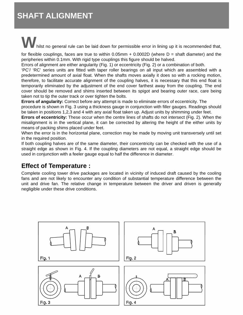
Whilst no general rule can be laid down for permissible error in lining up it is recommended that,
for flexible couplings, faces are true to within 0.05mm + 0.0002D (where D = shaft diameter) and theperipheries within 0.1mm. With rigid type couplings this figure should be halved.Errors of alignment are either angularity (Fig. 1) or eccentricity (Fig. 2) or a combination of both.‘PC’/ ‘RC’ series units are fitted with taper roller bearings on all input which are assembled with apredetermined amount of axial float. When the shafts moves axially it does so with a rocking motion,therefore to facilitate accurate alignment of the coupling halves it is necessary that this end float istherefore, to facilitate accurate alignment of the coupling halves, it is necessary that this end float istemporarily eliminated by the adjustment of the end cover farthest away from the coupling. The endcover should be removed and shims inserted between its spigot and bearing outer race, care beingtaken not to tip the outer track or over tighten the bolts.Errors of angularity: Correct before any attempt is made to eliminate errors of eccentricity. Theprocedure is shown in Fig. 3 using a thickness gauge in conjunction with filler gauges. Readings shouldbe taken in positions 1,2,3 and 4 with any axial float taken up. Adjust units by shimming under feet.Errors of eccentricity: These occur when the centre lines of shafts do not intersect (Fig. 2). When theErrors of eccentricity: These occur when the centre lines of shafts do not intersect (Fig. 2). When themisalignment is in the vertical plane, it can be corrected by altering the height of the either units bymeans of packing shims placed under feet.When the error is in the horizontal plane, correction may be made by moving unit transversely until setin the required position.If both coupling halves are of the same diameter, their concentricity can be checked with the use of astraight edge as shown in Fig. 4. If the coupling diameters are not equal, a straight edge should beused in conjunction with a feeler gauge equal to half the difference in diameter.
Effect of Temperature :Complete cooling tower drive packages are located in vicinity of induced draft caused by the coolingfans and are not likely to encounter any condition of substantial temperature difference between theunit and drive fan. The relative change in temperature between the driver and driven is generallynegligible under these drive conditions.
GEARS
GGears :Premium Cooling tower units are fitted with either spiral bevel gear throughout or a combination of spiralbevel gears and single helical. The spiral bevel gears are lap-finished in pairs and helical gears are casehardened and profile ground; all to give the highest standard of accuracy and finish while giving it itsquiet running characteristics.
T th t t (S i l b l )Tooth contact (Spiral bevels) :In the event of the gears being disturbed, it will be necessary to check tooth contact of the bevel gears iffitted, as per recommended procedure laid out below:
1. Assemble unit including the top bearing housing cover but without input shaft.
2. Assemble input bearing housing assembly nipping lock-nut up against bearing.
3. Fit bearing housing assembly to case without shims, ensuring that the back faces of the mating gearsare flush with each other.
4. There should at this point, be a gap between bearing housing and case. This gap should bemeasured and shims added equal to it.Note: Operations 3 and 4 may be ignored if same gears are being refitted, In this case the old shimsor new one equivalent to them may be fitted.or new one equivalent to them may be fitted.
5. Bolt bearing hosing to case, tightening bolts.
6. Using side inspection cover, apply engineers blue to both flanks of pinion teeth.
7. Rotate gears slowly until a well defined contact marking has been produced on the wheel.
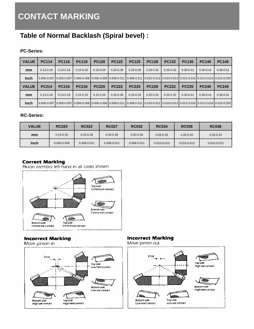
8. Compare tooth markings with the diagrams shown on adjacent page.
9. If tooth marking are not in the first diagram, remove bearing housing anda) Add more shims if marking are as in second diagramb) Reduce shimming if marking are as in third diagram
10.Repeat operations as from 5.
Note: After attaining the correct tooth marking, the backlash should be checked (see table on theadjacent page).
If backlash is excessive, both bevel gears should be adjusted towards their apexes by adjusting theshims accordingly. Adjustment in the opposite direction will increase backlash in the bevel gears.
Note: Gears may be observed through side inspection cover.y g p
CONTACT MARKING
Table of Normal Backlash (Spiral bevel) :
PC-Series:
VALUE PC114 PC116 PC118 PC120 PC122 PC125 PC128 PC132 PC135 PC140 PC145
mm 0.13-0.18 0.13-0.18 0.15-0.20 0.15-0.20 0.20-0.28 0.20-0.28 0.25-0.33 0.25-0.33 0.30-0.41 0.30-0.41 0.38-0.51
Inch 0.005-0.007 0.005-0.007 0.006-0.008 0.006-0.008 0.008-0.011 0.008-0.011 0.010-0.013 0.010-0.013 0.012-0.016 0.012-0.016 0.015-0.020
RC-Series:
VALUE PC214 PC216 PC218 PC220 PC222 PC225 PC228 PC232 PC235 PC240 PC245
mm 0.13-0.18 0.13-0.18 0.15-0.20 0.15-0.20 0.20-0.28 0.20-0.28 0.25-0.33 0.25-0.33 0.30-0.41 0.30-0.41 0.38-0.51
Inch 0.005-0.007 0.005-0.007 0.006-0.008 0.006-0.008 0.008-0.011 0.008-0.011 0.010-0.013 0.010-0.013 0.012-0.016 0.012-0.016 0.015-0.020
VALUE RC020 RC022 RC027 RC032 RC034 RC036 RC038
mm 0.15-0.20 0.20-0.28 0.20-0.28 0.20-0.28 0.25-0.33 0.25-0.33 0.25-0.33
Inch 0.006-0.008 0.008-0.011 0.008-0.011 0.008-0.011 0.010-0.013 0.010-0.013 0.010-0.013
BEARINGS
BBearings :The bearings for ‘PC’/’RC’-Series are selected very carefully to best suit the requirements ofeach unit and to more than adequately deal with the designed maximum loads acting on them.Because of the load carrying capacity at higher speeds, taper roller bearings / spherical rollerbearings are used throughout.
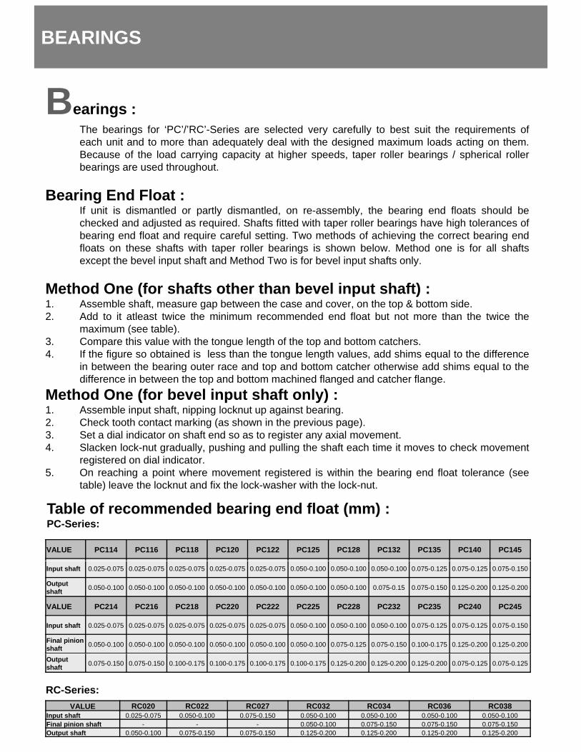
B i E d Fl tBearing End Float :If unit is dismantled or partly dismantled, on re-assembly, the bearing end floats should bechecked and adjusted as required. Shafts fitted with taper roller bearings have high tolerances ofbearing end float and require careful setting. Two methods of achieving the correct bearing endfloats on these shafts with taper roller bearings is shown below. Method one is for all shaftsexcept the bevel input shaft and Method Two is for bevel input shafts only.
M th d O (f h ft th th b l i t h ft)Method One (for shafts other than bevel input shaft) :1. Assemble shaft, measure gap between the case and cover, on the top & bottom side.2. Add to it atleast twice the minimum recommended end float but not more than the twice the
maximum (see table).3. Compare this value with the tongue length of the top and bottom catchers.4. If the figure so obtained is less than the tongue length values, add shims equal to the difference
in between the bearing outer race and top and bottom catcher otherwise add shims equal to thediff i b t th t d b tt hi d fl d d t h fldifference in between the top and bottom machined flanged and catcher flange.
Method One (for bevel input shaft only) :1. Assemble input shaft, nipping locknut up against bearing.2. Check tooth contact marking (as shown in the previous page).3. Set a dial indicator on shaft end so as to register any axial movement.4. Slacken lock-nut gradually, pushing and pulling the shaft each time it moves to check movement
registered on dial indicator.O f (5. On reaching a point where movement registered is within the bearing end float tolerance (seetable) leave the locknut and fix the lock-washer with the lock-nut.
Table of recommended bearing end float (mm) :PC-Series:
VALUE PC114 PC116 PC118 PC120 PC122 PC125 PC128 PC132 PC135 PC140 PC145
Input shaft 0.025-0.075 0.025-0.075 0.025-0.075 0.025-0.075 0.025-0.075 0.050-0.100 0.050-0.100 0.050-0.100 0.075-0.125 0.075-0.125 0.075-0.150
Output shaft 0.050-0.100 0.050-0.100 0.050-0.100 0.050-0.100 0.050-0.100 0.050-0.100 0.050-0.100 0.075-0.15 0.075-0.150 0.125-0.200 0.125-0.200
VALUE PC214 PC216 PC218 PC220 PC222 PC225 PC228 PC232 PC235 PC240 PC245
Input shaft 0.025-0.075 0.025-0.075 0.025-0.075 0.025-0.075 0.025-0.075 0.050-0.100 0.050-0.100 0.050-0.100 0.075-0.125 0.075-0.125 0.075-0.150
Final pinion shaft 0.050-0.100 0.050-0.100 0.050-0.100 0.050-0.100 0.050-0.100 0.050-0.100 0.075-0.125 0.075-0.150 0.100-0.175 0.125-0.200 0.125-0.200
RC-Series:
Outputshaft 0.075-0.150 0.075-0.150 0.100-0.175 0.100-0.175 0.100-0.175 0.100-0.175 0.125-0.200 0.125-0.200 0.125-0.200 0.075-0.125 0.075-0.125
VALUE RC020 RC022 RC027 RC032 RC034 RC036 RC038Input shaft 0.025-0.075 0.050-0.100 0.075-0.150 0.050-0.100 0.050-0.100 0.050-0.100 0.050-0.100Final pinion shaft - - - 0.050-0.100 0.075-0.150 0.075-0.150 0.075-0.150Output shaft 0.050-0.100 0.075-0.150 0.075-0.150 0.125-0.200 0.125-0.200 0.125-0.200 0.125-0.200
OIL SEALS
R l t f il lReplacement of oilseals :Oil seals should be replaced whenever unit is dismantled or if in service it shows sign of leakageor damage.
Recommended procedure for replacing oilseal :1. Clean and drain unit.2 Remove any part that may obstruct access to the oil seal (e g Coupling / Guards etc )2. Remove any part that may obstruct access to the oil seal (e.g. Coupling / Guards etc.)3. Remove bolts and withdraw oil catcher. Take care not to damage the shims and do not alter the
shaft position. Check for burrs and scratches on the seals as these could damage the new seal.4. Tap the old seals out of the housing.5. Clean joint faces and shims.6. Position shims on oil catcher.7. Coat joint faces of oil catcher and gearcase with a good joining compound.8. Replace oil catcher and tighten bolts.8. Replace oil catcher and tighten bolts.9. For new oilseals, protect seal lips by wrapping shaft with thin strong paper coated with oil or
grease. Coat seal lips with grease, then using appropriate sized adaptor, drift press into flangeadaptor plate. For proper functioning always ensure that seal is seated square with the coupler.
10. Fill unit with a recommended lubricant to correct levels as indicated on the dipstick.
OPERATION
Operation :No special break-in procedures are necessary except as noted under lubrication.
Each unit is subjected to a running test at the works to assure smooth and quiet operation Excessive noiseEach unit is subjected to a running test at the works to assure smooth and quiet operation. Excessive noiseor vibration at initial operation is an indication of one or a combination of the following :
(1) Misalignment,
(2) Imbalance of fan or other rotating parts,
(3) Improperly adjusted fan blades,
(4) Torsional vibrations,
(5) Unstable mounting
If noise or vibration persists, shut the unit down and correct the fault before further operation.
OPTIONAL FEATURES
UUnits with roller holdback / backstop device:
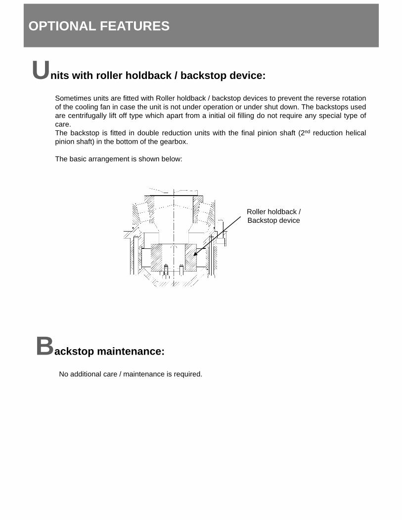
Sometimes units are fitted with Roller holdback / backstop devices to prevent the reverse rotationof the cooling fan in case the unit is not under operation or under shut down. The backstops usedare centrifugally lift off type which apart from a initial oil filling do not require any special type ofcare.The backstop is fitted in double reduction units with the final pinion shaft (2nd reduction helicalThe backstop is fitted in double reduction units with the final pinion shaft (2nd reduction helicalpinion shaft) in the bottom of the gearbox.
The basic arrangement is shown below:
Roller holdback /Backstop device
Backstop maintenance:
No additional care / maintenance is required.
LUBRICATION AND LUBRICANTS
Lubrication :
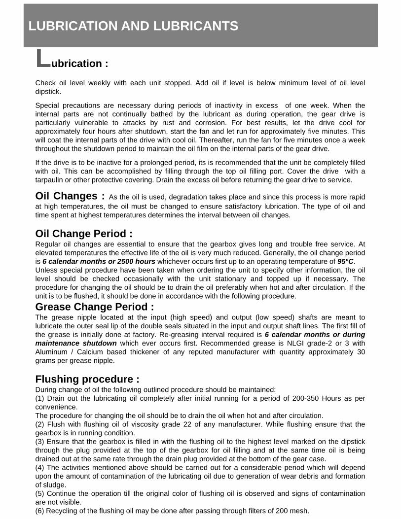
Check oil level weekly with each unit stopped. Add oil if level is below minimum level of oil leveldipstick.
Special precautions are necessary during periods of inactivity in excess of one week. When theinternal parts are not continually bathed by the lubricant as during operation, the gear drive isparticularly vulnerable to attacks by rust and corrosion. For best results, let the drive cool forapproximately four hours after shutdown start the fan and let run for approximately five minutes Thisapproximately four hours after shutdown, start the fan and let run for approximately five minutes. Thiswill coat the internal parts of the drive with cool oil. Thereafter, run the fan for five minutes once a weekthroughout the shutdown period to maintain the oil film on the internal parts of the gear drive.
If the drive is to be inactive for a prolonged period, its is recommended that the unit be completely filledwith oil. This can be accomplished by filling through the top oil filling port. Cover the drive with atarpaulin or other protective covering. Drain the excess oil before returning the gear drive to service.
Oil Changes : A th il i d d d ti t k l d i thi i idOil Changes : As the oil is used, degradation takes place and since this process is more rapidat high temperatures, the oil must be changed to ensure satisfactory lubrication. The type of oil andtime spent at highest temperatures determines the interval between oil changes.
Oil Change Period :Regular oil changes are essential to ensure that the gearbox gives long and trouble free service. Atelevated temperatures the effective life of the oil is very much reduced. Generally, the oil change periodi 6 l d th 2500 h hi h fi t t ti t t f 95°Cis 6 calendar months or 2500 hours whichever occurs first up to an operating temperature of 95°C.Unless special procedure have been taken when ordering the unit to specify other information, the oillevel should be checked occasionally with the unit stationary and topped up if necessary. Theprocedure for changing the oil should be to drain the oil preferably when hot and after circulation. If theunit is to be flushed, it should be done in accordance with the following procedure.Grease Change Period :The grease nipple located at the input (high speed) and output (low speed) shafts are meant tol b i t th t l li f th d bl l it t d i th i t d t t h ft li Th fi t fill flubricate the outer seal lip of the double seals situated in the input and output shaft lines. The first fill ofthe grease is initially done at factory. Re-greasing interval required is 6 calendar months or duringmaintenance shutdown which ever occurs first. Recommended grease is NLGI grade-2 or 3 withAluminum / Calcium based thickener of any reputed manufacturer with quantity approximately 30grams per grease nipple.
Flushing procedure :D i h f il th f ll i tli d d h ld b i t i dDuring change of oil the following outlined procedure should be maintained:(1) Drain out the lubricating oil completely after initial running for a period of 200-350 Hours as perconvenience.The procedure for changing the oil should be to drain the oil when hot and after circulation.(2) Flush with flushing oil of viscosity grade 22 of any manufacturer. While flushing ensure that thegearbox is in running condition.(3) Ensure that the gearbox is filled in with the flushing oil to the highest level marked on the dipstickthrough the plug provided at the top of the gearbox for oil filling and at the same time oil is beingthrough the plug provided at the top of the gearbox for oil filling and at the same time oil is beingdrained out at the same rate through the drain plug provided at the bottom of the gear case.(4) The activities mentioned above should be carried out for a considerable period which will dependupon the amount of contamination of the lubricating oil due to generation of wear debris and formationof sludge.(5) Continue the operation till the original color of flushing oil is observed and signs of contaminationare not visible.(6) Recycling of the flushing oil may be done after passing through filters of 200 mesh.
LUBRICATANTS & SHIPPING SPEC.:
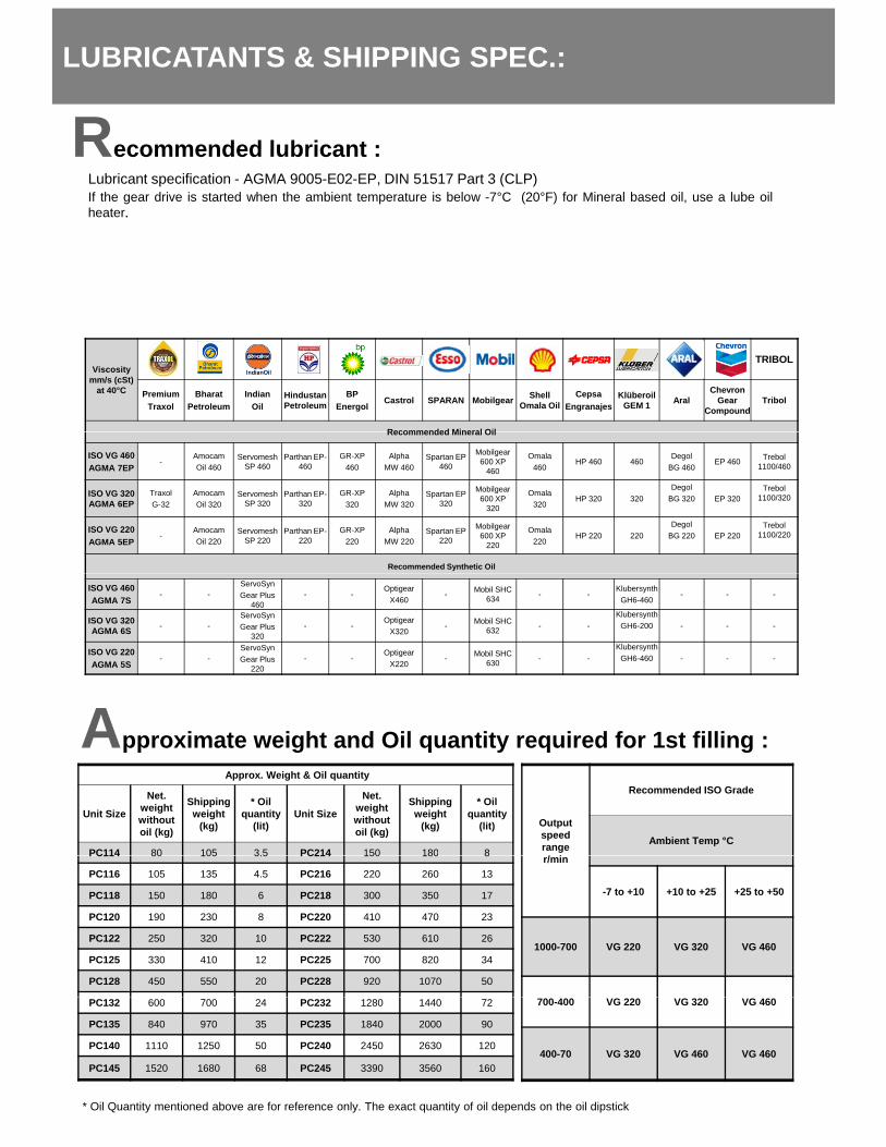
Recommended lubricant :Recommended lubricant :Lubricant specification - AGMA 9005-E02-EP, DIN 51517 Part 3 (CLP)If the gear drive is started when the ambient temperature is below -7°C (20°F) for Mineral based oil, use a lube oilheater..
Viscosity mm/s (cSt)
at 40°C
TRIBOL
PremiumTraxol
BharatPetroleum
IndianOil
Hindustan Petroleum
BPEnergol
Castrol SPARAN Mobilgear Shell Omala Oil
CepsaEngranajes
Klüberoil GEM 1 Aral
Chevron Gear
CompoundTribol
Recommended Mineral OilRecommended Mineral Oil
ISO VG 460AGMA 7EP
-AmocamOil 460
ServomeshSP 460
Parthan EP-460
GR-XP460
AlphaMW 460
Spartan EP 460
Mobilgear600 XP
460
Omala460
HP 460 460Degol
BG 460EP 460 Trebol
1100/460
ISO VG 320AGMA 6EP
TraxolG-32
AmocamOil 320
ServomeshSP 320
Parthan EP-320
GR-XP320
AlphaMW 320
Spartan EP 320
Mobilgear600 XP
320
Omala320
HP 320 320Degol
BG 320 EP 320Trebol
1100/320
ISO VG 220AGMA 5EP
-AmocamOil 220
Servomesh SP 220
Parthan EP-220
GR-XP220
AlphaMW 220
Spartan EP 220
Mobilgear600 XP
220
Omala220
HP 220 220Degol
BG 220 EP 220Trebol
1100/220
Recommended Synthetic Oil
A
ISO VG 460AGMA 7S
- -ServoSynGear Plus
460- -
OptigearX460
- Mobil SHC 634 - -
KlubersynthGH6-460
- - -
ISO VG 320AGMA 6S - -
ServoSynGear Plus
320- -
OptigearX320
- Mobil SHC 632 - -
KlubersynthGH6-200 - - -
ISO VG 220AGMA 5S
- -ServoSynGear Plus
220- -
OptigearX220
- Mobil SHC 630 - -
KlubersynthGH6-460 - - -
Approximate weight and Oil quantity required for 1st filling :Approx. Weight & Oil quantity
Unit Size
Net. weight without oil (kg)
Shipping weight
(kg)
* Oil quantity
(lit)Unit Size
Net. weight without oil (kg)
Shipping weight
(kg)
* Oil quantity
(lit)
PC114 80 105 3.5 PC214 150 180 8
Output speed range / i
Recommended ISO Grade
Ambient Temp °CPC114 80 105 3.5 PC214 150 180 8
PC116 105 135 4.5 PC216 220 260 13
PC118 150 180 6 PC218 300 350 17
PC120 190 230 8 PC220 410 470 23
PC122 250 320 10 PC222 530 610 26
PC125 330 410 12 PC225 700 820 34
PC128 450 550 20 PC228 920 1070 50
r/min
-7 to +10 +10 to +25 +25 to +50
1000-700 VG 220 VG 320 VG 460
PC132 600 700 24 PC232 1280 1440 72
PC135 840 970 35 PC235 1840 2000 90
PC140 1110 1250 50 PC240 2450 2630 120
PC145 1520 1680 68 PC245 3390 3560 160
700-400 VG 220 VG 320 VG 460
400-70 VG 320 VG 460 VG 460
* Oil Quantity mentioned above are for reference only. The exact quantity of oil depends on the oil dipstick
MAINTENANCE
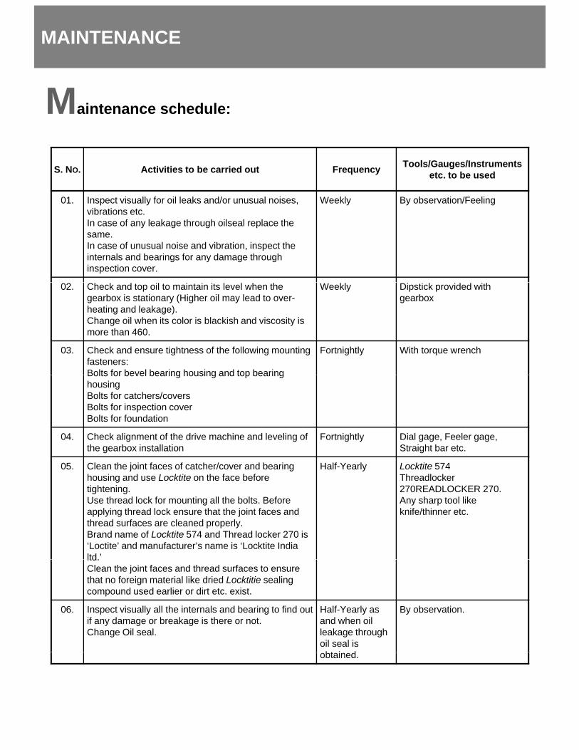
MMaintenance schedule:
S. NO. Activities to be carried out Frequency Tools/Gauges/Instrumentsetc. to be used
01. Inspect visually for oil leaks and/or unusual noises, vibrations etc.In case of any leakage through oilseal replace the same.In case of unusual noise and vibration, inspect the internals and bearings for any damage through inspection cover.
Weekly By observation/Feeling
02. Check and top oil to maintain its level when the gearbox is stationary (Higher oil may lead to over-heating and leakage).Change oil when its color is blackish and viscosity is more than 460.
Weekly Dipstick provided with gearbox
03. Check and ensure tightness of the following mounting fasteners:Bolts for bevel bearing housing and top bearing
Fortnightly With torque wrench
Bolts for bevel bearing housing and top bearing housingBolts for catchers/coversBolts for inspection coverBolts for foundation
04. Check alignment of the drive machine and leveling of the gearbox installation
Fortnightly Dial gage, Feeler gage, Straight bar etc.
05 Clean the joint faces of catcher/cover and bearing Half-Yearly Locktite 57405. Clean the joint faces of catcher/cover and bearing housing and use Locktite on the face before tightening.Use thread lock for mounting all the bolts. Before applying thread lock ensure that the joint faces and thread surfaces are cleaned properly.Brand name of Locktite 574 and Thread locker 270 is ‘Loctite’ and manufacturer’s name is ‘Locktite India ltd.’
Half-Yearly Locktite 574Threadlocker270READLOCKER 270.Any sharp tool like knife/thinner etc.
ltd.Clean the joint faces and thread surfaces to ensure that no foreign material like dried Locktitie sealing compound used earlier or dirt etc. exist.
06. Inspect visually all the internals and bearing to find out if any damage or breakage is there or not.Change Oil seal.
Half-Yearly as and when oil leakage through oil seal is
bt i d
By observation.
obtained.
T
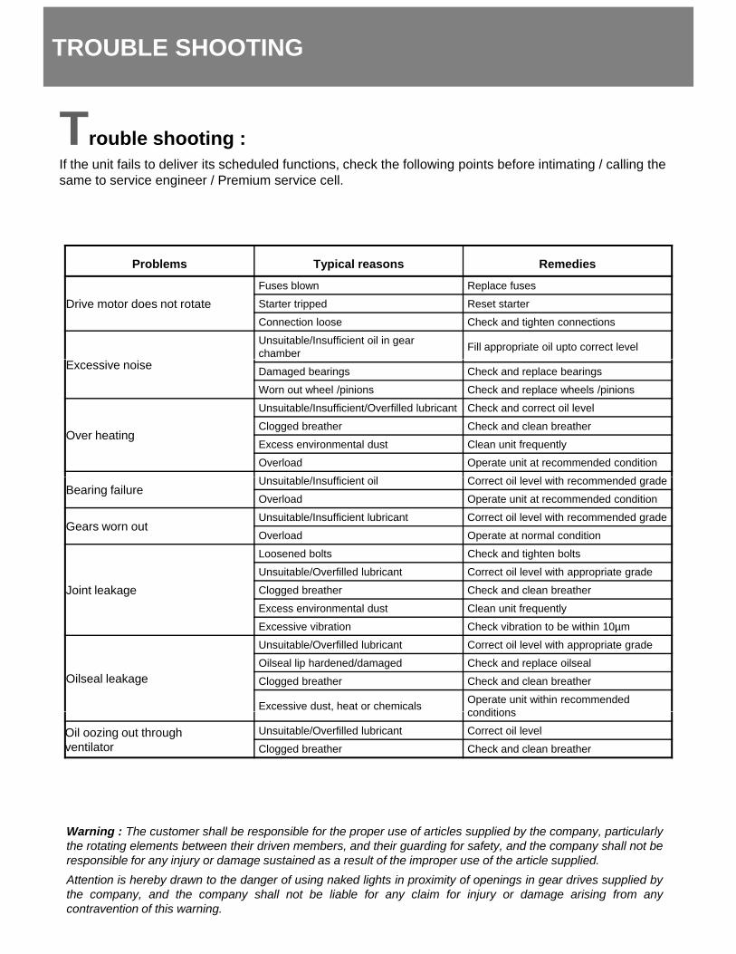
TROUBLE SHOOTING
Trouble shooting :If the unit fails to deliver its scheduled functions, check the following points before intimating / calling the same to service engineer / Premium service cell.
Problems Typical reasons Remedies
Drive motor does not rotateFuses blown Replace fuses
Starter tripped Reset starter
Connection loose Check and tighten connections
Unsuitable/Insufficient oil in gear chamber Fill appropriate oil upto correct level
Excessive noise Damaged bearings Check and replace bearings
Worn out wheel /pinions Check and replace wheels /pinions
Over heating
Unsuitable/Insufficient/Overfilled lubricant Check and correct oil level
Clogged breather Check and clean breather
Excess environmental dust Clean unit frequently
Overload Operate unit at recommended condition
U i bl /I ffi i il C il l l i h d d dBearing failure
Unsuitable/Insufficient oil Correct oil level with recommended grade
Overload Operate unit at recommended condition
Gears worn outUnsuitable/Insufficient lubricant Correct oil level with recommended grade
Overload Operate at normal condition
Joint leakage
Loosened bolts Check and tighten bolts
Unsuitable/Overfilled lubricant Correct oil level with appropriate grade
Clogged breather Check and clean breatherJo t ea age gg
Excess environmental dust Clean unit frequently
Excessive vibration Check vibration to be within 10µm
Oilseal leakage
Unsuitable/Overfilled lubricant Correct oil level with appropriate grade
Oilseal lip hardened/damaged Check and replace oilseal
Clogged breather Check and clean breather
Excessive dust, heat or chemicals Operate unit within recommended conditions
Warning : The customer shall be responsible for the proper use of articles supplied by the company particularly
conditions
Oil oozing out through ventilator
Unsuitable/Overfilled lubricant Correct oil level
Clogged breather Check and clean breather
Warning : The customer shall be responsible for the proper use of articles supplied by the company, particularlythe rotating elements between their driven members, and their guarding for safety, and the company shall not beresponsible for any injury or damage sustained as a result of the improper use of the article supplied.Attention is hereby drawn to the danger of using naked lights in proximity of openings in gear drives supplied bythe company, and the company shall not be liable for any claim for injury or damage arising from anycontravention of this warning.
Single reduction units :
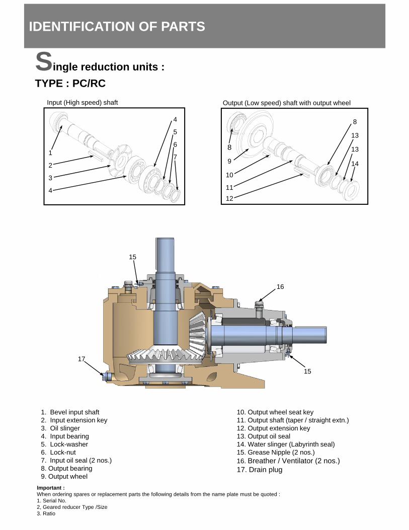
IDENTIFICATION OF PARTS
Single reduction units :TYPE : PC/RC
Output (Low speed) shaft with output wheel
8
13
Input (High speed) shaft
4
5
8
9
10
1112
13
13
141
2
3
4
6
7
12
15
16
15
17
1. Bevel input shaft2. Input extension key3. Oil slinger4. Input bearing5. Lock-washer6. Lock-nut7 Input oil seal (2 nos )
10. Output wheel seat key11. Output shaft (taper / straight extn.)12. Output extension key13. Output oil seal14. Water slinger (Labyrinth seal)15. Grease Nipple (2 nos.)16 Breather / Ventilator (2 nos )7. Input oil seal (2 nos.)
8. Output bearing9. Output wheel
16. Breather / Ventilator (2 nos.)17. Drain plug
Important : When ordering spares or replacement parts the following details from the name plate must be quoted :1. Serial No.2, Geared reducer Type /Size3. Ratio

Double reduction units :
IDENTIFICATION OF PARTS
Double reduction units :TYPE : PC/RC
Input (High speed) shaft
4
5
6
Final pinion shaft with bevel wheel
5
128
1
2
3
4
6
75
8910
11
Output (Low speed) shaft with output wheel
13
14
15
13
18
18
19
1
1617
Roller Holdback with final pinion shaft
20
2122
22
21
1. Bevel input shaft2. Input extension key3. Oil slinger4. Input bearing5. Lock-washer6 Lock nut
8. Final pinion shaft bearing9. Final pinion shaft10. Bevel wheel11. Final reduction distance piece12. Final reduction wheel seat key13 Output bearing
15. Output wheel seat key16. Output shaft (taper / straight extn.)17. Output extension key18. Output oil seal19. Water slinger (Labyrinth seal)20 Roller holdback / backstop (optional)
2123
6. Lock-nut7. Input oil seal (2 nos.)
13. Output bearing14. Output wheel
20. Roller holdback / backstop (optional)21. Grease Nipple (2 nos.)22. Breather / Ventilator (2 nos.)23. Drain plug (hidden)Important :
When ordering spares or replacement parts the following details from the name plate must be quoted :1. Serial No.2, Geared reducer Type /Size3. Ratio


![Bevel and hypoid gearing - geometry [ISO 23509] i Pinion ... · 3.0 3.1 Nominal design pressure angle drive side / coast side alfadD, alfadC 20.0000 20.0000 [°] 3.2 Influence factor](https://img.pdfslide.us/doc/110x75/5e0bf82619b0043db24e5b88/bevel-and-hypoid-gearing-geometry-iso-23509-i-pinion-30-31-nominal-design.jpg)