Embed Size (px)
Citation preview
S2 S1 NSB SL L N S2 S1 NSB SL L N S2 S1 NSB SL L N S2 S1 NSB SL L N S2 S1 NSB SL L N S2 S1 NSB SL L N S2 S1 NSB SL L N S2 S1 NSB SL L N
Group ControlPROGRAMMABLE
THERMOSTAT 22-23003
Group Control PROGRAMMABLE
THERMOSTAT 22-23003
N L
NL
NL
L
L N
P1 UT P2 UT
PÅ AV
1 2 3 4 5
GROUP2
DIGITAL THERMOSTAT
22-23002
DIGITALTHERMOSTAT
22-23002
DIGITALTHERMOSTAT
22-23002
GROUP1
DIAL THERMOSTAT 22-23001
DIAL THERMOSTAT 22-23001
SUPPLIED CABLES
UNDERFLOOR HEATING MANIFOLD
EXTERNAL CLOCK SUPPLY
External power supply
Optional boiler connection
0 Volt connection
1.5MM2 CABLE (INSTALLER SUPPLIED)
OPTIONAL EXTERNAL
CLOCK
N S2 S1 NSB SL L
22-23002
S1 NSB SL L
22-23002
N S2 2 S1 NSB SL L N
22-23002
N S2
2
N S2 S1 NSB SL L N
PROGRAMMABLE
THERMOSTAT 22-23002
These instructions apply to the model stated above.
Warning This product must be fitted by a competent person, and installation must comply with the guidance, standards and regulations applicable to the country or state where the product is installed. Failure to comply with the requirements of the relevant guidance, standards and regulations could lead to injury, death or prosecution.
Warning Always isolate the AC mains supply before installing or working on any components that require 230 V AC 50Hz supply.
Warning The earth terminals on the Wiring Centre for 230V are for earth parking only. These terminals provide no earth protection.
Meets the following EC Directives• Electro-Magntic Compatibility directive 2014/30/EU• Low-voltage Directive 2014/35/EU• Restriction of Hazardous Substances Directive 2011/65/EU
www.multipipe.co.uk Technical Helpline: 01245 850799
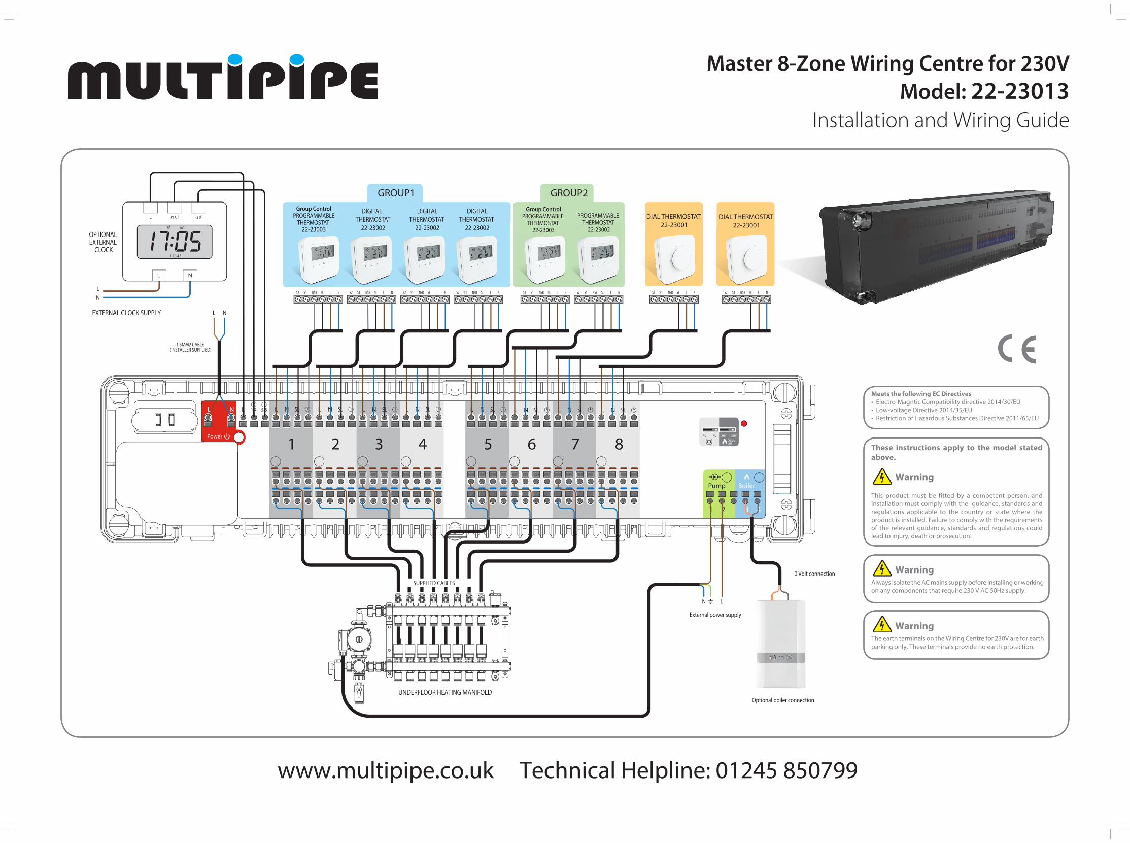
Master 8-Zone Wiring Centre for 230V Model: 22-23013
Installation and Wiring Guide

1 Remove the plastic cover. Open (and close) the four white screws with a quarter turn only. Note that screws on opposite sides turn in the opposite direction.
2 Remove the white terminal connection board.
3 Attach the back of the Wiring Centre for 230V to the DIN rail or wall.
5 Clip all power and thermostat cables into their correct positions. The following shows the power, zone 1, and 2 thermostat cables in position:
6 Replace the white terminal connection board.
7 Bend over and push the power wires into the round power holes.
8 Bend over and push all thermostat wires into the round holes at the top of the Wiring Centre for 230V.
9 Push the actuator wires into the round holes at the bottom of the Wiring Centre for 230V. You can connect up to four actuators in each zone.
10 Make sure there is a fuse in thefuse holder.
11 Set the actuator and boiler delay jumpers at the top right of the Wiring Centre for 230V.
12 Push in the wires for a pump and boiler (if applicable) at the bottom right of the Wiring Centre for 230V.Pump and boiler switching is volt free.
13 Attach the red strain-relieving strip using the three screws to secure the pump and boiler wires to the bottom side of the Wiring Centre for 230V.
14 Replace the plastic cover.
15 Switch on mains power supply to the unit. The red LED comes on.
LED indicationsName Colour Meaning
Power • Wiring Centre for 230V is supplied with 230V powerZone 1 actuators • Demand from zone 1 thermostat: actuator openZone 2 actuators • Demand from zone 2 thermostat: actuator openZone 3 actuators • Demand from zone 3 thermostat: actuator openZone 4 actuators • Demand from zone 4 thermostat: actuator openZone 5 actuators • Demand from zone 5 thermostat: actuator openZone 6 actuators • Demand from zone 6 thermostat: actuator openZone 7 actuators • Demand from zone 7 thermostat: actuator openZone 8 actuators • Demand from zone 8 thermostat: actuator openPump • Pump onBoiler • Boiler on
Installing and Connectingthe Wiring Centre for 230VUse the Wiring Centre for 230V wiring centre to simply and safely connect thermostats and corresponding thermal actuators. It can have three different physical configurations:
• Two groups of thermostats, each group having up to four thermostats.
• Three groups of thermostats with a wiring centre extension attached, each group having up to four thermostats.
• A master thermostat controlling up to seven slave thermostats. For this configuration, you must make a bridge between grey positions 1-4 and 5-8. If an extension is attached to the Wiring Centre for 230V, this is not included in this configuration and another master thermostat will control the slaves connected to the extention on zones 9 to 12.
Install the Wiring Centre for 230V only in dry and closed interior rooms. Relative air humidity in the room may not exceed 95%. Clean the Wiring Centre for 230V only with a dry and soft cloth. Do not use solvents or aggressive cleaning agents.
4 Cut the power, thermostat anddevice cables to length.
Device
Power/Thermostat
50mm
110mm
10mm
10mm
Type of ActuatorThe default setting for the type of actuatoris normally closed (NC). To change this settingto normally open (NO), carefully remove the jumper and re-insert it in the other positionas shown below. Note that the actuator setting and thermostat setting must be the same.
Jumper Settings/Positions for Pump/Boiler On/Off DelayThe pump/boiler on delay and the pump off delay are fixed at three minutes. The default setting for the boiler off delay is also three minutes, but can be changed to 15 minutes. To do this, carefully remove the jumper and re-insert it in the other position as shown below:
Note: the red reset button to the right of the boiler delay jumpers. Using a suitable tool, press this button at any time to reset the Wiring Centre for 230V back to factory default settings.
Master 8-Zone Wiring Centre for 230V Model: 22-23013
Installation and Wiring Guide