Embed Size (px)
Citation preview

DORMA
WN
05
80
29
4
55
32
11
/11
ES 400 DIN 18650
Anschlussplatine Umtausch
Replacement of the connection board
DORMA
WN
05
80
29
4
55
32
11
/11
02
Inhaltsverzeichnis 11.2011 Contents 11/2011
Seite page
Inhaltsverzeichnis 2 Contents 2Anschlußplatine Umtausch 3 - 4 Replacement of the connection board 3 - 4
Klemmendefinition 5 Terminal definition 5
Anschlusspläne Wiring diagramSchleusenaufbau und Anschlussplan 6 Airlock system and its wiring diagram 6Anschlussplan Melder Allgemein 7 Wiring diagram for radar motion detector 7Anschlussplan Melder Jupiter 8 Wiring diagram for radar motion Jupiter 8Anschlussplan Melder Activ8 One On 9 Wiring diagram for radar motion Activ8 One On 9Anschlussplan Melder IRIS ON 10-11 Wiring diagram for radar motion IRIS ON 10-11Anschlussplan Treibriegelschaltkontakt 12 Wiring diagram for latch bolt limit switch 12
Originalbetriebsanleitung Translation of the original documentation
Dargestellt ist die Montage einer rechtsöffnenden Tür. The mounting instruction is shown a left hand door.Für eine linksöffnende Tür bitte spiegelbildlich arbeiten. Mirrored arragements apply for a right hand door.
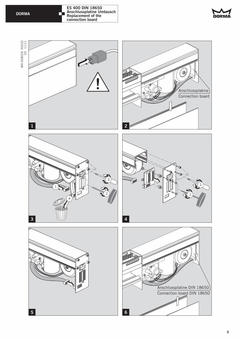
ES 400 DIN 18650Anschlussplatine UmtauschReplacement of the connection board
1
Anschlussplatine DIN 18650
Connection board DIN 18650
DORMA
WN
05
80
29
4
55
32
11
/11
3
Anschlussplatine
Connection board
5
3.
1.
2. 1.
2.
2
4
6
4.
ES 400 DIN 18650Anschlussplatine UmtauschReplacement of the connection board
03
3

DORMA
WN
05
80
29
4
55
32
11
/11
RESET
1.3.
2.
DIN 18650
DIN 18650
8
9
DIN 18650
2.
1.
7
04
ES 400 DIN 18650Anschlussplatine UmtauschReplacement of the connection board
DORMA
WN
05
80
29
4
55
32
11
/11
28 VAC
230 VAC
X2X1
4
3
1
2
5
76 1
12
13
24
05
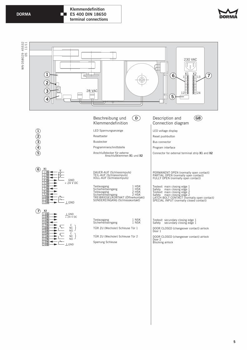
ES 400 DIN 18650Klemmendefinition
terminal connections
X1
LED Spannungsanzeige
Resettaster
Busstecker
Programmierschnittstelle
Anschlußstecker für externeAnschlußklemmen X1 und X2
DAUER-AUF (Schliessimpuls)TEIL-AUF (Schliessimpuls)VOLL-AUF (Schliessimpuls)
Testausgang 1 HSKSicherheitseingang 1 HSKTestausgang 2 HSKSicherheitseingang 2 HSKTREIBRIEGELKONTAKT (Öffnerkontakt)SONDEREINGANG (Schliesskontakt)
Testausgang 1 NSKSicherheitseingang 1 NSK
TÜR ZU (Wechsler) Schleuse Tür 1
TÜR ZU (Wechsler) Schleuse Tür 2
Sperrung Schleuse
123456789
101112
131415161718192021222324
DBeschreibung und Klemmendefinition
GBDescription and Connection diagram
GND+ 24 V DC
CNCNOC
NCNO
GND
GND+ 24 V DC
GND
X2
1
2
3
4
5
6
7
LED voltage display
Reset pushbutton
Bus connector
Program interface
Connector for external terminal strip X1 and X2
PERMANENT OPEN (normally open contact)PARTIAL OPEN (normally open contact)FULLY OPEN (normally open contact)
Testexit main closing edge 1Safety main closing edge 1Testexit main closing edge 2Safety main closing edge 2LATCH BOLT CONTACT (normally open contact)SPECIAL INPUT (normally closed contact)
Testexit secundary closing edge 1Safety secundary closing edge 1
DOOR CLOSED (changeover contact) airlockDoor 1
DOOR CLOSED (changeover contact) airlockDoor 2Blocking airlock
5
DORMA
WN
05
80
29
4
55
32
11
/11
1.
2.
3.
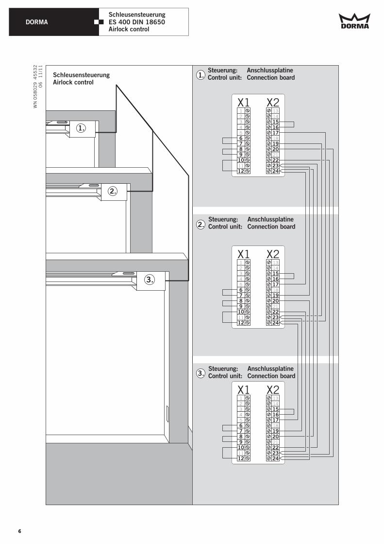
SchleusensteuerungAirlock control
X2X112345
11
6789
10
12
1314
18
21
151617
1920
222324
X2X112345
11
6789
10
12
1314
18
21
151617
1920
222324
X2X112345
11
6789
10
12
1314
18
21
151617
1920
222324
1.
2.
3.
Steuerung:Control unit: Connection board
Anschlussplatine
Steuerung:Control unit: Connection board
Anschlussplatine
Steuerung:Control unit: Connection board
Anschlussplatine
06
ES 400 DIN 18650Schleusensteuerung
Airlock control
DORMA
WN
05
80
29
4
55
32
11
/11
07
X2X112
5
11
34
6789
10
12
1314
18
21
151617
1920
222324
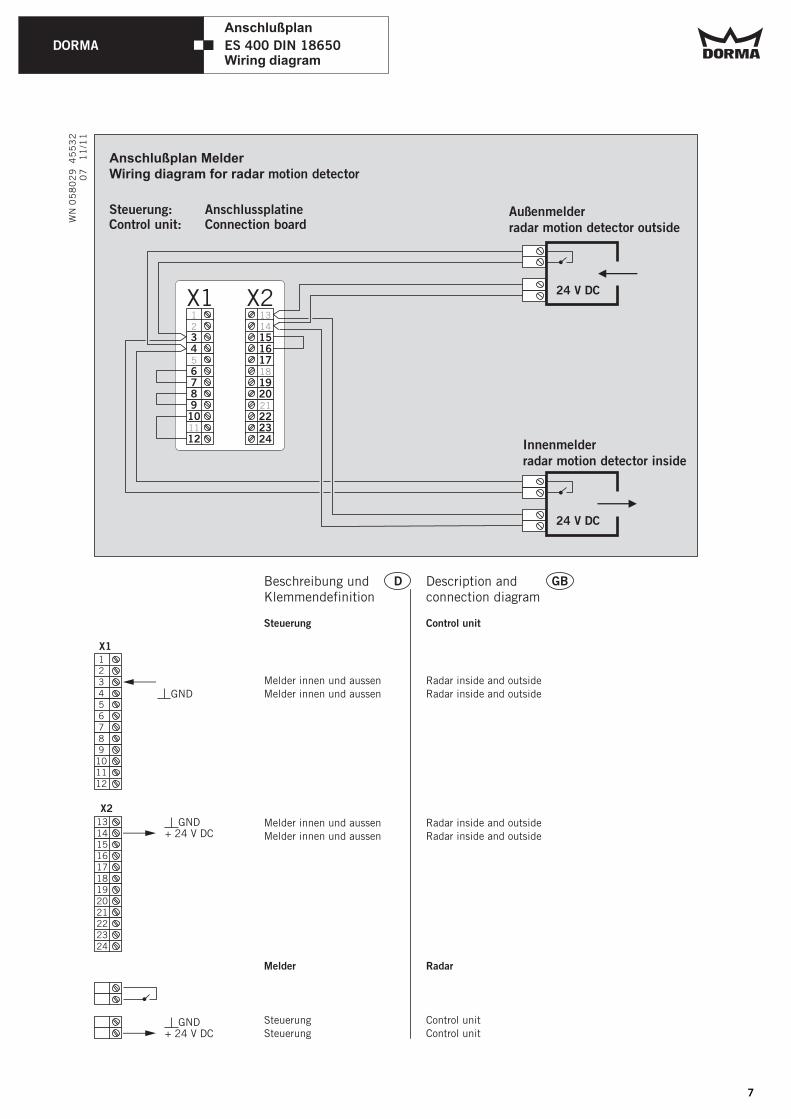
Innenmelderradar motion detector inside
Außenmelderradar motion detector outside
Anschlußplan Melder Wiring diagram for radar motion detector Plan de raccord pour le radar
Steuerung: AnschlussplatineControl unit: Connection board
X1
131415161718192021222324
D GBBeschreibung und Klemmendefinition
Description and connection diagram
GND+ 24 V DC
X2
GND
Steuerung Control unit
Melder Radar
GND+ 24 V DC
Melder innen und aussen
Melder innen und aussen
Radar inside and outside
Radar inside and outside
Melder innen und aussen
Melder innen und aussen
Radar inside and outside
Radar inside and outside
Steuerung
Steuerung
Control unit
Control unit
123456789
101112
24 V DC
24 V DC
ES 400 DIN 18650
Anschlußplan
Wiring diagram
7
DORMA
WN
05
80
29
4
55
32
11
/11
X2X1
1718192021222324
13141516
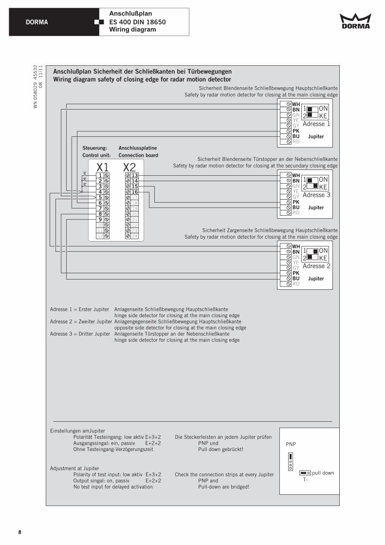
Anschlußplan Sicherheit der Schließkanten bei Türbewegungen Wiring diagram safety of closing edge for radar motion detector Plan de raccord pour le radar
Steuerung: Anschlussplatine
Control unit: Connection board
101112
123456789
12Adresse 1
ONKE
12Adresse 3
ONKE
12Adresse 2
ONKE
WHBN
PKBU
GNYEGY
RD
WHBN
PKBU
GNYEGY
RD
WHBN
PKBU
GNYEGY
RD
Die Steckerleisten an jedem Jupiter prüfenPNP und Pull down gebrückt!
PNP
pull down
T-
Sicherheit Schließbewegung Hauptschließkante
Safety by radar motion detector for closing at the main closing edge
Blendenseite
Sicherheit
Safety by radar motion detector for closing at the secundary closing edge
Blendenseite Türstopper an der Nebenschließkante
Jupiter
Jupiter
Jupiter
Sicherheit Schließbewegung Hauptschließkante
Safety by radar motion detector for closing at the main closing edge
Zargenseite
Adresse 1 = Erster Jupiterhinge side detector for closing at the main closing edge
Adresse 2 = Zweiter Jupiter Anlagengegenseite Schließbewegung Hauptschließkanteopposite side detector for closing at the main closing edge
Adresse 3 = Dritter Jupiter Anlagenseite Türstopper an der Nebenschließkantehinge side detector for closing at the main closing edge
Anlagenseite Schließbewegung Hauptschließkante
08
ES 400 DIN 18650
Anschlußplan
Wiring diagram
Einstellungen amJupiterPolarität Testeingang: low aktiv E+3+2Ausgangssingal: ein, passiv E+2+2Ohne Testeingang-Verzögerungszeit
Adjustment at JupiterPolarity of test input: low aktiv E+3+2Output singal: on, passiv E+2+2No test input for delayed activation
Check the connection strips at every JupiterPNP and Pull-down are bridged!
DORMA
WN
05
80
29
4
55
32
11
/11
09
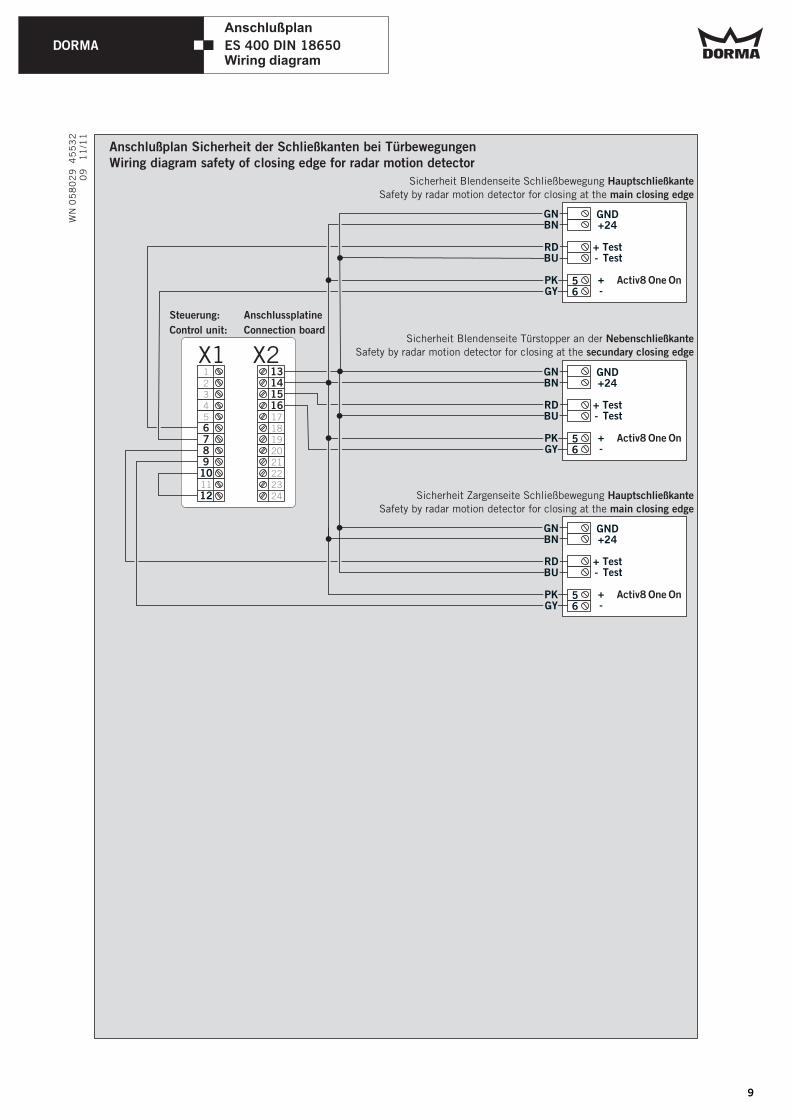
ES 400 DIN 18650
Anschlußplan
Wiring diagram
X2X1
1718192021222324
13141516
Anschlußplan Sicherheit der Schließkanten bei Türbewegungen Wiring diagram safety of closing edge for radar motion detector Plan de raccord pour le radar
Steuerung: Anschlussplatine
Control unit: Connection board
12345
11
6789
10
12
Sicherheit Schließbewegung Hauptschließkante
Safety by radar motion detector for closing at the main closing edge
Blendenseite
Sicherheit Nebenschließkante
Safety by radar motion detector for closing at the secundary closing edge
Blendenseite Türstopper an der
Sicherheit Schließbewegung Hauptschließkante
Safety by radar motion detector for closing at the main closing edge
Zargenseite
GNBN
RDBU
PKGY
GNBN
RDBU
PKGY
Activ8 One On56
GNBN
RDBU
PKGY
GNBN
RDBU
PKGY
Activ8 One On56
GND+24
+ Test
Test
+ -
-
AA
-
GND+24
+ Test Test
+ -
-
AA
-
GNBN
RDBU
PKGY
GNBN
RDBU
PKGY
Activ8 One On56
GND+24
+ Test Test
+ -
-
AA
-
9
DORMA
WN
05
80
29
4
55
32
11
/11
10
ES 400 DIN 18650
Anschlußplan
Wiring diagram
X2X1
1718192021222324
13141516
Steuerung: Anschlussplatine
Control unit: Connection board
12345
11
6789
10
12
Sicherheit Schließbewegung Hauptschließkante
Safety by radar motion detector for closing at the main closing edge
Blendenseite
Sicherheit Nebenschließkante
Safety by radar motion detector for closing at the secundary closing edge
Blendenseite Türstopper an der
Sicherheit Schließbewegung Hauptschließkante
Safety by radar motion detector for closing at the main closing edge
Zargenseite
GNBN
RDBU
PKGY
GNBN
RDBU
PKGY
56
GNBN
RDBU
PKGY
GNBN
RDBU
PKGY
56
GND+24
+ Test
Test
+ -
-
AA
-
GND+24
+ Test Test
+ -
-
AA
-
GNBN
RDBU
PKGY
GNBN
RDBU
PKGY
56
GND+24
+ Test Test
+ -
-
AA
-
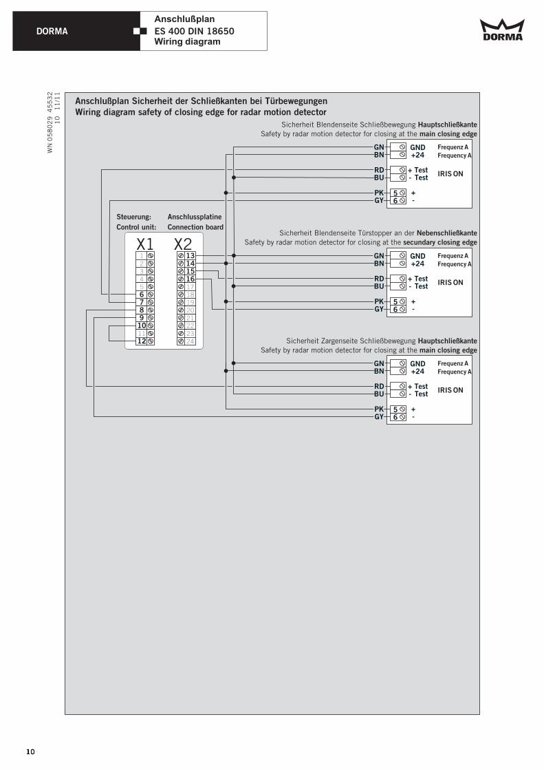
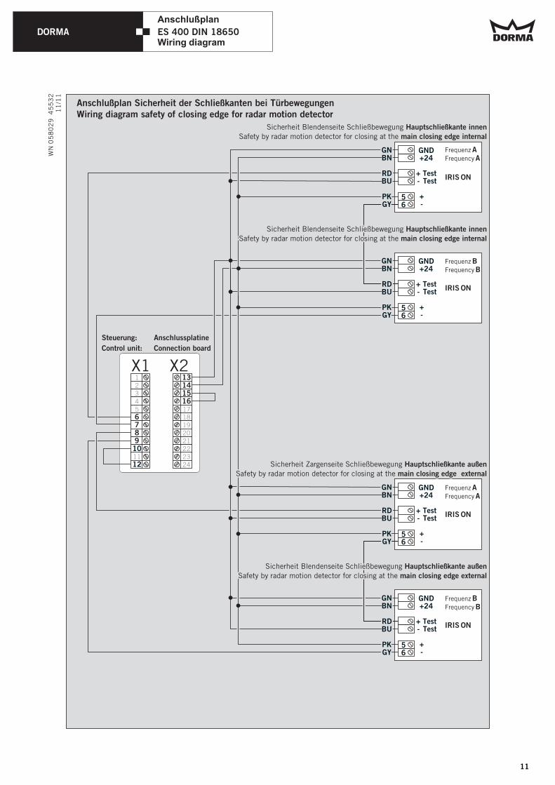
Anschlußplan Sicherheit der Schließkanten bei Türbewegungen Wiring diagram safety of closing edge for radar motion detector Plan de raccord pour le radar
IRIS ON
IRIS ON
IRIS ON
Frequenz A
Frequency A
Frequenz A
Frequency A
Frequenz A
Frequency A
DORMA
WN
05
80
29
4
55
32
11
/11
Anschlußplan Sicherheit der Schließkanten bei Türbewegungen Wiring diagram safety of closing edge for radar motion detector Plan de raccord pour le radar
X2X1
1718192021222324
13141516
Steuerung: Anschlussplatine
Control unit: Connection board
12345
11
6789
10
12
Sicherheit Schließbewegung Hauptschließkante innen
Safety by radar motion detector for closing at the main closing edge internal
Blendenseite
56
GND+24
+ Test Test
+ -
-
AA
-IRIS ON
Frequenz BFrequency B
56
GND+24
+ Test Test
+ -
-
AA
-IRIS ON
Frequenz AFrequency A
GNBN
RDBU
PKGY
GNBN
RDBU
PKGY
Sicherheit Blendenseite Schließbewegung Hauptschließkante außen
Safety by radar motion detector for closing at the main closing edge external
Sicherheit Blendenseite Schließbewegung Hauptschließkante außen
Safety by radar motion detector for closing at the main closing edge external
GNBN
RDBU
PKGY
GNBN
RDBU
PKGY
GNBN
RDBU
PKGY
GNBN
RDBU
PKGY
Sicherheit Blendenseite Schließbewegung Hauptschließkante innen
Safety by radar motion detector for closing at the main closing edge internal
Sicherheit Blendenseite Schließbewegung Hauptschließkante innen
Safety by radar motion detector for closing at the main closing edge internal
GNBN
RDBU
PKGY
GNBN
RDBU
PKGY
Sicherheit Zargenseite Schließbewegung Hauptschließkante außen
Safety by radar motion detector for closing at the main closing edge external
Sicherheit Zargenseite Schließbewegung Hauptschließkante außen
Safety by radar motion detector for closing at the main closing edge external
IRIS ON
56
56
GND+24
+ Test
Test
+ -
-
AA
-
GND+24
+ Test Test
+ -
-
AA
-IRIS ON
Frequenz AFrequency A
Frequenz BFrequency B
ES 400 DIN 18650
Anschlußplan
Wiring diagram
11
DORMA
WN
05
80
29
4
55
32
11
/11
X2X112345
11
6789
10
12
1314
1718192021222324
1516
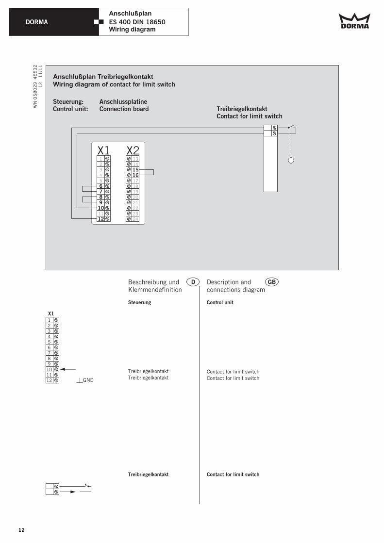
Anschlußplan TreibriegelkontaktWiring diagram of contact for limit switch
TreibriegelkontaktContact for limit switch
X1
GND
DBeschreibung und Klemmendefinition
Steuerung
Treibriegelkontakt
Treibriegelkontakt
Treibriegelkontakt
123456789
101112
GBDescription and connections diagram
Control unit
Contact for limit switch
Contact for limit switch
Contact for limit switch
Steuerung: AnschlussplatineControl unit: Connection board
12
ES 400 DIN 18650
Anschlußplan
Wiring diagram

DORMA
Drucktechnisch bedingte leere Seite Blank page on account of printing technology
13

www.dorma.com
DORMA GmbH + Co. KGDORMA Platz 1
D-58256 Ennepetal
Tel. +49 2333/793-0
Fax +49 2333/793-495005
8 0
29
45
53
2 1
1/1
1, Ä
nder
unge
n v
orbeh
alte
n
Subje
ct t
o ch
ange
wit
hou
t not
ice


![Chapter 29: City of Cape Town Events Policy · CITY OF CAPE TOWN EVENTS POLICY (POLICY NUMBER 12329) [REPLACES PREVIOUS EVENTS POLICY APPROVED ON 29 OCTOBER 2008] APPROVED BY COUNCIL](https://img.pdfslide.us/doc/110x75/5f6b923bbf010902f7043242/chapter-29-city-of-cape-town-events-policy-city-of-cape-town-events-policy-policy.jpg)