Embed Size (px)
Citation preview
LANCER RESERVES THE RIGHT TO MAKE ANY CHANGES IN THE MANUALS IN ORDER TO IMPROVE THEM.
INSTALLATION AND USER’S MANUAL
810 LX / 815 LX


INSTALLATION MANUAL810 LX / 815 LX

810-815 LX / INSTALLATION
NI_810-815_LX_PILOTE_ANG_A.doc 5
UNPACKAGING AND SETTING IN PLACE
• Remove the box and the plastic film from around the washer.
• Open the door of the washer by pulling the handle towards you and then lower thedoor to the horizontal position. Remove and inspect the contents of the washer andthen close the door by raising it and pressing on the handle.
• Put the feet washers in their location.
• Level the washer by adjusting the four heightadjustable feet.
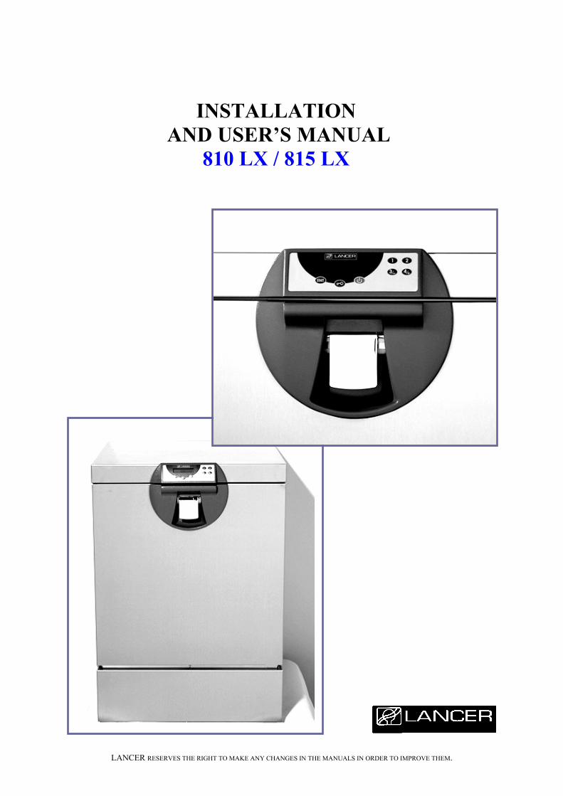
• Move the washer to where it will be used.
To move the washer put your hands on each side ofthe top cover. The washer can be pushed or pulledinto position by sliding it on the feet.
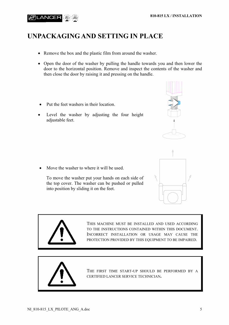
THIS MACHINE MUST BE INSTALLED AND USED ACCORDINGTO THE INSTRUCTIONS CONTAINED WITHIN THIS DOCUMENT.INCORRECT INSTALLATION OR USAGE MAY CAUSE THEPROTECTION PROVIDED BY THIS EQUIPMENT TO BE IMPAIRED.
THE FIRST TIME START-UP SHOULD BE PERFORMED BY ACERTIFIED LANCER SERVICE TECHNICIAN.
810-815 LX / INSTALLATION
NI_810-815_LX_PILOTE_ANG_A.doc 6
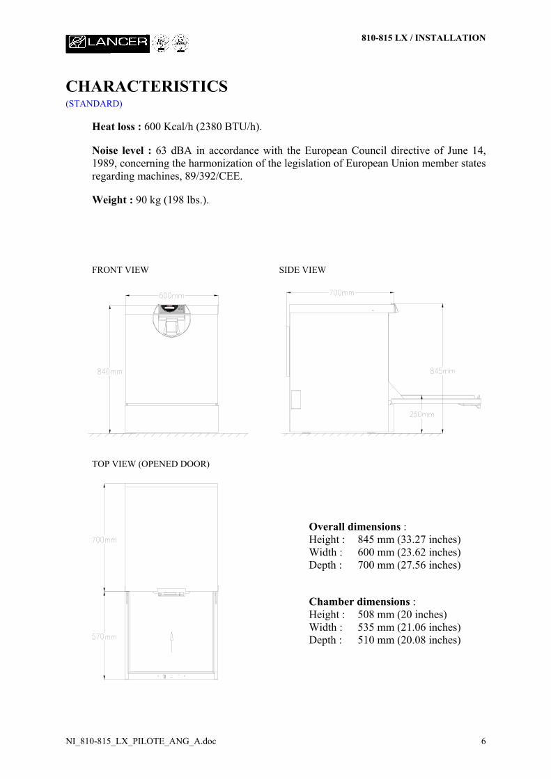
CHARACTERISTICS(STANDARD)
Heat loss : 600 Kcal/h (2380 BTU/h).
Noise level : 63 dBA in accordance with the European Council directive of June 14,1989, concerning the harmonization of the legislation of European Union member statesregarding machines, 89/392/CEE.
Weight : 90 kg (198 lbs.).
FRONT VIEW SIDE VIEW
TOP VIEW (OPENED DOOR)
Overall dimensions :Height : 845 mm (33.27 inches)Width : 600 mm (23.62 inches)Depth : 700 mm (27.56 inches)
Chamber dimensions :Height : 508 mm (20 inches)Width : 535 mm (21.06 inches)Depth : 510 mm (20.08 inches)
810-815 LX / INSTALLATION
NI_810-815_LX_PILOTE_ANG_A.doc 7
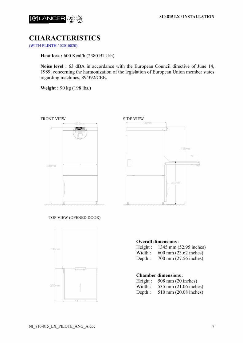
CHARACTERISTICS(WITH PLINTH / 02010020)
Heat loss : 600 Kcal/h (2380 BTU/h).
Noise level : 63 dBA in accordance with the European Council directive of June 14,1989, concerning the harmonization of the legislation of European Union member statesregarding machines, 89/392/CEE.
Weight : 90 kg (198 lbs.)
FRONT VIEW SIDE VIEW
TOP VIEW (OPENED DOOR)
Overall dimensions :Height : 1345 mm (52.95 inches)Width : 600 mm (23.62 inches)Depth : 700 mm (27.56 inches)
Chamber dimensions :Height : 508 mm (20 inches)Width : 535 mm (21.06 inches)Depth : 510 mm (20.08 inches)
810-815 LX / INSTALLATION
NI_810-815_LX_PILOTE_ANG_A.doc 8
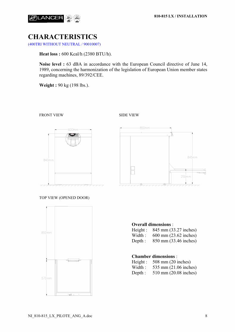
CHARACTERISTICS(400TRI WITHOUT NEUTRAL / 90010007)
Heat loss : 600 Kcal/h (2380 BTU/h).
Noise level : 63 dBA in accordance with the European Council directive of June 14,1989, concerning the harmonization of the legislation of European Union member statesregarding machines, 89/392/CEE.
Weight : 90 kg (198 lbs.).
FRONT VIEW SIDE VIEW
TOP VIEW (OPENED DOOR)
Overall dimensions :Height : 845 mm (33.27 inches)Width : 600 mm (23.62 inches)Depth : 850 mm (33.46 inches)
Chamber dimensions :Height : 508 mm (20 inches)Width : 535 mm (21.06 inches)Depth : 510 mm (20.08 inches)

810-815 LX / INSTALLATION
NI_810-815_LX_PILOTE_ANG_A.doc 9
CHARACTERISTICS(400 WITHOUT NEUTRAL - WITH PLINTH / 90010007 + 02010020)
Heat loss : 600 Kcal/h (2380 BTU/h).
Noise level : 63 dBA in accordance with the European Council directive of June 14,1989, concerning the harmonization of the legislation of European Union member statesregarding machines, 89/392/CEE.
Weight : 90 kg (198 lbs.)
FRONT VIEW SIDE VIEW
TOP VIEW (OPENED DOOR)
Overall dimensions :Height : 1345 mm (52.95 inches)Width : 600 mm (23.62 inches)Depth : 850 mm (33.46 inches)
Chamber dimensions :Height : 508 mm (20 inches)Width : 535 mm (21.06 inches)Depth : 510 mm (20.08 inches)
810-815 LX / INSTALLATION
NI_810-815_LX_PILOTE_ANG_A.doc 10
OPERATING ENVIRONMENT
The washer is designed for use in the following conditions :
• AN INDOOR ENVIRONMENT.
• ALTITUDE UP TO 2000 METERS (6,562 FEET).
• TEMPERATURE BETWEEN 5°C AND 40°C (41°F AND 104°F).
• MAXIMUM RELATIVE HUMIDITY OF 80% UP TO 31°C (88°F)DECREASING LINEARLY TO 50% RELATIVE HUMIDITY AT 40°C(104°F).
810-815 LX / INSTALLATION
NI_810-815_LX_PILOTE_ANG_A.doc 11
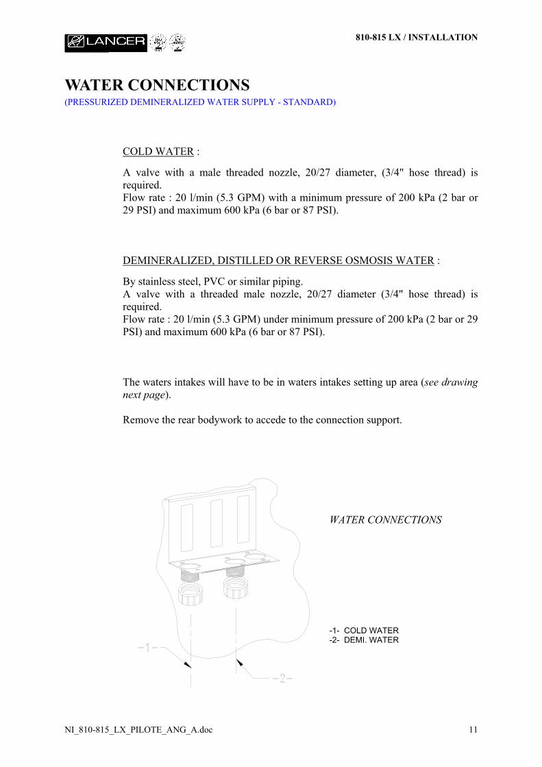
WATER CONNECTIONS(PRESSURIZED DEMINERALIZED WATER SUPPLY - STANDARD)
COLD WATER :
A valve with a male threaded nozzle, 20/27 diameter, (3/4" hose thread) isrequired.Flow rate : 20 l/min (5.3 GPM) with a minimum pressure of 200 kPa (2 bar or29 PSI) and maximum 600 kPa (6 bar or 87 PSI).
DEMINERALIZED, DISTILLED OR REVERSE OSMOSIS WATER :
By stainless steel, PVC or similar piping.A valve with a threaded male nozzle, 20/27 diameter (3/4" hose thread) isrequired.Flow rate : 20 l/min (5.3 GPM) under minimum pressure of 200 kPa (2 bar or 29PSI) and maximum 600 kPa (6 bar or 87 PSI).
The waters intakes will have to be in waters intakes setting up area (see drawingnext page).
Remove the rear bodywork to accede to the connection support.
WATER CONNECTIONS
-1- COLD WATER-2- DEMI. WATER
810-815 LX / INSTALLATION
NI_810-815_LX_PILOTE_ANG_A.doc 12
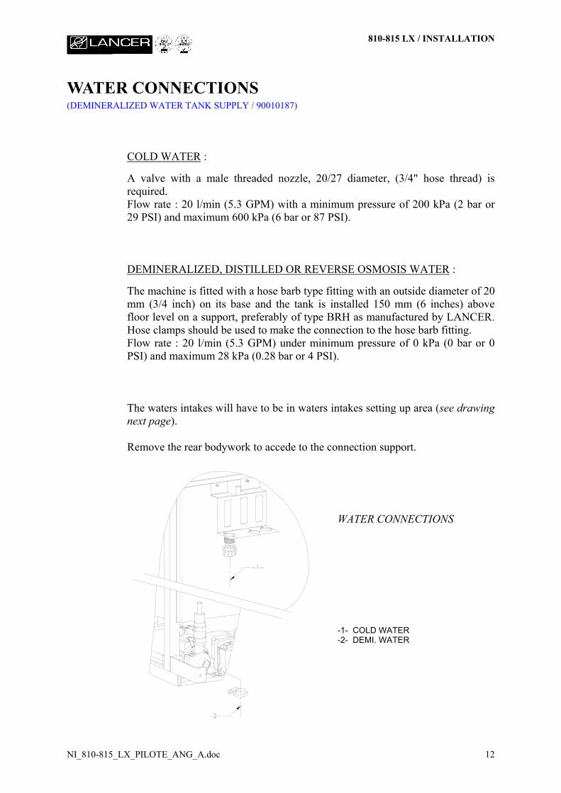
WATER CONNECTIONS(DEMINERALIZED WATER TANK SUPPLY / 90010187)
COLD WATER :
A valve with a male threaded nozzle, 20/27 diameter, (3/4" hose thread) isrequired.Flow rate : 20 l/min (5.3 GPM) with a minimum pressure of 200 kPa (2 bar or29 PSI) and maximum 600 kPa (6 bar or 87 PSI).
DEMINERALIZED, DISTILLED OR REVERSE OSMOSIS WATER :
The machine is fitted with a hose barb type fitting with an outside diameter of 20mm (3/4 inch) on its base and the tank is installed 150 mm (6 inches) abovefloor level on a support, preferably of type BRH as manufactured by LANCER.Hose clamps should be used to make the connection to the hose barb fitting.Flow rate : 20 l/min (5.3 GPM) under minimum pressure of 0 kPa (0 bar or 0PSI) and maximum 28 kPa (0.28 bar or 4 PSI).
The waters intakes will have to be in waters intakes setting up area (see drawingnext page).
Remove the rear bodywork to accede to the connection support.
WATER CONNECTIONS
-1- COLD WATER-2- DEMI. WATER
810-815 LX / INSTALLATION
NI_810-815_LX_PILOTE_ANG_A.doc 13
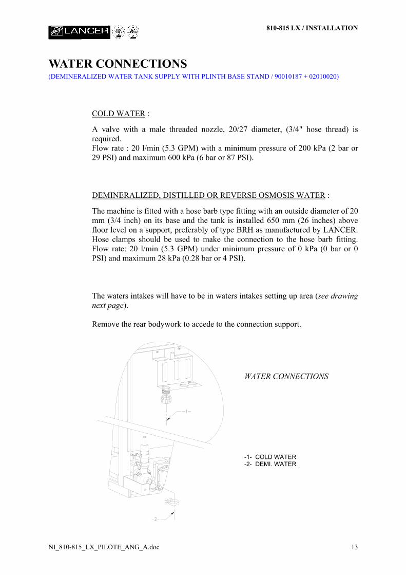
WATER CONNECTIONS(DEMINERALIZED WATER TANK SUPPLY WITH PLINTH BASE STAND / 90010187 + 02010020)
COLD WATER :
A valve with a male threaded nozzle, 20/27 diameter, (3/4" hose thread) isrequired.Flow rate : 20 l/min (5.3 GPM) with a minimum pressure of 200 kPa (2 bar or29 PSI) and maximum 600 kPa (6 bar or 87 PSI).
DEMINERALIZED, DISTILLED OR REVERSE OSMOSIS WATER :
The machine is fitted with a hose barb type fitting with an outside diameter of 20mm (3/4 inch) on its base and the tank is installed 650 mm (26 inches) abovefloor level on a support, preferably of type BRH as manufactured by LANCER.Hose clamps should be used to make the connection to the hose barb fitting.Flow rate: 20 l/min (5.3 GPM) under minimum pressure of 0 kPa (0 bar or 0PSI) and maximum 28 kPa (0.28 bar or 4 PSI).
The waters intakes will have to be in waters intakes setting up area (see drawingnext page).
Remove the rear bodywork to accede to the connection support.
WATER CONNECTIONS
-1- COLD WATER-2- DEMI. WATER
810-815 LX / INSTALLATION
NI_810-815_LX_PILOTE_ANG_A.doc 14
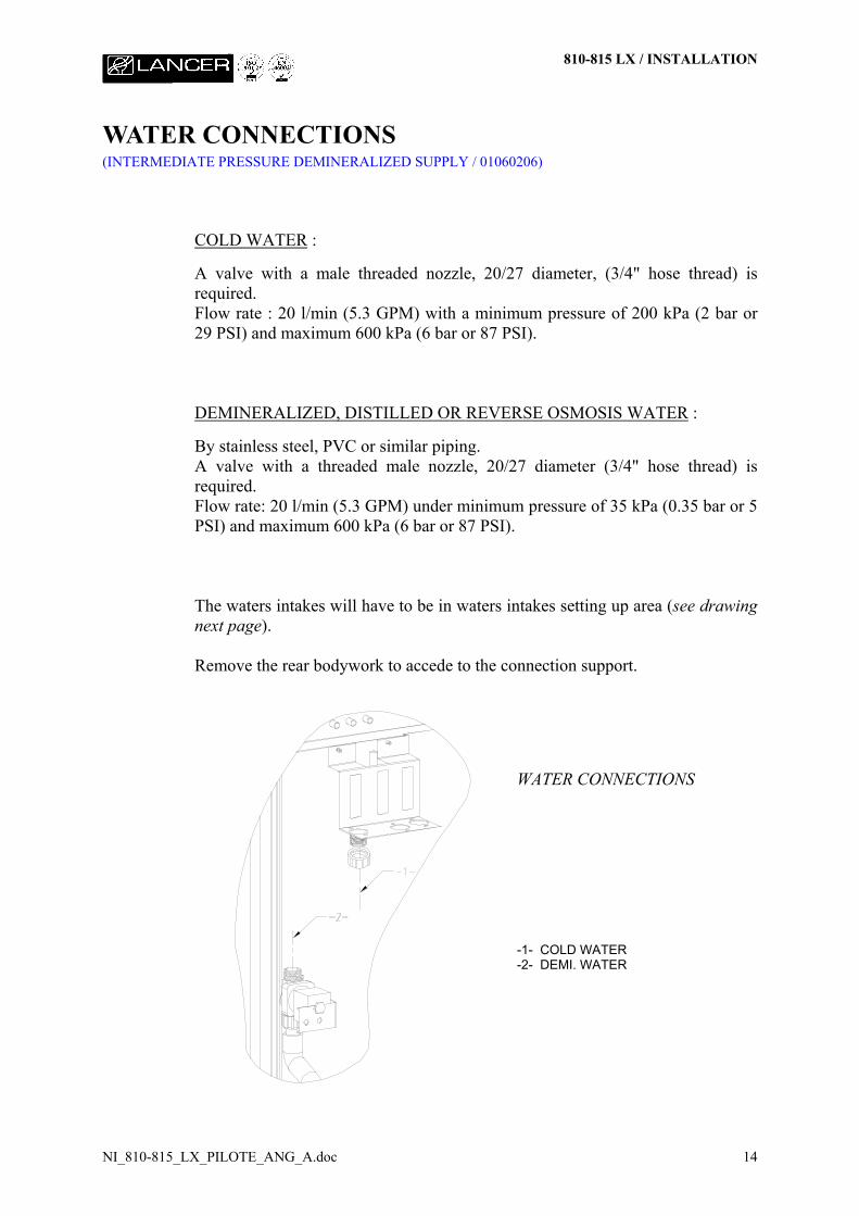
WATER CONNECTIONS(INTERMEDIATE PRESSURE DEMINERALIZED SUPPLY / 01060206)
COLD WATER :
A valve with a male threaded nozzle, 20/27 diameter, (3/4" hose thread) isrequired.Flow rate : 20 l/min (5.3 GPM) with a minimum pressure of 200 kPa (2 bar or29 PSI) and maximum 600 kPa (6 bar or 87 PSI).
DEMINERALIZED, DISTILLED OR REVERSE OSMOSIS WATER :
By stainless steel, PVC or similar piping.A valve with a threaded male nozzle, 20/27 diameter (3/4" hose thread) isrequired.Flow rate: 20 l/min (5.3 GPM) under minimum pressure of 35 kPa (0.35 bar or 5PSI) and maximum 600 kPa (6 bar or 87 PSI).
The waters intakes will have to be in waters intakes setting up area (see drawingnext page).
Remove the rear bodywork to accede to the connection support.
WATER CONNECTIONS
-1- COLD WATER-2- DEMI. WATER
810-815 LX / INSTALLATION
NI_810-815_LX_PILOTE_ANG_A.doc 15
DRAIN DISCHARGE COOLING WATER : (90010077)
Utilizes the COLD WATER valve as specified above. Cold water source shouldbe less than 25°C.
CONDENSER : (90010078)
Utilizes the COLD WATER valve as specified above. Cold water source shouldbe less than 25°C.
810-815 LX / INSTALLATION
NI_810-815_LX_PILOTE_ANG_A.doc 16
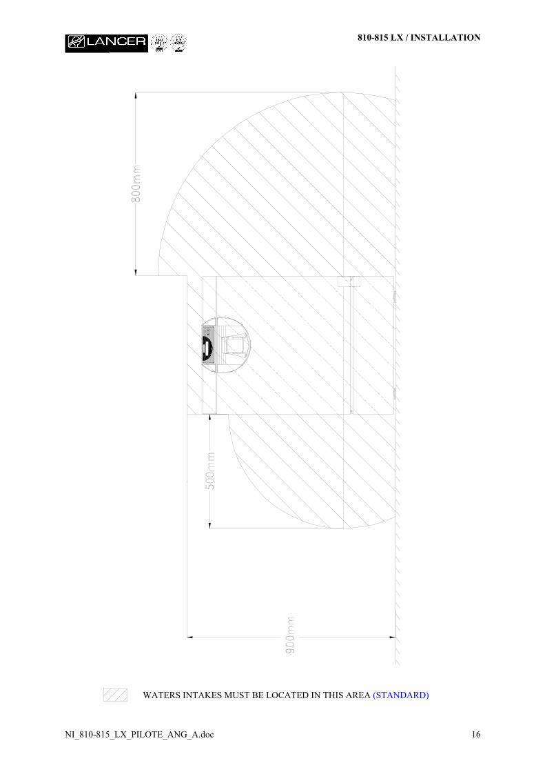
WATERS INTAKES MUST BE LOCATED IN THIS AREA (STANDARD)
810-815 LX / INSTALLATION
NI_810-815_LX_PILOTE_ANG_A.doc 17
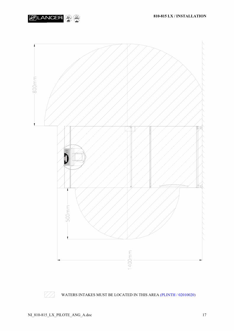
WATERS INTAKES MUST BE LOCATED IN THIS AREA (PLINTH / 02010020)
810-815 LX / INSTALLATION
NI_810-815_LX_PILOTE_ANG_A.doc 18
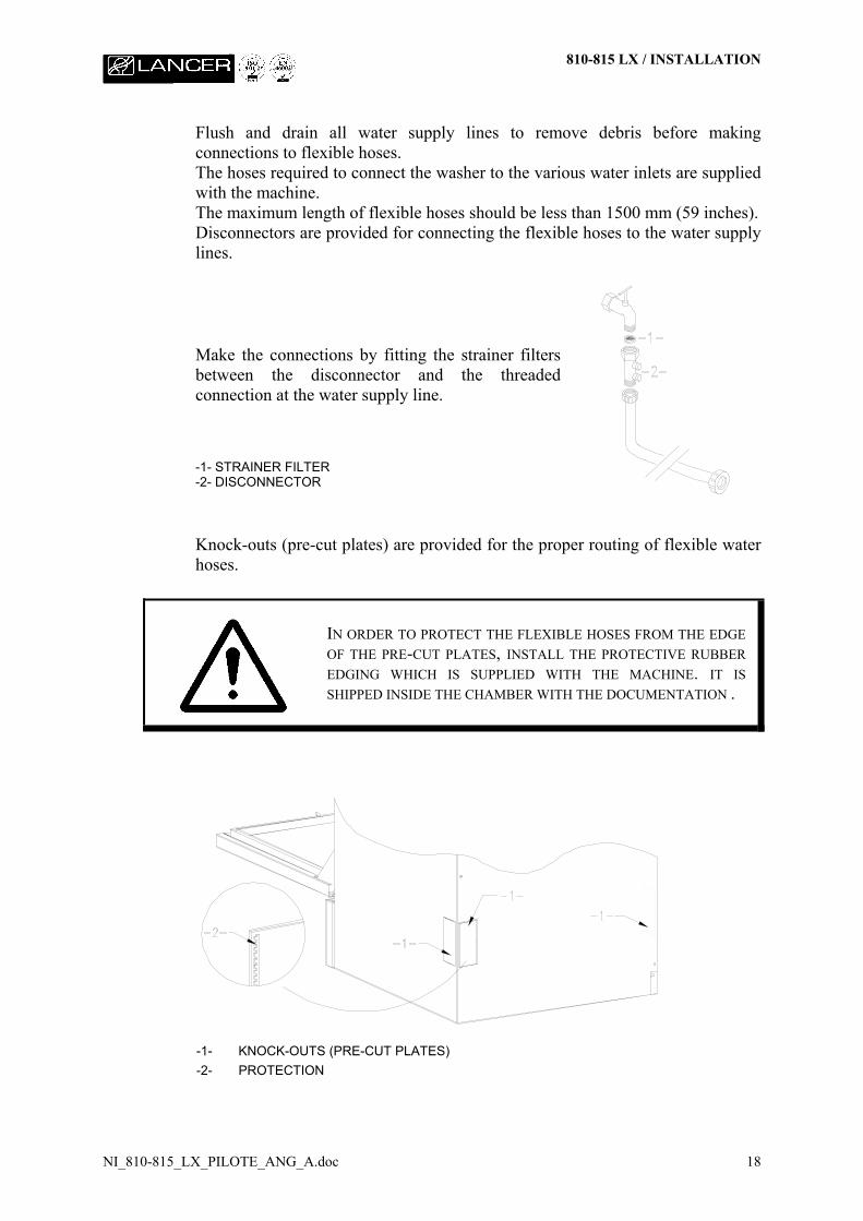
Flush and drain all water supply lines to remove debris before makingconnections to flexible hoses.The hoses required to connect the washer to the various water inlets are suppliedwith the machine.The maximum length of flexible hoses should be less than 1500 mm (59 inches).Disconnectors are provided for connecting the flexible hoses to the water supplylines.
Make the connections by fitting the strainer filtersbetween the disconnector and the threadedconnection at the water supply line.
-1- STRAINER FILTER-2- DISCONNECTOR
Knock-outs (pre-cut plates) are provided for the proper routing of flexible waterhoses.
IN ORDER TO PROTECT THE FLEXIBLE HOSES FROM THE EDGEOF THE PRE-CUT PLATES, INSTALL THE PROTECTIVE RUBBEREDGING WHICH IS SUPPLIED WITH THE MACHINE. IT ISSHIPPED INSIDE THE CHAMBER WITH THE DOCUMENTATION .
-1- KNOCK-OUTS (PRE-CUT PLATES)-2- PROTECTION
810-815 LX / INSTALLATION
NI_810-815_LX_PILOTE_ANG_A.doc 19
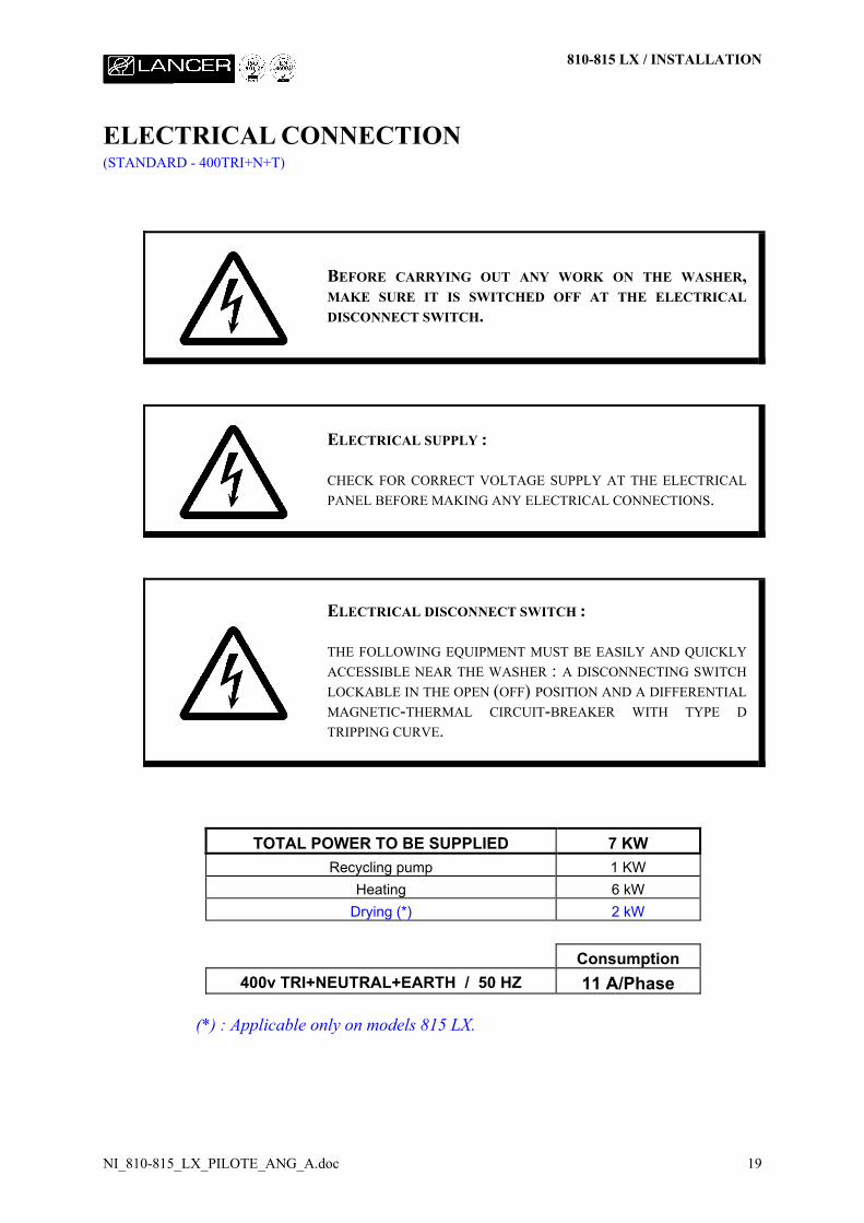
ELECTRICAL CONNECTION(STANDARD - 400TRI+N+T)
BEFORE CARRYING OUT ANY WORK ON THE WASHER,MAKE SURE IT IS SWITCHED OFF AT THE ELECTRICALDISCONNECT SWITCH.
ELECTRICAL SUPPLY :
CHECK FOR CORRECT VOLTAGE SUPPLY AT THE ELECTRICALPANEL BEFORE MAKING ANY ELECTRICAL CONNECTIONS.
ELECTRICAL DISCONNECT SWITCH :
THE FOLLOWING EQUIPMENT MUST BE EASILY AND QUICKLYACCESSIBLE NEAR THE WASHER : A DISCONNECTING SWITCHLOCKABLE IN THE OPEN (OFF) POSITION AND A DIFFERENTIALMAGNETIC-THERMAL CIRCUIT-BREAKER WITH TYPE DTRIPPING CURVE.
TOTAL POWER TO BE SUPPLIED 7 KWRecycling pump 1 KW
Heating 6 kWDrying (*) 2 kW
Consumption400v TRI+NEUTRAL+EARTH / 50 HZ 11 A/Phase
(*) : Applicable only on models 815 LX.
810-815 LX / INSTALLATION
NI_810-815_LX_PILOTE_ANG_A.doc 20
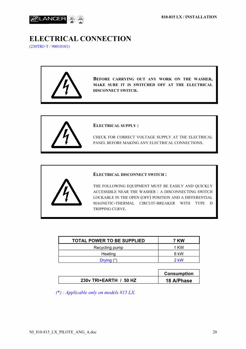
ELECTRICAL CONNECTION(230TRI+T / 90010101)
BEFORE CARRYING OUT ANY WORK ON THE WASHER,MAKE SURE IT IS SWITCHED OFF AT THE ELECTRICALDISCONNECT SWITCH.
ELECTRICAL SUPPLY :
CHECK FOR CORRECT VOLTAGE SUPPLY AT THE ELECTRICALPANEL BEFORE MAKING ANY ELECTRICAL CONNECTIONS.
ELECTRICAL DISCONNECT SWITCH :
THE FOLLOWING EQUIPMENT MUST BE EASILY AND QUICKLYACCESSIBLE NEAR THE WASHER : A DISCONNECTING SWITCHLOCKABLE IN THE OPEN (OFF) POSITION AND A DIFFERENTIALMAGNETIC-THERMAL CIRCUIT-BREAKER WITH TYPE DTRIPPING CURVE.
TOTAL POWER TO BE SUPPLIED 7 KWRecycling pump 1 KW
Heating 6 kWDrying (*) 2 kW
Consumption230v TRI+EARTH / 50 HZ 18 A/Phase
(*) : Applicable only on models 815 LX.
810-815 LX / INSTALLATION
NI_810-815_LX_PILOTE_ANG_A.doc 21
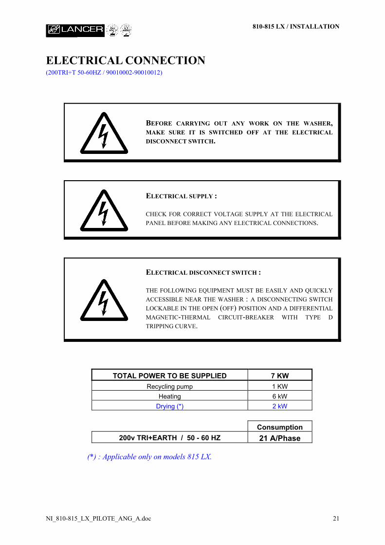
ELECTRICAL CONNECTION(200TRI+T 50-60HZ / 90010002-90010012)
BEFORE CARRYING OUT ANY WORK ON THE WASHER,MAKE SURE IT IS SWITCHED OFF AT THE ELECTRICALDISCONNECT SWITCH.
ELECTRICAL SUPPLY :
CHECK FOR CORRECT VOLTAGE SUPPLY AT THE ELECTRICALPANEL BEFORE MAKING ANY ELECTRICAL CONNECTIONS.
ELECTRICAL DISCONNECT SWITCH :
THE FOLLOWING EQUIPMENT MUST BE EASILY AND QUICKLYACCESSIBLE NEAR THE WASHER : A DISCONNECTING SWITCHLOCKABLE IN THE OPEN (OFF) POSITION AND A DIFFERENTIALMAGNETIC-THERMAL CIRCUIT-BREAKER WITH TYPE DTRIPPING CURVE.
TOTAL POWER TO BE SUPPLIED 7 KWRecycling pump 1 KW
Heating 6 kWDrying (*) 2 kW
Consumption200v TRI+EARTH / 50 - 60 HZ 21 A/Phase
(*) : Applicable only on models 815 LX.

810-815 LX / INSTALLATION
NI_810-815_LX_PILOTE_ANG_A.doc 22
ELECTRICAL CONNECTION(230MONO+T / 90010100)
BEFORE CARRYING OUT ANY WORK ON THE WASHER,MAKE SURE IT IS SWITCHED OFF AT THE ELECTRICALDISCONNECT SWITCH.
ELECTRICAL SUPPLY :
CHECK FOR CORRECT VOLTAGE SUPPLY AT THE ELECTRICALPANEL BEFORE MAKING ANY ELECTRICAL CONNECTIONS.
ELECTRICAL DISCONNECT SWITCH :
THE FOLLOWING EQUIPMENT MUST BE EASILY AND QUICKLYACCESSIBLE NEAR THE WASHER : A DISCONNECTING SWITCHLOCKABLE IN THE OPEN (OFF) POSITION AND A DIFFERENTIALMAGNETIC-THERMAL CIRCUIT-BREAKER WITH TYPE DTRIPPING CURVE.
TOTAL POWER TO BE SUPPLIED 7 KWRecycling pump 1 KW
Heating 6 kWDrying (*) 2 kW
Consumption230v MONO+EARTH / 50 HZ 31 A/Phase
(*) : Applicable only on models 815 LX.
810-815 LX / INSTALLATION
NI_810-815_LX_PILOTE_ANG_A.doc 23
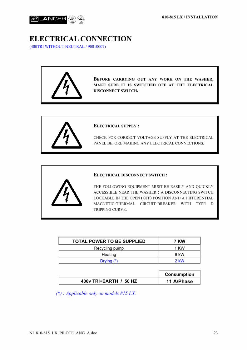
ELECTRICAL CONNECTION(400TRI WITHOUT NEUTRAL / 90010007)
BEFORE CARRYING OUT ANY WORK ON THE WASHER,MAKE SURE IT IS SWITCHED OFF AT THE ELECTRICALDISCONNECT SWITCH.
ELECTRICAL SUPPLY :
CHECK FOR CORRECT VOLTAGE SUPPLY AT THE ELECTRICALPANEL BEFORE MAKING ANY ELECTRICAL CONNECTIONS.
ELECTRICAL DISCONNECT SWITCH :
THE FOLLOWING EQUIPMENT MUST BE EASILY AND QUICKLYACCESSIBLE NEAR THE WASHER : A DISCONNECTING SWITCHLOCKABLE IN THE OPEN (OFF) POSITION AND A DIFFERENTIALMAGNETIC-THERMAL CIRCUIT-BREAKER WITH TYPE DTRIPPING CURVE.
TOTAL POWER TO BE SUPPLIED 7 KWRecycling pump 1 KW
Heating 6 kWDrying (*) 2 kW
Consumption400v TRI+EARTH / 50 HZ 11 A/Phase
(*) : Applicable only on models 815 LX.
810-815 LX / INSTALLATION
NI_810-815_LX_PILOTE_ANG_A.doc 24
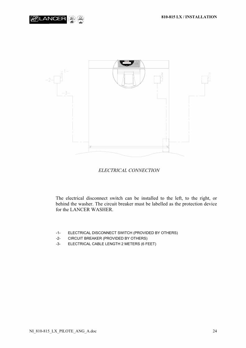
ELECTRICAL CONNECTION
The electrical disconnect switch can be installed to the left, to the right, orbehind the washer. The circuit breaker must be labelled as the protection devicefor the LANCER WASHER.
-1- ELECTRICAL DISCONNECT SWITCH (PROVIDED BY OTHERS)-2- CIRCUIT BREAKER (PROVIDED BY OTHERS)-3- ELECTRICAL CABLE LENGTH 2 METERS (6 FEET)
810-815 LX / INSTALLATION
NI_810-815_LX_PILOTE_ANG_A.doc 25
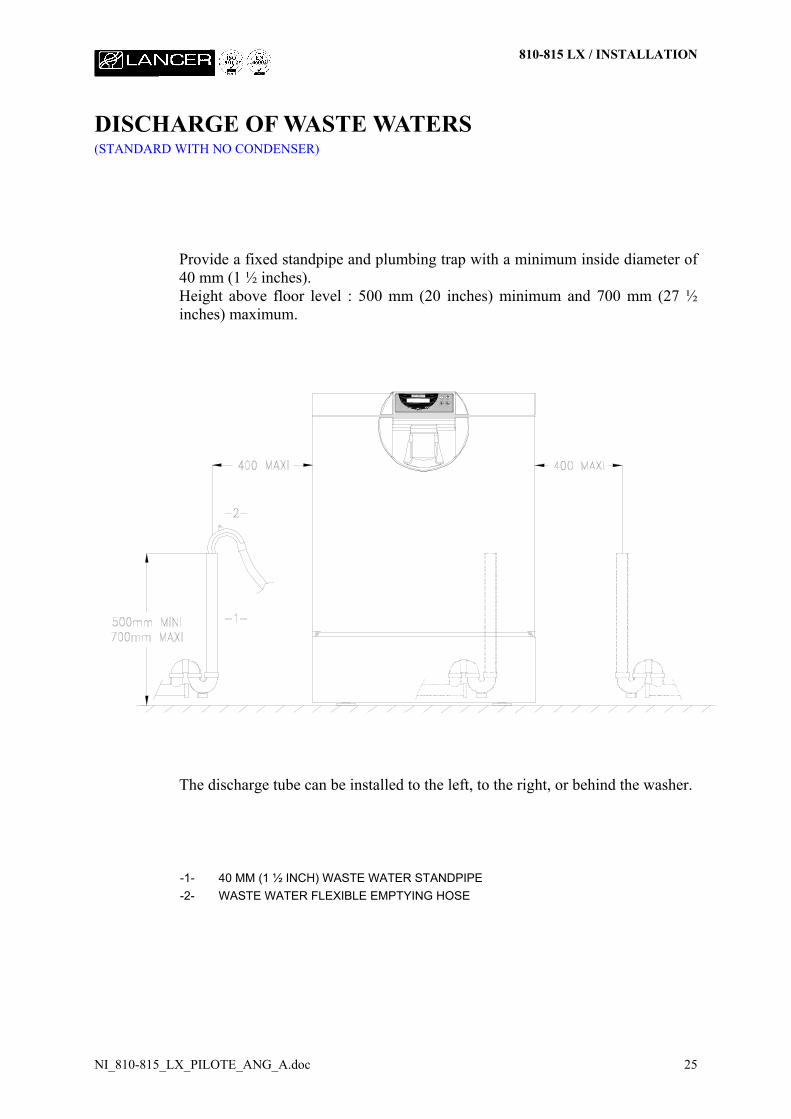
DISCHARGE OF WASTE WATERS(STANDARD WITH NO CONDENSER)
Provide a fixed standpipe and plumbing trap with a minimum inside diameter of40 mm (1 ½ inches).Height above floor level : 500 mm (20 inches) minimum and 700 mm (27 ½inches) maximum.
The discharge tube can be installed to the left, to the right, or behind the washer.
-1- 40 MM (1 ½ INCH) WASTE WATER STANDPIPE-2- WASTE WATER FLEXIBLE EMPTYING HOSE
810-815 LX / INSTALLATION
NI_810-815_LX_PILOTE_ANG_A.doc 26
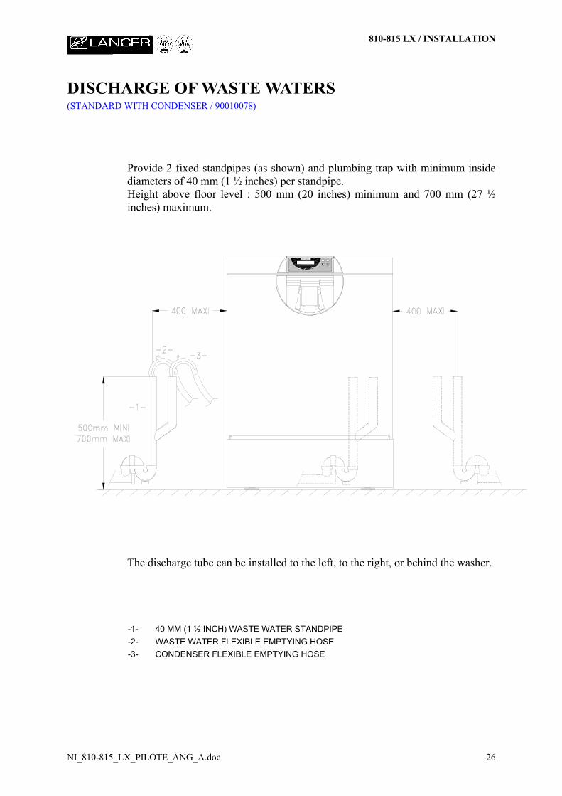
DISCHARGE OF WASTE WATERS(STANDARD WITH CONDENSER / 90010078)
Provide 2 fixed standpipes (as shown) and plumbing trap with minimum insidediameters of 40 mm (1 ½ inches) per standpipe.Height above floor level : 500 mm (20 inches) minimum and 700 mm (27 ½inches) maximum.
The discharge tube can be installed to the left, to the right, or behind the washer.
-1- 40 MM (1 ½ INCH) WASTE WATER STANDPIPE-2- WASTE WATER FLEXIBLE EMPTYING HOSE-3- CONDENSER FLEXIBLE EMPTYING HOSE
810-815 LX / INSTALLATION
NI_810-815_LX_PILOTE_ANG_A.doc 27
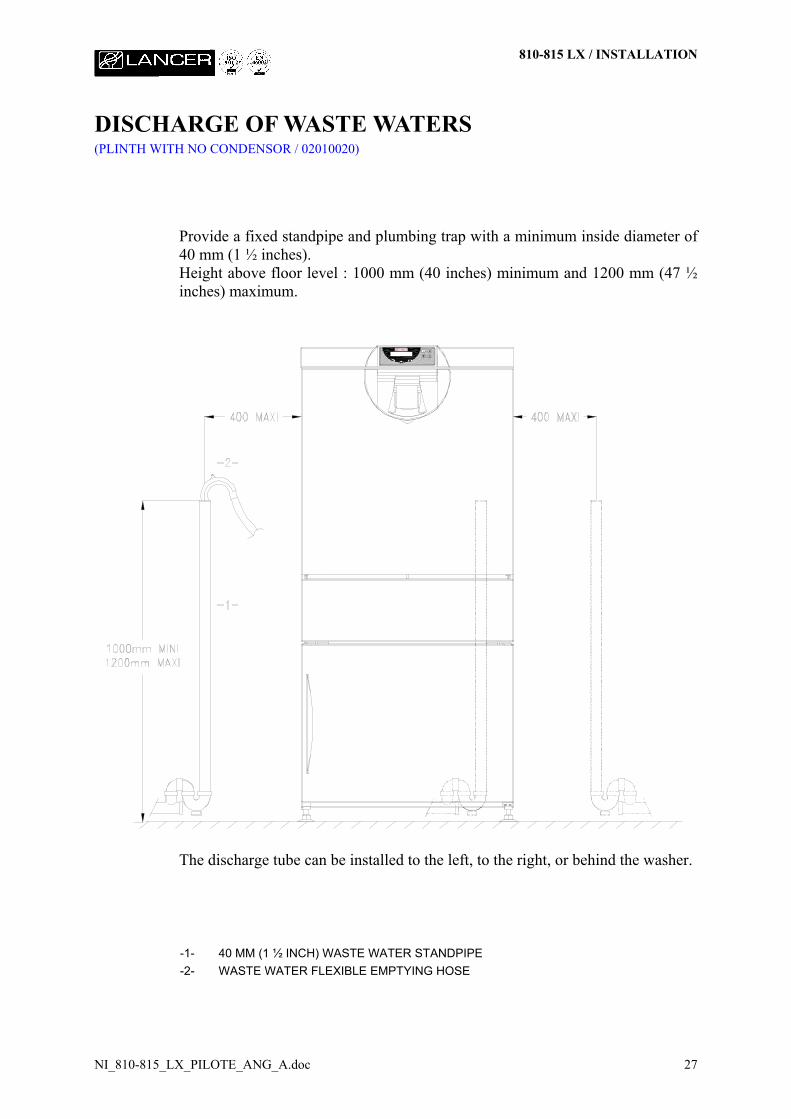
DISCHARGE OF WASTE WATERS(PLINTH WITH NO CONDENSOR / 02010020)
Provide a fixed standpipe and plumbing trap with a minimum inside diameter of40 mm (1 ½ inches).Height above floor level : 1000 mm (40 inches) minimum and 1200 mm (47 ½inches) maximum.
The discharge tube can be installed to the left, to the right, or behind the washer.
-1- 40 MM (1 ½ INCH) WASTE WATER STANDPIPE-2- WASTE WATER FLEXIBLE EMPTYING HOSE
810-815 LX / INSTALLATION
NI_810-815_LX_PILOTE_ANG_A.doc 28
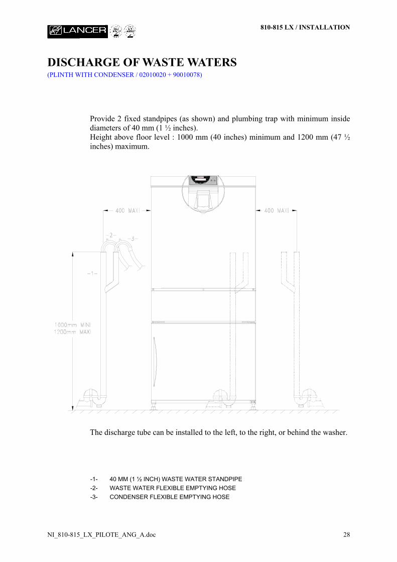
DISCHARGE OF WASTE WATERS(PLINTH WITH CONDENSER / 02010020 + 90010078)
Provide 2 fixed standpipes (as shown) and plumbing trap with minimum insidediameters of 40 mm (1 ½ inches).Height above floor level : 1000 mm (40 inches) minimum and 1200 mm (47 ½inches) maximum.
The discharge tube can be installed to the left, to the right, or behind the washer.
-1- 40 MM (1 ½ INCH) WASTE WATER STANDPIPE-2- WASTE WATER FLEXIBLE EMPTYING HOSE-3- CONDENSER FLEXIBLE EMPTYING HOSE
810-815 LX / INSTALLATION
NI_810-815_LX_PILOTE_ANG_A.doc 29
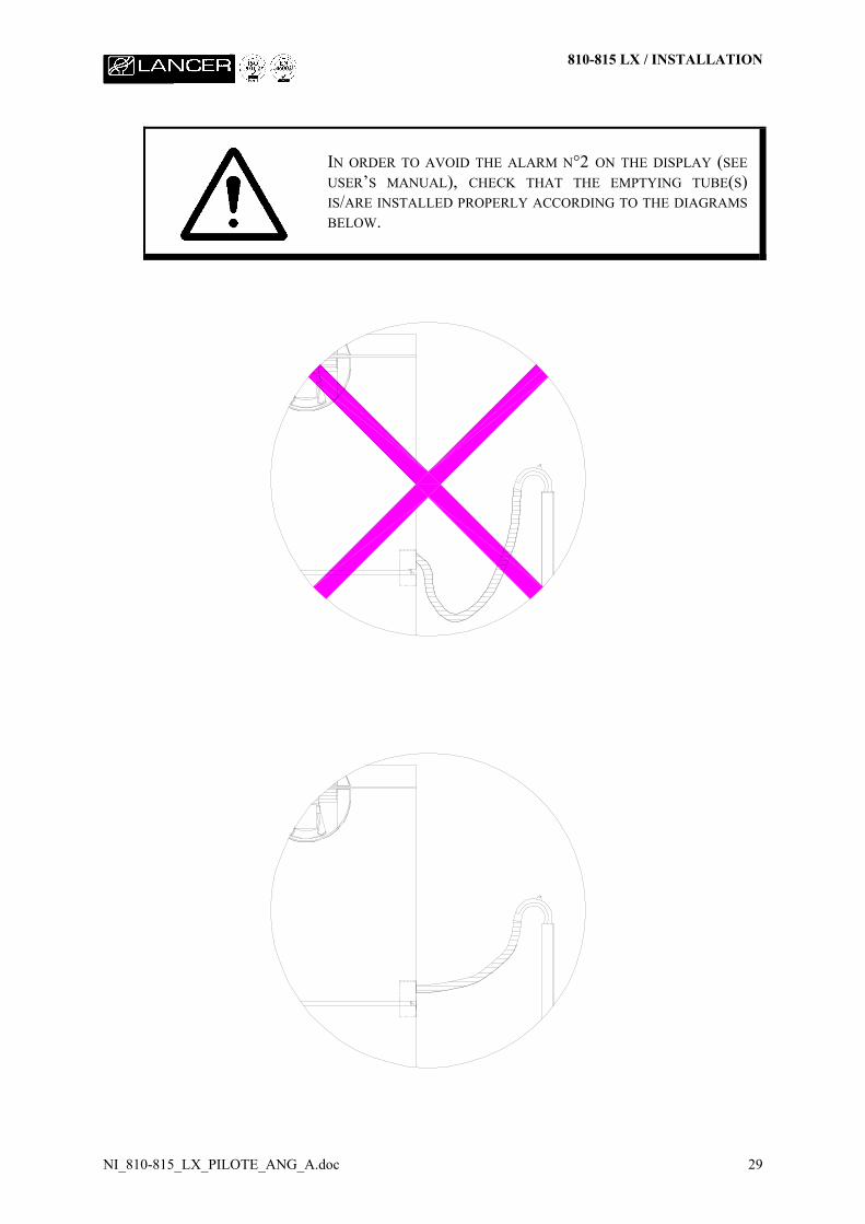
IN ORDER TO AVOID THE ALARM N°2 ON THE DISPLAY (SEEUSER’S MANUAL), CHECK THAT THE EMPTYING TUBE(S)IS/ARE INSTALLED PROPERLY ACCORDING TO THE DIAGRAMSBELOW.
810-815 LX / INSTALLATION
NI_810-815_LX_PILOTE_ANG_A.doc 30
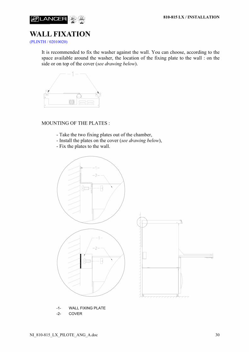
WALL FIXATION(PLINTH / 02010020)
It is recommended to fix the washer against the wall. You can choose, according to thespace available around the washer, the location of the fixing plate to the wall : on theside or on top of the cover (see drawing below).
MOUNTING OF THE PLATES :
- Take the two fixing plates out of the chamber,- Install the plates on the cover (see drawing below),- Fix the plates to the wall.
-1- WALL FIXING PLATE-2- COVER
810-815 LX / INSTALLATION
NI_810-815_LX_PILOTE_ANG_A.doc 31
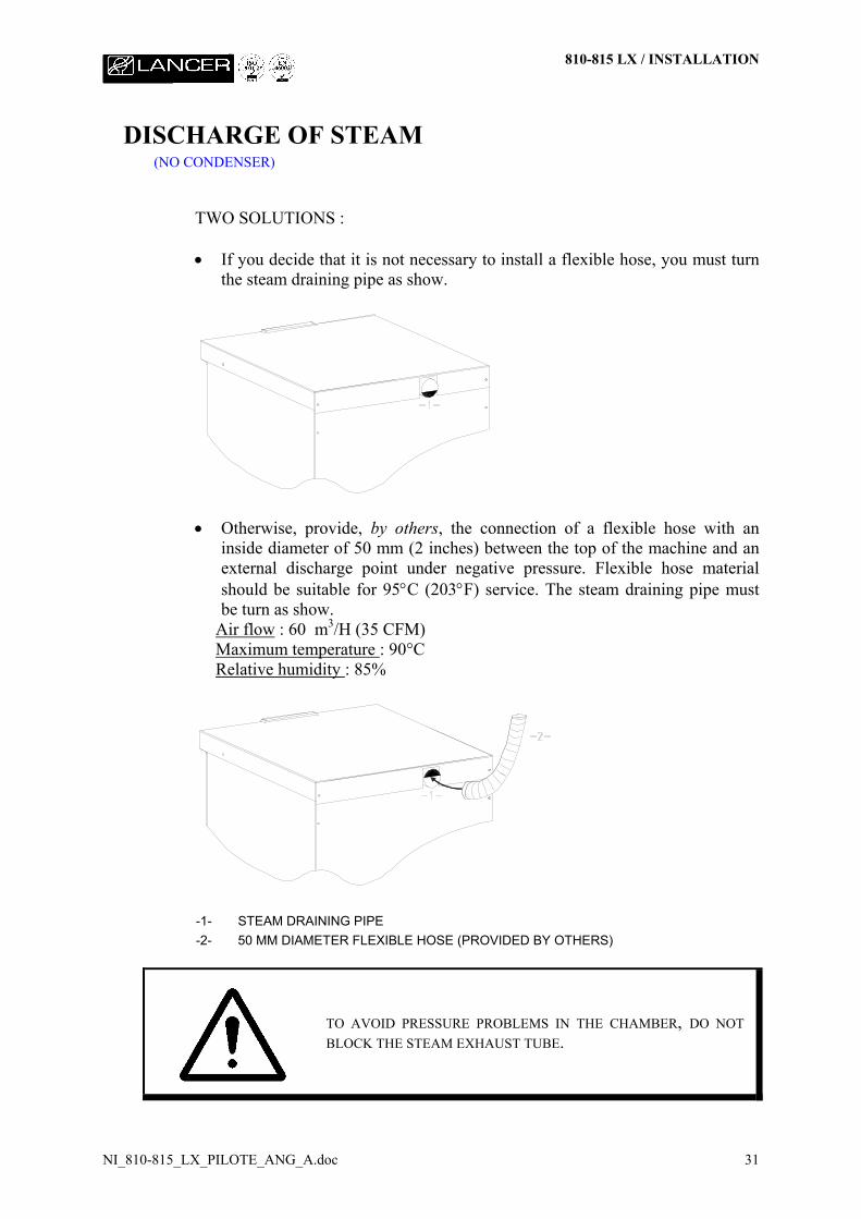
DISCHARGE OF STEAM(NO CONDENSER)
TWO SOLUTIONS :
• If you decide that it is not necessary to install a flexible hose, you must turnthe steam draining pipe as show.
• Otherwise, provide, by others, the connection of a flexible hose with aninside diameter of 50 mm (2 inches) between the top of the machine and anexternal discharge point under negative pressure. Flexible hose materialshould be suitable for 95°C (203°F) service. The steam draining pipe mustbe turn as show.
Air flow : 60 m3/H (35 CFM)Maximum temperature : 90°CRelative humidity : 85%
-1- STEAM DRAINING PIPE-2- 50 MM DIAMETER FLEXIBLE HOSE (PROVIDED BY OTHERS)
TO AVOID PRESSURE PROBLEMS IN THE CHAMBER, DO NOTBLOCK THE STEAM EXHAUST TUBE.
810 LX / INSTALLATION
NI_810-815_LX_PILOTE_ANG_A.doc 32
THE WASHING PRODUCTS(STANDARD)
NON-FOAMING DETERGENTPlace a container of NON-FOAMING LIQUID DETERGENT next to thewasher at a maximum height of 150 mm (6 inches) above floor level. Removethe cap from the detergent container and insert the detergent suction tube into thedetergent container. Tighten the cap.
IT IS STRICTLY PROHIBITED TO USE SOLVENTS AS DETERGENT.
PLEASE REFER TO SUPPLIERS MATERIAL SAFETY DATA SHEET FORSPECIFIC INFORMATION REGARDING THE DETERGENT USED INTHIS EQUIPMENT.
NEUTRALIZING ACIDPlace a container of NEUTRALIZING ACID next to the washer at a maximumheight of 150 mm (6 inches) above floor level. Remove the cap from the acidcontainer and insert the acid suction tube into the acid container. Tighten thecap.
THE USE OF NITRIC ACID IS PROHIBITED. ONLY DILUTEPHOSPHORIC, ACETIC AND CITRIC ACIDS CAN BE USED.
PLEASE REFER TO SUPPLIERS MATERIAL SAFETY DATA SHEET FORSPECIFIC INFORMATION REGARDING THE ACID USED IN THISEQUIPMENT.
BEFORE CARRYING OUT ANY WORK ON THE WASHER,MAKE SURE IT IS SWITCHED OFF AT THE DISCONNECTINGSWITCH.
810 LX / INSTALLATION
NI_810-815_LX_PILOTE_ANG_A.doc 33
THE WASHING PRODUCTS(WITH PLINTH / 02010020)
NON-FOAMING DETERGENTPlace a container of NON-FOAMING LIQUID DETERGENT inside the plinthcabinet below the wash chamber. Remove the cap from the detergent containerand insert the detergent suction tube into the detergent container. Tighten thecap.
IT IS STRICTLY PROHIBITED TO USE SOLVENTS AS DETERGENT.
PLEASE REFER TO SUPPLIERS MATERIAL SAFETY DATA SHEET FORSPECIFIC INFORMATION REGARDING THE DETERGENT USED INTHIS EQUIPMENT.
NEUTRALIZING ACIDPlace a container of NEUTRALIZING ACID inside the plinth cabinet below thewash chamber. Remove the cap from the acid container and insert the acidsuction tube into the acid container. Tighten the cap.
THE USE OF NITRIC ACID IS PROHIBITED. ONLY DILUTEPHOSPHORIC, ACETIC AND CITRIC ACIDS CAN BE USED.
PLEASE REFER TO SUPPLIERS MATERIAL SAFETY DATA SHEET FORSPECIFIC INFORMATION REGARDING THE ACID USED IN THISEQUIPMENT.
BEFORE CARRYING OUT ANY WORK ON THE WASHER,MAKE SURE IT IS SWITCHED OFF AT THE DISCONNECTINGSWITCH.