Embed Size (px)
Citation preview
February 2016UIN 211203 A03
INSTALLATIONAND SERVICINGLOGIC HIU (Heat Interface Unit)Indirect 75Indirect 50Direct MTDirect HT
When replacing any part on this appliance, use only spare parts that you can beassured conform to the safety and performance specification that we require.Do not use reconditioned or copy parts that have not been clearly authorised by Ideal.
For the very latest copy of literature for specification and maintenance practices visit our website www.idealcommercialboilers.com where you can download the relevant information in PDF format.
GENERAL
2 LOGIC HIU - Installation & Servicing / Users
CONTENTS PageIntroduction ...................................................................... 2Safety Instructions .......................................................... 3Logic HIU 75 Indirect & Logic HIU 50 Indirect ...... 4 to 13Specification Indirect ....................................................... 4Technical Specification .................................................... 5Layout & Dimensions ....................................................... 6Schematic & Flow Information ................................ 7 to 8Hardware Content & Options .......................................... 9Electronic Control System ............................................ 10Electrical Connections ................................................... 11Electrical Control Operation .......................................... 12Displayed Error Codes ......................................... 12 to 13Logic HIU Direct MT & Logic HIU Direct HT ........ 14 to 23Specification Direct ........................................................ 14Technical Specification .................................................. 15Layout & Dimensions ..................................................... 16Schematic & Flow Information ............................ 17 to 18Hardware Content & Options ........................................ 19Electronic Control System............................................. 20Electronic Control Connections .................................... 21Electrical Control Operation .......................................... 22Displayed Error Codes ......................................... 22 to 23Installation ....................................................................... 24Commissioning ............................................................... 25Heat Meter ....................................................................... 25Maintenance .......................................................... 26 to 27Fault diagnostics .................................................. 28 to 29
LOGIC HIUUnit UIN No.Logic HIU Indirect 75 211093Logic HIU Indirect 50 211094Logic HIU Direct MT 211095Logic HIU Direct HT 211096Logic HIU Indirect 75 (+ CF ECHO II Mbus 1 Meter) 211346Logic HIU Indirect 50 (+ CF ECHO II Mbus 1 Meter) 211347Logic HIU Direct MT (+ CF ECHO II Mbus 1 Meter) 211348Logic HIU Direct HT (+ CF ECHO II Mbus 1 Meter) 211349Logic HIU Indirect 75 (+ CF ULTRAMAX X V PS Meter) 211350Logic HIU Indirect 50 (+ CF ULTRAMAX X V PS Meter) 211351Logic HIU Direct MT (+ CF ULTRAMAX X V PS Meter) 211352Logic HIU Direct HT (+ CF ULTRAMAX X V PS Meter) 211353
Health & Safety Document No. 635. (The electrical at work regulations 1989). The manufacturer’s notes must NOT be taken, in any way, as overriding statutory obligations.
IMPORTANT. These appliances are CE certified for safety and performance. It is, therefore, important that no external control devices, e.g. economisers etc., are directly connected to these appliances unless covered by these Installation and Servicing Instructions or as otherwise recommended by Ideal Boilers in writing, If in doubt please enquire.
Any direct connection of a control device not approved by Ideal Boilers could invalidate the certification and the normal appliance warranty.
INTRODUCTIONThe Ideal Heat Interface Units (HIUs) are designed for use in conjunction with an external central plant heat source. Examples of central plant systems include centralised boilers, district heating or central energy systems using renewable energy sources.
Detailed recommendations are contained in the following British Standard Codes of Practice:
BSEN.12828:2003 Heating Systems in buildings: Design for water based systems.
BSEN.12831:2003 Heating Systems in buildings: Method for calculation of the design heat load.
BSEN.13831 Specification for: Expansion vessels using an internal diaphragm, for sealed hot water heating systems.
BSEN.14336:2004 Heating Systems in buildings: Installation and commissioning of water based heating systems.
The appliance is suitable only for installation in GB and IE and should be installed in accordance with the rules in force.
The appropriate Building Regulations either The Building Regulations, The Building Regulations (Scotland), Building Regulations (Northern Ireland).
The Water Fittings Regulations or Water byelaws in Scotland.
The Current I.E.E. Wiring Regulations. In IE, the installation must be carried out by a Competent Person and installed in accordance with the current edition of I.S.813 and the current Building Regulations and reference should be made to the current ETCI rules for electrical installation. Where no specific instructions are given, reference should be made to the relevant British Standard Code of Practice.
GENERAL
3LOGIC HIU - Installation & Servicing / Users
SAFETYThese instructions need to be read and understood before installing or maintaining these units. FAILURE TO FOLLOW THESE INSTRUCTION COULD RESULT IN A SAFETY HAZARD.
The device must be installed, commissioned and maintained by qualified technical personnel in accordance with national regulations and /or relevant local requirements.
SAFE HANDLINGThis HIU unit may require two or more operatives to move it to its installation site, remove it from its packaging base and during movement into its installation location. Maneuvering the appliance may include the use of a sack truck and involve lifting, pushing and pulling.
Caution should be exercised during these operations.
Operatives should be knowledgeable in handling techniques when performing these tasks and the following precautions should be considered:
• Grip the appliance at the base.• Be physically capable.• Use personal protective equipment as appropriate, e.g. gloves, safety footwear.
During all maneuvers and handling actions, every attempt should be made to ensure the following unless unavoidable and/or the weight is light.
• Keep back straight.• Avoid twisting at the waist.• Avoid upper body/top heavy bending.• Always grip with the palm of the hand.• Use designated hand holds.• Keep load as close to the body as possible.• Always use assistance if required.
SAFE HANDLING OF SUBSTANCESNo asbestos, mercury or CFCs are included in any part of the boiler or its manufacture.
INSTALLATION SAFE INSTRUCTIONS
• The device must be installed, commissioned and maintained by qualified technical personnel in accordance with national regulations and/or relevant local requirements.
• If the device is not installed, commissioned and maintained correctly in accordance with the instructions provided in this manual, it may not work correctly and may endanger the user.
• This device cannot be used in areas at risk of explosion or fire.
• Ensure all electrical devices are protected from water when maintaining the water based components.
• The device must not be exposed to water drops or humidity, direct sunlight, the elements, heat sources or high intensity electromagnetic fields.
• Flush the pipe work thoroughly (using the optional flushing bypass UIN 211097) before installing the HIU to remove any particles, rust, incrustations, lime scale, welding slag and any other contaminants. The water circuits must be clean and free from debris.
• Make sure that all connection fittings are watertight.
• When connecting water pipes, make sure that threaded connections are not mechanically overstressed. Over time this may result in breakage, causing water damage and/or personal injury.
• Water temperatures higher than 50˚C may cause severe burns. When installing, commissioning and maintaining the device, take the necessary precautions so that these temperatures will not be hazardous for people.
• In the case of particularly hard or impure water, there must be suitable provision for filtering and treating the water before it enters the device, in accordance with current legislation. Failure to do so may result in the HIU becoming damaged or working incorrectly.
• Any use of the HIU other than its intended use is prohibited.
• Any coupling of the device with other system components must be made while taking the operational characteristics of both units into consideration.
• An incorrect coupling could compromise the operation of the device and/or system.
• Electrical installation must only be carried out by a qualified technician, in accordance with current requirements.
• When connecting a room thermostat to this Unit NOTE IT IS A VOLT FREE CONNECTION. DO NOT CONNECT AN EXTERNAL VOLTAGE SUPPLY TO THE ROOM THERMOSTAT TERMINALS.
MAINTENANCE SAFETY• Before removing casing; the HIU unit should be in an off state
and cool enough to work on without the risk of burns from high temperature components.
• The unit should be electrically isolated with the use of an external bipolar switch. (No automated power switch systems should be used as a direct isolation method for this HIU unit).
• During installation and maintenance operations, always avoid direct contact with live or potentially hazardous parts.
• Take care to follow the instruction on any correctly rate pressure equipment when working on the high pressure systems on these units.
• Suitable automatic protection devices in compliance with current legislation can be used in conjunction with a bipolar isolation switch system.
• The device must always be earthed before it is connected to the electric supply. If the device has to be removed, always disconnect the earth connection after disconnecting the electric supply. Check that the earth connection has been made to the highest of standards under current legislation.
INDIRECT SPECIFICATION
4 LOGIC HIU - Installation & Servicing / Users
1 APPLIANCE TYPE
INDIRECT
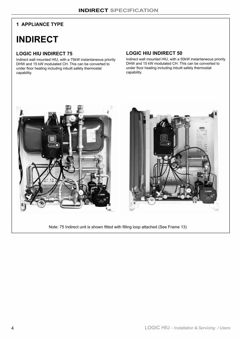
LOGIC HIU INDIRECT 75Indirect wall mounted HIU, with a 75kW instantaneous priority DHW and 15 kW modulated CH. This can be converted to under floor heating including inbuilt safety thermostat capability.
LOGIC HIU INDIRECT 50Indirect wall mounted HIU, with a 50kW instantaneous priority DHW and 15 kW modulated CH. This can be converted to under floor heating including inbuilt safety thermostat capability.
Note: 75 Indirect unit is shown fitted with filling loop attached (See Frame 13)
INDIRECT SPECIFICATION
5LOGIC HIU - Installation & Servicing / Users
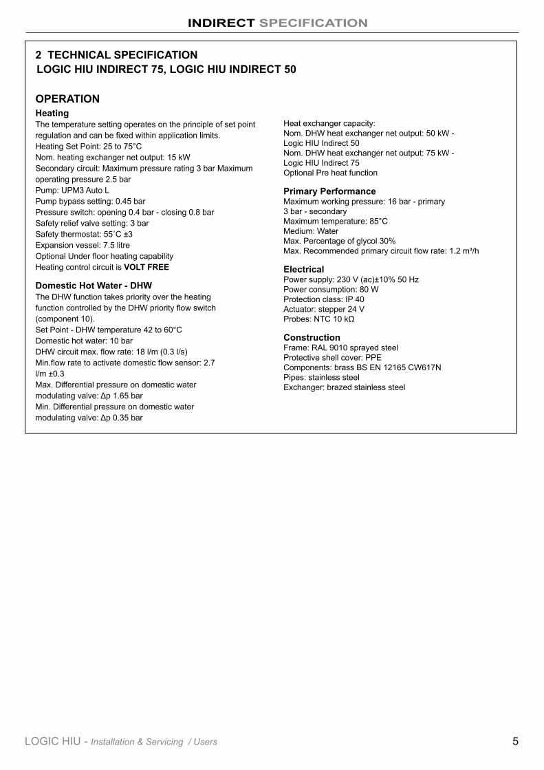
2 TECHNICAL SPECIFICATION
OPERATIONHeatingThe temperature setting operates on the principle of set point regulation and can be fixed within application limits. Heating Set Point: 25 to 75°C Nom. heating exchanger net output: 15 kW Secondary circuit: Maximum pressure rating 3 bar Maximum operating pressure 2.5 bar Pump: UPM3 Auto L Pump bypass setting: 0.45 bar Pressure switch: opening 0.4 bar - closing 0.8 bar Safety relief valve setting: 3 bar Safety thermostat: 55˚C ±3 Expansion vessel: 7.5 litre Optional Under floor heating capability Heating control circuit is VOLT FREE
Domestic Hot Water - DHWThe DHW function takes priority over the heating function controlled by the DHW priority flow switch (component 10). Set Point - DHW temperature 42 to 60°C Domestic hot water: 10 bar DHW circuit max. flow rate: 18 l/m (0.3 l/s) Min.flow rate to activate domestic flow sensor: 2.7 l/m ±0.3 Max. Differential pressure on domestic water modulating valve: Δp 1.65 barMin. Differential pressure on domestic water modulating valve: Δp 0.35 bar
Heat exchanger capacity: Nom. DHW heat exchanger net output: 50 kW - Logic HIU Indirect 50 Nom. DHW heat exchanger net output: 75 kW - Logic HIU Indirect 75 Optional Pre heat function
Primary PerformanceMaximum working pressure: 16 bar - primary 3 bar - secondary Maximum temperature: 85°C Medium: Water Max. Percentage of glycol 30% Max. Recommended primary circuit flow rate: 1.2 m³/h
ElectricalPower supply: 230 V (ac)±10% 50 Hz Power consumption: 80 W Protection class: IP 40 Actuator: stepper 24 V Probes: NTC 10 kΩ
ConstructionFrame: RAL 9010 sprayed steel Protective shell cover: PPE Components: brass BS EN 12165 CW617N Pipes: stainless steel Exchanger: brazed stainless steel
LOGIC HIU INDIRECT 75, LOGIC HIU INDIRECT 50
INDIRECT SPECIFICATION
6 LOGIC HIU - Installation & Servicing / Users
ON DHW CH FAULTRESET
2118
10
RESETON DHW CH FAULT
1
2
2
1
0
3
4
bar
20
17
16
3
21
1911
5
13
715
4
14
822C D 2E F
1
19
11
5
13
7
15
4
14
22
A B
2C D E F
9 8 2
21
20
18
10
17
16
3
2
A B
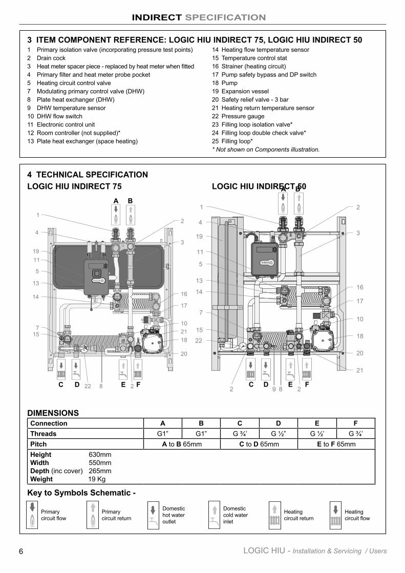
DIMENSIONS
2
Primary circuit flow
Key to Symbols Schematic -
Connection A B C D E FThreads G1” G1” G ¾’ G ½” G ½’ G ¾’Pitch A to B 65mm C to D 65mm E to F 65mmHeight 630mm Width 550mm Depth (inc cover) 265mm Weight 19 Kg
3 ITEM COMPONENT REFERENCE: LOGIC HIU INDIRECT 75, LOGIC HIU INDIRECT 501 Primary isolation valve (incorporating pressure test points) 2 Drain cock3 Heat meter spacer piece - replaced by heat meter when fitted4 Primary filter and heat meter probe pocket5 Heating circuit control valve7 Modulating primary control valve (DHW)8 Plate heat exchanger (DHW)9 DHW temperature sensor10 DHW flow switch11 Electronic control unit12 Room controller (not supplied)*13 Plate heat exchanger (space heating)
14 Heating flow temperature sensor15 Temperature control stat16 Strainer (heating circuit)17 Pump safety bypass and DP switch18 Pump19 Expansion vessel20 Safety relief valve - 3 bar21 Heating return temperature sensor22 Pressure gauge23 Filling loop isolation valve*24 Filling loop double check valve*25 Filling loop** Not shown on Components illustration.
4 TECHNICAL SPECIFICATIONLOGIC HIU INDIRECT 75 LOGIC HIU INDIRECT 50
2
Primary circuit return
2
Domestic hot water outlet
2
Domestic cold water inlet
2
Heating circuit return
2
Heating circuit flow
INDIRECT SPECIFICATION
Flowrate - l/s
Flowrate - l/s
COMMON HEATING SYSTEM
COMMON HEATING SYSTEM
7LOGIC HIU - Installation & Servicing / Users
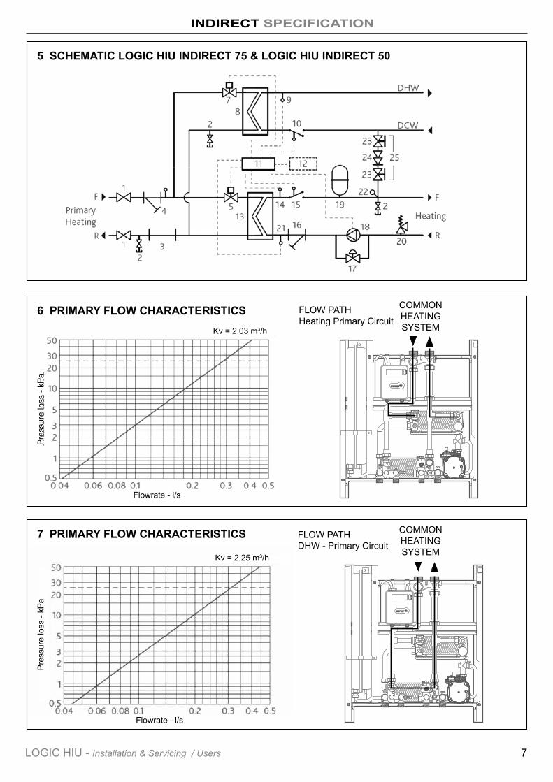
FLOW PATH Heating Primary Circuit
5 SCHEMATIC LOGIC HIU INDIRECT 75 & LOGIC HIU INDIRECT 50
6 PRIMARY FLOW CHARACTERISTICS
7 PRIMARY FLOW CHARACTERISTICS FLOW PATH DHW - Primary Circuit
R ES ETON DHW C H FAULT
1
2
R ES ETON DHW C H FAULT
1
2
Kv = 2.25 m3/h
Kv = 2.03 m3/h
Pres
sure
loss
- kP
aPr
essu
re lo
ss -
kPa
INDIRECT SPECIFICATION
8 LOGIC HIU - Installation & Servicing / Users
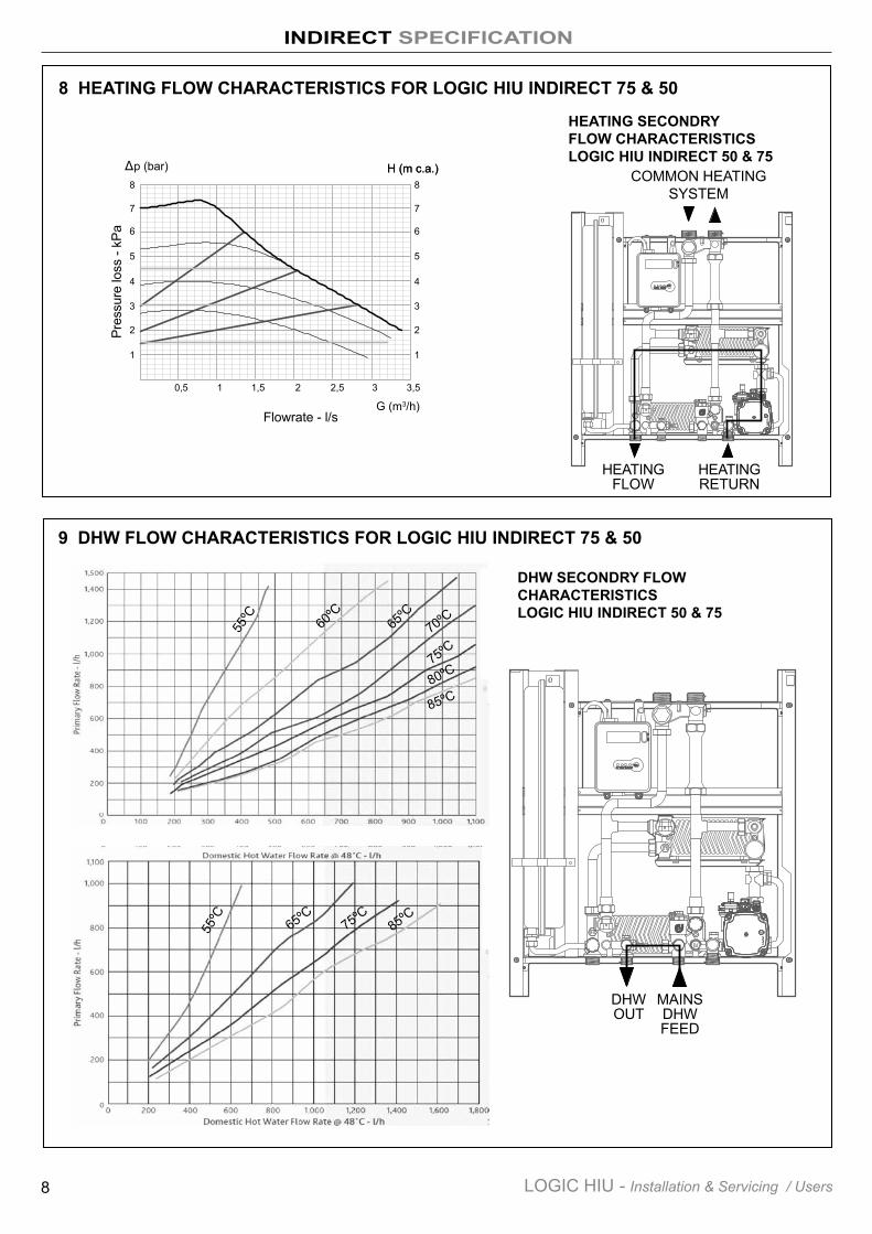
8 HEATING FLOW CHARACTERISTICS FOR LOGIC HIU INDIRECT 75 & 50
9 DHW FLOW CHARACTERISTICS FOR LOGIC HIU INDIRECT 75 & 50
R ES ETON DHW C H FAULT
1
2
0
10
20
30
40
50
60
0 0.2 0.1 0.3 0.4 0.5 0.6
3
2
1
R ES ETON DHW C H FAULT
1
2
55ºC
65ºC
55ºC
85ºC75ºC
85ºC80ºC75ºC70ºC65
ºC60
ºC
HEATING SECONDRY FLOW CHARACTERISTICS LOGIC HIU INDIRECT 50 & 75
DHW SECONDRY FLOW CHARACTERISTICS LOGIC HIU INDIRECT 50 & 75
HEATING FLOW
HEATING RETURN
DHW OUT
MAINS DHW FEED
COMMON HEATING SYSTEM
Δ H (m c.a.)H (m c.a.)p (bar)
3 3,5
G (m3/h)
0,6
0,4
0,3
0,2
0,1
02,521,50,5
0,5
1
6
4
3
2
1
5
70,7
0,8 8
Flowrate - l/s
Pres
sure
loss
- kP
a
INDIRECT HARDWARE CONTENTS
9LOGIC HIU - Installation & Servicing / Users
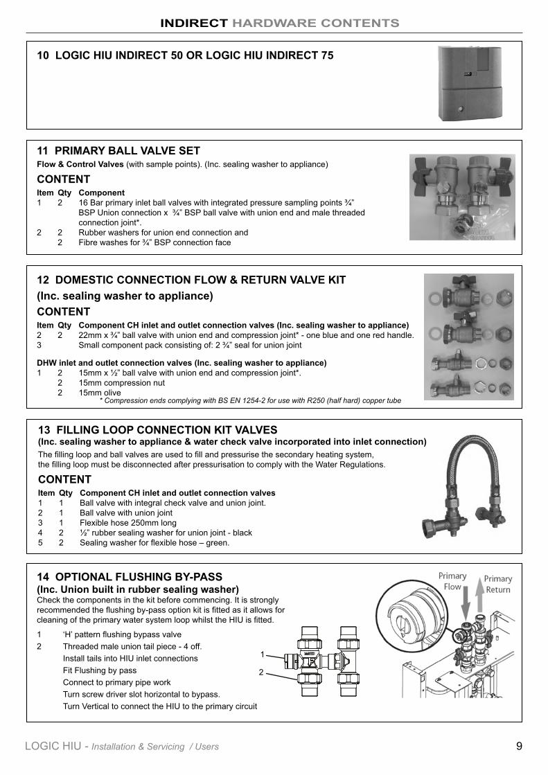
11 PRIMARY BALL VALVE SETFlow & Control Valves (with sample points). (Inc. sealing washer to appliance)
CONTENTItem Qty Component1 2 16 Bar primary inlet ball valves with integrated pressure sampling points ¾” BSP Union connection x ¾” BSP ball valve with union end and male threaded connection joint*. 2 2 Rubber washers for union end connection and 2 Fibre washes for ¾” BSP connection face
12 DOMESTIC CONNECTION FLOW & RETURN VALVE KIT(Inc. sealing washer to appliance)CONTENTItem Qty Component CH inlet and outlet connection valves (Inc. sealing washer to appliance)2 2 22mm x ¾” ball valve with union end and compression joint* - one blue and one red handle. 3 Small component pack consisting of: 2 ¾” seal for union joint
DHW inlet and outlet connection valves (Inc. sealing washer to appliance)1 2 15mm x ½” ball valve with union end and compression joint*. 2 15mm compression nut 2 15mm olive
13 FILLING LOOP CONNECTION KIT VALVES (Inc. sealing washer to appliance & water check valve incorporated into inlet connection)The filling loop and ball valves are used to fill and pressurise the secondary heating system, the filling loop must be disconnected after pressurisation to comply with the Water Regulations.
CONTENTItem Qty Component CH inlet and outlet connection valves1 1 Ball valve with integral check valve and union joint. 2 1 Ball valve with union joint 3 1 Flexible hose 250mm long 4 2 ½” rubber sealing washer for union joint - black 5 2 Sealing washer for flexible hose – green.
14 OPTIONAL FLUSHING BY-PASS (Inc. Union built in rubber sealing washer) Check the components in the kit before commencing. It is strongly recommended the flushing by-pass option kit is fitted as it allows for cleaning of the primary water system loop whilst the HIU is fitted.
1 ‘H’ pattern flushing bypass valve 2 Threaded male union tail piece - 4 off. Install tails into HIU inlet connections Fit Flushing by pass Connect to primary pipe work Turn screw driver slot horizontal to bypass. Turn Vertical to connect the HIU to the primary circuit
10 LOGIC HIU INDIRECT 50 OR LOGIC HIU INDIRECT 75
* Compression ends complying with BS EN 1254-2 for use with R250 (half hard) copper tube
2
1
10 LOGIC HIU - Installation & Servicing / Users
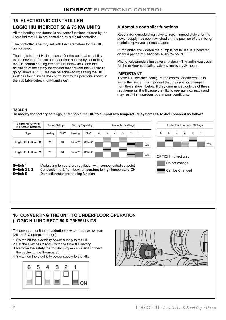
15 ELECTRONIC CONTROLLERLOGIC HIU INDIRECT 50 & 75 KW UNITSAll the heating and domestic hot water functions offered by the Logic Indirect HIUs are controlled by a digital controller.
The controller is factory set with the parameters for the HIU unit ordered.
The Logic Indirect HIU versions offer the optional capability to be converted for use on under floor heating by controlling the CH central heating temperature below 45 C and the activation of the safety thermostat that prevent the CH circuit going above 45 °C. This can be achieved by setting the DIP switches found inside the control box to the positions shown in the sub table below (right-hand side).
Automatic controller functions
Reset mixing/modulating valve to zero - Immediately after the power supply has been switched on, the position of the mixing/modulating valves is reset to zero.
Pump anti-sieze - When the pump is not in use, it is powered on for a period of 5 seconds every 24 hours.
Mixing valve/modulating valve anti-sieze - The anti-sieze cycle for the mixing/modulating valve is run every 24 hours.
IMPORTANTThese DIP switches configure the control for different units within the range. It is important that they are not changed from those shown below. If they carehanged outside of these requirements, it will cause the HIU to operate incorrectly and may result in hazardous operational conditions.
Electronic Control Dip Switch Settings Factory Settings Setting Capability Production settings
Type Heating DHW Heating DHW 6 5 4 3 2 1
Logic HIU Indirect 50 75 54 25 to 75 42 to 60ON
Logic HIU Indirect 75 75 54 25 to 75 42 to 60ON
Underfloor Low Temp Settings
6 5 4 3 2 1
ON
Do not change
Can be Changed
OPTION Indirect only
Switch 1 Modulating temperature regulation with compensated set point Switch 2 & 3 Conversion to & from Low temperature to high temperature CH Switch 5 Domestic water pre heating function
TABLE 1To modify the factory settings, and enable the HIU to support low temperature systems 25 to 45ºC proceed as follows
16 CONVERTING THE UNIT TO UNDERFLOOR OPERATION (LOGIC HIU INDIRECT 50 & 75KW UNITS)
To convert the unit to an underfloor low temperature system (25 to 45°C operation range)1 Switch off the electricity power supply to the HIU2 Set the switches 2 and 3 with the ON-OFF setting3 Remove the safety thermostat jumper cable and connect
the cables to the thermostat.4 Switch on the electricity power supply to the HIU.
INDIRECT ELECTRONIC CONTROL
11LOGIC HIU - Installation & Servicing / Users
FUSE 5x20
1 2 3 45a
67 8
5
9
10
13
11
12
Room thermostat
Electric supply:
6 5 4 3 2 1
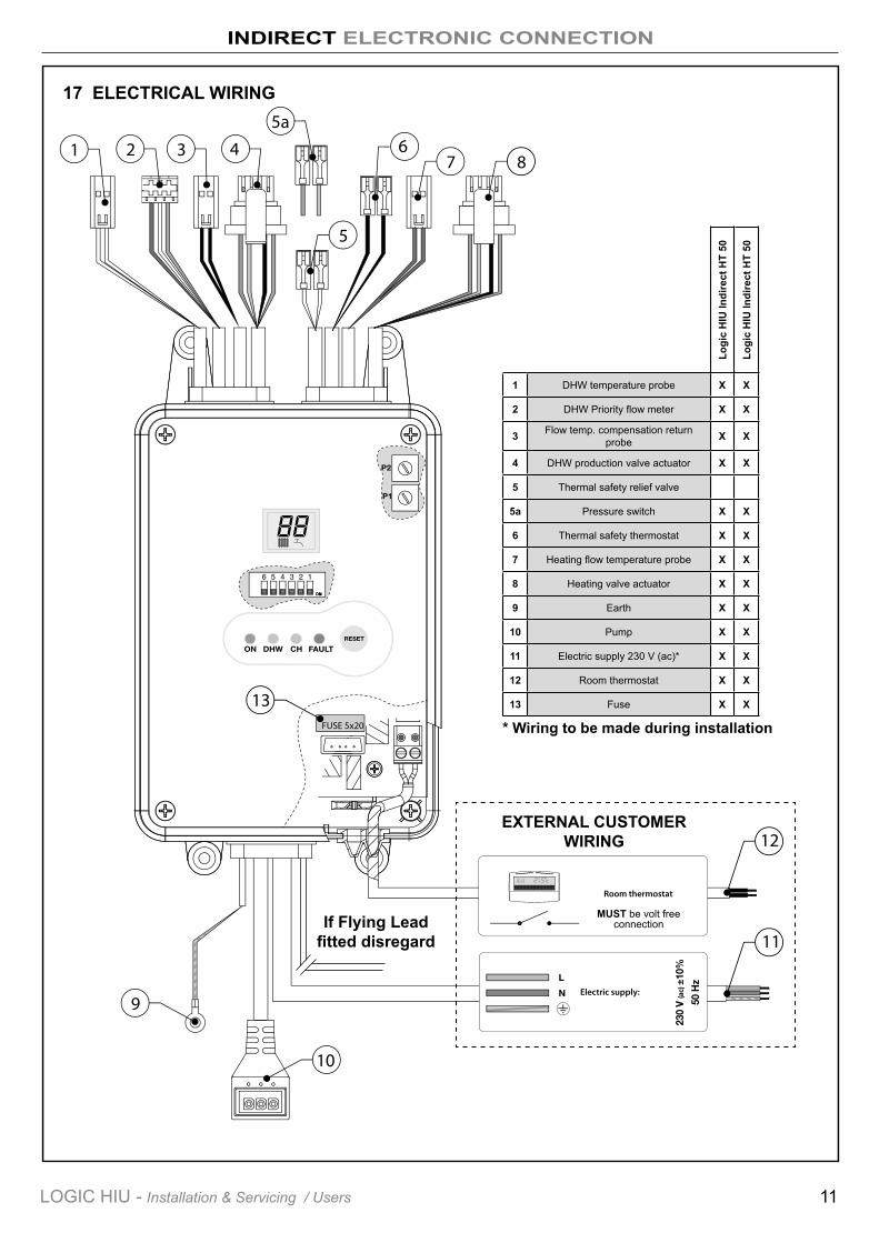
17 ELECTRICAL WIRING
1 DHW temperature probe X X
2 DHW Priority flow meter X X
3 Flow temp. compensation return probe X X
4 DHW production valve actuator X X
5 Thermal safety relief valve
5a Pressure switch X X
6 Thermal safety thermostat X X
7 Heating flow temperature probe X X
8 Heating valve actuator X X
9 Earth X X
10 Pump X X
11 Electric supply 230 V (ac)* X X
12 Room thermostat X X
13 Fuse X X
* Wiring to be made during installationLo
gic
HIU
Indi
rect
HT
50
Logi
c H
IU In
dire
ct H
T 50
INDIRECT ELECTRONIC CONNECTION
EXTERNAL CUSTOMER WIRING
MUST be volt free connectionIf Flying Lead
fitted disregard
12 LOGIC HIU - Installation & Servicing / Users
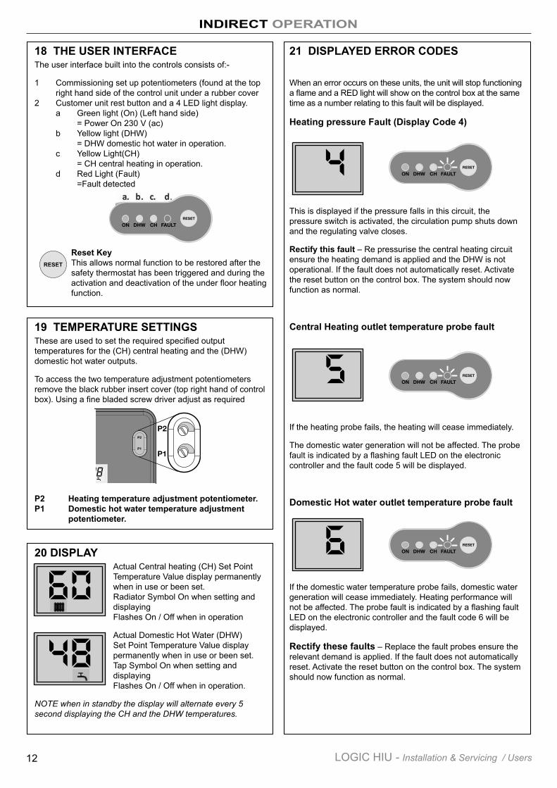
18 THE USER INTERFACEThe user interface built into the controls consists of:-
1 Commissioning set up potentiometers (found at the top right hand side of the control unit under a rubber cover 2 Customer unit rest button and a 4 LED light display. a Green light (On) (Left hand side) = Power On 230 V (ac) b Yellow light (DHW) = DHW domestic hot water in operation. c Yellow Light(CH) = CH central heating in operation. d Red Light (Fault) =Fault detected
Reset KeyThis allows normal function to be restored after the safety thermostat has been triggered and during the activation and deactivation of the under floor heating function.
19 TEMPERATURE SETTINGSThese are used to set the required specified output temperatures for the (CH) central heating and the (DHW) domestic hot water outputs.
To access the two temperature adjustment potentiometers remove the black rubber insert cover (top right hand of control box). Using a fine bladed screw driver adjust as required
P2 Heating temperature adjustment potentiometer.P1 Domestic hot water temperature adjustment potentiometer.
20 DISPLAYActual Central heating (CH) Set Point Temperature Value display permanently when in use or been set. Radiator Symbol On when setting and displaying Flashes On / Off when in operation
Actual Domestic Hot Water (DHW) Set Point Temperature Value display permanently when in use or been set. Tap Symbol On when setting and displaying Flashes On / Off when in operation.
NOTE when in standby the display will alternate every 5 second displaying the CH and the DHW temperatures.
21 DISPLAYED ERROR CODES
When an error occurs on these units, the unit will stop functioning a flame and a RED light will show on the control box at the same time as a number relating to this fault will be displayed.
Heating pressure Fault (Display Code 4)
This is displayed if the pressure falls in this circuit, the pressure switch is activated, the circulation pump shuts down and the regulating valve closes.
Rectify this fault – Re pressurise the central heating circuit ensure the heating demand is applied and the DHW is not operational. If the fault does not automatically reset. Activate the reset button on the control box. The system should now function as normal.
Central Heating outlet temperature probe fault
If the heating probe fails, the heating will cease immediately.
The domestic water generation will not be affected. The probe fault is indicated by a flashing fault LED on the electronic controller and the fault code 5 will be displayed.
Domestic Hot water outlet temperature probe fault
If the domestic water temperature probe fails, domestic water generation will cease immediately. Heating performance will not be affected. The probe fault is indicated by a flashing fault LED on the electronic controller and the fault code 6 will be displayed.
Rectify these faults – Replace the fault probes ensure the relevant demand is applied. If the fault does not automatically reset. Activate the reset button on the control box. The system should now function as normal.
INDIRECT OPERATION
RESET
13LOGIC HIU - Installation & Servicing / Users
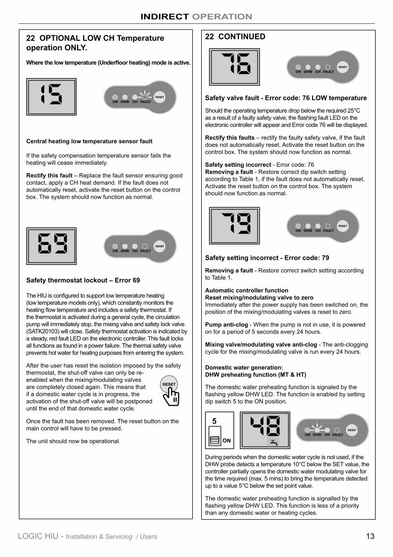
22 OPTIONAL LOW CH Temperature operation ONLY.
Where the low temperature (Underfloor heating) mode is active.
Central heating low temperature sensor fault
If the safety compensation temperature sensor fails the heating will cease immediately.
Rectify this fault – Replace the fault sensor ensuring good contact, apply a CH heat demand. If the fault does not automatically reset, activate the reset button on the control box. The system should now function as normal.
Safety thermostat lockout – Error 69
The HIU is configured to support low temperature heating (low temperature models only), which constantly monitors the heating flow temperature and includes a safety thermostat. If the thermostat is activated during a general cycle, the circulation pump will immediately stop, the mixing valve and safety lock valve (SATK20103) will close. Safety thermostat activation is indicated by a steady, red fault LED on the electronic controller. This fault locks all functions as found in a power failure. The thermal safety valve prevents hot water for heating purposes from entering the system.
After the user has reset the isolation imposed by the safety thermostat, the shut-off valve can only be re-enabled when the mixing/modulating valves are completely closed again. This means that if a domestic water cycle is in progress, the activation of the shut-off valve will be postponed until the end of that domestic water cycle.
Once the fault has been removed. The reset button on the main control will have to be pressed.
The unit should now be operational.
INDIRECT OPERATION
22 CONTINUED
Safety valve fault - Error code: 76 LOW temperature
Should the operating temperature drop below the required 25°C as a result of a faulty safety valve; the flashing fault LED on the electronic controller will appear and Error code 76 will be displayed.
Rectify this faults – rectify the faulty safety valve, if the fault does not automatically reset. Activate the reset button on the control box. The system should now function as normal.
Safety setting incorrect - Error code: 76 Removing a fault - Restore correct dip switch setting according to Table 1, if the fault does not automatically reset. Activate the reset button on the control box. The system should now function as normal.
Safety setting incorrect - Error code: 79
Removing a fault - Restore correct switch setting according to Table 1.
Automatic controller function Reset mixing/modulating valve to zero Immediately after the power supply has been switched on, the position of the mixing/modulating valves is reset to zero.
Pump anti-clog - When the pump is not in use, it is powered on for a period of 5 seconds every 24 hours.
Mixing valve/modulating valve anti-clog - The anti-clogging cycle for the mixing/modulating valve is run every 24 hours.
Domestic water generation: DHW preheating function (MT & HT)
The domestic water preheating function is signaled by the flashing yellow DHW LED. The function is enabled by setting dip switch 5 to the ON position.
During periods when the domestic water cycle is not used, if the DHW probe detects a temperature 10°C below the SET value, the controller partially opens the domestic water modulating valve for the time required (max. 5 mins) to bring the temperature detected up to a value 5°C below the set point value.
The domestic water preheating function is signalled by the flashing yellow DHW LED. This function is less of a priority than any domestic water or heating cycles.
5
ON
DIRECT SPECIFICATION
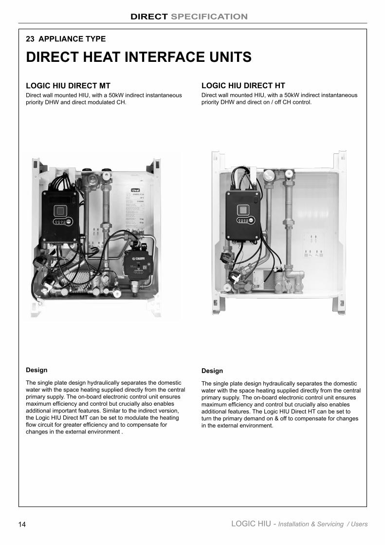
23 APPLIANCE TYPE
LOGIC HIU DIRECT MT Direct wall mounted HIU, with a 50kW indirect instantaneous priority DHW and direct modulated CH.
Design
The single plate design hydraulically separates the domestic water with the space heating supplied directly from the central primary supply. The on-board electronic control unit ensures maximum efficiency and control but crucially also enables additional important features. Similar to the indirect version, the Logic HIU Direct MT can be set to modulate the heating flow circuit for greater efficiency and to compensate for changes in the external environment .
LOGIC HIU DIRECT HTDirect wall mounted HIU, with a 50kW indirect instantaneous priority DHW and direct on / off CH control.
Design
The single plate design hydraulically separates the domestic water with the space heating supplied directly from the central primary supply. The on-board electronic control unit ensures maximum efficiency and control but crucially also enables additional features. The Logic HIU Direct HT can be set to turn the primary demand on & off to compensate for changes in the external environment.
DIRECT HEAT INTERFACE UNITS
14 LOGIC HIU - Installation & Servicing / Users
DIRECT SPECIFICATION
24 TECHNICAL SPECIFICATION
OPERATIONHeatingThe temperature setting operates on the principle of set point regulation and can be fixed within application limits.
Heating Set Point (Logic HIU Direct MT): 45 to 65°C
Heating Set Point (Logic HIU Direct HT): Function not available
Heating circuit: Maximum pressure rating: As Primary and Heating circuit controls permit.
Pump: UPM3 Auto L
Pump bypass setting: 0.45 bar
Heating control circuit is VOLT FREE
Domestic Hot Water - DHWThe DHW function takes priority over the heating function controlled by the DHW priority flow switch
Set Point - DHW temperature 42 to 60°C
Domestic hot water: 10 bar
DHW circuit max. Flow rate: 18 l/m (0.3 l/s)
Min.flow rate to activate domestic flow sensor: 2.7 l/m ±0.3
Max. Differential pressure on domestic water modulating valve: Δp 0.9 barMin. Differential pressure on domestic water modulating valve: Δp 0.35 bar
Heat exchanger capacity: Nom. DHW heat exchanger net output: 50 kW - Logic HIU Indirect 50.
Optional Pre-heat function.
Primary PerformanceMax. Working pressure: Primary circuit: 10 bar
Maximum temperature: 85°C
Medium: Water
Max. Percentage of glycol 30%
Max. Recommended primary circuit flow rate: 1.2 m³/h
ElectricalPower supply: 230 V (ac)±10% 50 Hz
Power consumption: 80 W Protection class: IP 40
Actuator: stepper 24 V
Probes: NTC 10 kΩ
ConstructionFrame: RAL 9010 sprayed steel
Protective shell cover: PPE
Components: brass BS EN 12165 CW617N
Pipes: stainless steel
Exchanger: brazed stainless steel
LOGIC HIU DIRECT MT & LOGIC HIU DIRECT HT
15LOGIC HIU - Installation & Servicing / Users
DIRECT SPECIFICATION
17
10
3
2
4
1
1
11
19
7
14
98
13
18
2
A
C D E F C D E F
B A B
2
1
11
5
7
14
3
10
68
DIMENSIONS
2
Primary circuit flow
Key to Symbols Schematic -
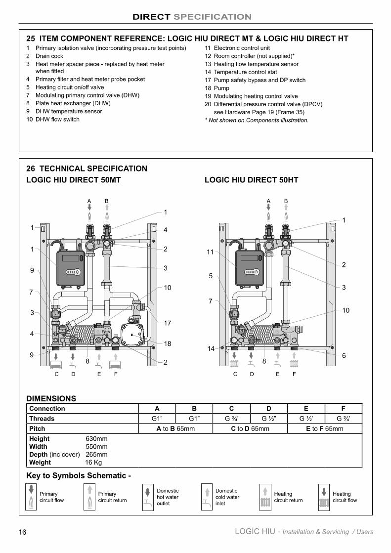
Connection A B C D E FThreads G1” G1” G ¾’ G ½” G ½’ G ¾’Pitch A to B 65mm C to D 65mm E to F 65mmHeight 630mm Width 550mm Depth (inc cover) 265mm Weight 16 Kg
25 ITEM COMPONENT REFERENCE: LOGIC HIU DIRECT MT & LOGIC HIU DIRECT HT1 Primary isolation valve (incorporating pressure test points) 2 Drain cock3 Heat meter spacer piece - replaced by heat meter when fitted4 Primary filter and heat meter probe pocket5 Heating circuit on/off valve7 Modulating primary control valve (DHW)8 Plate heat exchanger (DHW)9 DHW temperature sensor10 DHW flow switch
11 Electronic control unit12 Room controller (not supplied)*13 Heating flow temperature sensor14 Temperature control stat17 Pump safety bypass and DP switch18 Pump19 Modulating heating control valve20 Differential pressure control valve (DPCV) see Hardware Page 19 (Frame 35)* Not shown on Components illustration.
26 TECHNICAL SPECIFICATIONLOGIC HIU DIRECT 50MT LOGIC HIU DIRECT 50HT
2
Primary circuit return
2
Domestic hot water outlet
2
Domestic cold water inlet
2
Heating circuit return
2
Heating circuit flow
16 LOGIC HIU - Installation & Servicing / Users
DIRECT SPECIFICATION
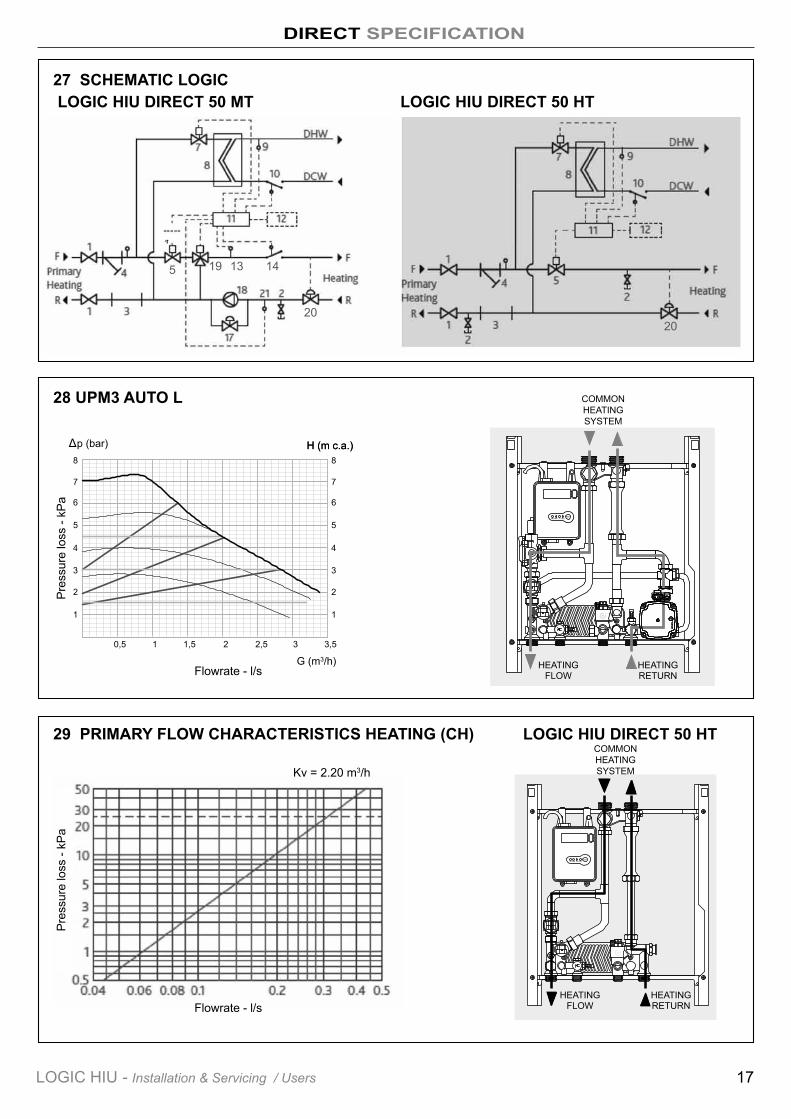
27 SCHEMATIC LOGIC
29 PRIMARY FLOW CHARACTERISTICS HEATING (CH)
LOGIC HIU DIRECT 50 MT LOGIC HIU DIRECT 50 HT
LOGIC HIU DIRECT 50 HT
Kv = 2.20 m3/h
Δ H (m c.a.)H (m c.a.)p (bar)
3 3,5
G (m3/h)
0,6
0,4
0,3
0,2
0,1
02,521,50,5
0,5
1
6
4
3
2
1
5
70,7
0,8 8
2020
5 13 1419
17LOGIC HIU - Installation & Servicing / Users
28 UPM3 AUTO L
HEATING FLOW
HEATING RETURN
HEATING FLOW
HEATING RETURNFlowrate - l/s
COMMON HEATING SYSTEM
Pres
sure
loss
- kP
a
Flowrate - l/s
Pres
sure
loss
- kP
a
COMMON HEATING SYSTEM
DIRECT SPECIFICATION
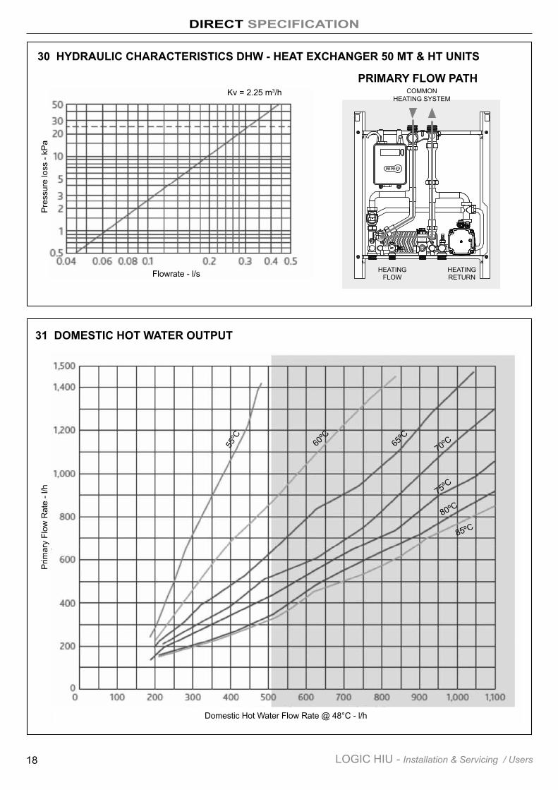
30 HYDRAULIC CHARACTERISTICS DHW - HEAT EXCHANGER 50 MT & HT UNITS
31 DOMESTIC HOT WATER OUTPUT
PRIMARY FLOW PATH
Prim
ary
Flow
Rat
e - l
/h
HEATING FLOW
HEATING RETURN
Domestic Hot Water Flow Rate @ 48°C - l/h
18 LOGIC HIU - Installation & Servicing / Users
Kv = 2.25 m3/h
Flowrate - l/s
Pres
sure
loss
- kP
a
55ºC
85ºC
80ºC
75ºC
70ºC65ºC
60ºC
COMMON HEATING SYSTEM
DIRECT HARDWARE CONTENTS
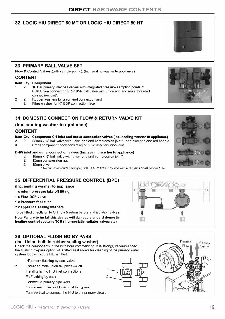
32 LOGIC HIU DIRECT 50 MT OR LOGIC HIU DIRECT 50 HT
35 DIFFERENTIAL PRESSURE CONTROL (DPC)(Inc. sealing washer to appliance)1 x return pressure take off fitting1 x Flow DCP valve1 x Pressure feed tube2 x appliance sealing washersTo be fitted directly on to CH flow & return before and isolation valvesNote Failure to install this device will damage standard domestic heating control systems TCR (thermostatic radiator valves etc)
36 OPTIONAL FLUSHING BY-PASS (Inc. Union built in rubber sealing washer) Check the components in the kit before commencing. It is strongly recommended the flushing by-pass option kit is fitted as it allows for cleaning of the primary water system loop whilst the HIU is fitted.
1 ‘H’ pattern flushing bypass valve 2 Threaded male union tail piece - 4 off. Install tails into HIU inlet connections Fit Flushing by pass Connect to primary pipe work Turn screw driver slot horizontal to bypass. Turn Vertical to connect the HIU to the primary circuit
33 PRIMARY BALL VALVE SETFlow & Control Valves (with sample points). (Inc. sealing washer to appliance)
CONTENTItem Qty Component1 2 16 Bar primary inlet ball valves with integrated pressure sampling points ¾” BSP Union connection x ¾” BSP ball valve with union end and male threaded connection joint*. 2 2 Rubber washers for union end connection and 2 Fibre washes for ¾” BSP connection face
34 DOMESTIC CONNECTION FLOW & RETURN VALVE KIT(Inc. sealing washer to appliance)CONTENTItem Qty Component CH inlet and outlet connection valves (Inc. sealing washer to appliance)2 2 22mm x ¾” ball valve with union end and compression joint* - one blue and one red handle. 3 Small component pack consisting of: 2 ¾” seal for union joint
DHW inlet and outlet connection valves (Inc. sealing washer to appliance)1 2 15mm x ½” ball valve with union end and compression joint*. 2 15mm compression nut 2 15mm olive
* Compression ends complying with BS EN 1254-2 for use with R250 (half hard) copper tube
19LOGIC HIU - Installation & Servicing / Users
2
1
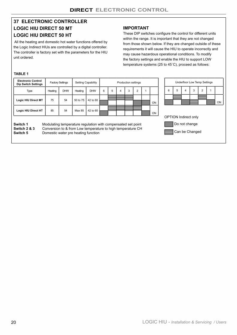
37 ELECTRONIC CONTROLLERLOGIC HIU DIRECT 50 MTLOGIC HIU DIRECT 50 HT All the heating and domestic hot water functions offered by the Logic Indirect HIUs are controlled by a digital controller. The controller is factory set with the parameters for the HIU unit ordered.
IMPORTANTThese DIP switches configure the control for different units within the range. It is important that they are not changed from those shown below. If they are changed outside of these requirements it will cause the HIU to operate incorrectly and may cause hazardous operational conditions. To modify the factory settings and enable the HIU to support LOW temperature systems (25 to 45˚C), proceed as follows:
Electronic Control Dip Switch Settings Factory Settings Setting Capability Production settings
Type Heating DHW Heating DHW 6 5 4 3 2 1
Logic HIU Direct MT 75 54 50 to 75 42 to 60ON
Logic HIU Direct HT 85 54 Max 85 42 to 60ON
Underfloor Low Temp Settings
6 5 4 3 2 1
ON
Do not change
Can be Changed
OPTION Indirect only
Switch 1 Modulating temperature regulation with compensated set point Switch 2 & 3 Conversion to & from Low temperature to high temperature CH Switch 5 Domestic water pre heating function
TABLE 1
DIRECT ELECTRONIC CONTROL
20 LOGIC HIU - Installation & Servicing / Users
FUSE 5x20
1 2 3 45a
67 8
5
9
10
13
11
12
Room thermostat
Electric supply:
6 5 4 3 2 1
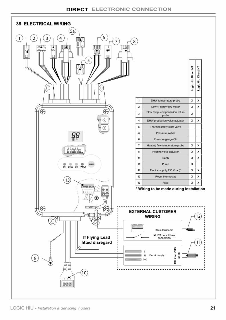
38 ELECTRICAL WIRING
1 DHW temperature probe X X
2 DHW Priority flow meter X X
3 Flow temp. compensation return probe X
4 DHW production valve actuator X X
5 Thermal safety relief valve
5a Pressure switch
6 Pressure gauge CH
7 Heating flow temperature probe X X
8 Heating valve actuator X X
9 Earth X X
10 Pump X
11 Electric supply 230 V (ac)* X X
12 Room thermostat X X
13 Fuse X X
* Wiring to be made during installationLo
gic
HIU
Dire
ct M
T
Logi
c H
IU D
irect
HT
DIRECT ELECTRONIC CONNECTION
21LOGIC HIU - Installation & Servicing / Users
EXTERNAL CUSTOMER WIRING
MUST be volt free connectionIf Flying Lead
fitted disregard
INSTALLATION
22 LOGIC HIU - Installation & Servicing / Users
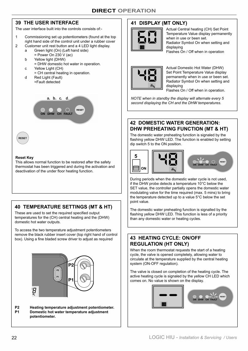
39 THE USER INTERFACEThe user interface built into the controls consists of:-
1 Commissioning set up potentiometers (found at the top right hand side of the control unit under a rubber cover 2 Customer unit rest button and a 4 LED light display. a Green light (On) (Left hand side) = Power On 230 V (ac) b Yellow light (DHW) = DHW domestic hot water in operation. c Yellow Light (CH) = CH central heating in operation. d Red Light (Fault) =Fault detected
Reset KeyThis allows normal function to be restored after the safety thermostat has been triggered and during the activation and deactivation of the under floor heating function.
40 TEMPERATURE SETTINGS (MT & HT)These are used to set the required specified output temperatures for the (CH) central heating and the (DHW) domestic hot water outputs.
To access the two temperature adjustment potentiometers remove the black rubber insert cover (top right hand of control box). Using a fine bladed screw driver to adjust as required
P2 Heating temperature adjustment potentiometer.P1 Domestic hot water temperature adjustment potentiometer.
41 DISPLAY (MT ONLY)Actual Central heating (CH) Set Point Temperature Value display permanently when in use or been set. Radiator Symbol On when setting and displaying Flashes On / Off when in operation
Actual Domestic Hot Water (DHW) Set Point Temperature Value display permanently when in use or been set. Radiator Symbol On when setting and displaying Flashes On / Off when in operation.
NOTE when in standby the display will alternate every 5 second displaying the CH and the DHW temperatures.
42 DOMESTIC WATER GENERATION: DHW PREHEATING FUNCTION (MT & HT)The domestic water preheating function is signaled by the flashing yellow DHW LED. The function is enabled by setting dip switch 5 to the ON position.
During periods when the domestic water cycle is not used, if the DHW probe detects a temperature 10°C below the SET value, the controller partially opens the domestic water modulating valve for the time required (max. 5 mins) to bring the temperature detected up to a value 5°C below the set point value.
The domestic water preheating function is signalled by the flashing yellow DHW LED. This function is less of a priority than any domestic water or heating cycles.
DIRECT OPERATION
RESET
5
ON
43 HEATING CYCLE: ON/OFF REGULATION (HT ONLY)When the room thermostat requests the start of a heating cycle, the valve is opened completely, allowing water to circulate at the temperature supplied by the central heating system (ON-OFF regulation).
The valve is closed on completion of the heating cycle. The active heating cycle is signaled by the yellow CH LED which comes on. No value is shown on the display.
23LOGIC HIU - Installation & Servicing / Users
DIRECT OPERATION
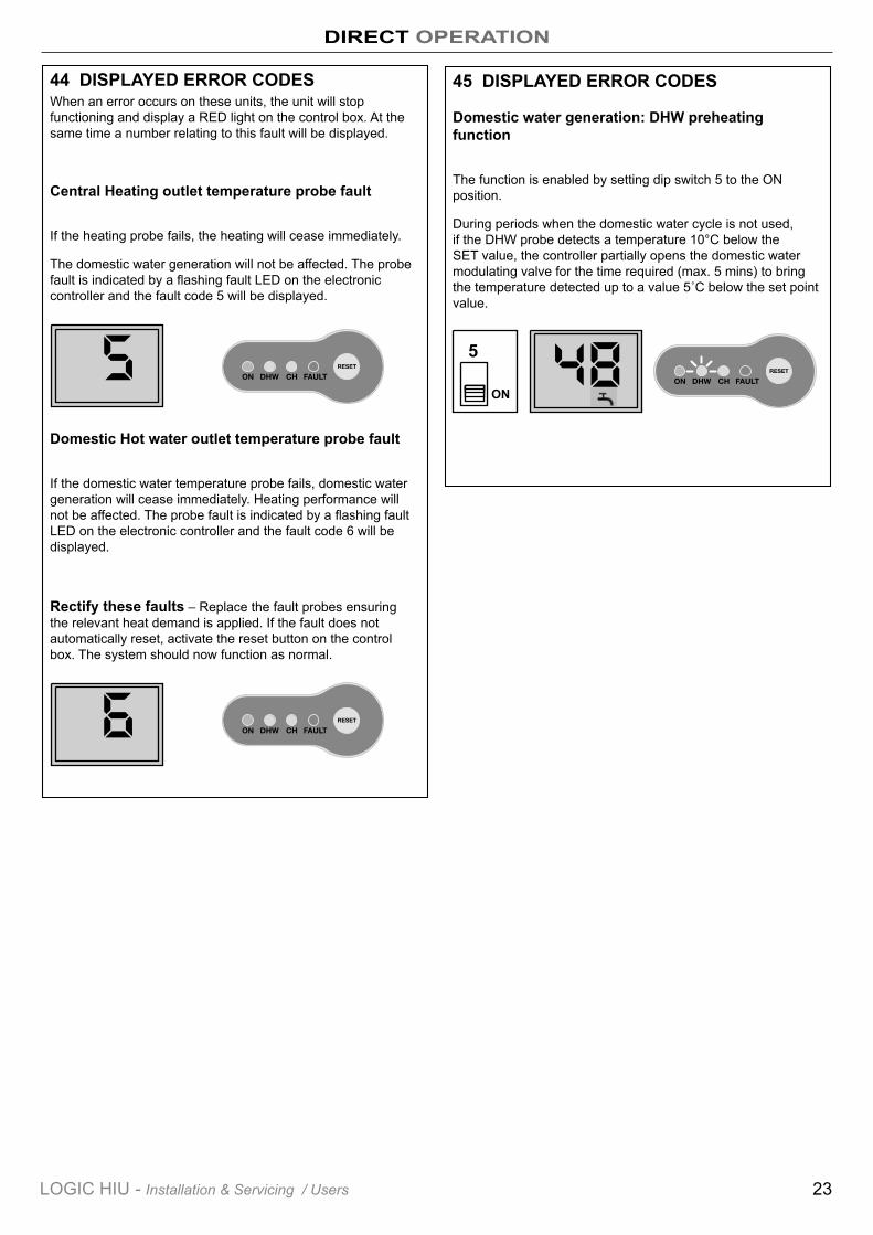
45 DISPLAYED ERROR CODES
Domestic water generation: DHW preheating function
The function is enabled by setting dip switch 5 to the ON position.
During periods when the domestic water cycle is not used, if the DHW probe detects a temperature 10°C below the SET value, the controller partially opens the domestic water modulating valve for the time required (max. 5 mins) to bring the temperature detected up to a value 5˚C below the set point value.
44 DISPLAYED ERROR CODESWhen an error occurs on these units, the unit will stop functioning and display a RED light on the control box. At the same time a number relating to this fault will be displayed.
Central Heating outlet temperature probe fault
If the heating probe fails, the heating will cease immediately.
The domestic water generation will not be affected. The probe fault is indicated by a flashing fault LED on the electronic controller and the fault code 5 will be displayed.
Domestic Hot water outlet temperature probe fault
If the domestic water temperature probe fails, domestic water generation will cease immediately. Heating performance will not be affected. The probe fault is indicated by a flashing fault LED on the electronic controller and the fault code 6 will be displayed.
Rectify these faults – Replace the fault probes ensuring the relevant heat demand is applied. If the fault does not automatically reset, activate the reset button on the control box. The system should now function as normal.
5
ON
INDIRECT & DIRECT HIU UNITS INSTALLATION
24 LOGIC HIU - Installation & Servicing / Users
46 LOCATION OF HIUThe HIU must be installed on a flat and vertical wall, capable of adequately supporting the weight of the boiler and any ancillary equipment supplied in kit form by Ideal Boilers. The HIU must not be fitted outside.
The Logic HIUs are designed for installation in a sheltered domestic environment (or similar), therefore cannot be installed or used outdoors, i.e. in areas directly exposed to atmospheric agents. Outdoor installation may cause malfunctioning and hazards.
If the device is enclosed inside or between cabinets, sufficient space must be provided for routine maintenance procedures. It is recommended that electrical devices are NOT placed underneath the HIU, as they may be damaged in the event of discharge from the safety valve, if it is not connected to a discharge tundish or in the event of leaks occurring at the hydraulic fittings.
The device must not be exposed to water drops or humidity, direct sunlight, the elements, heat sources or high intensity electromagnetic fields.
In the event of a malfunction, fault or incorrect operation, the device should be deactivated; contact a qualified technician for assistance and Isolated from electrical and connection feeds to the unit.
PreparationAfter establishing the position where the HIU will be installed, perform the following operations:
• Mark the holes required for securing the HIU to the wall.• Mark the position of the water pipe connections.
Check the measurements again before installing pipework and electrical cables.
Fix the HIU to the wall.
N.B.: the wall anchors (not supplied) can only guarantee effective support if inserted correctly (in accordance with good technical practice) into walls built using solid or semi-solid bricks. If working with walls built using perforated bricks or blocks, mobile dividing panels or any masonry walls other than those indicated, a preliminary static test must be carried out on the support system.
Hydraulic connections1 Connection to the pipework from the centralised boiler plant2 Connect to heating circuit3 Domestic water circuit connection4 Connect safety relief valve to discharge pipework in
accordance to the local by laws
Electrical1 Electric supply line 230 V (ac) - 50 Hz.2 Time clock/thermostat line (potential-free)3 Centralised bus line for heat meter data transmission
(if required)4 Centralised electric supply line for heat meter (if required)
The whole system should be thoroughly flushed to remove any debris that may be in the supply pipework to the HIU and to the domestic hot water and heating pipework in the apartment before connecting to the HIU.
47 ISOLATION VALVESThese units are supplied with all the necessary isolation valves required for the unit. We recommend that all connections are fitted with isolation valves to allow any maintenance work to be carried out safely and effectively. We would also recommend that the primary system is fitted with the optional flushing bypass valves in addition to the primary isolation valve supplied, immediately upstream of the HIU, to allow the primary system to be flushed prior to the first operation of the unit.
48 ELECTRICAL CONNECTIONSMake sure that the electrical system can withstand the maximum power consumption of the appliance, with particular emphasis on the cross-section of the cables.
If in doubt, contact a qualified technician to thoroughly check the electrical system.
Electrical safety of the appliance is only achieved when it is correctly connected to an effective earthing system, constructed as specified in current safety regulations. This is a compulsory safety requirement.
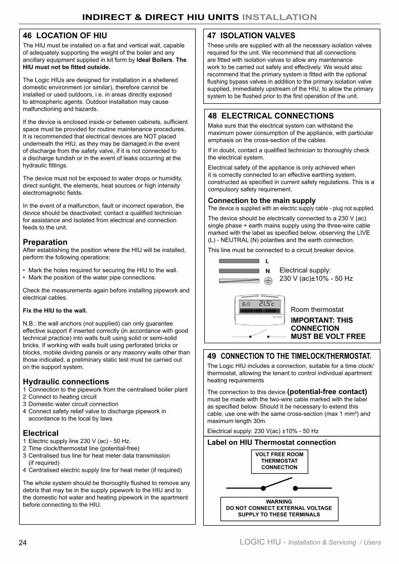
Connection to the main supplyThe device is supplied with an electric supply cable - plug not supplied.
The device should be electrically connected to a 230 V (ac) single phase + earth mains supply using the three-wire cable marked with the label as specified below, observing the LIVE (L) - NEUTRAL (N) polarities and the earth connection.
This line must be connected to a circuit breaker device.
Room thermostat
Electrical supply: 230 V (ac)±10% - 50 Hz
49 CONNECTION TO THE TIMELOCK/THERMOSTAT.The Logic HIU includes a connection, suitable for a time clock/thermostat, allowing the tenant to control individual apartment heating requirements
The connection to this device (potential-free contact) must be made with the two-wire cable marked with the label as specified below. Should it be necessary to extend this cable, use one with the same cross-section (max 1 mm²) and maximum length 30m.
Electrical supply: 230 V(ac) ±10% - 50 Hz
Label on HIU Thermostat connectionVOLT FREE ROOM
THERMOSTAT CONNECTION
WARNINGDO NOT CONNECT EXTERNAL VOLTAGE
SUPPLY TO THESE TERMINALS
IMPORTANT: THIS CONNECTION MUST BE VOLT FREE
INSTALLATION
25LOGIC HIU - Installation & Servicing / Users
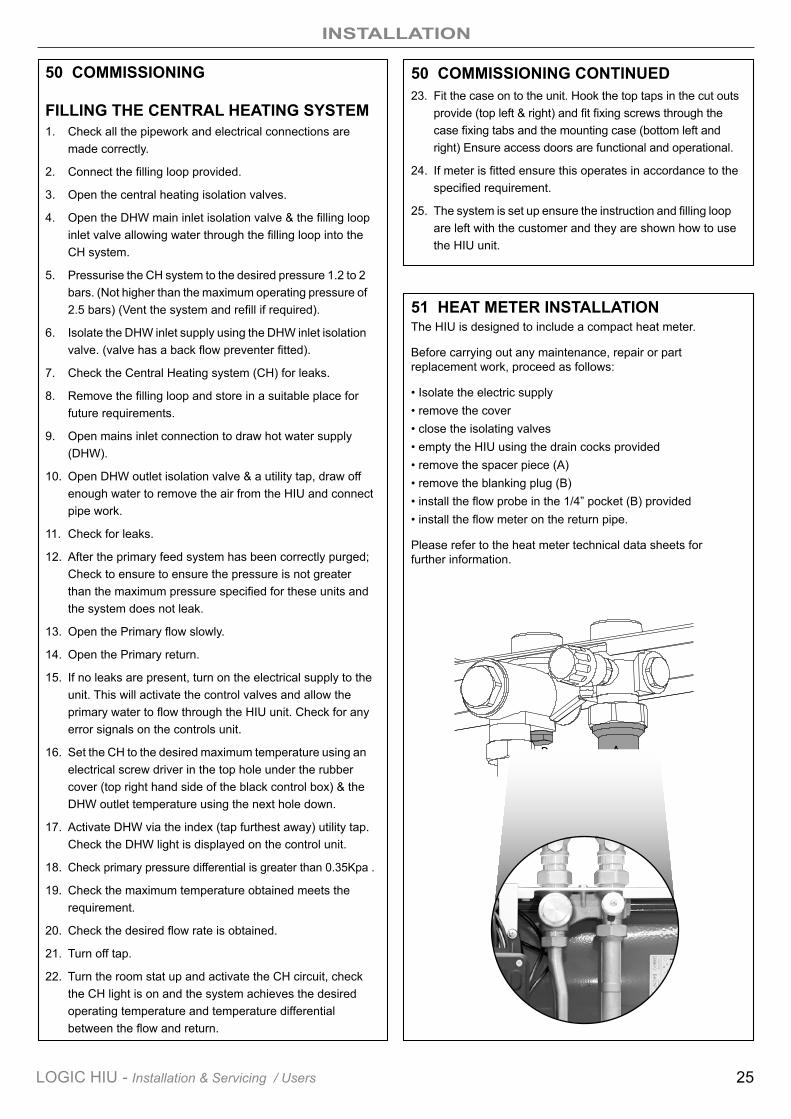
51 HEAT METER INSTALLATIONThe HIU is designed to include a compact heat meter.
Before carrying out any maintenance, repair or part replacement work, proceed as follows:
• Isolate the electric supply• remove the cover • close the isolating valves • empty the HIU using the drain cocks provided • remove the spacer piece (A) • remove the blanking plug (B) • install the flow probe in the 1/4” pocket (B) provided • install the flow meter on the return pipe.
Please refer to the heat meter technical data sheets forfurther information.
50 COMMISSIONING
FILLING THE CENTRAL HEATING SYSTEM1. Check all the pipework and electrical connections are made correctly.
2. Connect the filling loop provided.
3. Open the central heating isolation valves.
4. Open the DHW main inlet isolation valve & the filling loop inlet valve allowing water through the filling loop into the CH system.
5. Pressurise the CH system to the desired pressure 1.2 to 2 bars. (Not higher than the maximum operating pressure of 2.5 bars) (Vent the system and refill if required).
6. Isolate the DHW inlet supply using the DHW inlet isolation valve. (valve has a back flow preventer fitted).
7. Check the Central Heating system (CH) for leaks.
8. Remove the filling loop and store in a suitable place for future requirements.
9. Open mains inlet connection to draw hot water supply (DHW).
10. Open DHW outlet isolation valve & a utility tap, draw off enough water to remove the air from the HIU and connect pipe work.
11. Check for leaks.
12. After the primary feed system has been correctly purged; Check to ensure to ensure the pressure is not greater than the maximum pressure specified for these units and the system does not leak.
13. Open the Primary flow slowly.
14. Open the Primary return.
15. If no leaks are present, turn on the electrical supply to the unit. This will activate the control valves and allow the primary water to flow through the HIU unit. Check for any error signals on the controls unit.
16. Set the CH to the desired maximum temperature using an electrical screw driver in the top hole under the rubber cover (top right hand side of the black control box) & the DHW outlet temperature using the next hole down.
17. Activate DHW via the index (tap furthest away) utility tap. Check the DHW light is displayed on the control unit.
18. Check primary pressure differential is greater than 0.35Kpa .
19. Check the maximum temperature obtained meets the requirement.
20. Check the desired flow rate is obtained.
21. Turn off tap.
22. Turn the room stat up and activate the CH circuit, check the CH light is on and the system achieves the desired operating temperature and temperature differential between the flow and return.
AB
50 COMMISSIONING CONTINUED23. Fit the case on to the unit. Hook the top taps in the cut outs provide (top left & right) and fit fixing screws through the case fixing tabs and the mounting case (bottom left and right) Ensure access doors are functional and operational.
24. If meter is fitted ensure this operates in accordance to the specified requirement.
25. The system is set up ensure the instruction and filling loop are left with the customer and they are shown how to use the HIU unit.
MAINTENANCE
26 LOGIC HIU - Installation & Servicing / Users
B
52 MAINTENANCEAll maintenance procedures should be carried out by an authorised technician.
Regular maintenance guarantees better efficiency and helps to save energy.
Before carrying out any maintenance, repair or part replacement work, proceed as follows:
• Switch off the electric supply• Remove the cover• Close the shut-off valves• Empty the HlU using the drain cocks provided.
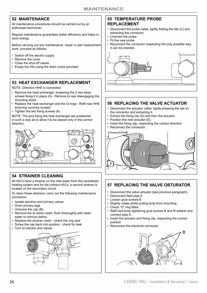
53 HEAT EXCHANGER REPLACEMENTNOTE: Direction HHE is connected• Remove the heat exchanger, loosening the 2 hex head
screws fixing it in place (A) - Remove to rear disengaging the mounting studs
• Replace the heat exchanger and the O-rings - Refit new HHE ensuring correctly located
• Tighten the two fixing screws (A).NOTE: The pins fixing the heat exchanger are positioned in such a way as to allow it to be placed only in the correct direction.
AA
54 STRAINER CLEANINGAll HIU’s have a strainer on the inlet water from the centralised heating system and for the Indirect HIU’s, a second strainer is located on the secondary circuit.To clean these strainers, carry out the following maintenance procedure:• Isolate electrics and primary valves• Drain primary legs• Unscrew the cap (B).• Remove the st rainer mesh, flush thoroughly with clean
water to remove debris.• Replace the strainer mesh - check the ring seal• Screw the cap back into position - check for leak• Turn on electric and valves
B
55 TEMPERATURE PROBE REPLACEMENT• Disconnect the probe cable, lightly folding the tab (C) and
extracting the connector• Unscrew the probe• Fit the new probe• Reconnect the connector respecting the only possible way
it can be inserted.
56 REPLACING THE VALVE ACTUATOR• Disconnect the actuator cable, lightly pressing the tab on
the connector and extracting it.• Extract the fixing clip (D) and then the actuator.• Position the new actuator (E).• Insert the fixing clip, respecting the correct direction• Reconnect the connector.
57 REPLACING THE VALVE OBTURATOR• Disconnect the valve actuator (see previous paragraph).• Disconnect feed pipe A• Loosen grub screws B• Slightly rotate whilst pulling body from mounting.• Check “O” ring fitted.• Refit new body tightening grub screws B and fit washer and
connect pipe A.• Insert the actuator and fixing clip, respecting the correct
position• Reconnect the electrical connector.
C
D
E
F
A
MAINTENANCE
27LOGIC HIU - Installation & Servicing / Users
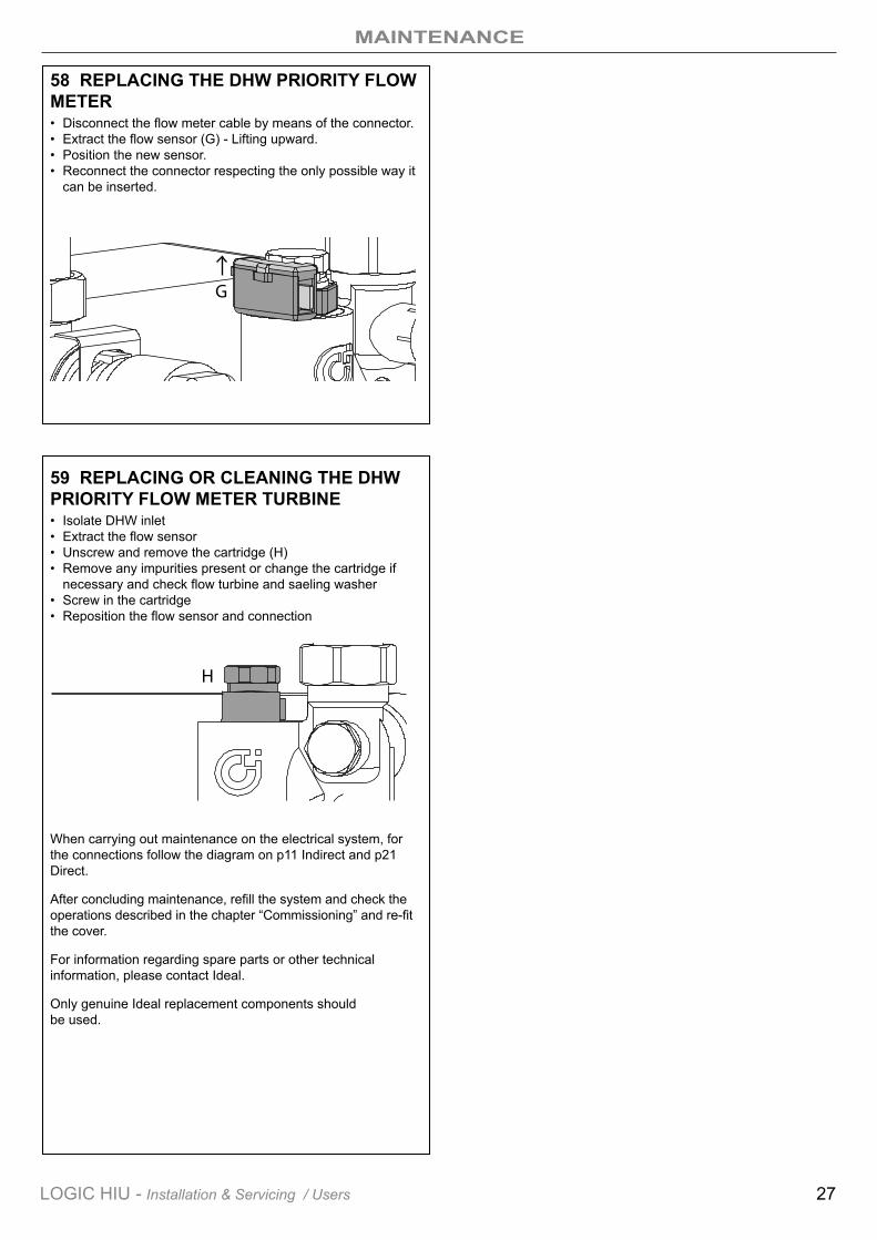
58 REPLACING THE DHW PRIORITY FLOW METER• Disconnect the flow meter cable by means of the connector.• Extract the flow sensor (G) - Lifting upward.• Position the new sensor.• Reconnect the connector respecting the only possible way it
can be inserted.
59 REPLACING OR CLEANING THE DHW PRIORITY FLOW METER TURBINE• Isolate DHW inlet• Extract the flow sensor• Unscrew and remove the cartridge (H)• Remove any impurities present or change the cartridge if
necessary and check flow turbine and saeling washer• Screw in the cartridge• Reposition the flow sensor and connection
When carrying out maintenance on the electrical system, for the connections follow the diagram on p11 Indirect and p21 Direct.
After concluding maintenance, refill the system and check the operations described in the chapter “Commissioning” and re-fit the cover.
For information regarding spare parts or other technical information, please contact Ideal.
Only genuine Ideal replacement components should be used.
G
H
FAULT FINDING
28 LOGIC HIU - Installation & Servicing / Users
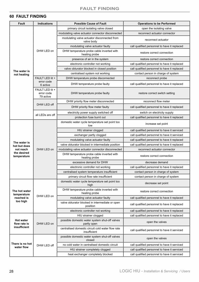
60 FAULT FINDINGFault Indications Possible Cause of Fault Operations to be Performed
The water is not heating
DHW LED on
primary circuit isolating valve closed open the isolating valve
modulating valve actuator connector disconnected reconnect actuator connector
modulating valve actuator disconnected from valve body reconnect actuator
modulating valve actuator faulty call qualified personnel to have it replaced
DHW temperature probe cable inverted with heating probe restore correct connection
presence of air in the system restore correct connection
electronic controller not working call qualified personnel to have it replaced
valve obturator blocked in closed position call qualified personnel to have it replaced
centralised system not working contact person in charge of system
FAULT LED lit + error code 6 active
DHW temperature probe disconnected reconnect probe
DHW temperature probe faulty call qualified personnel to have it replaced
FAULT LED lit + error code 79 active
DHW temperature probe faulty restore correct switch setting
DHW LED offDHW priority flow meter disconnected reconnect flow meter
DHW priority flow meter faulty call qualified personnel to have it replaced
all LEDs are offelectricity power supply switched off switch on electricity supply
protection fuse burnt out call qualified personnel to have it replaced
The water is hot but does
not reach the desired temperature
DHW LED on
domestic water cycle temperature set point too low increase set point
HIU strainer clogged call qualified personnel to have it serviced
exchanger partly clogged call qualified personnel to have it serviced
modulating valve actuator faulty call qualified personnel to have it replaced
valve obturator blocked in intermediate position call qualified personnel to have it replaced
modulating valve actuator connector disconnected reconnect actuator connector
DHW temperature probe cable inverted with heating probe restore correct connection
excessive demand for DHW decrease demand
electronic controller not working call qualified personnel to have it replaced
centralised system temperature insufficient contact person in charge of system
primary circuit flow rate insufficient contact person in charge of system
The hot water temperature reached is too high
DHW LED on
domestic water cycle temperature set point too high decrease set point
DHW temperature probe cable inverted with heating probe restore correct connection
modulating valve actuator faulty call qualified personnel to have it replaced
valve obturator blocked in intermediate or open position call qualified personnel to have it replaced
electronic controller not working call qualified personnel to have it replaced
Hot water flow rate is insufficient
DHW LED on
HIU strainer clogged call qualified personnel to have it replaced
possible domestic water system shut-off valves partly open open the valves
centralised domestic circuit cold water flow rate insufficient call qualified personnel to have it serviced
There is no hot water flow DHW LED off
possible domestic water system shut-off valves closed open the valves
no cold water in centralised domestic circuit call qualified personnel to have it serviced
HIU strainer completely clogged call qualified personnel to have it serviced
heat exchanger completely blocked call qualified personnel to have it serviced
FAULT FINDING
29LOGIC HIU - Installation & Servicing / Users
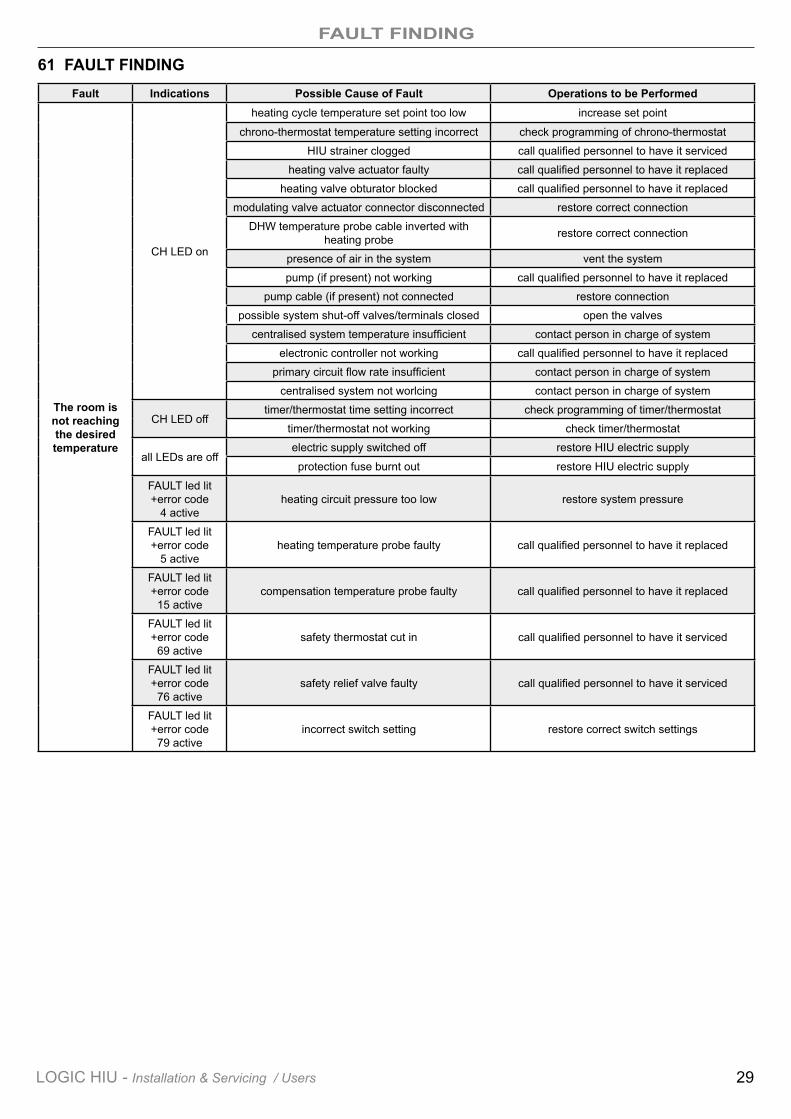
61 FAULT FINDINGFault Indications Possible Cause of Fault Operations to be Performed
The room is not reaching the desired temperature
CH LED on
heating cycle temperature set point too low increase set point
chrono-thermostat temperature setting incorrect check programming of chrono-thermostat
HIU strainer clogged call qualified personnel to have it serviced
heating valve actuator faulty call qualified personnel to have it replaced
heating valve obturator blocked call qualified personnel to have it replaced
modulating valve actuator connector disconnected restore correct connection
DHW temperature probe cable inverted with heating probe restore correct connection
presence of air in the system vent the system
pump (if present) not working call qualified personnel to have it replaced
pump cable (if present) not connected restore connection
possible system shut-off valves/terminals closed open the valves
centralised system temperature insufficient contact person in charge of system
electronic controller not working call qualified personnel to have it replaced
primary circuit flow rate insufficient contact person in charge of system
centralised system not worlcing contact person in charge of system
CH LED offtimer/thermostat time setting incorrect check programming of timer/thermostat
timer/thermostat not working check timer/thermostat
all LEDs are offelectric supply switched off restore HIU electric supply
protection fuse burnt out restore HIU electric supply
FAULT led lit +error code
4 activeheating circuit pressure too low restore system pressure
FAULT led lit +error code
5 activeheating temperature probe faulty call qualified personnel to have it replaced
FAULT led lit +error code
15 activecompensation temperature probe faulty call qualified personnel to have it replaced
FAULT led lit +error code
69 activesafety thermostat cut in call qualified personnel to have it serviced
FAULT led lit +error code
76 activesafety relief valve faulty call qualified personnel to have it serviced
FAULT led lit +error code
79 activeincorrect switch setting restore correct switch settings
NOTES
30 LOGIC HIU - Installation & Servicing / Users

NOTES
31LOGIC HIU - Installation & Servicing / Users
Ideal is a trademark of Ideal Boilers. Registered Office Ideal Boilers Limited National Avenue, Hull, HU5 4JB. Telephone: 01482 492 251 Fax: 01482 448 858Registered in England no. 322137.
Technical Training
Ideal Boilers Limited pursues a policy of continuing improvement in the design and performance of its products. The right is therefore reserved to vary specification without notice.
The Ideal Boilers Technical Training Centre offers a series of first class training courses for domestic, commercial and industrial heating installers, engineers and system specifiers. For details of courses please ring: ................................ 01482 498 432
Logic HIU Customer Support Helpline Tel: 01482 440237www.idealcommercialboilers.com