Embed Size (px)
Citation preview
INSTALLATIONAND SERVICINGIMAX XTRA EL715-1240kW
For Users Guide see reverse of book
When replacing any part on this appliance, use only spare parts that you can beassured conform to the safety and performance specification that we require.Do not use reconditioned or copy parts that have not been clearly authorised by Ideal.
For the very latest copy of literature for specification and maintenance practices visit our website www.idealcommercialboilers.com where you can download the relevant information in PDF format.
May 2016UIN 215012 A02

2 IMAX XTRA EL - Installation & Servicing
GENERAL
CAUTION. To avoid the possibility of injury during the installation, servicing or cleaning of this appliance, care should be taken when handling edges of sheet steel components.
Table 1 Performance Data
Note.
Natural gas consumption is calculated using a calorific value of 37.8MJ/m3 (1038Btu/ft3) gross or 34 MJ/m3 (910 Btu/ft3) nett at 15oC and 1013.25 mbar.a. For l/s, divide the gross heat input (kW) by the gross C.V. of the gas (MJ/m3)b. For ft3/h, divide the gross heat input (Btu/h) by the gross C.V. of the gas (Btu/ft3).c. For Btu's, multiply gross heat input (kW) by 3412 (Btu).
HEALTH & SAFETY DOCUMENT NO. 635The electricity at work regulations, 1989. The manufacturer's notes must NOT be taken, in any way, as overriding statutory obligations.
IMPORTANT. These appliances are CE certified for safety and performance. It is, therefore, important that no external control devices, e.g. flue dampers, economisers etc., are directly connected to these appliances unless covered by these Installation and Servicing Instructions or as otherwise recommended by Ideal Boilers in writing. If in doubt please enquire.Any direct connection of a control device not approved by Ideal Boilers could invalidate the certification and the normal appliance warranty. It could also infringe the Gas Safety Regulations and the above regulations.
Note. Electricity supply and Fuse rating for pumps etc. refer to manufacturer's instructions.
** Optional Headers not fitted
Table 2 General Data
Boiler 715 790 940 1090 1240Boiler output (non-condensing) Mean 70oC
Max kW 666.7 736.6 877.2 1017.2 1156.4Min kW 131.5 145.2 170.4 201.4 229.8
Boiler output (condensing) Mean 40oC
Max kW 722.6 799 951.6 1105.4 1257.8Min kW 147.2 161 191.2 226 255.2
Boiler InputMax Rate
Net kW 681 752.4 895.2 1038 1180Gross kW 755.8 835 993.6 1152 1309.6
Boiler InputMin Rate
Net kW 136.2 150.4 179 207.6 236Gross kW 151.2 167 198.6 230.4 262
Maximum Gas Rate m3/h 72 79.6 94.8 109.8 124.4Approx. flue gas volume80/60ºC i.e. non-condensing
@ Max. Rate m3/h 1055.9 1166.6 1388 1609.4 1829.6@ Min. Rate m3/h 212.6 234.8 279.2 324 368.4
Approx. flue gas temps 50/30ºC
@ Max. Rate ºC 43@ Min. Rate ºC 31
Approx. flue gas temps 80/60ºC
@ Max. Rate ºC 63@ Min. Rate ºC 50
Max. Flue Resistance Pa 100Flue Gas CO2G20/LNG
@ Max Rate % 9.5@ Min. Rate % 9
Maximum Flue Temperature ºC 100NOx with O2 = 0% mg/kWh <40
Class 6Boiler Efficiency Full Load 80/60ºC % 97.9 97.9 98 98 98Boiler Efficiency Part Load % 109.7 109.7 109.8 109.8 109.8Boiler Efficiency Full Load 50/30ºC % 106.1 106.2 106.3 106.5 106.6Seasonal Boiler Efficiency (Building Regs L2) Gross % 96.8 96.8 96.9 96.9 97
Boiler 715 790 940 1090 1240Gas Supply Pressure mbar 20Gas Supply Connection R (in BSP) 2" (x2) **Flow Connection 3" - DN80 - PN6 **Max. Flow Temperature ºC 90Return Connection 3" - DN80 - PN6 **Hydraulic Resistance @ ΔT 20ºC mbar 102.9 100.8 98.7 97.65 96.6Max System Pressure bar (psi) 6 (87)Boiler Electrical Supply 230v - 50HzBoiler Fuse Rating A Master Module 7A - Slave Module 7APower Consumption (Boiler Only) W 1202 1184 1340 1250 1540Power Consumption - Standby (Boiler Only) W 8Air Inlet Ø mm 200 (x2) ** Flue Size Ø mm 303 ±1 303 ±1 303 ±1 353 ±1 353 ±1Condensate Drain mm 21.5 (x2)Noise Power Levels dBA <60Boiler Weight (Packaged) ** kg (lb) 925 (2039) 959 (2114) 1015 (2238) 1073 (2366) 1113 (2454)Boiler Weight (Unpackaged Dry) ** kg (lb) 918 (2024) 952 (2099) 1008 (2222) 1066 (2350) 1106 (2438)Water content litres ( gal) 94.6 (20.8) 106.6 (23.4) 118.6 (26) 130.6 (28.8) 150.6 (33.2)

3IMAX XTRA EL - Installation & Servicing
GENERAL
CONTENTSBoiler Assembly - Exploded View ..................................15
Boiler Clearances. ...........................................................12
Boiler Dimensions. .......................................................8-11
Commissioning and Testing. ..........................................37
Electrical Connections. ...................................................23
Electrical Supply. ...............................................................6
Fault Finding. ..............................................................52-61
Flue / Air Duct Installation .........................................19-21
Gas Safety Regulations ...................................................4
Gas Supply. ........................................................................4
Hydraulic Resistance. .......................................................7
Initial Lighting. .................................................................37
Installation. ..................................................................15-39
Option Kits. ........................................................................4
Performance Data. .............................................................2
Replacement of Parts .................................................46-51
Servicing. ....................................................................40-51
Short List of Parts. ..........................................................62
Transporting & Positioning the Boiler. .....................16-17
Ventilation. .......................................................................13
Water Circulation. ..............................................................5
Water Treatment. ...............................................................6
Wiring Diagrams. ........................................................28-29
Key to symbolsGB = United Kingdom (Countries of
destination)IE = Ireland (Countries of destination)PMS = Maximum operating pressure of
waterB23 = An appliance intended to be
connected to a flue which evacuates the products of combustion to the outside of the room containing the boiler. The combustion air is drawn directly from the room. The fan is up stream of the combustion chamber.
C53 = A room sealed appliance which is connected via its separate ducts to two terminals that may terminate in zones of different pressure.
NOTE TO THE INSTALLER: COMPLETE THE COMMISSIONING REPORT AND LEAVE THESE INSTRUCTIONS WITH APPLIANCE
IMAX XTRA EL715, 790, 940, 1090, 1240
P.I. No. 86 CQ 47 Natural Gas onlyDestination Countries: GB, IE
MASTER MODULESLAVE MODULE
C63 = A room sealed appliance intended to be connected to a separately approved and marketed system for the supply of combustion air and discharge of combustion products.
The fan is up stream of the combustion chamber. Condensate flow from the flue is not permitted back into the appliance. The maximum allowable temperature of incoming combustion air for C63
type flue is 40ºC. Terminals for the supply of combustion air and for evacuation of combustion
products shall not be installed on opposite walls of the building. The maximum allowable re-circulation rate is 10%.
4 IMAX XTRA EL - Installation & Servicing
GENERAL
INTRODUCTIONThe IMAX XTRA EL boilers are fully automatically controlled, floor standing, fanned, high efficiency condensing appliances.The appliance comprises of two boiler modules.The comprehensive boiler controls built into the appliance include:- Volt free 'alarm' contacts (lockout)- Volt free 'boiler run' contacts- Burner hours run meters- System temperaturesThe boilers can draw their combustion air from the room or via ducting from outside.
Through a sophisticated control system combined with premix burner technology and an aluminium heat exchanger, the boilers are capable of high operating efficiencies and low emissions.
These boilers are certified to meet the requirements of the EC Gas Appliance Directive, Boiler Efficiency Directive, EMC, Low Voltage Directive and Energy Related Products Directive.
OPTIONAL EXTRA KITS• Modulating Sequencer Kit - DHW Tank Kit (used with modulating Sequencer) - Plant Room Sensor Kit (used with modulating Sequencer) - 6 Zone Expansion Kit (used with modulating Sequencer)• Programmable Room Thermostat Kit (for use with boiler &
modulating Sequencer)• Programmable Room Thermostat Kit (for use with boiler only)• Outside Sensor Kit• DHW Tank Sensor Kit• Safety Interlock Kit• BACNet Gateway Kit• LONWorks Gateway Kit• MODBus Gateway Kit• Remote Access Kit• Sealed System Services Flow Manifold Kit (x 2 req'd)• Inlet Air Filter Kit (x 2 req'd)• Condensate Pump Kit (x 2 req'd)• Room Sealed Air Duct Kit (x 2 req'd)• Header Kit (flow/return)• Header Kit (Gas)• Header Kit (air)• 300-350mm Flue Increaser (715kW, 790kW & 940kW only)
SAFETYCurrent Gas Safety (Installation and Use) Regulations or rules in forceThe appliance is suitable only for installation in GB and IE and should be installed in accordance with the rules in force.In GB, the installation must be carried out by a GAS SAFE Registered Installer or in IE by a competent person. It must be carried out in accordance with the relevant requirements of the:• Gas Safety (Installation and Use) Regulations• The appropriate Building Regulations either The Building
Regulations, The Building Regulations (Scotland), Building Regulations (Northern Ireland).
• The Water Fittings Regulations or Water byelaws in Scotland.• The Current I.E.E. Wiring Regulations.Where no specific instructions are given, reference should be made to the relevant British Standard Code of Practice.In IE, the installation must be carried out by a Competent Person
and installed in accordance with the current Building Regulations and reference should be made to the current ETCI rules for electrical installation.The boilers have been tested and certified by BSI to EN 15502 for use with Natural Gas.Detailed recommendations are contained in the following Standards and Codes of Practice:BS. 5854 Flue and flue Structures in Buildings.BS. 6644 Installation of gas fired hot water boilers of rated
inputs between 70kW and 1.8MW (net) (2nd and 3rd family gases).
BS. 6880 Low temperature hot water heating systems of output greater than 45kW.
Part 1 Fundamental and design considerations. Part 2 Selection of equipment. Part 3 Installation, commissioning and maintenance.IGE/UP/1 Soundness testing and purging of industrial and
commercial gas installations.IGE/UP/2 Gas installation pipework, boosters and compressors
on industrial and commercial premises.IGE/UP/10 Installation of gas appliances in industrial and
commercial premises.
SAFE HANDLING OF SUBSTANCESNo asbestos, mercury or CFCs are included in any part of the boiler or its manufacture.
FOUNDATION / LOCATION OF BOILERThe boiler must stand on a floor which must be flat, level and of a suitable load bearing capacity to support the weight of the boiler (when filled with water) and any ancillary equipment.Ideally the boiler should be placed on a plinth exceeding the plan area of the boiler by 75mm on each side and at least 100mm high.
The boiler must not be fitted outside.
GAS SUPPLYThe local gas supplier should be consulted, at the installation planning stage, in order to establish the availability of an adequate supply of gas. An existing service pipe must NOT be used without prior consultation with the local gas supplier.A gas meter can only be connected by the local gas supplier or by a registered GAS SAFE engineer or in IE by a competent person.An existing meter should be checked, preferably by the gas supplier, to ensure that the meter is adequate to deal with the rate of gas supply required. A minimum working gas pressure of 15mbar MUST be available at the boiler inlet for Natural gas.Do not use pipes of smaller size than the boiler inlet gas connection.The complete installation MUST be tested for gas soundness and purged in accordance with the appropriate standards.Gas BoostersA gas booster is required if the gas pressure available at the boiler is lower than that required by the boiler manufacturer to attain the flow rate for maximum burner input rating.Location of the booster requires careful consideration but should preferably be closer to the burner rather than the gas meter. Ventilation should also be considered to ensure that ambient temperatures do not exceed designed recommendations. Further guidance is provided in IGE/UP/2.

5IMAX XTRA EL - Installation & Servicing
GENERAL
FLUE INSTALLATIONThe appropriate Ideal Flue Header Kit must be fitted to these boilers.IMPORTANT. It is the responsibility of the installer to ensure, in practice, that products of combustion discharging from the terminal cannot re-enter the building or any other adjacent building through ventilators, windows, doors, other sources of natural air infiltration, or forced ventilation / air conditioning.If this should occur the appliance MUST be isolated from the gas supply and labelled as 'unsafe' until corrective action can be taken.Terminal PositionDue to the high efficiency of the boilers pluming will occur. Vertical termination is recommended and terminal positions which could cause problems should be avoided. Particular care should be taken in the case of large output boiler installations, and complying with the requirements of the Clean Air Act.The flue must be installed in accordance with the appropriate Building Regulations and standards listed on page 4 and in compliance with BS6644. In IE refer to I.S.820:2000.
FLUE SYSTEM DESIGNDue to the high efficiency of these boilers, the flue gas temperatures are low and the buoyancy in the stack will be relatively small. The boiler is supplied with an integral fan which is fully matched to the boiler in each case to provide correct combustion air flow and overcome the flue resistance.
The power of this fan is such that there is a large reserve of pressure available to overcome a significant length of flue without affecting the combustion performance of the boiler. The maximum & minimum pressure available measured at the base of the flue to overcome combined flue and air resistance is 100Pa (max) and -10Pa (min) for all model sizes. The pressure should be checked at maximum heat input to ensure this maximum pressure is not exceeded. Care should be taken with tall flue systems to ensure excess buoyancy is not created. A negative pressure must not be created at the boiler flue outlet.
Boiler Size 715 790 940 1090 1240Flue Pressure (max) Pa 100
Flue Pressure (min) Pa -10
The addition of elbows and their positions in the flue and the terminal will have a significant effect on the maximum flue length. Consult with your flue supplier for detailed design work.
IMPORTANT NOTE. If combustion air is drawn from within the boiler room, ensure no dust or airborne debris can be ingested into the appliance. Dusty concrete flooring should be sealed to reduce the presence of dust. Ideally where possible duct the air supply into the boiler room from a clean source outside the boiler room/building.If the air filter accessories are fitted the 100Pa / - 10Pa pressure requirement must be checked at maximum heat input with the filter fitted.
MaterialWith no requirement for buoyancy to discharge flue products and with low flue gas temperatures, single wall flues are suitable for most installations. Care should still be taken to maintain compliance with building regulations and relevant standards.Care should also be taken in the selection of flue terminals as these tend to accentuate the formation of a plume and could freeze in cold weather conditions and can cause added flue resistance.
Care should be taken to ensure the specification of the chimney is suitable for the application by reference to the manufacturer's literature.
WATER CIRCULATION SYSTEMThe boiler is suitable for connection to a sealed heating system or an open vented system.
Ideal Boilers recommend that the boiler be installed on a reverse return system.
A circulation pump MUST be connected to the boiler, see below.
The boiler must NOT be used for direct hot water supply. The hot water storage cylinder MUST be of the indirect type.
Single feed, indirect cylinders are not recommended and MUST NOT be used on sealed systems.
The appliances are NOT suitable for gravity central heating nor are they suitable for the provision of gravity domestic hot water.
The hot water cylinder and ancillary pipework, not forming part of the useful heating surface, should be lagged to prevent heat loss and any possible freezing - particularly where pipes run through roof spaces and ventilated under floor spaces.
The boiler must be vented. There must be no low points between the boiler flow connection and a system vent point, which should be positioned as close as practically possible to the boiler flow connection.
Draining taps MUST be located in accessible positions, which permit the draining of the whole system - including the boiler and hot water storage vessel. They should be at least 1/2" BSP nominal size and be in accordance with BS. 2879. Do not use the boiler drain tap to drain the system as this can induce sludge into the heat exchanger.
The central heating system should be in accordance with the relevant standards listed on page 4.
Once the burner has extinguished the boiler requires a 2 minute pump overrun to dissipate the residual heat. In order to allow this a 2 minute pump overrun is incorporated into the boiler control.
An external pump must be connected or controlled by the boiler, however if it is directly connected it must not exceed 1.3A inductive load, if it does then a relay or contactor must be used.
Flue Products/Flue PressureSamplingPoint
6 IMAX XTRA EL - Installation & Servicing
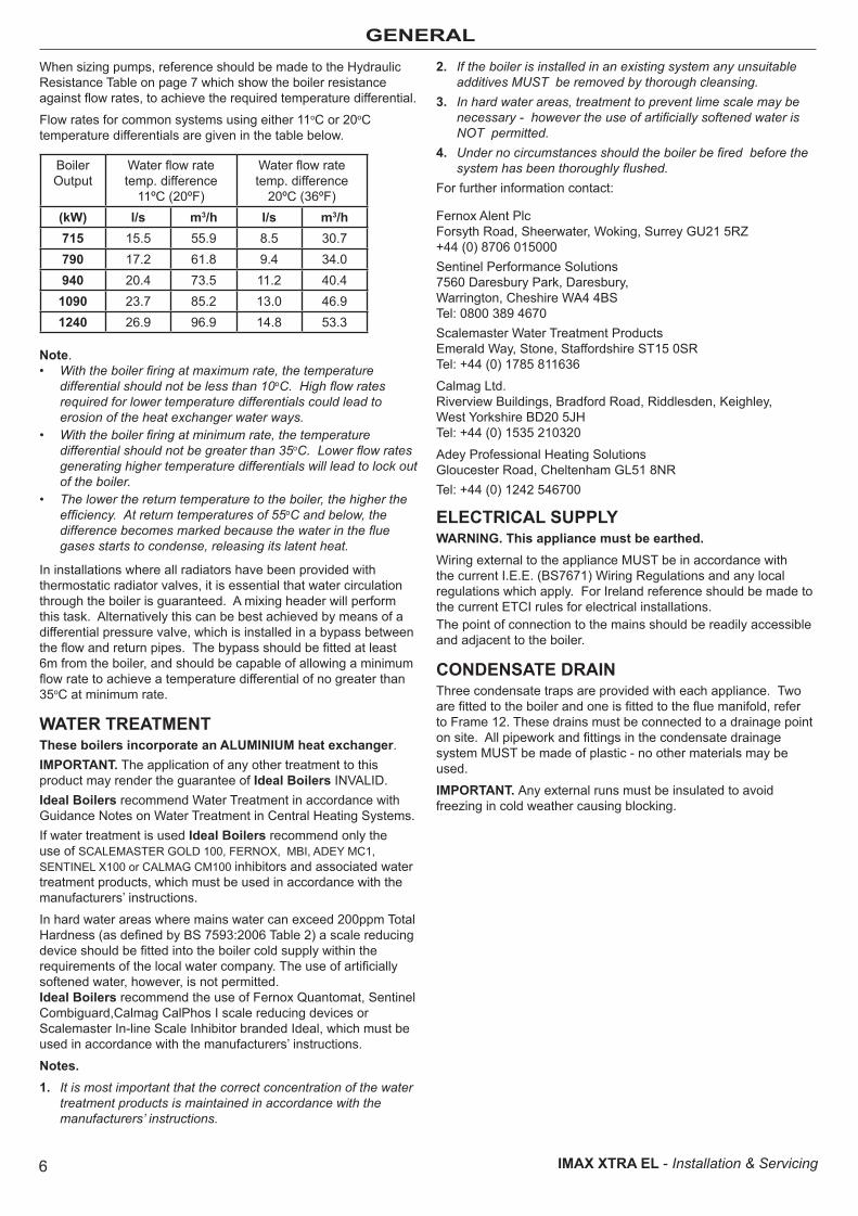
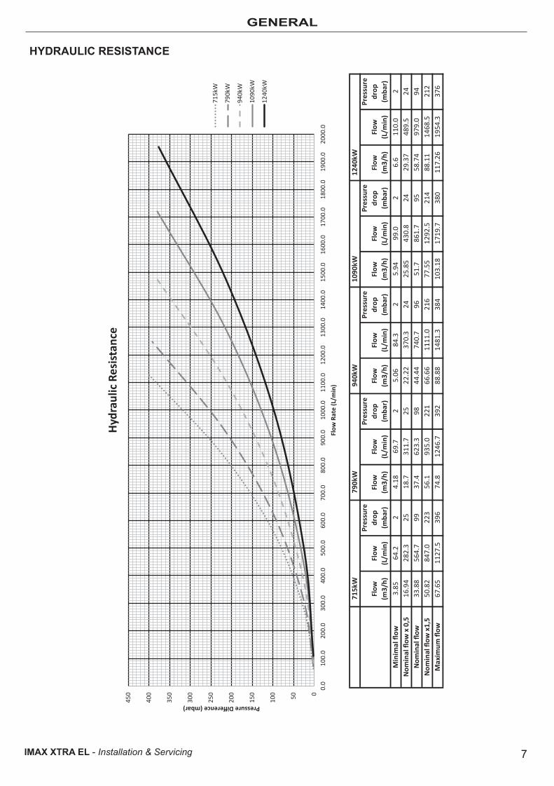
GENERALWhen sizing pumps, reference should be made to the Hydraulic Resistance Table on page 7 which show the boiler resistance against flow rates, to achieve the required temperature differential.
Flow rates for common systems using either 11oC or 20oC temperature differentials are given in the table below.
Boiler Output
Water flow rate temp. difference
11ºC (20ºF)
Water flow rate temp. difference
20ºC (36ºF)(kW) l/s m3/h l/s m3/h715 15.5 55.9 8.5 30.7790 17.2 61.8 9.4 34.0940 20.4 73.5 11.2 40.4
1090 23.7 85.2 13.0 46.91240 26.9 96.9 14.8 53.3
Note.• With the boiler firing at maximum rate, the temperature
differential should not be less than 10oC. High flow rates required for lower temperature differentials could lead to erosion of the heat exchanger water ways.
• With the boiler firing at minimum rate, the temperature differential should not be greater than 35oC. Lower flow rates generating higher temperature differentials will lead to lock out of the boiler.
• The lower the return temperature to the boiler, the higher the efficiency. At return temperatures of 55oC and below, the difference becomes marked because the water in the flue gases starts to condense, releasing its latent heat.
In installations where all radiators have been provided with thermostatic radiator valves, it is essential that water circulation through the boiler is guaranteed. A mixing header will perform this task. Alternatively this can be best achieved by means of a differential pressure valve, which is installed in a bypass between the flow and return pipes. The bypass should be fitted at least 6m from the boiler, and should be capable of allowing a minimum flow rate to achieve a temperature differential of no greater than 35oC at minimum rate.
WATER TREATMENTThese boilers incorporate an ALUMINIUM heat exchanger.IMPORTANT. The application of any other treatment to this product may render the guarantee of Ideal Boilers INVALID.Ideal Boilers recommend Water Treatment in accordance with Guidance Notes on Water Treatment in Central Heating Systems.If water treatment is used Ideal Boilers recommend only the use of SCALEMASTER GOLD 100, FERNOX, MBI, ADEY MC1, SENTINEL X100 or CALMAG CM100 inhibitors and associated water treatment products, which must be used in accordance with the manufacturers’ instructions.
In hard water areas where mains water can exceed 200ppm Total Hardness (as defined by BS 7593:2006 Table 2) a scale reducing device should be fitted into the boiler cold supply within the requirements of the local water company. The use of artificially softened water, however, is not permitted. Ideal Boilers recommend the use of Fernox Quantomat, Sentinel Combiguard,Calmag CalPhos I scale reducing devices or Scalemaster In-line Scale Inhibitor branded Ideal, which must be used in accordance with the manufacturers’ instructions.
Notes.1. It is most important that the correct concentration of the water
treatment products is maintained in accordance with the manufacturers’ instructions.
2. If the boiler is installed in an existing system any unsuitable additives MUST be removed by thorough cleansing.
3. In hard water areas, treatment to prevent lime scale may be necessary - however the use of artificially softened water is NOT permitted.
4. Under no circumstances should the boiler be fired before the system has been thoroughly flushed.
For further information contact:
Fernox Alent Plc Forsyth Road, Sheerwater, Woking, Surrey GU21 5RZ+44 (0) 8706 015000Sentinel Performance Solutions 7560 Daresbury Park, Daresbury, Warrington, Cheshire WA4 4BS Tel: 0800 389 4670Scalemaster Water Treatment Products Emerald Way, Stone, Staffordshire ST15 0SR Tel: +44 (0) 1785 811636
Calmag Ltd. Riverview Buildings, Bradford Road, Riddlesden, Keighley, West Yorkshire BD20 5JH Tel: +44 (0) 1535 210320
Adey Professional Heating SolutionsGloucester Road, Cheltenham GL51 8NRTel: +44 (0) 1242 546700
ELECTRICAL SUPPLYWARNING. This appliance must be earthed.Wiring external to the appliance MUST be in accordance with the current I.E.E. (BS7671) Wiring Regulations and any local regulations which apply. For Ireland reference should be made to the current ETCI rules for electrical installations.The point of connection to the mains should be readily accessible and adjacent to the boiler.
CONDENSATE DRAINThree condensate traps are provided with each appliance. Two are fitted to the boiler and one is fitted to the flue manifold, refer to Frame 12. These drains must be connected to a drainage point on site. All pipework and fittings in the condensate drainage system MUST be made of plastic - no other materials may be used.
IMPORTANT. Any external runs must be insulated to avoid freezing in cold weather causing blocking.
7IMAX XTRA EL - Installation & Servicing
GENERAL
HYDRAULIC RESISTANCE
715k
W79
0kW
940k
W10
90kW
1240
kW
Flow
(m
3/h)
Flow
(L
/min
)
Pres
sure
dr
op
(mba
r)Fl
ow
(m3/
h)Fl
ow
(L/m
in)
Pres
sure
dr
op
(mba
r)Fl
ow
(m3/
h)Fl
ow
(L/m
in)
Pres
sure
dr
op
(mba
r)Fl
ow
(m3/
h)Fl
ow
(L/m
in)
Pres
sure
dr
op
(mba
r)Fl
ow
(m3/
h)Fl
ow
(L/m
in)
Pres
sure
dr
op
(mba
r)M
inim
al flow
3.85
64.2
24.18
69.7
25.06
84.3
25.94
99.0
26.6
110.0
2N
omin
al flow
x 0
,516
.94
282.3
2518
.731
1.7
2522
.22
370.3
2425
.85
430.8
2429
.37
489.5
24N
omin
al flow
33.88
564.7
9937
.462
3.3
9844
.44
740.7
9651
.786
1.7
9558
.74
979.0
94N
omin
al flow
x1,
550
.82
847.0
223
56.1
935.0
221
66.66
1111
.021
677
.55
1292
.521
488
.11
1468
.521
2M
axim
um flow
67.65
1127
.539
674
.812
46.7
392
88.88
1481
.338
410
3.18
1719
.738
011
7.26
1954
.337
6
050100
150
200
250
300
350
400
450
0.0
100.0
200.0
300.0
400.0
500.0
600.0
700.0
800.0
900.0
1000
.011
00.0
1200
.013
00.0
1400
.015
00.0
1600
.017
00.0
1800
.019
00.0
2000
.0
Pressure Difference (mbar)
Flow
Rat
e (L
/min
)
Hyd
raul
ic R
esis
tanc
e
715kW
790kW
940kW
1090
kW
1240
kW
8 IMAX XTRA EL - Installation & Servicing
GENERAL
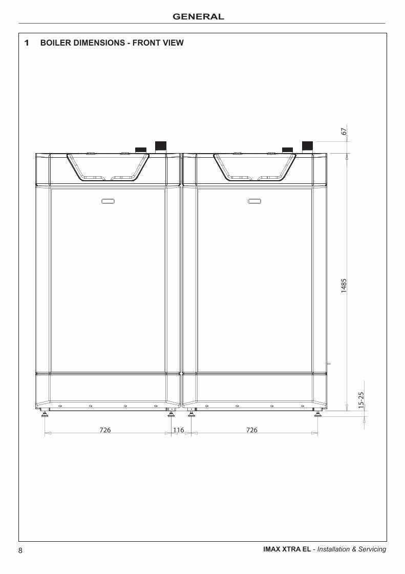
1 BOILER DIMENSIONS - FRONT VIEW
67
726 116 726
1485
15-2
5

9IMAX XTRA EL - Installation & Servicing
GENERAL
2 BOILER DIMENSIONS - SIDE VIEW
694
1392
136
MAG3/4"
ST 2"
10 IMAX XTRA EL - Installation & Servicing
GENERAL
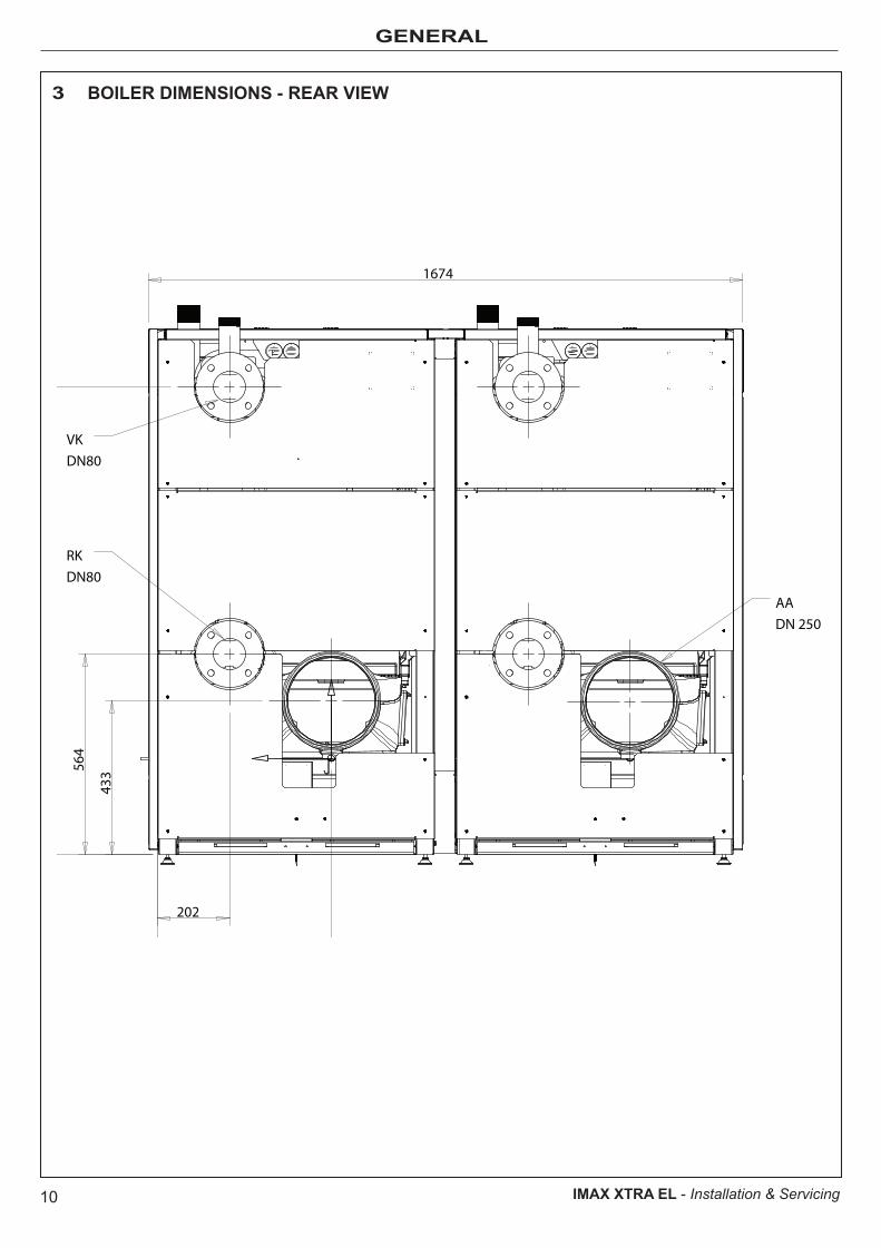
3 BOILER DIMENSIONS - REAR VIEW
1674
564
1318
202
488
433
AADN 250
VKDN80
RKDN80
11IMAX XTRA EL - Installation & Servicing
GENERAL
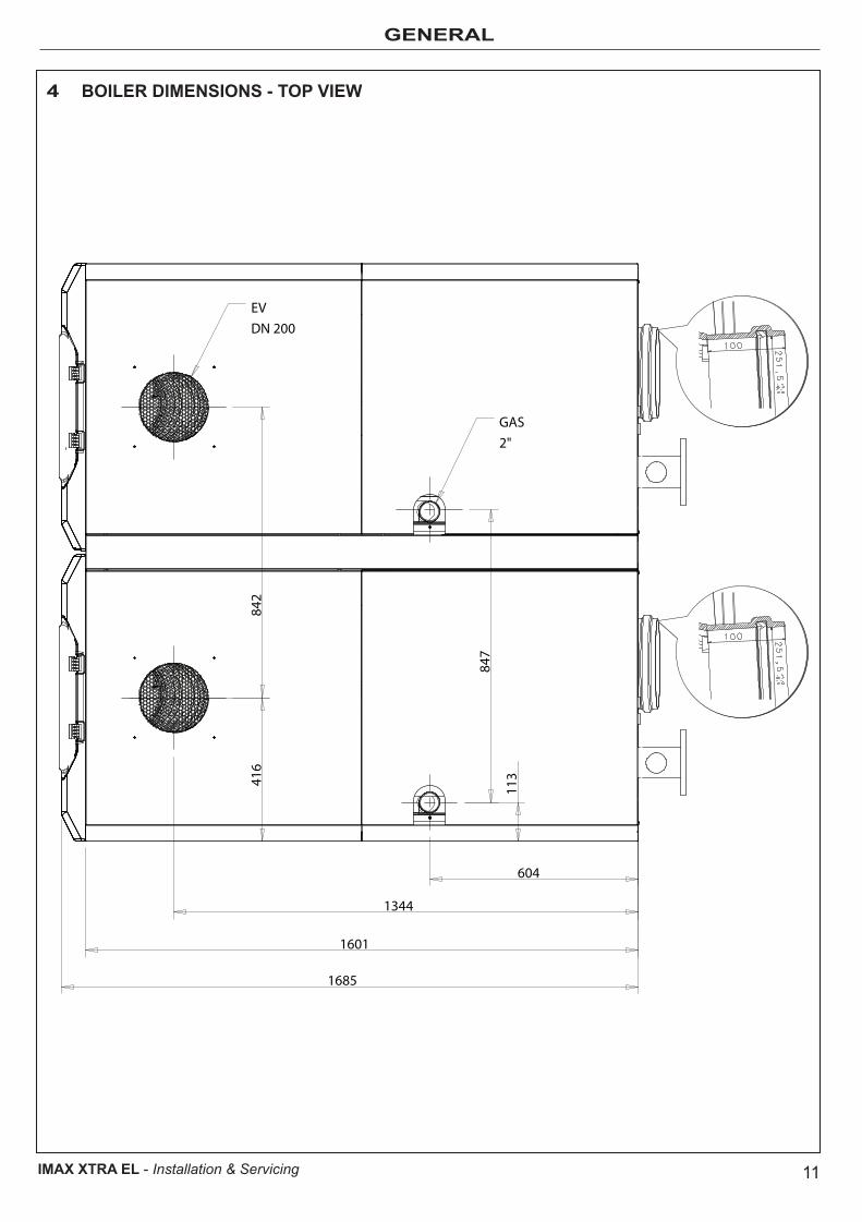
4 BOILER DIMENSIONS - TOP VIEW
604
1344
1601
1685
416
842
113
847
GAS2"
EVDN 200

12 IMAX XTRA EL - Installation & Servicing
GENERAL
5 BOILER CLEARANCES
DimensionABCD
TOP
Minimum700700
1000700700
Recommended10001000120010001000
D
C
B
A
13IMAX XTRA EL - Installation & Servicing
GENERAL
7 SEALED SYSTEM REQUIREMENTSWorking pressure 6 bar maximum.Particular reference should be made to BS. 6644 and Guidance note PM5 "Automatically controlled steam and hot water boilers" published by the Health and Safety Executive.
The information and guidance given below is not intended to override any requirements of either of the above publications or the requirements of the local authority, gas or water undertakings.
In general commercial closed pressurised systems are provided with either manual or automatic water make up.
In both instances it will be necessary to fit automatic controls intended to protect the boiler, circulating system and ancillary equipment by shutting down the boiler plant if a potentially hazardous situation should arise.
Examples of such situations are low water level and operating pressure or excessive pressure within the system. Depending on circumstances, controls will need to be either manual or automatic reset. In the event of a shutdown both visual and audible alarms may be necessary.
Expansion vessels used must comply with BS. 4814 and must be sized on the basis of the total system volume and initial charge pressure.
Initial minimum charge pressure should not be less than 1.0 bar (15psi) and must take account of the static head and specification of the pressurising equipment. The maximum water temperatures permissible at the point of minimum pressure in the system are specified in BSEN 61508.
When make up water is not provided automatically it will be necessary to fit controls which shut down the plant in the event of the maximum system pressure approaching to within 0.35bar (5psi) of the safety valve setting.
Other British Standards applicable to commercial sealed systems are:
BS. 6880: Part 2BS. 1212BS. 6281: Part 1BS. 6282: Part 1BS. 6283: Part 4
6 VENTILATION
The ventilation requirements of these boilers are dependant on the type of flue system used, and their heat input. All vents must be permanent with no means of closing, and positioned to avoid accidental obstructions by blocking or flooding.
Detailed reference should be made to BS. 6644 for inputs between 70kW and 1.8MW (net). In IE refer to the current edition of I.S.820. The following notes are for general guidance only:
Dust contamination in the combustion air may cause blockage of the burner slots. Unless the boiler room provides a dust free environment then direct connection of the air intake via ducting to clean outside air should be used.The temperature within a boiler room shall not exceed 25oC within 100 mm of the floor, 32oC at mid height and 40oC within 100 mm of the ceiling.
IMPORTANT NOTE.If combustion air is drawn from within the boiler room, ensure no dust or airborne debris can be ingested into the appliance. Dusty concrete flooring should be sealed to reduce the presence of dust. Ideally where possible duct the air supply into the boiler room from a clean source outside the boiler room/building.
Open Flued InstallationsIf ventilation is to be provided by means of permanent high and low vents communicating direct with outside air, then reference can be made to the sizes below. For other ventilation options refer to BS. 6644. In IE refer to the current edition of I.S.820.
Required area (cm2) per kW of total rated input (net)
Boiler Room Enclosure
Low level (inlet) 4 10
High level (outlet) 2 5
Note: Where a boiler installation is to operate in summer months (e.g. DHW) additional ventilation requirements are stated, if operating for more than 50% of time (refer to BS6644).
IMPORTANT; If a sealed system is required please ensure a maximum flow temperature of 90ºC is not exceeded.
14 IMAX XTRA EL - Installation & Servicing
GENERAL
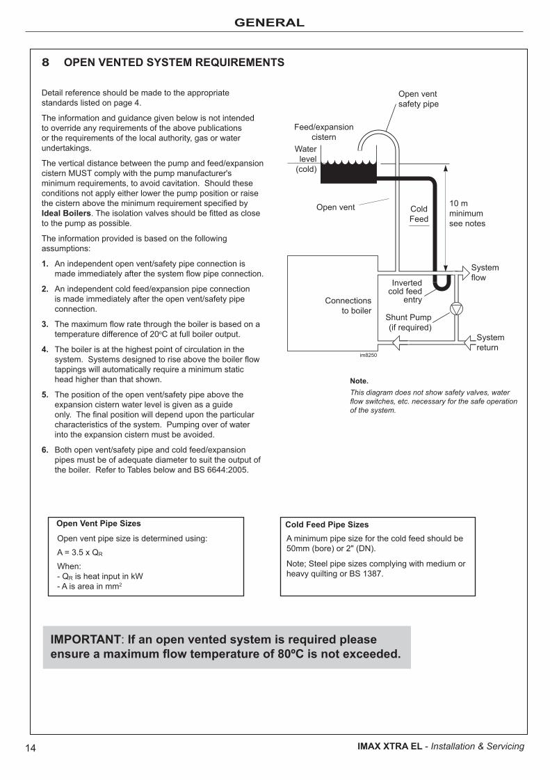
Detail reference should be made to the appropriate standards listed on page 4.
The information and guidance given below is not intended to override any requirements of the above publications or the requirements of the local authority, gas or water undertakings.
The vertical distance between the pump and feed/expansion cistern MUST comply with the pump manufacturer's minimum requirements, to avoid cavitation. Should these conditions not apply either lower the pump position or raise the cistern above the minimum requirement specified by Ideal Boilers. The isolation valves should be fitted as close to the pump as possible.
The information provided is based on the following assumptions:
1. An independent open vent/safety pipe connection is made immediately after the system flow pipe connection.
2. An independent cold feed/expansion pipe connection is made immediately after the open vent/safety pipe connection.
3. The maximum flow rate through the boiler is based on a temperature difference of 20oC at full boiler output.
4. The boiler is at the highest point of circulation in the system. Systems designed to rise above the boiler flow tappings will automatically require a minimum static head higher than that shown.
5. The position of the open vent/safety pipe above the expansion cistern water level is given as a guide only. The final position will depend upon the particular characteristics of the system. Pumping over of water into the expansion cistern must be avoided.
6. Both open vent/safety pipe and cold feed/expansion pipes must be of adequate diameter to suit the output of the boiler. Refer to Tables below and BS 6644:2005.
8 OPEN VENTED SYSTEM REQUIREMENTS
Note.This diagram does not show safety valves, water flow switches, etc. necessary for the safe operation of the system.
Open Vent Pipe Sizes Cold Feed Pipe Sizes
IMPORTANT: If an open vented system is required please ensure a maximum flow temperature of 80ºC is not exceeded.
Open vent pipe size is determined using:
A = 3.5 x QR
When:- QR is heat input in kW- A is area in mm2
A minimum pipe size for the cold feed should be 50mm (bore) or 2" (DN).
Note; Steel pipe sizes complying with medium or heavy quilting or BS 1387.
15
INSTALLATION
IMAX XTRA EL - Installation & Servicing
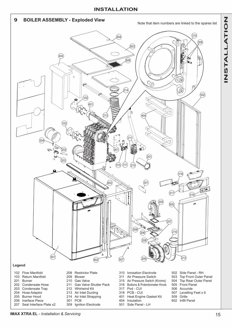
9 BOILER ASSEMBLY - Exploded View
Legend
102 Flow Manifold103 Return Manifold201 Burner202 Condensate Hose203 Condensate Trap204 Hose Adaptor205 Burner Hood206 Inerface Piece207 Seal Interface Plate x2
208 Restrictor Plate209 Blower210 Gas Valve211 Gas Valve Shutter Pack212 Whirlwind Kit213 Air Inlet Ducting214 Air Inlet Strapping301 PCB309 Ignition Electrode
310 Ionisation Electrode311 Air Pressure Switch315 Air Pressure Switch (Kroms)316 Buttons & Potentiometer Knob317 Pod - CUI318 PCB - CUI401 Heat Engine Gasket Kit404 Insulation501 Side Panel - LH
502 Side Panel - RH503 Top Front Outer Panel504 Top Rear Outer Panel505 Front Panel506 Accuride507 Levelling Feet x 6509 Grille602 Infill Panel
310
309
502
404
316317
318
505
212209
214
205
301
201
208
206506
207
210311315
211
401
214
509
503
504
404
102
103
204
202
203
501507602
602
213
401
Note that item numbers are linked to the spares list
INS
TA
LL
AT
ION
16
INSTALLATION
IMAX XTRA EL - Installation & Servicing
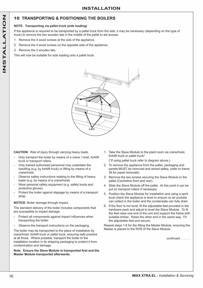
10 TRANSPORTING & POSITIONING THE BOILERS
CAUTION: Risk of injury through carrying heavy loads.
- Only transport the boiler by means of a crane / hoist, forklift truck or transport rollers.
- Only trained authorised personnel may undertake the handling (e.g. by forklift truck) or lifting by means of a crane/hoist.
- Observe safety instructions relating to the lifting of heavy loads (e.g. by means of a crane/hoist)
- Wear personal safety equipment (e.g. safety boots and protective gloves).
- Protect the boiler against slippage by means of a transport strap.
NOTICE: Boiler damage through impact.
The standard delivery of the boiler includes components that are susceptible to impact damage.
- Protect all components against impact influences when transporting the boiler.
- Observe the transport instructions on the packaging.
The boiler may be transported to the place of installation by crane/hoist, forklift truck or pallet truck, ensuring safe practice at all times. Where possible, transport the boiler to the installation location in its shipping packaging to protect it from contamination and damage.
Note. Ensure the Slave Module is transported first and the Master Module transported afterwards.
1. Take the Slave Module to the plant room via crane/hoist, forklift truck or pallet truck*.
(*If using pallet truck refer to diagram above.)2. To remove the appliance from the pallet, packaging and
panels MUST be removed and stored safely. (refer to frame 36 for panel removals)
3. Remove the two screws securing the Slave Module to the pallet (Centreline front and rear).
4. Slide the Slave Module off the pallet. At this point it can be put on transport rollers if necessary.
5. Position the Slave Module for installation and using a spirit level check the appliance is level to ensure no air pockets can collect in the boiler and the condensate can fully drain.
6. If the floor is not level, fit the adjustable feet provided in the hardware pack and adjust to level the Slave Module. To fit the feet raise one end of the unit and support the frame with suitable timber. Raise the other end in the same way. Fit the adjustable feet and secure.
Repeat steps 1-6 for the fitting the Master Module, ensuring the Master is placed to the RHS of the Slave Module.
continued . . . . . .
Lats
Woodscrews
NOTE. Transporting via pallet truck (side loading)If the appliance is required to be transported by a pallet truck from the side, it may be necessary (depending on the type of truck) to remove the two wooden lats in the middle of the pallet to aid access.
1. Remove the 4 wood screws at the side of the appliance.
2. Remove the 4 wood screws on the opposite side of the appliance.
3. Remove the 2 wooden lats.
This will now be suitable for side loading onto a pallet truck.
INS
TA
LL
AT
ION
17
INSTALLATION
IMAX XTRA EL - Installation & Servicing
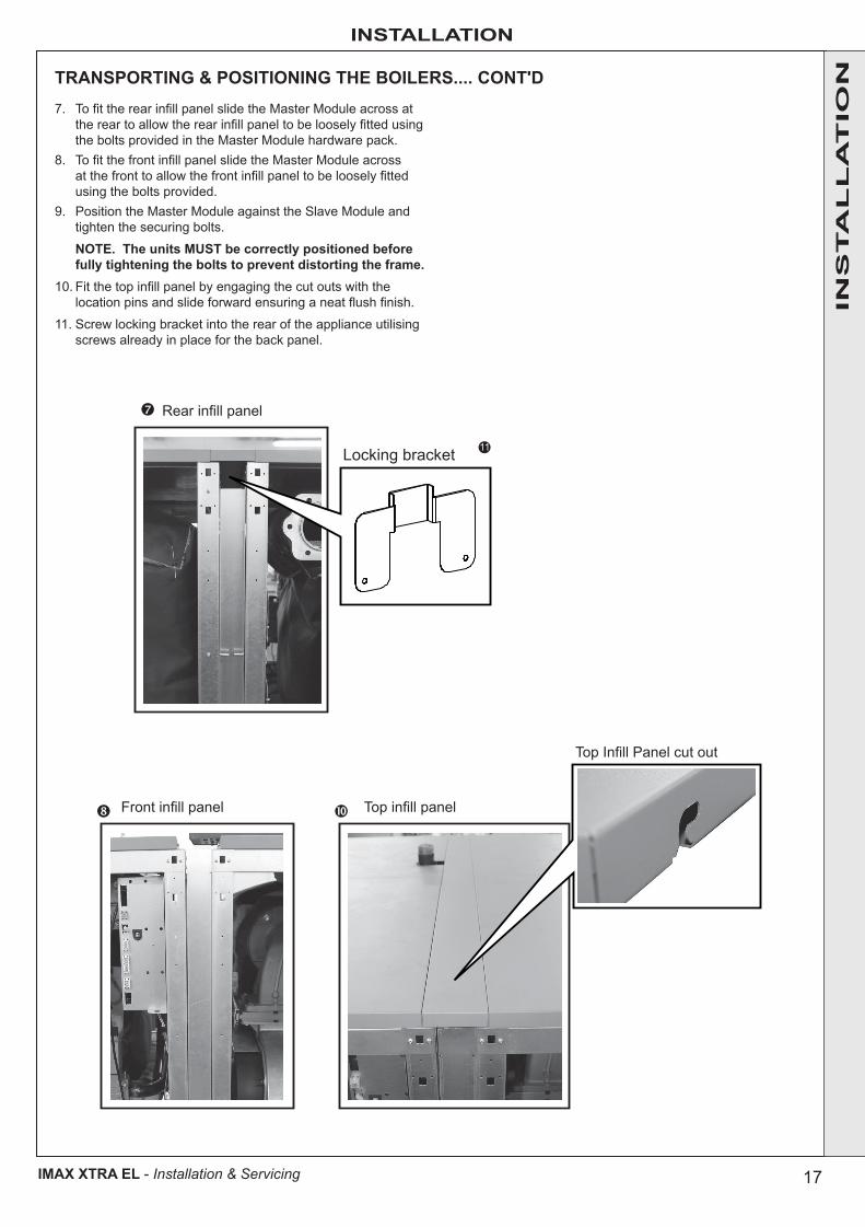
TRANSPORTING & POSITIONING THE BOILERS.... CONT'D
Top Infill Panel cut out
Locking bracket
Rear infill panel
Front infill panel Top infill panel
11
7. To fit the rear infill panel slide the Master Module across at the rear to allow the rear infill panel to be loosely fitted using the bolts provided in the Master Module hardware pack.
8. To fit the front infill panel slide the Master Module across at the front to allow the front infill panel to be loosely fitted using the bolts provided.
9. Position the Master Module against the Slave Module and tighten the securing bolts.
NOTE. The units MUST be correctly positioned before fully tightening the bolts to prevent distorting the frame.
10. Fit the top infill panel by engaging the cut outs with the location pins and slide forward ensuring a neat flush finish.
11. Screw locking bracket into the rear of the appliance utilising screws already in place for the back panel.
INS
TA
LL
AT
ION
18
INSTALLATION
IMAX XTRA EL - Installation & Servicing
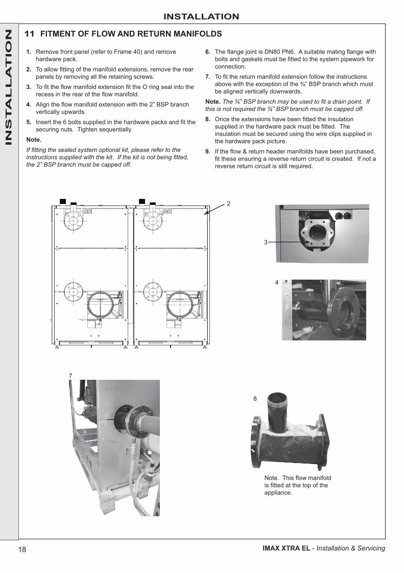
11 FITMENT OF FLOW AND RETURN MANIFOLDS
1. Remove front panel (refer to Frame 40) and remove hardware pack.
2. To allow fitting of the manifold extensions, remove the rear panels by removing all the retaining screws.
3. To fit the flow manifold extension fit the O ring seal into the recess in the rear of the flow manifold.
4. Align the flow manifold extension with the 2” BSP branch vertically upwards.
5. Insert the 6 bolts supplied in the hardware packs and fit the securing nuts. Tighten sequentially.
Note. If fitting the sealed system optional kit, please refer to the instructions supplied with the kit. If the kit is not being fitted, the 2” BSP branch must be capped off.
6. The flange joint is DN80 PN6. A suitable mating flange with bolts and gaskets must be fitted to the system pipework for connection.
7. To fit the return manifold extension follow the instructions above with the exception of the ¾” BSP branch which must be aligned vertically downwards.
Note. The ¾” BSP branch may be used to fit a drain point. If this is not required the ¾” BSP branch must be capped off.
8. Once the extensions have been fitted the insulation supplied in the hardware pack must be fitted. The insulation must be secured using the wire clips supplied in the hardware pack picture.
9. If the flow & return header manifolds have been purchased, fit these ensuring a reverse return circuit is created. If not a reverse return circuit is still required.
3
2
4
8
7
Note. This flow manifold is fitted at the top of the appliance.
INS
TA
LL
AT
ION
19
INSTALLATION
IMAX XTRA EL - Installation & Servicing
12 FLUE / AIR DUCT INSTALLATION1. FLUEWhen fitting the flue to the flue socket take care not to disturb the lip seal which must be present.
The flue should be supported using the bracket provided in such a way as not to place a load on the flue socket.
2. FITMENT OF THE FLUE ADAPTORTo fit the flue adaptor apply the lubricant provided with the flue adaptor in the hardware pack around the spigot or male end of the adaptor. Offer up the adaptor with the open drain point pointing vertically downwards and push the adaptor fully home into the socket.
3. FITMENT OF NON-RETURN VALVEThis stainless steel non-return valve must be fitted to the flue adaptor. The mains connector on the non return valve must be routed via the mains conduit then into the controls housing and fitted to the female connector as shown. The non return valve must be fitted with the motor housing to the outside of each of the modules.
4. FITMENT OF THE FLUE COMPONENTS(i) Remove the flue manifold and the two elbows from the
accessories pallet.
(ii) Locate two of the 250mm “V” flue clamps and the adhesive tube provided.
(iii) It is recommended to fit the elbows to the manifold before attempting to connect to the boiler non-return valves.
(iii) First ensure all components that require sealant are clean from any dirt, grease and other contaminants. This is extremely important to provide the correct surface conditions for the mastic sealant to adhere to. Failure to achieve this will result in an inadequate joint seal which will cause spillage.
(iv) Once decontamination has been achieved apply an adequate amount of sealant (ACC AS5600 ONLY) around the male locating spigot (please see illustration provided). This sealant location shown will guarantee that the connecting joints will be flue gas and moisture tight.
(v) Please note that removing the preformed seal and pumping mastic sealant into the groove formed within the female profile will not seal the connections correctly, the preformed seal should never be removed.
(vi) A silicone bead approximately 4mm in diameter applied around the joint circumference is considered to be the appropriate amount.
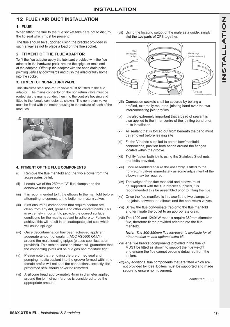
(vii) Using the locating spigot of the male as a guide, simply slot the two parts of CFS together.
(viii) Connection sockets shall be secured by bolting a profiled, externally mounted, jointing band over the two interconnecting joint profiles.
(ix) It is also extremely important that a bead of sealant is also applied to the inner centre of the jointing band prior to its installation.
(x) All sealant that is forced out from beneath the band must be removed before leaving site
(xi) Fit the V-bands supplied to both elbow/manifold connections, position both bands around the flanges located within the groove.
(xii) Tightly fasten both joints using the Stainless Steel nuts and bolts provided.
(xiii) Once assembled ensure the assembly is fitted to the non-return valves immediately as some adjustment of the elbows may be required.
(xiv) The weight of the flue manifold and elbows must be supported with the flue bracket supplied, it is recommended this be assembled prior to fitting the flue.
(xv) Once the flue manifold is in place fit the two clamps to the joints between the elbows and the non-return valves.
(xvi) Screw the flue condensate trap onto the flue manifold and terminate the outlet to an appropriate drain.
(xvii) The 1090 and 1240kW models require 350mm diameter flue, therefore fit the provided adapter into the flue manifold.
Note. The 300-350mm flue increaser is available for all other models as and optional extra kit.
(xviii) The flue bracket components provided in the flue kit MUST be fitted as shown to support the flue weight and ensure the flue cannot become detached from the boilers.
(xix)Any additional flue components that are fitted which are not provided by Ideal Boilers must be supported and made secure to ensure no movement.
continued . . . . .
INS
TA
LL
AT
ION
Maleconnection
spigotMale flange (sealant required)
V-band(sealant required)
SEALANT
SEALANT
20
INSTALLATION
IMAX XTRA EL - Installation & Servicing
INS
TA
LL
AT
ION
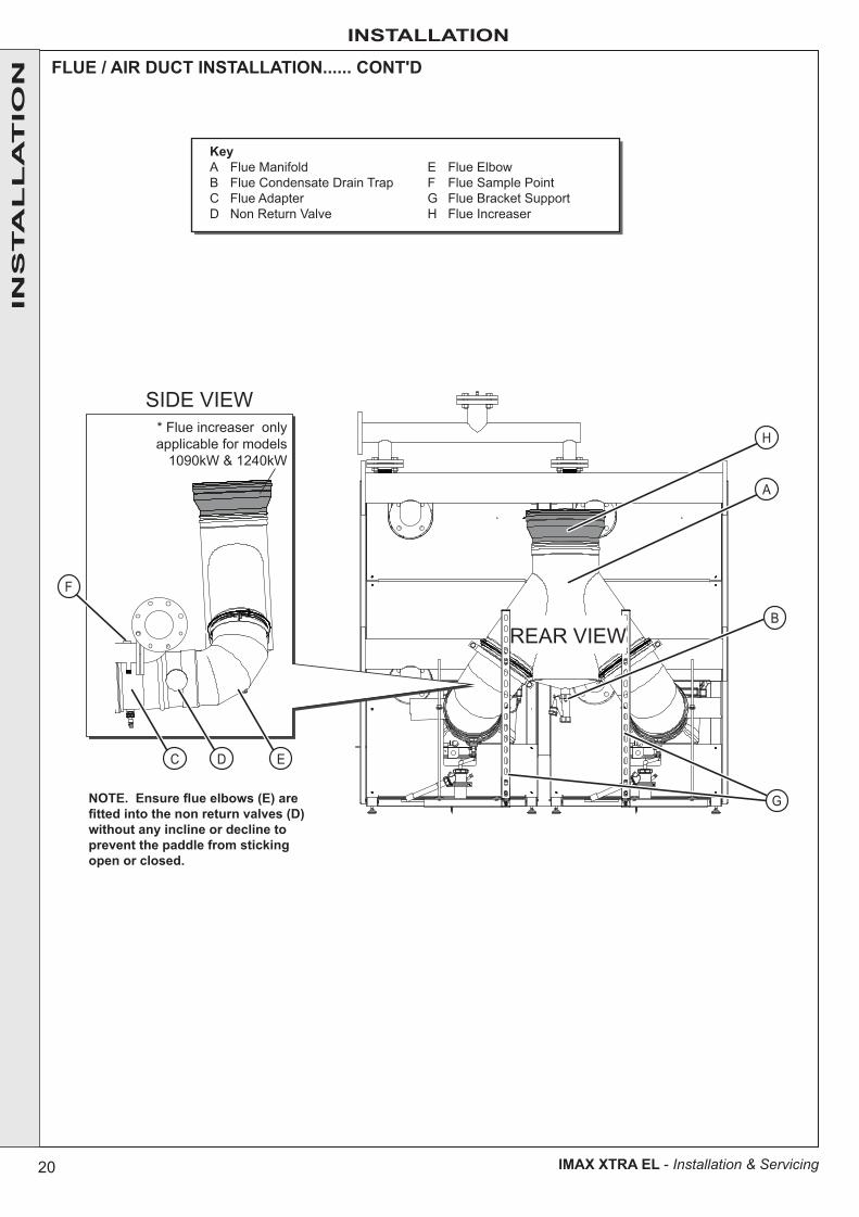
NOTE. Ensure flue elbows (E) are fitted into the non return valves (D) without any incline or decline to prevent the paddle from sticking open or closed.
KeyA Flue ManifoldB Flue Condensate Drain TrapC Flue AdapterD Non Return Valve
E Flue ElbowF Flue Sample PointG Flue Bracket SupportH Flue Increaser
A
H
B
C
F
D E
G
REAR VIEW
SIDE VIEW* Flue increaser onlyapplicable for models
1090kW & 1240kW
FLUE / AIR DUCT INSTALLATION...... CONT'D

21
INSTALLATION
IMAX XTRA EL - Installation & Servicing
FLUE / AIR DUCT INSTALLATION......CONT.
5. FITMENT OF FLUE BRACKETAssemble flue brackets for each module as shown below, ensuring the flue is supported and retained.
Once assembled fix the base of the bracket to the floor using appropriate screws. (not provided)
NOTE. Air DuctIf it is necessary to duct the air inlet from outside, the optional air duct kit must be purchased. Instructions for installation are provided with the kit.
INS
TA
LL
AT
ION
Flue Support / Retaining Bracket Arrangement
22
INSTALLATION
IMAX XTRA EL - Installation & Servicing
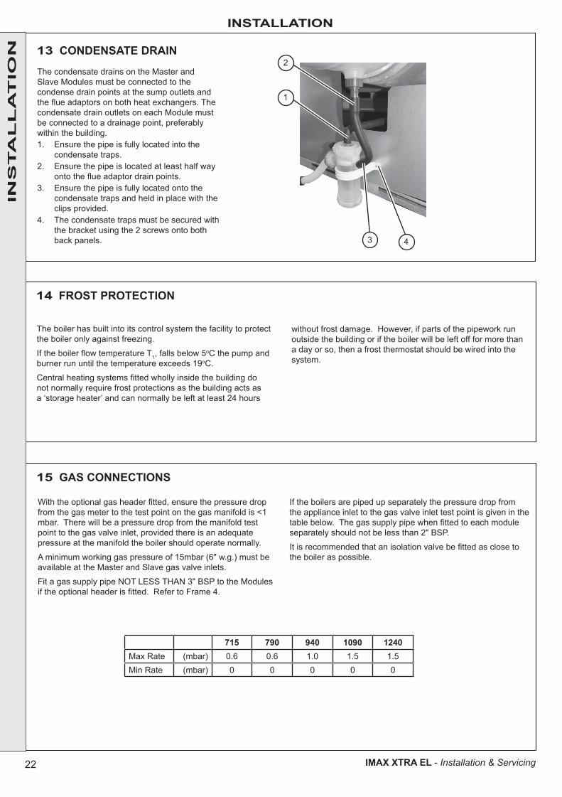
13 CONDENSATE DRAIN
The condensate drains on the Master and Slave Modules must be connected to the condense drain points at the sump outlets and the flue adaptors on both heat exchangers. The condensate drain outlets on each Module must be connected to a drainage point, preferably within the building.1. Ensure the pipe is fully located into the
condensate traps.2. Ensure the pipe is located at least half way
onto the flue adaptor drain points.3. Ensure the pipe is fully located onto the
condensate traps and held in place with the clips provided.
4. The condensate traps must be secured with the bracket using the 2 screws onto both back panels.
14 FROST PROTECTION
The boiler has built into its control system the facility to protect the boiler only against freezing.
If the boiler flow temperature T1, falls below 5oC the pump and burner run until the temperature exceeds 19oC.
Central heating systems fitted wholly inside the building do not normally require frost protections as the building acts as a ‘storage heater’ and can normally be left at least 24 hours
without frost damage. However, if parts of the pipework run outside the building or if the boiler will be left off for more than a day or so, then a frost thermostat should be wired into the system.
15 GAS CONNECTIONS
With the optional gas header fitted, ensure the pressure drop from the gas meter to the test point on the gas manifold is <1 mbar. There will be a pressure drop from the manifold test point to the gas valve inlet, provided there is an adequate pressure at the manifold the boiler should operate normally.
A minimum working gas pressure of 15mbar (6" w.g.) must be available at the Master and Slave gas valve inlets.
Fit a gas supply pipe NOT LESS THAN 3" BSP to the Modules if the optional header is fitted. Refer to Frame 4.
If the boilers are piped up separately the pressure drop from the appliance inlet to the gas valve inlet test point is given in the table below. The gas supply pipe when fitted to each module separately should not be less than 2" BSP.
It is recommended that an isolation valve be fitted as close to the boiler as possible.
715 790 940 1090 1240Max Rate (mbar) 0.6 0.6 1.0 1.5 1.5Min Rate (mbar) 0 0 0 0 0
3 4
1
2
INS
TA
LL
AT
ION
23
INSTALLATION
IMAX XTRA EL - Installation & Servicing
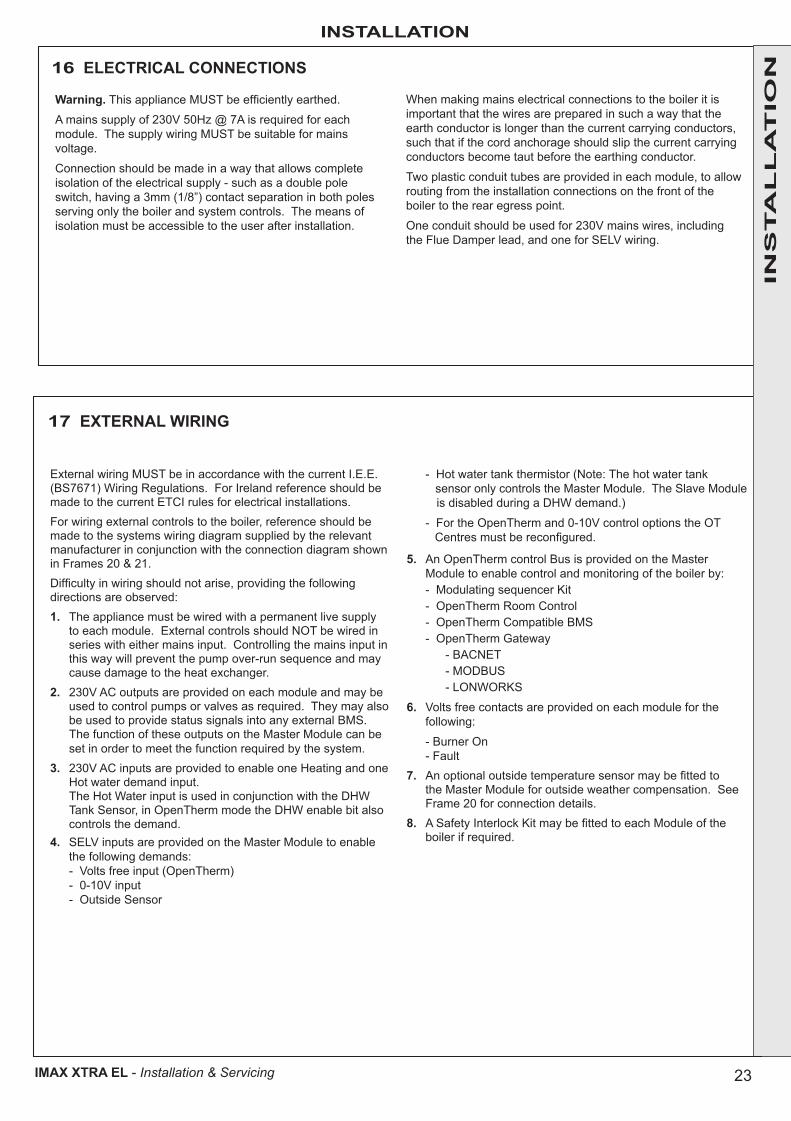
16 ELECTRICAL CONNECTIONS
Warning. This appliance MUST be efficiently earthed.
A mains supply of 230V 50Hz @ 7A is required for each module. The supply wiring MUST be suitable for mains voltage.
Connection should be made in a way that allows complete isolation of the electrical supply - such as a double pole switch, having a 3mm (1/8”) contact separation in both poles serving only the boiler and system controls. The means of isolation must be accessible to the user after installation.
When making mains electrical connections to the boiler it is important that the wires are prepared in such a way that the earth conductor is longer than the current carrying conductors, such that if the cord anchorage should slip the current carrying conductors become taut before the earthing conductor.
Two plastic conduit tubes are provided in each module, to allow routing from the installation connections on the front of the boiler to the rear egress point.
One conduit should be used for 230V mains wires, including the Flue Damper lead, and one for SELV wiring.
External wiring MUST be in accordance with the current I.E.E. (BS7671) Wiring Regulations. For Ireland reference should be made to the current ETCI rules for electrical installations.For wiring external controls to the boiler, reference should be made to the systems wiring diagram supplied by the relevant manufacturer in conjunction with the connection diagram shown in Frames 20 & 21.Difficulty in wiring should not arise, providing the following directions are observed:1. The appliance must be wired with a permanent live supply
to each module. External controls should NOT be wired in series with either mains input. Controlling the mains input in this way will prevent the pump over-run sequence and may cause damage to the heat exchanger.
2. 230V AC outputs are provided on each module and may be used to control pumps or valves as required. They may also be used to provide status signals into any external BMS. The function of these outputs on the Master Module can be set in order to meet the function required by the system.
3. 230V AC inputs are provided to enable one Heating and one Hot water demand input.
The Hot Water input is used in conjunction with the DHW Tank Sensor, in OpenTherm mode the DHW enable bit also controls the demand.
4. SELV inputs are provided on the Master Module to enable the following demands:
- Volts free input (OpenTherm) - 0-10V input - Outside Sensor
- Hot water tank thermistor (Note: The hot water tank sensor only controls the Master Module. The Slave Module is disabled during a DHW demand.)
- For the OpenTherm and 0-10V control options the OT Centres must be reconfigured.
5. An OpenTherm control Bus is provided on the Master Module to enable control and monitoring of the boiler by:
- Modulating sequencer Kit - OpenTherm Room Control - OpenTherm Compatible BMS - OpenTherm Gateway - BACNET - MODBUS - LONWORKS
6. Volts free contacts are provided on each module for the following:
- Burner On - Fault7. An optional outside temperature sensor may be fitted to
the Master Module for outside weather compensation. See Frame 20 for connection details.
8. A Safety Interlock Kit may be fitted to each Module of the boiler if required.
17 EXTERNAL WIRING
INS
TA
LL
AT
ION
24
INSTALLATION
IMAX XTRA EL - Installation & Servicing
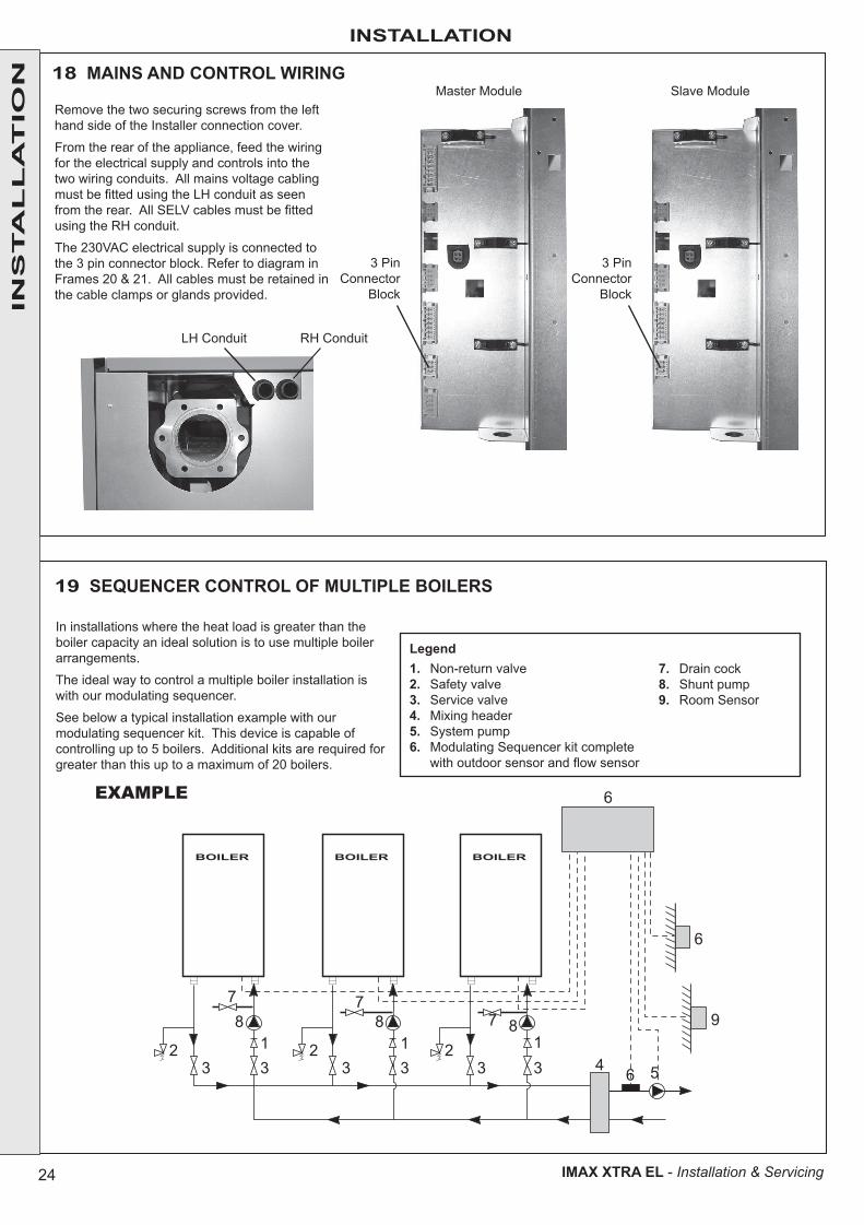
19 SEQUENCER CONTROL OF MULTIPLE BOILERS
In installations where the heat load is greater than the boiler capacity an ideal solution is to use multiple boiler arrangements.
The ideal way to control a multiple boiler installation is with our modulating sequencer.
See below a typical installation example with our modulating sequencer kit. This device is capable of controlling up to 5 boilers. Additional kits are required for greater than this up to a maximum of 20 boilers.
Legend1. Non-return valve2. Safety valve3. Service valve4. Mixing header5. System pump6. Modulating Sequencer kit complete
with outdoor sensor and flow sensor
7. Drain cock8. Shunt pump9. Room Sensor
3332
32 1
332 1
8 8 81
64
6
9
6
5
7 77
BOILER BOILERBOILER
EXAMPLE
18 MAINS AND CONTROL WIRING
Remove the two securing screws from the left hand side of the Installer connection cover.
From the rear of the appliance, feed the wiring for the electrical supply and controls into the two wiring conduits. All mains voltage cabling must be fitted using the LH conduit as seen from the rear. All SELV cables must be fitted using the RH conduit.
The 230VAC electrical supply is connected to the 3 pin connector block. Refer to diagram in Frames 20 & 21. All cables must be retained in the cable clamps or glands provided.
LH Conduit
3 PinConnector
Block
3 PinConnector
Block
RH Conduit
Master Module Slave Module
INS
TA
LL
AT
ION
25
INSTALLATION
IMAX XTRA EL - Installation & Servicing
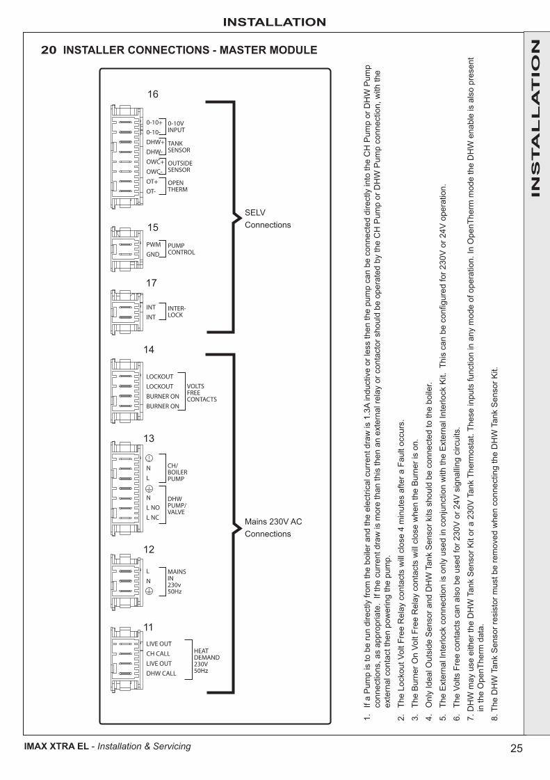
20 INSTALLER CONNECTIONS - MASTER MODULE
1.
If a
Pum
p is
to b
e ru
n di
rect
ly fr
om th
e bo
iler a
nd th
e el
ectri
cal c
urre
nt d
raw
is 1
.3A
indu
ctiv
e or
less
then
the
pum
p ca
n be
con
nect
ed d
irect
ly in
to th
e C
H P
ump
or D
HW
Pum
p co
nnec
tions
, as
appr
opria
te.
If th
e cu
rren
t dra
w is
mor
e th
an th
is th
en a
n ex
tern
al re
lay
or c
onta
ctor
sho
uld
be o
pera
ted
by th
e C
H P
ump
or D
HW
Pum
p co
nnec
tion,
with
the
exte
rnal
con
tact
then
pow
erin
g th
e pu
mp.
2.
The
Lock
out V
olt F
ree
Rel
ay c
onta
cts
will
clo
se 4
min
utes
afte
r a F
ault
occu
rs.
3.
The
Bur
ner O
n Vo
lt Fr
ee R
elay
con
tact
s w
ill c
lose
whe
n th
e B
urne
r is
on.
4.
Onl
y Id
eal O
utsi
de S
enso
r and
DH
W T
ank
Sen
sor k
its s
houl
d be
con
nect
ed to
the
boile
r.
5.
The
Ext
erna
l Int
erlo
ck c
onne
ctio
n is
onl
y us
ed in
con
junc
tion
with
the
Ext
erna
l Int
erlo
ck K
it. T
his
can
be c
onfig
ured
for 2
30V
or 2
4V o
pera
tion.
6.
The
Volts
Fre
e co
ntac
ts c
an a
lso
be u
sed
for 2
30V
or 2
4V s
igna
lling
circ
uits
.
7. D
HW
may
use
eith
er th
e D
HW
Tan
k S
enso
r Kit
or a
230
V T
ank
Ther
mos
tat.
Thes
e in
puts
func
tion
in a
ny m
ode
of o
pera
tion.
In O
penT
herm
mod
e th
e D
HW
ena
ble
is a
lso
pres
ent
in
the
Ope
nThe
rm d
ata.
8. T
he D
HW
Tan
k S
enso
r res
isto
r mus
t be
rem
oved
whe
n co
nnec
ting
the
DH
W T
ank
Sen
sor K
it.
0-10+0-10-DHW+DHW-OWC+OWC-OT+OT-
0-10VINPUT
PWMGND
PUMPCONTROL
INTINT
INTER-LOCK
LOCKOUTLOCKOUTBURNER ONBURNER ON
VOLTSFREECONTACTS
NL
NL NOL NC
CH/BOILERPUMP
DHWPUMP/VALVE
LN
MAINSIN230v50Hz
LIVE OUTCH CALLLIVE OUTDHW CALL
HEATDEMAND230V50Hz
TANKSENSOR
OUTSIDESENSOR
OPENTHERM
SELVConnections
Mains 230V ACConnections
INS
TA
LL
AT
ION
16
15
17
14
13
12
11
26
INSTALLATION
IMAX XTRA EL - Installation & Servicing
INS
TA
LL
AT
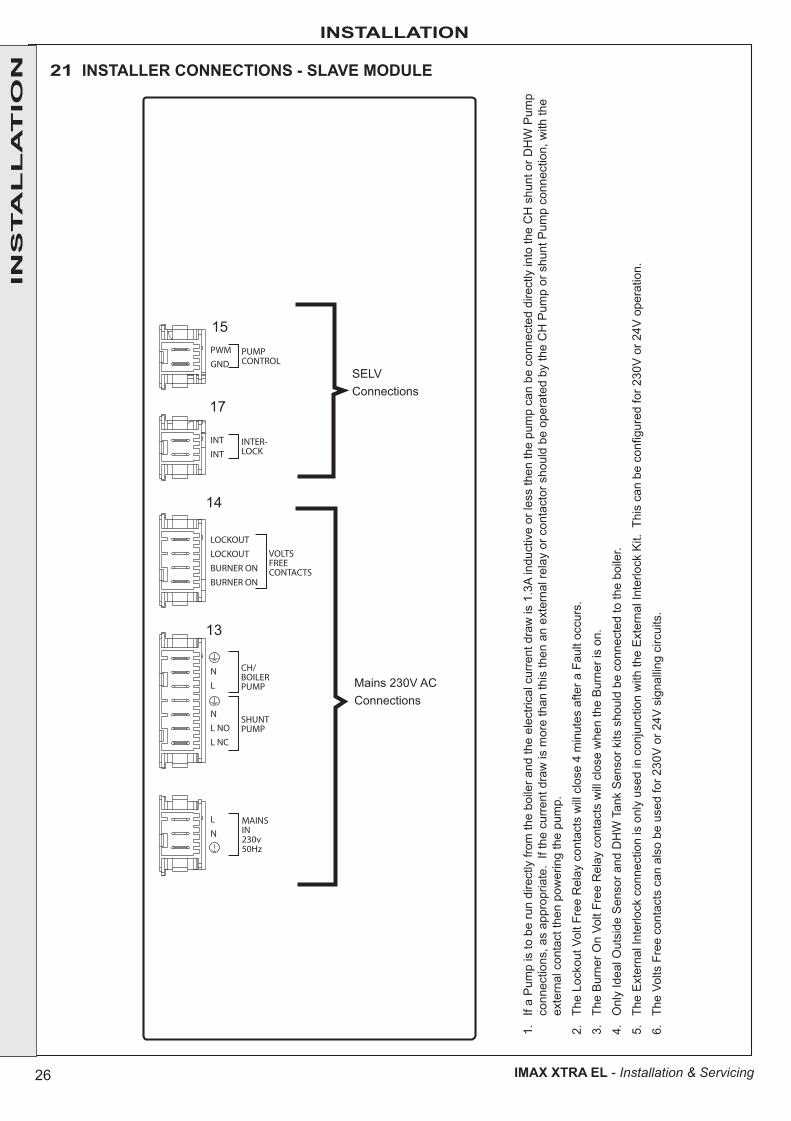
ION 21 INSTALLER CONNECTIONS - SLAVE MODULE
1.
If a
Pum
p is
to b
e ru
n di
rect
ly fr
om th
e bo
iler a
nd th
e el
ectri
cal c
urre
nt d
raw
is 1
.3A
indu
ctiv
e or
less
then
the
pum
p ca
n be
con
nect
ed d
irect
ly in
to th
e C
H s
hunt
or D
HW
Pum
p co
nnec
tions
, as
appr
opria
te.
If th
e cu
rren
t dra
w is
mor
e th
an th
is th
en a
n ex
tern
al re
lay
or c
onta
ctor
sho
uld
be o
pera
ted
by th
e C
H P
ump
or s
hunt
Pum
p co
nnec
tion,
with
the
exte
rnal
con
tact
then
pow
erin
g th
e pu
mp.
2.
The
Lock
out V
olt F
ree
Rel
ay c
onta
cts
will
clo
se 4
min
utes
afte
r a F
ault
occu
rs.
3.
The
Bur
ner O
n Vo
lt Fr
ee R
elay
con
tact
s w
ill c
lose
whe
n th
e B
urne
r is
on.
4.
Onl
y Id
eal O
utsi
de S
enso
r and
DH
W T
ank
Sen
sor k
its s
houl
d be
con
nect
ed to
the
boile
r.
5.
The
Ext
erna
l Int
erlo
ck c
onne
ctio
n is
onl
y us
ed in
con
junc
tion
with
the
Ext
erna
l Int
erlo
ck K
it. T
his
can
be c
onfig
ured
for 2
30V
or 2
4V o
pera
tion.
6.
The
Volts
Fre
e co
ntac
ts c
an a
lso
be u
sed
for 2
30V
or 2
4V s
igna
lling
circ
uits
.
PWMGND
PUMPCONTROL
INTINT
INTER-LOCK
LOCKOUTLOCKOUTBURNER ONBURNER ON
VOLTSFREECONTACTS
NL
NL NOL NC
CH/BOILERPUMP
LN
SHUNTPUMP
MAINSIN230v50Hz
SELVConnections
Mains 230V ACConnections
15
17
14
13

27
INSTALLATION
IMAX XTRA EL - Installation & Servicing
S1
S2
Rear of OT Center
INS
TA
LL
AT
ION
23 FITTING OT CENTER
22 OT CENTER CONFIGURATION
The OT Centers on each module are factory pre-set as master and Slave Modules for CH ON/OFF call for heat.
To check the settings or to configure for alternative control options remove the OT Center and set switches "S1 and "S2" according to the tables below (See Frame 52 for details of how to remove and replace OT Centers).
Position S2 Function
1 Master - Module
2 Slave Module
Position S1 Function
1 N/A
2 N/A
3 Opentherm programmable room stat or sequencer kit
4 CH ON-OFF call for heat
5 0 to 10 V Input
Note.Both OT Centers (Master and Slave Modules) must be configured similarly.
1. Locate the communication lead attached to the OT Center on the Master Module.
2. Plug in the RJ11 connector, then route the cable around the internal surface of the Controls enclosure locating it in each clip as shown.
3. Route the cable through the hole where the User Interface lead exits the Controls enclosure.
4. Clip the cable into the locating points across the inner panel at the front of the boiler, as shown.
5. Once you reach the Slave Module, once again route the cable around the internal surface of the Controls enclosure locating it in each clip as shown.
6. Plug remaining end into either socket on Slave Module OT Center.
3
4
5
3
MASTER MODULESLAVE MODULE 2
28
INSTALLATION
IMAX XTRA EL - Installation & Servicing
CU
I GN
D4
CU
I +7.
5/12
V3
CU
I EB
US
+2
CU
I MO
DE
1
CU
I
KM
721-
I4
OT
Cen
tre
Ope
nThe
rm
0-10
V
12
34
1110
98
76
54
32
16
54
32
16
54
32
12
14
32
13
21
54
32
14
32
14
32
13
21
32
12
1
A1
B1
APS
```
DP
FLO
WIG
N3
21
FGPS
DIA
GN
OS
TIC
S1
I6I5
WPS
12
34
56
78
12
FSI3
12
34
56
7
IL 1
I4
S2
12
34
IL 2
HX
FC1
23
45
GV
To C
hass
is P
E1 2
Not
e: 0
.75m
msq
I13
Blu
e an
d br
own
from
I2
FPI2
12
34
12
3
GVE
LN
PE
`
From
OT
Cen
tre
SU
PP
LY
EM
C F
ilter
L
CH
ToO
T C
entre
ToO
T C
entre
NL
NO
NL
NO
BO
ILE
R/C
H P
UM
PD
HW
DIV
ER
TER
/PU
MP
DH
W
FAU
LTR
UN
DH
WO
utsi
deS
enso
rO
penT
herm
Pum
p P
WM
RLA
/1
DHW/CH2 SWITCHED LIVE
PR2
PR2
FAN-PE
FAN-N
OWC-NTC+
OWC-NTC-
OPENTHERM-
OPENTHERM+
PUMP PWMGND
X1C
X1B
PUMP-L
From
OT
Cen
tre
From
Inst
alle
r con
nect
ions
RLB
/1
OT
Sla
ve
10
NO
3 Run
To In
stal
ler C
onne
ctio
nsC3
NO
4C
4N
C4
1917
OT
Mas
ter
0-10
V0V
C1
NO
1
2C
2O
NM
89
8161
5141
3121
11
23
45
67
X1A
D1X
A2X
B2X
3X
CUI EBUS +CUI MODE
X10
SE
LV
SE
LVV
OLT
S F
RE
E23
0V A
C
To K
M7
Faul
t
1
DI1
DI2
CH SWITCHED LIVE
GA
SV
ALV
E
AIR
PR
ES
SU
RE
SW
ITC
H1
2 43
IGN
ITIO
NE
LEC
TRO
DE
FAN
2 1
H/X
DE
TEC
TIO
NE
LEC
TRO
DE
RE
TUR
N
SP
AR
KG
EN
ER
ATO
R
RET
FLU
E G
AS
PR
ES
SU
RE
SW
ITC
H
FLO
W 21
0-10
V
MAINS SUPPLY-PE
MAINS SUPPLY-N
MAINS SUPPLY-L
DIVERER VALVE-L CH
DIVERER VALVE-L DHW
GAS VALVE-PE
GAS VALVE-N
PUMP-PE
PUMP-N
GAS VALVE-L
GAS VALVE-N
DIVERER VALVE-PE
DIVERER VALVE-N
IONISATION
IGNITION-PE
IGNITION-N
IGNITION-L
PR3
PR3
DHW-NTC+DHW-NTC-
EBUS +
EBUS - (GND)
CUI GNDCUI +7.5/12V
6X
8X
0-10V +NCWPS +WPS -0-10V -NCFAN-SPEED
X13
X4
X7C
X7B
X7A
RETURN-NTC+RETURN-NTC-
PE
L N
C
SW
LL
SW
L
WA
TER
PR
ES
SU
RE
SW
ITC
H
PE
43
21
Dam
per
Con
nect
or
PWN-FAN+VEPWM-FAN-VEFLUE-NTC+FLUE-NTC-
FLOW-NTC+FLOW-NTC-
FAN-L
IONISATION-PE
TTL
C
onne
ctio
n to
Sla
ve
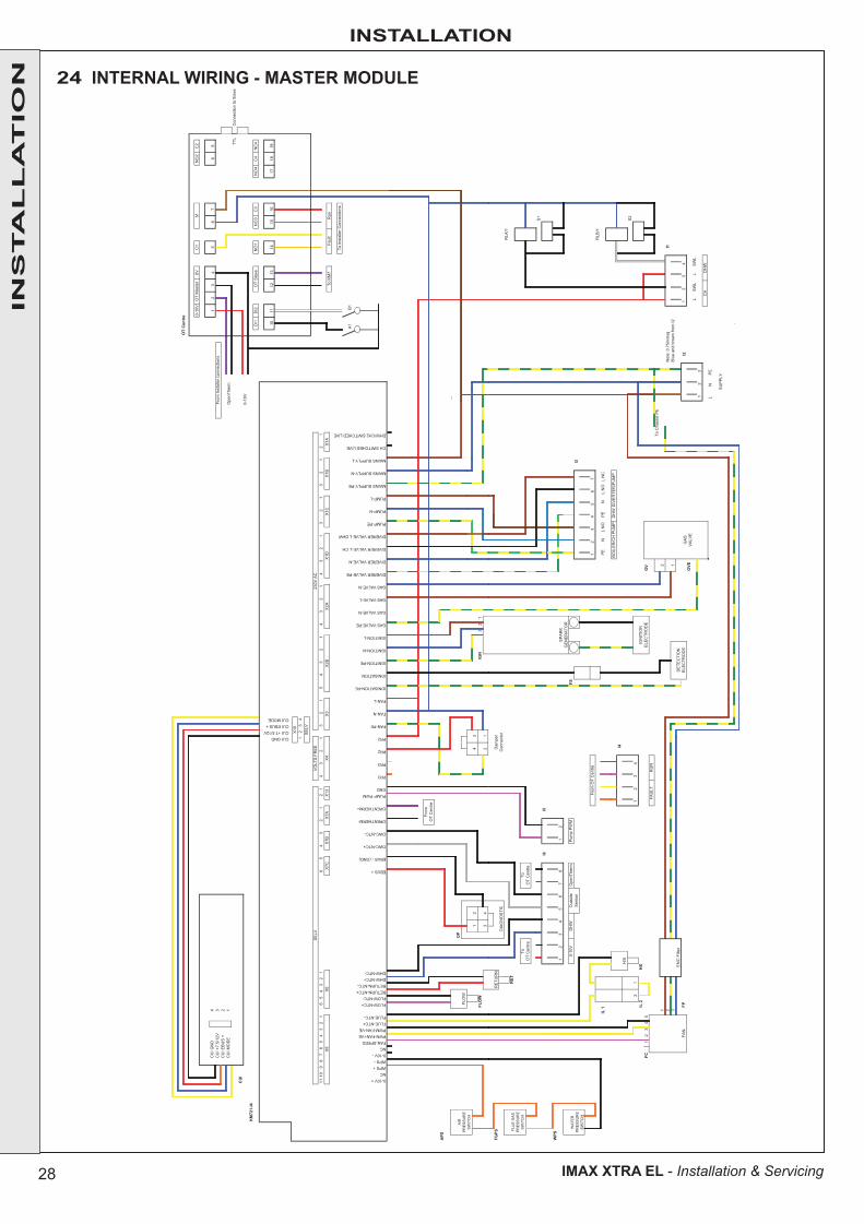
24 INTERNAL WIRING - MASTER MODULE
INS
TA
LL
AT
ION

29
INSTALLATION
IMAX XTRA EL - Installation & Servicing
CU
I GN
D4
CU
I +7.
5/12
V3
CU
I EB
US
+2
CU
I MO
DE
1
CU
IK
M72
1-I4
OT
Cen
tre
12
34
1110
98
76
54
32
16
54
32
16
54
32
12
14
32
13
21
54
32
14
32
14
32
13
21
32
12
1
APS
DP
FLO
WIG
N
FGPS
DIA
GN
OS
TIC
``
I5
WPS
12
FSI3
12
34
56
7
IL 1
I4
12
34
IL 2
HX
FC1
23
45
GV
To C
hass
is P
E1 2
Not
e: 0
.75m
msq
3B
lue
and
brow
n fro
m I2
FPI2
12
3
GVE
LN
PE
`
RE
TUR
N
PE
From
OT
Cen
tre
From
OT
Cen
tre
Pum
p P
WM
NL
NO
BO
ILE
R/C
H P
UM
P
H/X
IGN
ITIO
NE
LEC
TRO
DE
34
FLU
E G
AS
PR
ES
SU
RE
SW
ITC
H
21
SP
AR
KG
EN
ER
ATO
R
Dam
per
Con
nect
or
WA
TER
PR
ES
SU
RE
SW
ITC
H
RET
GAS VALVE-N
FAN-PE
FAN-N
FAN-L
OWC-NTC-
OPENTHERM-
OPENTHERM+
PUMP PWMGND
PR3
0-10V +NCWPS +WPS -0-10V -NC
GAS VALVE-L
GAS VALVE-N
DIVERER VALVE-PE
DIVERER VALVE-N
DIVERER VALVE-L CH
IONISATION-PE
IONISATION
IGNITION-PE
IGNITION-N
IGNITION-L
GAS VALVE-PE
MAINS SUPPLY-L
CH SWITCHED LIVE
DHW/CH2 SWITCHED LIVE
DIVERER VALVE-L DHW
PUMP-PE
PUMP-N
PUMP-L
MAINS SUPPLY-PE
MAINS SUPPLY-N
FAN-SPEEDPWN-FAN+VE
X4
RETURN-NTC-DHW-NTC+DHW-NTC-
EBUS +
EBUS - (GND)
OWC-NTC+
PWM-FAN-VEFLUE-NTC+FLUE-NTC-
FLOW-NTC+FLOW-NTC-RETURN-NTC+
PR3
PR2
PR2
VO
LTS
FR
EE
230V
AC
31X
A7X
B7X
C7X
6X
8X
X1B
X1A
C1X
D1X
A2X
B2X
3X
CUI GNDCUI +7.5/12VCUI EBUS +CUI MODE
X10
2C
2O
NM
1C
V0retsa
M TO
V01-0
98
76
54
32
1
DI1
DI2
OT
Sla
veN
O1
NO
3C
3N
O4
C4
NC
4
19
To K
M7
Faul
tR
un
To In
stal
ler C
onne
ctio
ns
AIR
PR
ES
SU
RE
SW
ITC
HFL
OW
12
43
1011
1213
1415
1617
18
SE
LV
SE
LV
SU
PP
LY
PE
L N
CN
L N
O
DH
W D
IVE
RTE
R/P
UM
P
GA
SV
ALV
E
FAN
2 1D
ETE
CTI
ON
ELE
CTR
OD
E
21
TTL
C
onne
ctio
n to
Mas
ter
25 INTERNAL WIRING - SLAVE MODULE
INS
TA
LL
AT
ION
30
INSTALLATION
IMAX XTRA EL - Installation & Servicing
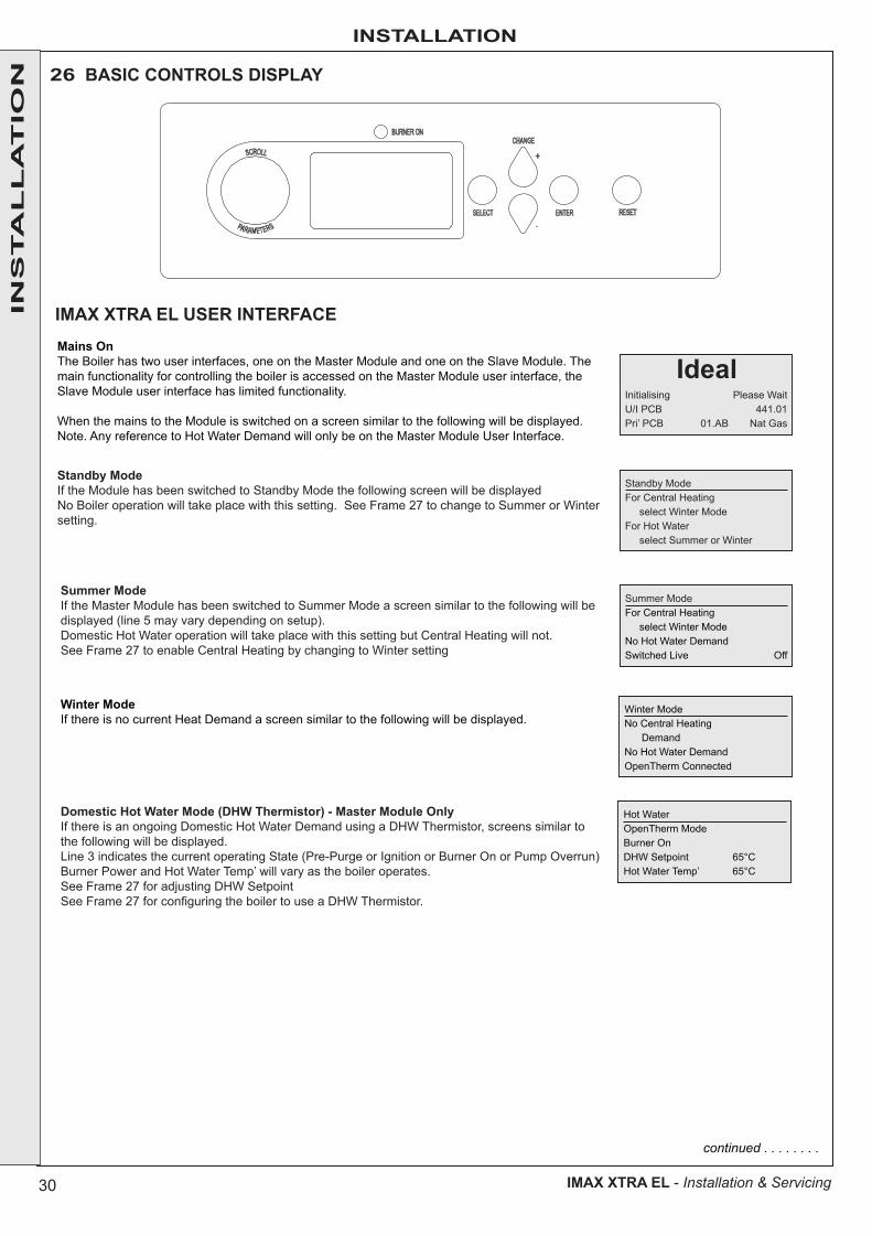
26 BASIC CONTROLS DISPLAY
Mains OnThe Boiler has two user interfaces, one on the Master Module and one on the Slave Module. The main functionality for controlling the boiler is accessed on the Master Module user interface, the Slave Module user interface has limited functionality.
When the mains to the Module is switched on a screen similar to the following will be displayed. Note. Any reference to Hot Water Demand will only be on the Master Module User Interface.
Initialising Please WaitU/I PCB 441.01Pri’ PCB 01.AB Nat Gas
Standby ModeFor Central Heating select Winter ModeFor Hot Water select Summer or Winter
Ideal
Standby ModeIf the Module has been switched to Standby Mode the following screen will be displayedNo Boiler operation will take place with this setting. See Frame 27 to change to Summer or Winter setting.
Summer ModeFor Central Heating select Winter ModeNo Hot Water DemandSwitched Live Off
Summer ModeIf the Master Module has been switched to Summer Mode a screen similar to the following will be displayed (line 5 may vary depending on setup).Domestic Hot Water operation will take place with this setting but Central Heating will not.See Frame 27 to enable Central Heating by changing to Winter setting
IMAX XTRA EL USER INTERFACE
continued . . . . . . . .
Winter ModeNo Central Heating DemandNo Hot Water DemandOpenTherm Connected
Winter ModeIf there is no current Heat Demand a screen similar to the following will be displayed.
Hot WaterOpenTherm ModeBurner OnDHW Setpoint 65°CHot Water Temp’ 65°C
Domestic Hot Water Mode (DHW Thermistor) - Master Module OnlyIf there is an ongoing Domestic Hot Water Demand using a DHW Thermistor, screens similar to the following will be displayed.Line 3 indicates the current operating State (Pre-Purge or Ignition or Burner On or Pump Overrun)Burner Power and Hot Water Temp’ will vary as the boiler operates.See Frame 27 for adjusting DHW SetpointSee Frame 27 for configuring the boiler to use a DHW Thermistor.
BURNER ONCHANGE
RESETSELECT ENTER-
+SCROLL
PARAMETERS
INS
TA
LL
AT
ION
31
INSTALLATION
IMAX XTRA EL - Installation & Servicing
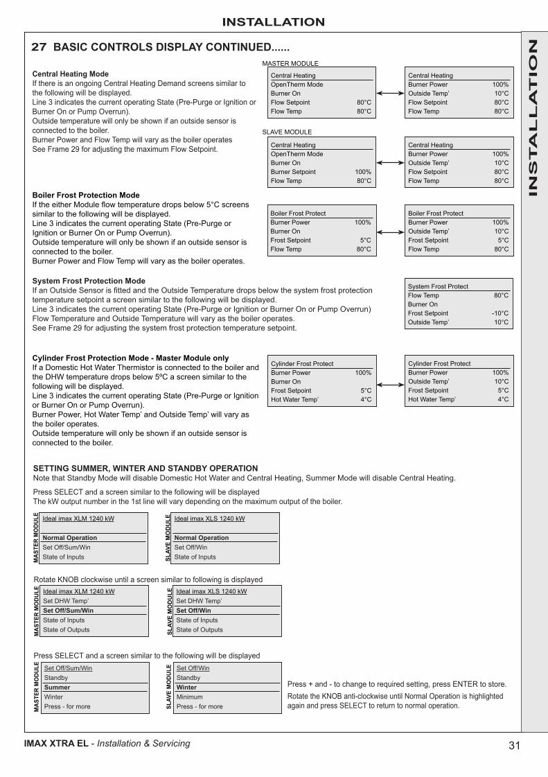
27 BASIC CONTROLS DISPLAY CONTINUED......
Central HeatingOpenTherm ModeBurner OnFlow Setpoint 80°CFlow Temp 80°C
MASTER MODULE
SLAVE MODULE
Central HeatingOpenTherm ModeBurner OnBurner Setpoint 100%Flow Temp 80°C
Central Heating ModeIf there is an ongoing Central Heating Demand screens similar to the following will be displayed.Line 3 indicates the current operating State (Pre-Purge or Ignition or Burner On or Pump Overrun).Outside temperature will only be shown if an outside sensor is connected to the boiler.Burner Power and Flow Temp will vary as the boiler operatesSee Frame 29 for adjusting the maximum Flow Setpoint.
Central HeatingBurner Power 100%Outside Temp’ 10°CFlow Setpoint 80°CFlow Temp 80°C
Central HeatingBurner Power 100%Outside Temp’ 10°CFlow Setpoint 80°CFlow Temp 80°C
Boiler Frost Protection ModeIf the either Module flow temperature drops below 5°C screens similar to the following will be displayed.Line 3 indicates the current operating State (Pre-Purge or Ignition or Burner On or Pump Overrun).Outside temperature will only be shown if an outside sensor is connected to the boiler.Burner Power and Flow Temp will vary as the boiler operates.
Boiler Frost ProtectBurner Power 100%Outside Temp’ 10°CFrost Setpoint 5°CFlow Temp 80°C
Boiler Frost ProtectBurner Power 100%Burner OnFrost Setpoint 5°CFlow Temp 80°C
System Frost ProtectFlow Temp 80°CBurner OnFrost Setpoint -10°COutside Temp’ 10°C
System Frost Protection ModeIf an Outside Sensor is fitted and the Outside Temperature drops below the system frost protection temperature setpoint a screen similar to the following will be displayed.Line 3 indicates the current operating State (Pre-Purge or Ignition or Burner On or Pump Overrun)Flow Temperature and Outside Temperature will vary as the boiler operates.See Frame 29 for adjusting the system frost protection temperature setpoint.
Cylinder Frost ProtectBurner Power 100%Outside Temp’ 10°CFrost Setpoint 5°CHot Water Temp’ 4°C
Cylinder Frost Protection Mode - Master Module onlyIf a Domestic Hot Water Thermistor is connected to the boiler and the DHW temperature drops below 5ºC a screen similar to the following will be displayed.Line 3 indicates the current operating State (Pre-Purge or Ignition or Burner On or Pump Overrun).Burner Power, Hot Water Temp’ and Outside Temp’ will vary as the boiler operates.Outside temperature will only be shown if an outside sensor is connected to the boiler.
Cylinder Frost ProtectBurner Power 100%Burner OnFrost Setpoint 5°CHot Water Temp’ 4°C
Master Module display: See specification, 3.2.10
Slave Module display: See specification 3.2.9
Ideal imax XLM 1240 kW
Normal OperationSet Off/Sum/WinState of Inputs
Ideal imax XLS 1240 kW
Normal OperationSet Off/WinState of Inputs
Press SELECT and a screen similar to the following will be displayedThe kW output number in the 1st line will vary depending on the maximum output of the boiler.
Ideal imax XLM 1240 kWSet DHW Temp’Set Off/Sum/WinState of InputsState of Outputs
Ideal imax XLS 1240 kWSet DHW Temp’Set Off/WinState of InputsState of Outputs
Rotate KNOB clockwise until a screen similar to following is displayed
Set Off/Sum/WinStandbySummerWinterPress - for more
Set Off/WinStandbyWinterMinimumPress - for more
Press SELECT and a screen similar to the following will be displayed
Press + and - to change to required setting, press ENTER to store.Rotate the KNOB anti-clockwise until Normal Operation is highlighted again and press SELECT to return to normal operation.
SETTING SUMMER, WINTER AND STANDBY OPERATIONNote that Standby Mode will disable Domestic Hot Water and Central Heating, Summer Mode will disable Central Heating.
SLAV
E M
OD
ULE
SLAV
E M
OD
ULE
MAS
TER
MO
DULE
MAS
TER
MO
DULE
SLAV
E M
ODU
LE
MAS
TER
MO
DULE
INS
TA
LL
AT
ION

32
INSTALLATION
IMAX XTRA EL - Installation & Servicing
28 IMAX XTRA EL USER INTERFACE - BASIC OPERATING INSTRUCTIONS CONTINUED...
continued . . . . . . . .
VIEWING THE STATE OF THE MODULE INPUTS
Press SELECT and a screen similar to the following will be displayedThe kW output number in the 1st line will vary depending on the maximum output of the boiler.
Ideal imax XLM 1240 kWSet Off/Sum/WinState of InputsState of OutputsFault History
Ideal imax XLM 1240 kWState of InputsState of OutputsFault HistoryShow Hours Run
Ideal imax XLS 1240 kWSet Off/WinState of InputsState of OutputsFault History
Ideal imax XLS 1240 kWState of InputsState of OutputsFault HistoryShow Hours Run
Rotate KNOB clockwise until a screen similar to the following is displayed
State of InputsFlow Temp’ 80ºCReturn Temp’ 60ºCHX Temperature 70ºCPress - for more
Press SELECT and a screen similar to the following will be displayed
The state of the iniputs will vary as the boiler operates.Press SELECT to exit this option.Rotate the KNOB anti-clockwise until Normal Operation is highlighted again and press SELECT to return to normal operation.
Press SELECT and a screen similar to the following will be displayedThe kW output number in the 1st line will vary depending on the maximum output of the boiler.
Rotate KNOB clockwise until a screen similar to the following is displayed.
VIEWING THE STATE OF THE BOILER OUTPUTS
Press SELECT and a screen similar to the following will be displayed.
State of OutputsBoiler Pump OnDHW Pump/Valve OffFan 3000rpmPress - for more
State of OutputsBoiler Pump OnShunt Pump OffFan 3000rpmPress - for more
The state of the outputs will vary as the boiler operates.Press SELECT to exit this option.Rotate the KNOB anti-clockwise until Normal Operation is highlighted again and press SELECT to return to normal operation.
VIEWING THE FAULT HISTORY OF THE MODULE
Press SELECT and a screen similar to the following will be displayedThe kW output number in the 1st line will vary depending on the maximum output of the boiler.
Rotate KNOB clockwise until a screen similar to the following is displayed
Ideal imax XLM 1240 kWState of OutputsFault HistoryShow Hours RunNormal Operation
Ideal imax XLS 1240 kWState of OutputsFault HistoryShow Hours RunNormal Operation
Press SELECT and a screen similar to the following will be displayed
Fault History: Max 10Fault 1 [Latest]Ignition Lockout [16]23 days agoPress - for more
The Fault History will vary depending on the operation of the boiler.Press SELECT to exit this option.Rotate the KNOB anti-clockwise until Normal Operation is highlighted again and press SELECT to return to normal operation.
VIEWING THE BOILER HOURS RUN
Press SELECT and a screen similar to the following will be displayedThe kW output number in the 1st line will vary depending on the maximum output of the boiler.
Rotate KNOB clockwise until a screen similar to following is displayed.Ideal imax XLM 1240 kWFault HistoryShow Hours RunNormal Operation
Ideal imax XLS 1240 kWFault HistoryShow Hours RunNormal Operation
Press SELECT and a screen similar to the following will be displayed.Show Hours Run Total Hours 20 hFlame On 10 h
The times will vary depending on the operation of the boiler.Press SELECT to exit this option.Rotate the KNOB anti-clockwise until Normal Operation is highlighted again and press SELECT to return to normal operation.
Ideal imax XLM 1240 kW
Normal OperationSet Off/Sum/WinState of Inputs
Ideal imax XLM 1240 kW
Normal OperationSet Off/Sum/WinState of Inputs
Ideal imax XLM 1240 kW
Normal OperationSet Off/Sum/WinState of Inputs
Ideal imax XLM 1240 kW
Normal OperationSet Off/Sum/WinState of Inputs
Ideal imax XLS 1240 kW
Normal OperationSet Off/WinState of Inputs
Ideal imax XLS 1240 kW
Normal OperationSet Off/WinState of Inputs
Ideal imax XLS 1240 kW
Normal OperationSet Off/WinState of Inputs
Ideal imax XLS 1240 kW
Normal OperationSet Off/WinState of Inputs
SLAV
E M
OD
ULE
SLAV
E M
OD
ULE
SLAV
E M
OD
ULE
SLAV
E M
OD
ULE
SLAV
E M
OD
ULE
SLAV
E M
OD
ULE
SLAV
E M
OD
ULE
SLAV
E M
OD
ULE
SLAV
E M
OD
ULE
MAS
TER
MO
DULE
MAS
TER
MO
DULE
MAS
TER
MO
DULE
MAS
TER
MO
DULE
MAS
TER
MO
DULE
MAS
TER
MO
DULE
MAS
TER
MO
DULE
MAS
TER
MO
DULE
MAS
TER
MO
DULE
INS
TA
LL
AT
ION
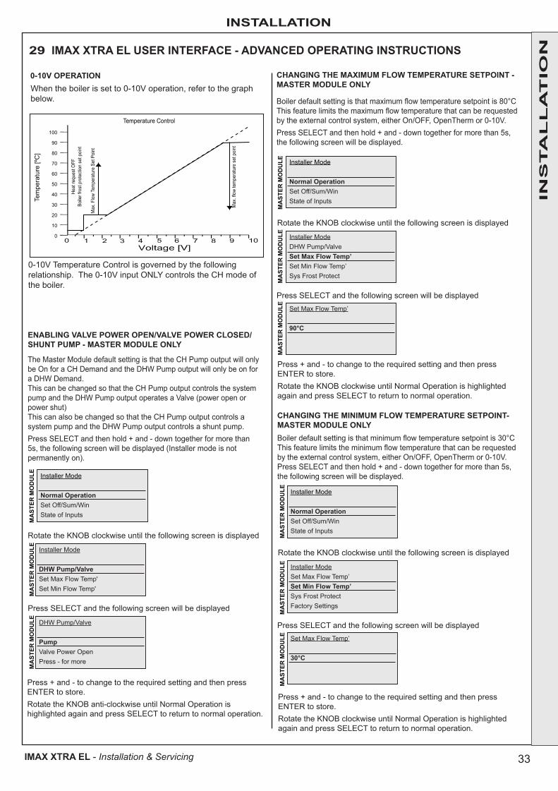
33
INSTALLATION
IMAX XTRA EL - Installation & Servicing
29 IMAX XTRA EL USER INTERFACE - ADVANCED OPERATING INSTRUCTIONS
0-10V OPERATION
100
90
80
70
60
50
40
30
20
10
0M
ax. f
low
tem
pera
ture
set
poi
nt
Heat
requ
est O
FFBo
iler f
rost
pro
tect
ion
set p
oint
Max
. Flo
w Te
mpe
ratu
re S
et P
oint
Temperature Control
Tem
pera
ture
[ºC
]
0-10V Temperature Control is governed by the following relationship. The 0-10V input ONLY controls the CH mode of the boiler.
When the boiler is set to 0-10V operation, refer to the graph below.
ENABLING VALVE POWER OPEN/VALVE POWER CLOSED/SHUNT PUMP - MASTER MODULE ONLY
The Master Module default setting is that the CH Pump output will only be On for a CH Demand and the DHW Pump output will only be on for a DHW Demand.This can be changed so that the CH Pump output controls the system pump and the DHW Pump output operates a Valve (power open or power shut)This can also be changed so that the CH Pump output controls a system pump and the DHW Pump output controls a shunt pump.Press SELECT and then hold + and - down together for more than 5s, the following screen will be displayed (Installer mode is not permanently on).
Rotate the KNOB clockwise until the following screen is displayed
Installer Mode
DHW Pump/ValveSet Max Flow Temp'Set Min Flow Temp'
Press SELECT and the following screen will be displayed
DHW Pump/Valve
PumpValve Power OpenPress - for more
Press + and - to change to the required setting and then press ENTER to store.Rotate the KNOB anti-clockwise until Normal Operation is highlighted again and press SELECT to return to normal operation.
Installer Mode
Normal OperationSet Off/Sum/WinState of Inputs
MA
STER
MO
DU
LEM
AST
ER M
OD
ULE
MA
STER
MO
DU
LE
CHANGING THE MAXIMUM FLOW TEMPERATURE SETPOINT - MASTER MODULE ONLY
Installer Mode
Normal OperationSet Off/Sum/WinState of Inputs
Boiler default setting is that maximum flow temperature setpoint is 80°CThis feature limits the maximum flow temperature that can be requested by the external control system, either On/OFF, OpenTherm or 0-10V.Press SELECT and then hold + and - down together for more than 5s, the following screen will be displayed.
Rotate the KNOB clockwise until the following screen is displayed
Installer ModeDHW Pump/ValveSet Max Flow Temp’Set Min Flow Temp’Sys Frost Protect
Press SELECT and the following screen will be displayedSet Max Flow Temp’ 90°C
Press + and - to change to the required setting and then press ENTER to store.Rotate the KNOB clockwise until Normal Operation is highlighted again and press SELECT to return to normal operation.
MA
STER
MO
DU
LEM
AST
ER M
OD
ULE
MA
STER
MO
DU
LEM
AST
ER M
OD
ULE
MA
STER
MO
DU
LEM
AST
ER M
OD
ULE
CHANGING THE MINIMUM FLOW TEMPERATURE SETPOINT-MASTER MODULE ONLY
Installer Mode
Normal OperationSet Off/Sum/WinState of Inputs
Boiler default setting is that minimum flow temperature setpoint is 30°CThis feature limits the minimum flow temperature that can be requested by the external control system, either On/OFF, OpenTherm or 0-10V.Press SELECT and then hold + and - down together for more than 5s, the following screen will be displayed.
Rotate the KNOB clockwise until the following screen is displayed
Installer ModeSet Max Flow Temp’Set Min Flow Temp’Sys Frost ProtectFactory Settings
Press SELECT and the following screen will be displayedSet Max Flow Temp’ 30°C
Press + and - to change to the required setting and then press ENTER to store.Rotate the KNOB clockwise until Normal Operation is highlighted again and press SELECT to return to normal operation.
INS
TA
LL
AT
ION
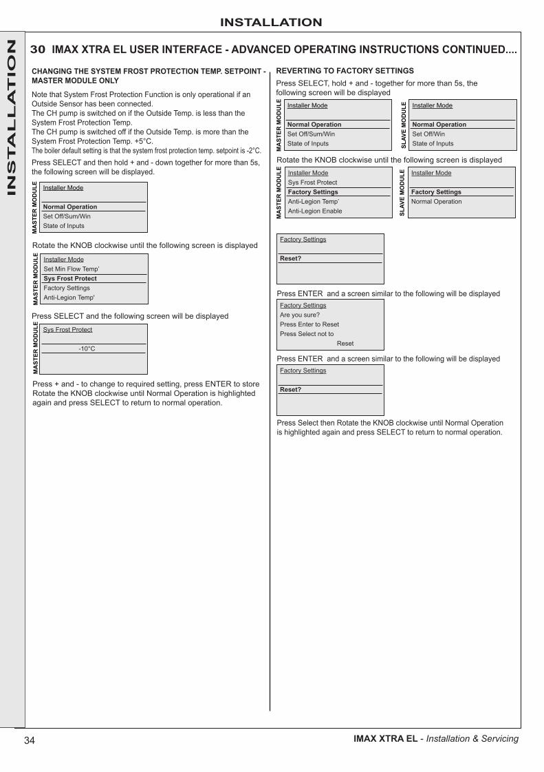
34
INSTALLATION
IMAX XTRA EL - Installation & Servicing
30 IMAX XTRA EL USER INTERFACE - ADVANCED OPERATING INSTRUCTIONS CONTINUED....M
AST
ER M
OD
ULE
MA
STER
MO
DU
LEM
AST
ER M
OD
ULE
SLAV
E M
OD
ULE
SLAV
E M
OD
ULE
MA
STER
MO
DU
LEM
AST
ER M
OD
ULE
CHANGING THE SYSTEM FROST PROTECTION TEMP. SETPOINT - MASTER MODULE ONLY
Installer Mode
Normal OperationSet Off/Sum/WinState of Inputs
Installer Mode
Normal OperationSet Off/Sum/WinState of Inputs
Installer Mode
Normal OperationSet Off/WinState of Inputs
Note that System Frost Protection Function is only operational if an Outside Sensor has been connected.The CH pump is switched on if the Outside Temp. is less than the System Frost Protection Temp.The CH pump is switched off if the Outside Temp. is more than the System Frost Protection Temp. +5°C.The boiler default setting is that the system frost protection temp. setpoint is -2°C.Press SELECT and then hold + and - down together for more than 5s, the following screen will be displayed.
Rotate the KNOB clockwise until the following screen is displayed
Installer ModeSet Min Flow Temp’Sys Frost ProtectFactory SettingsAnti-Legion Temp'
Press SELECT and the following screen will be displayed
Sys Frost Protect -10°C
Press + and - to change to required setting, press ENTER to storeRotate the KNOB clockwise until Normal Operation is highlighted again and press SELECT to return to normal operation.
REVERTING TO FACTORY SETTINGSPress SELECT, hold + and - together for more than 5s, the following screen will be displayed
Rotate the KNOB clockwise until the following screen is displayedInstaller ModeSys Frost ProtectFactory SettingsAnti-Legion Temp’Anti-Legion Enable
Installer Mode
Factory SettingsNormal Operation
Factory Settings Reset?
Press ENTER and a screen similar to the following will be displayedFactory SettingsAre you sure?Press Enter to ResetPress Select not to Reset
Press ENTER and a screen similar to the following will be displayedFactory Settings Reset?
Press Select then Rotate the KNOB clockwise until Normal Operation is highlighted again and press SELECT to return to normal operation.
INS
TA
LL
AT
ION

35
INSTALLATION
IMAX XTRA EL - Installation & Servicing
DISABLING THE ANTI-LEGIONELLA FUNCTION - MASTER MODULE ONLY
Installer Mode
Normal OperationSet Off/Sum/WinState of Inputs
Note that the Anti-Legionella Temperature Function is only operational if a Domestic Hot Water Thermistor has been connected.Care should be taken in disabling this function as an unsafe condition could result.Press SELECT and then hold + and - down together for more than 5s, the following screen will be displayed
Rotate the KNOB clockwise until the following screen is displayed
Installer ModeAnti-Legion Temp’Anti-Legion EnableNormal Operation
Press SELECT and the following screen will be displayedAnti-Legion Enable OnOff
Press + and - to change to required setting then press ENTER to store.Rotate the KNOB clockwise until Normal Operation is highlighted again and press SELECT to return to normal operation.
31 IMAX XTRA EL USER INTERFACE - ADVANCED OPERATING INSTRUCTIONS CONTINUED....
CHANGING THE ANTI-LEGIONELLA TEMPERATURE - MASTER MODULE ONLY
Installer Mode
Normal OperationSet Off/Sum/WinState of Inputs
Note Anti-Legionella Temp. Function is only operational if a DHW Thermistor has been connected.Care should be taken reducing this temp. as unsafe conditions could result.Press SELECT and then hold + and - down together for more than 5s, the following screen will be displayed.
Rotate the KNOB clockwise until the following screen is displayedInstaller ModeFactory SettingsAnti-Legion Temp’Anti-Legion EnableNormal Operation
Press SELECT and the following screen will be displayed
Anti-Legion Temp’ 70°C
Press + and - to change to required setting, press ENTER to store.Rotate the KNOB clockwise until Normal Operation is highlighted again and press SELECT to return to normal operation.
MA
STER
MO
DU
LEM
AST
ER M
OD
ULE
MA
STER
MO
DU
LE
MA
STER
MO
DU
LEM
AST
ER M
OD
ULE
MA
STER
MO
DU
LE
INS
TA
LL
AT
ION

36
INSTALLATION
IMAX XTRA EL - Installation & Servicing
32 IMAX XTRA EL WITH EXTERNAL CONTROLS VIA SWITCHED LIVE, 0-10V INPUT OR OPENTHERM - DEMAND INPUTS ON MASTER MODULE ONLY
EXTERNAL CONTROLS - VIA OPENTHERM
EXTERNAL CONTROLS - VIA 0-10V INPUT, CH ONLY
EXTERNAL CONTROLS - VIA SWITCHED LIVE
Note that the boiler requires a 2 minute pump overrun period.
The boiler warranty will be invalid if this is not provided.
It is recommended that the pump overrun functionality is achieved by connecting the pump or pump control to the boiler CH Pump connections (see diagram), although this functionality can be replicated with external controls (for example a Building Management System).
If the CH Pump connection is used and the electrical current draw is 1.3A inductive or less then the pump may be connected directly into the CH Pump connection.
If the current draw is more than this then an external relay or contactor should be operated by the CH Pump connection, with the external relay then powering the pump
For DHW operation, the DHW enable signal and Tank Sensor must always be present.
0-10+0-10-DHW
+DHW
-OW
C+OW
C-OT+OT-
PWM
GND
INTINT
LOCKOUTLOCKOUTBURNER ONBURNER ON
NL NOL NC
NLLNLIVE OUTCH CALLLIVE OUTDHW
CALL
HEATDEM
AND230v50Hz
MAINS
IN230v50Hz
DHWPUM
P/VALVE
CH/BOILERPUM
P
VOLTSFREECONTACTS
INTER/LOCK
PUMP
CONTROL
0-10vINPUT
TANKSENSOR
OUTSIDESENSOR
OPENTHERM
pumpcontrol
DHW TankSensor (Opt)supplyCH switched
liveDHW switchedlive enable (opt)
0-10+0-10-DHW
+DHW
-OW
C+OW
C-OT+OT-
PWM
GND
INTINT
LOCKOUTLOCKOUTBURNER ONBURNER ON
NL NOL NC
NLLNLIVE OUTCH CALLLIVE OUTDHW
CALL
HEATDEM
AND230v50Hz
MAINS
IN230v50Hz
DHWPUM
P/VALVE
CH/BOILERPUM
P
VOLTSFREECONTACTS
INTER/LOCK
PUMP
CONTROL
0-10vINPUT
TANKSENSOR
OUTSIDESENSOR
OPENTHERM
0-10V0 10
pumpcontrolsupply
0-10+0-10-DHW
+DHW
-OW
C+OW
C-OT+OT-
PWM
GND
INTINT
LOCKOUTLOCKOUTBURNER ONBURNER ON
NL NOL NC
NLLNLIVE OUTCH CALLLIVE OUTDHW
CALL
HEATDEM
AND230v50Hz
MAINS
IN230v50Hz
DHWPUM
P/VALVE
CH/BOILERPUM
P
VOLTSFREECONTACTS
INTER/LOCK
PUMP
CONTROL
0-10vINPUT
TANKSENSOR
OUTSIDESENSOR
OPENTHERM
openthermmaster
- +
pumpcontrolsupply
INS
TA
LL
AT
ION

37
INSTALLATION
IMAX XTRA EL - Installation & Servicing
33 COMMISSIONING AND TESTING
A. ELECTRICAL INSTALLATION
1. Checks to ensure electrical safety should be carried out by a competent person.
2. ALWAYS carry out the preliminary electrical system checks, i.e. earth continuity, polarity, resistance to earth and short circuit, using a suitable meter.
3. From turning the power on the fan will run for 4.5mins if in standby mode.
WARNING. Whilst effecting the required gas soundness test and purging air from the gas installation, open all windows and doors, extinguish naked lights and DO NOT SMOKE.
B. GAS INSTALLATION 1. The whole of the gas installation, including the meter,
should be inspected and tested for soundness and then purged in accordance with the recommendations of the relevant standards listed on page 4, by the installer.
In IE refer to I.S.813:2002.
34 INITIAL LIGHTINGEnsure the individual boiler modules are commissioned separately to avoid cross contamination of flue products. To facilitate this, ensure the SLAVE boiler is set to Standby (see user manual) and set the MASTER boiler to winter mode.
1. Check that the system has been filled and the boiler is not air locked - air in the boiler could damage the heat exchanger.
2. Check that all the drain cocks are closed and any valves in the flow and return are open.
3. Check that the GAS SERVICE COCK IS ON.4. Fill the condensate trap with water before putting the unit
into operation (see Frame 54 for condensate trap removal). 5. Check the indication on the pressure gauge. If the system
pressure is less than 1 bar the installation should be filled up first.
6. Switch the electricity supply ON and check that all the external controls are calling for heat.
7. The boiler will commence the ignition sequence. If after 5 attempts the boiler has failed to light then it will lock out. Press the reset button to restart the ignition sequence.
8. Fit a flue sampling probe on the flue adapter after ignition, refer to Page 5.
9. Operate the boiler at max rate for 10 mins (refer to Table 1 - Performance Data) and check the gas rate if a meter is available. This should be at least 90% of the nominal, refer to Frame 39.
10. Check the CO2% level at max, referring to Table below. Then check the CO2% level at min.
11. Once this has been completed, repeat this process but set the SLAVE boiler to winter mode and the MASTER boiler to standby.
12. Once completed, set both boilers to winter mode.
IMAX XTRA EL ~ Flue CO2 % measurements (hot condition)
715 790 940 1090 1240
Max Rate* (100%) 9.5% (±0.5%)
Min Rate* (20%) 9.0% (±0.5%)ADJUSTING THE CO2%
Note. Turning the Throttle and Offset anti clockwise will increase the CO2.Turning the Throttle and Offset clockwise will decrease the CO2.
If the CO2% is outside of these limits, the gas valve needs to be adjusted. If the max CO2 % needs adjustment, this is altered by the throttle screw on the front of the gas valve.
If the min CO2% needs adjustment, this is altered by the offset screw. When making CO2 adjustments, the max must be checked or adjusted BEFORE checking and if necessary adjusting the min CO2.
Once the CO2 has been set, check the CO/CO2 ratio. This must not exceed 0.004. If the CO/CO2 ratio is above 0.004 and the CO2 levels at max and min are correct, switch off the appliance and contact Ideal Boilers.
Refer to Frame 39, Servicing Schedule.
Throttle
Offset
Slide Cover(to access offset
adjustment)
* When testing Max & Min Rates; Ensure the controls displayshows 100% or 20% burner power respectively.
INS
TA
LL
AT
ION

38
INSTALLATION
IMAX XTRA EL - Installation & Servicing
35 OPERATING SEQUENCE
Standby
yes
yes
yes
yes
yes
yes
yes
yes
no
yes
no
no
no
no
no
no
no
no
noyes
yes
Heat demand on?
Temp. < setpoint?
APS openfan stand-off?
APSclosed?
Demandoff or Temp. >setpoint?
Heat Demand Off?
Pump off
Flame detected?
Demand On& Temp. <Set point & Anti-cycle
done?
Fan On10s Fan Pre-purge
Pump On
Fan on
Spark Generator OnGas Valve On
5s Ignition Period
Burner Output controlled relative toHeat Demand by varying Fan Speed
Burner On
Spark Generator Off1st Stabilisation Period
Gas Valve Off
Post Purge
Fan Off
Pump Overrun
Note1. The fan runs for 4 mins after the burner
switches off
Note2. Ignition cycle occurs 5 times before
lockout
Standby
25 secs?
25 secs?
Error
Error
INS
TA
LL
AT
ION
39
INSTALLATION
IMAX XTRA EL - Installation & Servicing
ROUTINE OPERATIONDraw the attention of the boiler owner or his representative to the User Guide. Give a practical demonstration of the lighting and shutting down of the boiler.
Describe the function of the boiler and system controls and show how they are adjusted and used.
Hand these Installation and Servicing/User's Instructions and to the customer and request him to keep them in a safe place for ready reference. For IE, it is necessary to complete a “Declaration of Conformity” to indicate compliance to the appropriate standard.
IMPORTANT. Point out to the owner that the boiler must have regular maintenance and cleaning, at least annually, in order to ensure reliable and efficient operation. Regular attention
Make the following checks for correct operation.
1. The correct operation of ANY secondary system controls should be proved. Operate each control separately and check that the main burner or circulating pump, as the case may be, responds.
2. Water circulation system;
a. With the system HOT examine all water connections for soundness.
b. With the system still HOT, turn off the gas, water and electricity supplies to the boiler and drain down to complete the flushing process.
c. Refill and vent the system, clear all air locks and again check for water soundness.
d. Balance the system.
3. Check the condensate drain for leaks and check it is discharging correctly.
4. Finally set the controls to the User’s requirements.
Note. If an optional programmer kit is fitted then refer to the instructions supplied with the kit.
36 GENERAL CHECKS
37 HANDING OVER
will also prolong the life of the boiler and should preferably be performed at the end of the heating season.
After installation and commissioning please complete the Commissioning Sheet, at the rear of this book, before handover to the customer. For IE, its is necessary to complete a “Declaration of Conformity” to indicate compliance to I.S. 813:2002.
Recommend that a contract for this work should be made with the regional gas authority or a Gas Safe Registered Engineer. In IE servicing work must be carried out by a competent person.
INS
TA
LL
AT
ION

40
SERVICING
IMAX XTRA EL - Installation & Servicing
38 SAFETYIt is the law that any service work must be carried out by a Gas Safe Registered Engineer. In IE service work must be carried out by a competent person.WARNING. Always turn off the gas supply at the gas service cock, and switch off and disconnect the electricity supply to the appliance and any external controls before servicing or replacing components.To replace parts in the water circuit, it will be necessary to isolate the water and drain the boiler.NOTE.When the burner switch is in the off position the boiler control module remains live.IMPORTANT.After completing the servicing or replacement of components always:• Test for gas soundness.
• Check the water system is correctly filled and free of air. Air in the boiler could cause damage to the heat exchanger.
• Check the jacket front panel is correctly fitted. Fit the controls cover in place.
• With the system hot examine all water connections for soundness.
• Check the gas rate and measure the combustion CO/CO2 content. The CO/CO2 ratio of the flue gas should not be greater than 0.004 ratio and the CO2 should match the values given in Frame 34.
• Carry out functional checks as appropriate.• Ensure the boiler has adequate ventilation for any gas
remaining within unisolated pipework.Note. When undertaking any servicing or replacement of parts it is essential that any gasket or seal is checked for signs of wear or damage and is replaced as necessary.
SE
RV
ICIN
G

41
SERVICING
IMAX XTRA EL - Installation & Servicing
39 SERVICING SCHEDULE
Ensure this process is repeated for both the MASTER and SLAVE Module separately, refer to page 3.
To ensure the continued safe and efficient operation of the appliance it is recommended that it is checked at regular intervals and serviced as necessary. The frequency of servicing will depend upon the installation condition and usage but should be carried out at least annually.
Ideal Boilers does not accept any liability resulting from the use of unauthorised parts or the repair and servicing of appliances not carried out in accordance with the Company’s recommendations and specifications.
Note. Some aluminium oxide build-up within the heat exchanger assembly is quite normal with this type of condensing boiler. Though removal and cleaning is recommended annually, the heat exchanger, sump and condensate trap must be inspected and cleaned after a maximum of 2 years operation.
1. Light the boiler and carry out function checks, noting any operational faults.
2. Run the boiler for 10 minutes and then check the gas consumption rate. Refer to procedure opposite on how to force the burner to maximum rate.
3. Connect a suitable gas analyser to the sampling point fitted in the flue adapter. For correct boiler operation the CO/CO2 ratio of the flue gas should not be greater than 0.004 ratio and the CO2 values should match those in table 1. If this is the case the gas input is at least 90% of the nominal.
4. Remove and clean the burner. Refer to Frame 42.
5. Inspect the heat exchanger through the burner opening. If there are signs of aluminium oxide build up, spray water down the flueways. Refer to Frame 42.
6. Remove the sump cover and scrape out any deposits. Refer to Frame 45.
7. Remove the condensate trap and flush through with water. Refer to Frame 46.
8. Check that the flue terminal is unobstructed and that the flue system is sealed correctly.
9. Remove the gas valve filter and check that there is no debris. Clean or replace as necessary. Refer to Frame 44
10. Whilst burner is removed, ensure spark gap between electrodes is 5mm (±1mm).
11. After completion of servicing refer to Frame 38 for reference to final safety checks.
12. Complete the service record in the Rear of this book.
Ideal imax XLM 1240 kW
Normal OperationSet Off/Sum/WinState of Inputs
Ideal imax XLS 1240 kW
Normal OperationSet Off/WinState of Inputs
Rotate KNOB clockwise until the following screen is displayed
Set Off/Sum/WinSummerWinterMinimumPress - for more
Set Off/WinStandbyWinterMinimumPress - for more
Set Off/Sum/WinMinimumMaximum
Press - for more
Set Off/WinMinimumMaximum
Press - for more
Press SELECT and the following screen will be displayed
Press + and - until the following screen is displayed.
Press ENTER and the boiler will go to Maximum Rate for 10 minutes.Operation will be automatically reset at the end of 10 minutes.To set to minimum, repeat the above selecting "minimum" setting.
SETTING TO FIXED OUTPUTSThe individual Master and Slave modules may be set to Maximum or Minimum rate independently on their respective User Interface.
Ensure that there is a current CH demand to the boiler (e.g. the CH Switched Live is on).
Ensure that there is sufficient heating load on the boiler to allow it to run at maximum rate.
Wait until the boiler is at 100% then press SELECT and the following screen will be displayed.
The kW output number in the 1st line will vary depending on the maximum output of the boiler.
SE
RV
ICIN
G
Do we need a statement that gaskets must be changed after say 3 or 5 years (as Buderus)?
The problem is how will the engineer know if it is 3 or 5 years since the gaskets were changed?
HS to answer.
Note.When undertaking any servicing or replacement of parts it is essential that any gasket or seal is checked for signs of wear or damage and is replaced as necessary.
SLAV
E M
OD
ULE
MA
STER
MO
DU
LE
Ideal imax XLM 1240 kWSet DHW Temp’Set Off/Sum/WinState of InputsState of Outputs
Ideal imax XLS 1240 kWSet DHW Temp’Set Off/WinState of InputsState of OutputsSL
AVE
MO
DU
LE
MAS
TER
MO
DULE
MAS
TER
MO
DULE
MAS
TER
MO
DULE
SLAV
E M
ODU
LESL
AVE
MO
DULE

42
SERVICING
IMAX XTRA EL - Installation & Servicing
40 CASING REMOVAL
TO REMOVE FRONT AND SIDE PANELS
1. Refer to frame 38.
2. Lift the control pod upwards to disengage. This can then be located in the raised position using the location hooks.
3. Remove the 2 securing screws from the front panel.
4. Angle the front panel forward and lift to disengage the panel and remove.
5. Slide the front side panel forward and lift to disengage from the fixing locations
6. Slide the rear side panel forward and lift to disengage from the fixing locations.
7. Repeat steps 5 and 6 to remove the remaining side panels.
8. Re-fit in reverse order. Note; only the two front side panels have
noise dampening insulation fitted
SE
RV
ICIN
G
41 REMOVAL OF BURNER MANIFOLD
1. Refer to Frames 38 & 40.2. Remove the four nuts securing the burner hood elbow to
the heat exchanger.3. Remove the four bolts securing the burner hood elbow to
the interface plate.4. Lift the burner hood elbow and carefully clear the heat
exchanger studs.5. To Refit: Inspect the sealing gaskets for damage and
replace as necessary.
6. Align the burner head elbow and engage the studs on the heat exchanger.
7. Loosely fit the four securing bolts to locate the elbow on the interface plate.
8. Loosely fit the four securing nuts to the heat exchanger studs.9. With all fixings in position, tighten in sequence to ensure
the burner hood elbow is correctly secured on the interface plate and the heat exchanger.
10. Check for any leakage on all seals.

43
SERVICING
IMAX XTRA EL - Installation & Servicing
42 BURNER REMOVAL / CLEANING OF BURNER & HEAT EXCHANGER
1. Refer to Frame 38.
2. Refer to Frames 40 & 41 for removal of burner manifold.
3. Draw the burner out of the heat exchanger.
4. The burner can be cleaned using compressed air or a vacuum. The metal fibre outer surface must not be brushed. If the burner is showing signs of damage it must be replaced.
5. Re-assemble in reverse order replacing any seals/gaskets which show signs of wear. When refitting, ensure the burner is correctly engaged so the burner flange fits flush into the recess.
6. Refer to Frame 38 for final safety checks.
With the burner removed the heat exchanger may now be cleaned.To remove any debris flush the heat exchanger with water, if possible from a pressurised supply, taking care to protect any electrical components against moisture. Ensure the heat exchanger is fully flushed.
SE
RV
ICIN
G
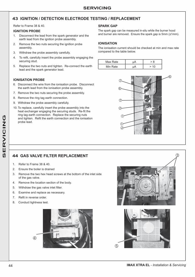
44
SERVICING
IMAX XTRA EL - Installation & Servicing
SE
RV
ICIN
G
44 GAS VALVE FILTER REPLACEMENT
43 IGNITION / DETECTION ELECTRODE TESTING / REPLACEMENT
1. Refer to Frame 38 & 40.
2. Ensure the boiler is drained
3. Remove the two hex head screws at the bottom of the inlet side of the gas valve.
4. Remove the location section of the body.
5. Withdraw the gas valve inlet filter.
6. Examine and replace as necessary.
7. Refit in reverse order.
8. Conduct tightness test.
Refer to Frame 38 & 40.
IGNITION PROBE1. Disconnect the lead from the spark generator and the
earth lead from the ignition probe assembly.
2. Remove the two nuts securing the ignition probe assembly.
3. Withdraw the probe assembly carefully.
4. To refit, carefully insert the probe assembly engaging the securing stud.
5. Replace the two nuts and tighten. Re-connect the earth lead and the spark generator lead.
IONISATION PROBE6. Disconnect the wire from the ionisation probe. Disconnect
the earth lead from the ionisation probe assembly.
7. Remove the two nuts securing the probe assembly.
8. Remove the ring tag earth connection.
9. Withdraw the probe assembly carefully.
10. To replace, carefully insert the probe assembly into the heat exchanger engaging the securing studs. Re-fit the ring tag earth connection. Replace the securing nuts and tighten. Refit the earth connection and the ionisation probe lead.
SPARK GAPThe spark gap can be measured in-situ while the burner hood and burner are removed. Ensure the spark gap is 5mm (±1mm).
IONISATIONThe ionisation current should be checked at min and max rate compared to the table below.
Max Rate μA > 8Min Rate μA > 10
SE
RV
ICIN
G

45
SERVICING
IMAX XTRA EL - Installation & Servicing
45 INSPECTING & CLEANING THE SUMP
1. Refer to Frame 38 & 40.
2. Remove the inspection cover which is secured with eight bolts.
3. The RHS inspection cover will be accessible for removal on the Master module and the LHS inspection cover will be accessible on the Slave module
4. Remove any debris and flush with water if necessary.
5. To re-fit the sump inspection panel inspect the o-ring seal for damage and replace if necessary.
6. Align the sump inspection cover and secure with the 8 bolts.
46 CLEANING CONDENSATE TRAP
1. Refer to Frame 38.
2. Unscrew the top fitting of the condensate trap.
3. Unscrew the fitting at the flue outlet drain point.
4. Unscrew the condensate outlet fitting.
5. Unscrew bracket and remove trap
6. Unscrew the base of the trap and drain into a bucket.
7. Remove all debris, flushing with water if necessary.
8. Re-fit the base of the trap.
9. Re-fit in reverse order.
10. Pour water into the flue sample point to ensure the condense trap is re-filled before the unit is operated after servicing.
SE
RV
ICIN
G
SE
RV
ICIN
G
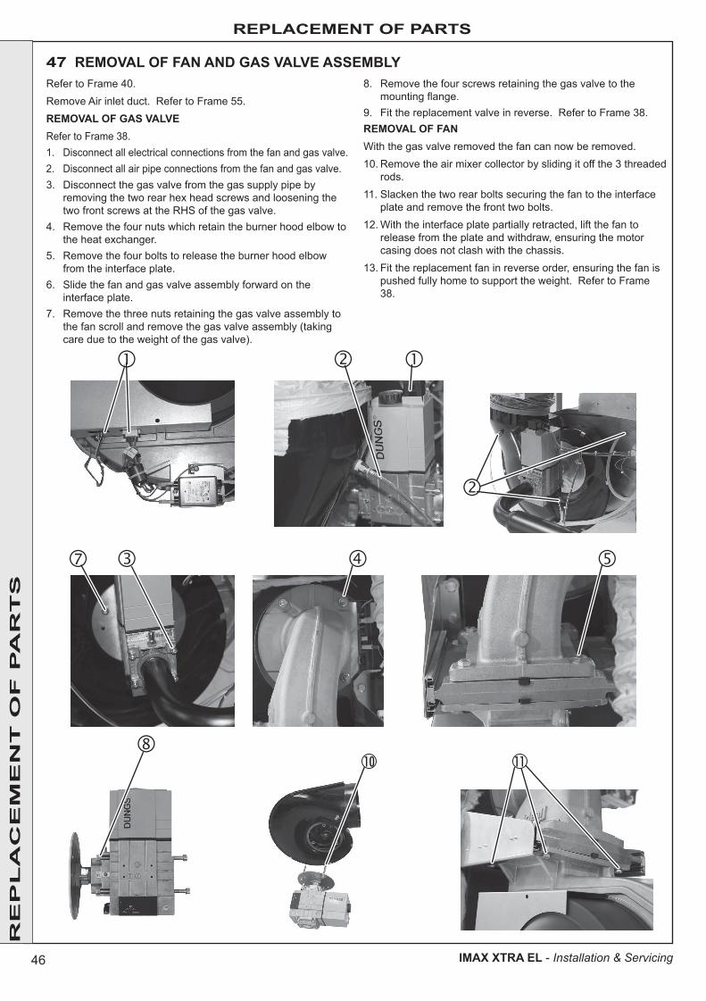
46
REPLACEMENT OF PARTS
IMAX XTRA EL - Installation & Servicing
47 REMOVAL OF FAN AND GAS VALVE ASSEMBLYRefer to Frame 40.Remove Air inlet duct. Refer to Frame 55.REMOVAL OF GAS VALVERefer to Frame 38.1. Disconnect all electrical connections from the fan and gas valve.2. Disconnect all air pipe connections from the fan and gas valve.3. Disconnect the gas valve from the gas supply pipe by
removing the two rear hex head screws and loosening the two front screws at the RHS of the gas valve.
4. Remove the four nuts which retain the burner hood elbow to the heat exchanger.
5. Remove the four bolts to release the burner hood elbow from the interface plate.
6. Slide the fan and gas valve assembly forward on the interface plate.
7. Remove the three nuts retaining the gas valve assembly to the fan scroll and remove the gas valve assembly (taking care due to the weight of the gas valve).
8. Remove the four screws retaining the gas valve to the mounting flange.
9. Fit the replacement valve in reverse. Refer to Frame 38.REMOVAL OF FANWith the gas valve removed the fan can now be removed.10. Remove the air mixer collector by sliding it off the 3 threaded
rods.11. Slacken the two rear bolts securing the fan to the interface
plate and remove the front two bolts.12. With the interface plate partially retracted, lift the fan to
release from the plate and withdraw, ensuring the motor casing does not clash with the chassis.
13. Fit the replacement fan in reverse order, ensuring the fan is pushed fully home to support the weight. Refer to Frame 38.
10 11
RE
PL
AC
EM
EN
T O
F P
AR
TS
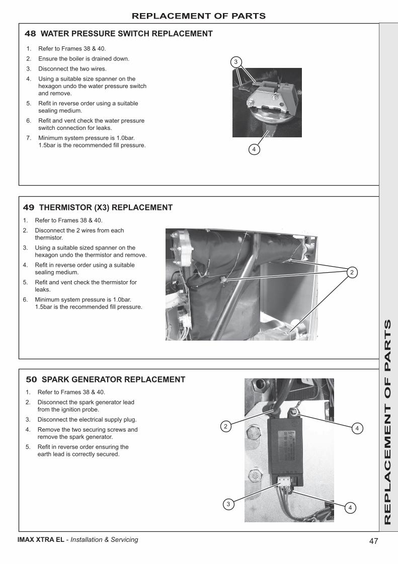
47
REPLACEMENT OF PARTS
IMAX XTRA EL - Installation & Servicing
48 WATER PRESSURE SWITCH REPLACEMENT
1. Refer to Frames 38 & 40.
2. Ensure the boiler is drained down.
3. Disconnect the two wires.
4. Using a suitable size spanner on the hexagon undo the water pressure switch and remove.
5. Refit in reverse order using a suitable sealing medium.
6. Refit and vent check the water pressure switch connection for leaks.
7. Minimum system pressure is 1.0bar. 1.5bar is the recommended fill pressure.
49 THERMISTOR (X3) REPLACEMENT1. Refer to Frames 38 & 40.
2. Disconnect the 2 wires from each thermistor.
3. Using a suitable sized spanner on the hexagon undo the thermistor and remove.
4. Refit in reverse order using a suitable sealing medium.
5. Refit and vent check the thermistor for leaks.
6. Minimum system pressure is 1.0bar. 1.5bar is the recommended fill pressure.
1. Refer to Frames 38 & 40.
2. Disconnect the spark generator lead from the ignition probe.
3. Disconnect the electrical supply plug.
4. Remove the two securing screws and remove the spark generator.
5. Refit in reverse order ensuring the earth lead is correctly secured.
50 SPARK GENERATOR REPLACEMENT
2
2
3 4
4
3
4
RE
PL
AC
EM
EN
T O
F P
AR
TS

48
REPLACEMENT OF PARTS
IMAX XTRA EL - Installation & Servicing
51 BOILER CONTROL PCB REPLACEMENT1. Refer to Frames 38 & 40.
2. Remove all PCB electrical connections.
3. Remove the PCB carefully by pulling gently towards you at each mounting point.
4. Release the PCB from the mounting posts carefully and remove.
5. To refit, align the PCB with the mounting posts and push the PCB carefully to engage the mounting posts.
6. Refit the connectors relating to the wiring diagram in Frame 24 & 25.
33
2
2
52 OT CENTER REPLACEMENT
1. Remove front panel & control pod on the Master Module (refer to Frame 40)
By removing the front panels on the Master Module it will enable access to the Slave Module OT Center.
To access the Master Module OT Centre, remove the RH side panels.
2. Squeeze tab and pull to remove connection lead.
3. Firmly pull up and down on module to remove.
4. Replace with new module after setting switches 'S1' and 'S2' according to Frame 22.
5. Plug in communication lead to either common socket.
6. Re-assemble in reverse order ensuring OT Center module is pushed fully home to its backing plate.
7. Refer to Frame 38 for final safety checks.
2
3
RE
PL
AC
EM
EN
T O
F P
AR
TS
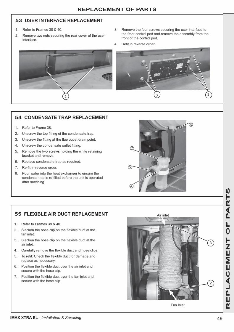
49
REPLACEMENT OF PARTS
IMAX XTRA EL - Installation & Servicing
54 CONDENSATE TRAP REPLACEMENT
1. Refer to Frame 38.
2. Unscrew the top fitting of the condensate trap.
3. Unscrew the fitting at the flue outlet drain point.
4. Unscrew the condensate outlet fitting.
5. Remove the two screws holding the white retaining bracket and remove.
6. Replace condensate trap as required.
7. Re-fit in reverse order.
8. Pour water into the heat exchanger to ensure the condense trap is re-filled before the unit is operated after servicing.
3 32
53 USER INTERFACE REPLACEMENT
1. Refer to Frames 38 & 40.
2. Remove two nuts securing the rear cover of the user interface.
3. Remove the four screws securing the user interface to the front control pod and remove the assembly from the front of the control pod.
4. Refit in reverse order.
Fan Inlet
55 FLEXIBLE AIR DUCT REPLACEMENT
1. Refer to Frames 38 & 40.
2. Slacken the hose clip on the flexible duct at the fan inlet.
3. Slacken the hose clip on the flexible duct at the air inlet.
4. Carefully remove the flexible duct and hose clips.
5. To refit: Check the flexible duct for damage and replace as necessary.
6. Position the flexible duct over the air inlet and secure with the hose clip.
7. Position the flexible duct over the fan inlet and secure with the hose clip.
3
2
Air inlet
RE
PL
AC
EM
EN
T O
F P
AR
TS

50
REPLACEMENT OF PARTS
IMAX XTRA EL - Installation & Servicing
RE
PL
AC
EM
EN
T O
F P
AR
TS
56 HIGH VOLTAGE HARNESS REPLACEMENT
1. Refer to Frames 38 & 40.
2. Remove the mains connection from the following spark generator, fan and gas valve.
3. Disconnect the harness from the ionisation assembly lead.
4. Unclip the harness tracing the route back to the control box.
5. Remove the connectors from the PCB.
6. Remove the three bottom connectors on LHS of control box .
7. Remove the earth post nut and release the earth connections.
8. Feed the harness through the control box and remove.
9. To refit feed the new harness through the control box.
10. Fit the three bottom connections and the PCB connectors.
11. Fit the earth wires and secure with the nut.
12. Feed the harness back to the components listed above. Use clips to retain in position and connect.
2
3
5
5
6
6
7
7
MASTER MODULE
SLAVE MODULE
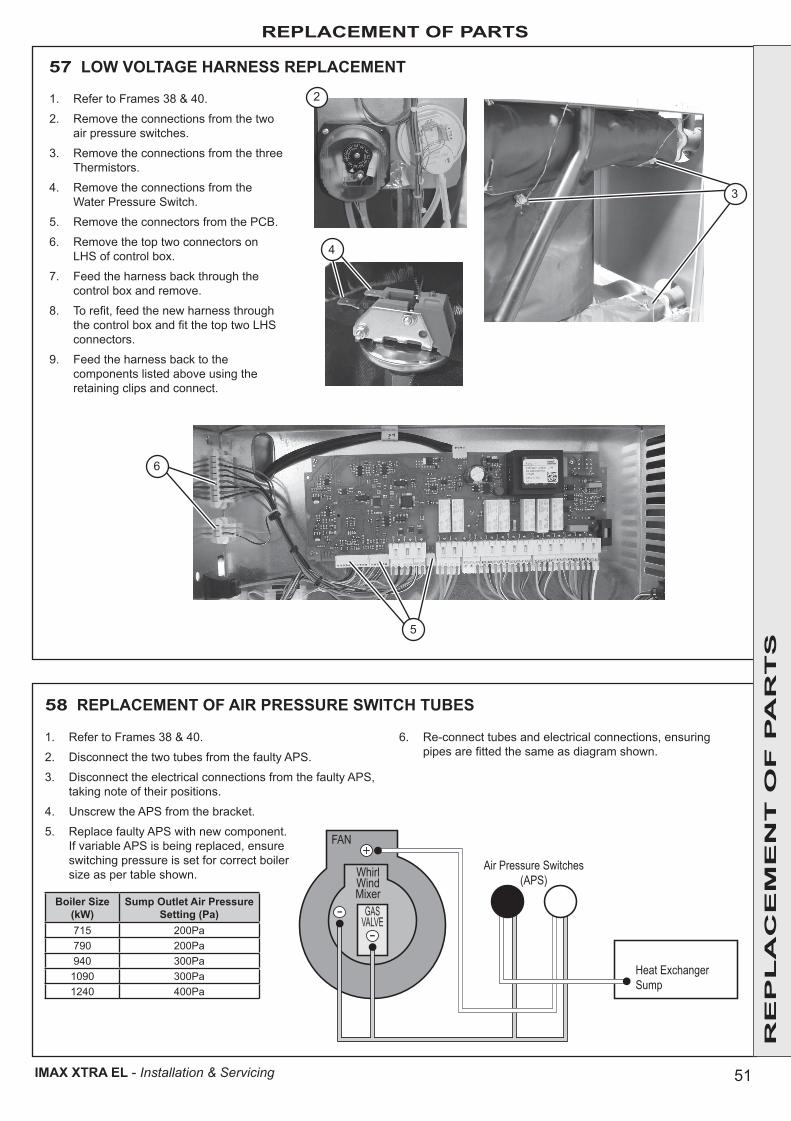
51
REPLACEMENT OF PARTS
IMAX XTRA EL - Installation & Servicing
57 LOW VOLTAGE HARNESS REPLACEMENT
58 REPLACEMENT OF AIR PRESSURE SWITCH TUBES
1. Refer to Frames 38 & 40.
2. Remove the connections from the two air pressure switches.
3. Remove the connections from the three Thermistors.
4. Remove the connections from the Water Pressure Switch.
5. Remove the connectors from the PCB.
6. Remove the top two connectors on LHS of control box.
7. Feed the harness back through the control box and remove.
8. To refit, feed the new harness through the control box and fit the top two LHS connectors.
9. Feed the harness back to the components listed above using the retaining clips and connect.
2
3
4
GASVALVE
WhirlWindMixer
FAN
Heat ExchangerSump
Air Pressure Switches(APS)
+
--
1. Refer to Frames 38 & 40.
2. Disconnect the two tubes from the faulty APS.
3. Disconnect the electrical connections from the faulty APS, taking note of their positions.
4. Unscrew the APS from the bracket.
5. Replace faulty APS with new component. If variable APS is being replaced, ensure switching pressure is set for correct boiler size as per table shown.
Boiler Size (kW)
Sump Outlet Air Pressure Setting (Pa)
715 200Pa790 200Pa940 300Pa1090 300Pa1240 400Pa
6. Re-connect tubes and electrical connections, ensuring pipes are fitted the same as diagram shown.
5
6
RE
PL
AC
EM
EN
T O
F P
AR
TS

52
FAULT FINDING FA
ULT
FIN
DIN
G F
AU
LT
FIN
DIN
G F
AU
LT
FIN
DIN
G F
AU
LT
FIN
DIN
G F
AU
LT
FIN
DIN
G F
AU
LT
FIN
DIN
G
IMAX XTRA EL - Installation & Servicing
Overheat LockoutFill System to a min. of 1.0 barVent SystemCheck Pump Spins FreeReset Boiler
59 FAULT FINDING CHART - MAIN MENU
Go to Frame 60Overheat Lockout
Go to Frame 61Ignition Lockout
Too Many ResetsTurn Boiler Power OffTurn Boiler Power On
5 resets within 15 minsTurn power off and on
Go to Frame 62False Flame Lockout
Go to Frame 63Low Water Pressure
Go to Frame 64Flame Loss
Fan FaultCheck Fan WiringCheck Fan
Go to Frame 65Fan Fault
Return Thmr FaultCheck Return Thermistor WiringCheck Return Thmr(10K @ 25°C,2K at 66°C)
Go to Frame 66Return Thermistor Fault
Outside Sensor FaultCheck Outside Sensor WiringCheck Outside Sensor(10K @ 25°C,2K at 66°C)
Go to Frame 67Outside Sensor Fault
Low Mains VoltageLess than 160VCheck Local GeneratorContact Electricity Provider
ContactElectricity Provider
PCB FaultEnsure BCC fittedReplace PCB
Replace MainPCB
Flow/Return ReversedCheck PumpCheck System Pipework
Go to Frame 68Flow/Return Reversed
Cylinder Thermistor FaultCheck Cylinder Thermistor WiringCheck Cylinder Thmr(10K @ 25°C,2K at 66°C)
Go to Frame 69 CylinderThermistor Fault
Ext’ Interlock OffExternal Interlock OperatedReset Interlock
Go to Frame 76Ext’ Interlock Off
Ignition LockoutCheck Gas to BoilerCheck Condensate PipeRefer to InstructionsReset Boiler
False Flame LockoutCheck Flame Sense ElectrodeCheck Flame Sense Electrode Wiring
Low Water PressureAir Pressure/Fan FaultCheck Air/Flue/SumpFill System to 1.0 barCheck Fan/APS,WPS,FGPS
Flame LossCheck Gas to BoilerCheck Condensate PipeCheck Flue System
Flow Thermistor FaultCheck Flow Thermistor WiringCheck Flow Thermistor(10K @ 25°C,2K at 66°C)
Go to Frame 66Flow Thermistor Fault
BCC FaultEnsure BCC fitted correctlyReplace BCC
Go to Frame 70BCC Fault
No CH but DHW OKGo to Frame 72No CH but DHW OK
No DHW but CH OKGo to Frame 73No DHW but CH OK
Blank DisplayGo to Frame 74Blank Display
Flow Temperature Setpoint cannot be increased to 90°C
Ensure Flow Temp is not limited within Installer Mode. See Frame 29
Flow Temperature Setpoint cannot be reduced to 80°C
Ensure Flow Temp is not limited within Installer Mode. Go to Frame 29.
Boiler does not respond to 0-10V Input
Go to Frame 750-10V Interface
Error 20 Go to Frame 62False Flame Lockout
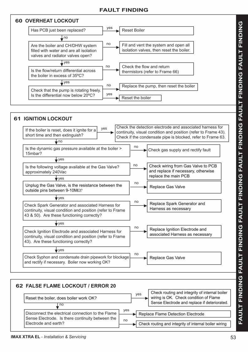
53
FAULT FINDING
FA
ULT
FIN
DIN
G F
AU
LT
FIN
DIN
G F
AU
LT
FIN
DIN
G F
AU
LT
FIN
DIN
G F
AU
LT
FIN
DIN
G F
AU
LT
FIN
DIN
G
IMAX XTRA EL - Installation & Servicing
60 OVERHEAT LOCKOUT
Has PCB just been replaced? Reset Boileryes
no
Are the boiler and CH/DHW system filled with water and are all isolation valves and radiator valves open?
Fill and vent the system and open all isolation valves, then reset the boiler.
no
yes
Is the flow/return differential across the boiler in excess of 35ºC?
Check the flow and return thermistors (refer to Frame 66)
no
yes
Check that the pump is rotating freely. Is the differential now below 20ºC?
Replace the pump, then reset the boilerno
yesReset the boiler
61 IGNITION LOCKOUT
If the boiler is reset, does it ignite for a short time and then extinguish?
Check the detection electrode and associated harness for continuity, visual condition and position (refer to Frame 43). Check if the condensate pipe is blocked, refer to Frame 63.
yes
no
Is the dynamic gas pressure available at the boiler > 15mbar?
Check gas supply and rectify faultno
yes
Is the following voltage available at the Gas Valve? approximately 240Vac
Check wiring from Gas Valve to PCB and replace if necessary, otherwise replace the main PCB
no
yes
Unplug the Gas Valve, is the resistance between the outside pins between 9-10MΩ?
Replace Gas Valveno
yes
Check Spark Generator and associated Harness for continuity, visual condition and position (refer to Frame 43 & 50). Are these functioning correctly?
Replace Spark Generator and Harness as necessary
no
yesReplace Ignition Electrode and associated Harness as necessary
noCheck Ignition Electrode and associated Harness for continuity, visual condition and position (refer to Frame 43). Are these functioning correctly?
yes
Replace Gas Valveno
Check Syphon and condensate drain pipework for blockage and rectify if necessary. Boiler now working OK?
62 FALSE FLAME LOCKOUT / ERROR 20Check routing and integrity of internal boiler wiring is OK. Check condition of Flame Sense Electrode and replace if deteriorated.
yesReset the boiler, does boiler work OK?
no
Replace Flame Detection Electrode
Check routing and integrity of internal boiler wiring
yes
no
Disconnect the electrical connection to the Flame Sense Electrode. Is there continuity between the Electrode and earth?
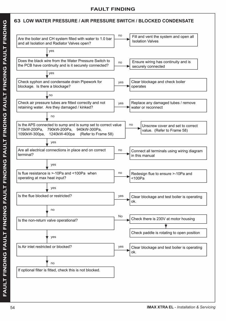
54
FAULT FINDING FA
ULT
FIN
DIN
G F
AU
LT
FIN
DIN
G F
AU
LT
FIN
DIN
G F
AU
LT
FIN
DIN
G F
AU
LT
FIN
DIN
G F
AU
LT
FIN
DIN
G
IMAX XTRA EL - Installation & Servicing
63 LOW WATER PRESSURE / AIR PRESSURE SWITCH / BLOCKED CONDENSATE
Fill and vent the system and open all Isolation Valves
no
yes
yes
no
no
yes
No
yes
no
no
no
no
yes
yes
yes
yes
Are the boiler and CH system filled with water to 1.0 bar and all Isolation and Radiator Valves open?
yes
yes
no
Ensure wiring has continuity and is securely connected
noDoes the black wire from the Water Pressure Switch to the PCB have continuity and is it securely connected?
Check syphon and condensate drain Pipework for blockage. Is there a blockage?
Clear blockage and check boiler operates
Replace any damaged tubes / remove water or reconnect
Connect all terminals using wiring diagram in this manual
Redesign flue to ensure >-10Pa and <100Pa
Clear blockage and test boiler is operating ok.
Check there is 230V at motor housing
Check paddle is rotating to open position
Clear blockage and test boiler is operating ok.
Unscrew cover and set to correct value. (Refer to Frame 58)
Check air pressure tubes are fitted correctly and not retaining water. Are they damaged / kinked?
Is the APS connected to sump and is sump set to correct value715kW-200Pa, 790kW-200Pa, 940kW-300Pa, 1090kW-300pa, 1240kW-400pa (Refer to Frame 58)
Are all electrical connections in place and on correct terminal?
Is flue resistance is >-10Pa and <100Pa when operating at max heat input?
Is the flue blocked or restricted?
Is the non-return valve operational?
Is Air inlet restricted or blocked?
If optional filter is fitted, check this is not blocked.
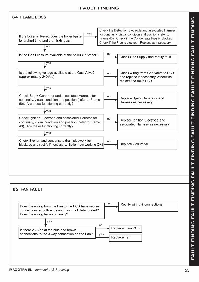
55
FAULT FINDING
FA
ULT
FIN
DIN
G F
AU
LT
FIN
DIN
G F
AU
LT
FIN
DIN
G F
AU
LT
FIN
DIN
G F
AU
LT
FIN
DIN
G F
AU
LT
FIN
DIN
G
IMAX XTRA EL - Installation & Servicing
64 FLAME LOSS
Check the Detection Electrode and associated Harness for continuity, visual condition and position (refer to Frame 43). Check if the Condensate Pipe is blocked. Check if the Flue is blocked. Replace as necessary
yesIf the boiler is Reset, does the boiler Ignite for a short time and then Extinguish
no
Check Gas Supply and rectify faultnoIs the Gas Pressure available at the boiler > 15mbar?
yes
Is the following voltage available at the Gas Valve? (approximately 240Vac)
Check wiring from Gas Valve to PCB and replace if necessary, otherwise replace the main PCB
no
yes
Check Spark Generator and associated Harness for continuity, visual condition and position (refer to Frame 50). Are these functioning correctly?
Replace Spark Generator and Harness as necessary
no
yes
Check Ignition Electrode and associated Harness for continuity, visual condition and position (refer to Frame 43). Are these functioning correctly?
Replace Ignition Electrode and associated Harness as necessary
no
yes
Check Syphon and condensate drain pipework for blockage and rectify if necessary. Boiler now working OK? Replace Gas Valve
no
65 FAN FAULT
Rectify wiring & connectionsnoDoes the wiring from the Fan to the PCB have secure connections at both ends and has it not deteriorated? Does the wiring have continuity?
yes
Replace main PCB
Replace Fan
no
yesIs there 230Vac at the blue and brown connections to the 3 way connection on the Fan?

56
FAULT FINDING FA
ULT
FIN
DIN
G F
AU
LT
FIN
DIN
G F
AU
LT
FIN
DIN
G F
AU
LT
FIN
DIN
G F
AU
LT
FIN
DIN
G F
AU
LT
FIN
DIN
G
IMAX XTRA EL - Installation & Servicing
66 THERMISTOR FAULT
Fit a new thermistornoDisconnect the electrical connection to the Flow/Return/Heat Exchanger thermistor as required and check the resistance using a suitable multimeter connected across the thermistor's terminal pins.
At 25°C expect 9,700 - 10,300 ΩAt 60°C expect 2,400 - 2,600 ΩAt 85°C expect 1,000 - 1,100 ΩIs the thermistor value correct?
yes
Check and replace wiring as necessary
Replace main PCB
no
yesIs there continuity between the PCB and the thermistor?
67 OUTSIDE SENSOR FAULT
Fit a new Outside Sensorno
Disconnect the wires to the Outside Sensor. Check the resistance using a suitable multimeter connected across the thermistor’s terminal pins.At 0°C expect 32,000 - 33,000 ΩAt 10°C expect 19,000 - 21,000 ΩAt 20°C expect 12,000 - 13,000 ΩIs the thermistor value correct?
yes
Ensure the wiring has continuity and is securely connected
noDoes the Outside Sensor wiring between the boiler terminal strip and the PCB have continuity and is it securely connected?
yes
Replace main PCB
Securely connect the wiring at both the boiler and Outside Sensor
noIs the wiring securely connected at both the boiler and Outside Sensor?
yes
68 FLOW/RETURN REVERSED
Check that the system pipework is correct
Is the Pump connected the correct way?
yes
Reverse Pumpno

57
FAULT FINDING
FA
ULT
FIN
DIN
G F
AU
LT
FIN
DIN
G F
AU
LT
FIN
DIN
G F
AU
LT
FIN
DIN
G F
AU
LT
FIN
DIN
G F
AU
LT
FIN
DIN
G
IMAX XTRA EL - Installation & Servicing
69 CYLINDER THERMISTOR FAULT
Fit a new cylinder thermistornoDisconnect the wires to the cylinder thermistor. Check the resistance using a suitable multimeter connected across the thermistor’s terminal pins.At 25°C expect 9,700 - 10,300 ΩAt 60°C expect 2,400 - 2,600 ΩAt 85°C expect 1,000 - 1,100 ΩIs the thermistor value correct?
yes
Ensure the wiring has continuity and is securely connected
no
Does the cylinder thermistor wiring between the boiler terminal strip and the PCB have continuity and is it securely connected? Replace main PCB
Connect the thermistorno
Is a DHW Thermistor connected to the boiler?
yes
Securely connect the wiring at both the boiler and cylinder thermistor
noIs the wiring securely connected at both the boiler and cylinder thermistor?
yes
yes
70 BCC FAULT
Securely attach the correct BCC for the boiler onto the PCB. Note: ensure the correct orientation of the BCC by placing the side marked “TOP” upwards.
noIs the correct BCC for the boiler securely inserted into the slot at the front left of the PCB?(identified by the label on the BCC)
yes
Replace the BCC with a new BCC (that is correct for the boiler). After switching power on and resetting the boiler does the fault disappear?
Replace main PCBno
71 OT CENTER FAULT FINDING
1. Top LED (Red) Regular flashing indicates correct communication with OT Center
and electrical control module located to the right of the OT Center. If regular flashing is not evident check:
a. Integrity of wiring between OT Center and PCB.
b. Correct communication with PCB. (Refer to Frame 52 & 56).
2. Middle LED (Yellow) This indicates failure of boiler. If yellow LED is showing check fault
finding codes.
3. Bottom LED (Green) Regular flashing indicates correct Center communication with OT
Center and connecting OT Center on adjoining module. If regular flashing is not evident check correct fitment of both OT Centers and adjoining communications lead. (Refer to Frame 52 & 56).
1
2
3
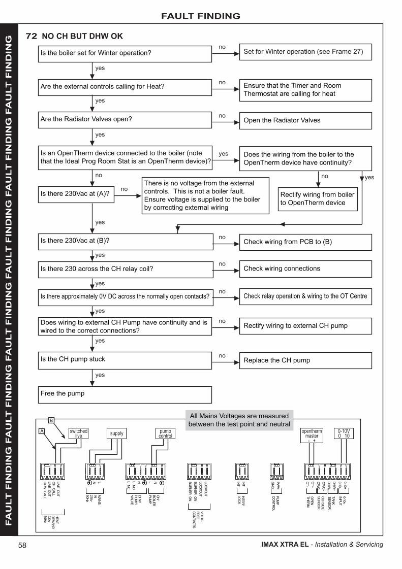
58
FAULT FINDING FA
ULT
FIN
DIN
G F
AU
LT
FIN
DIN
G F
AU
LT
FIN
DIN
G F
AU
LT
FIN
DIN
G F
AU
LT
FIN
DIN
G F
AU
LT
FIN
DIN
G
IMAX XTRA EL - Installation & Servicing
72 NO CH BUT DHW OK
Set for Winter operation (see Frame 27)no
Is the boiler set for Winter operation?
yes
Are the external controls calling for Heat? Ensure that the Timer and Room Thermostat are calling for heat
no
yes
Are the Radiator Valves open? Open the Radiator Valvesno
yes
Is an OpenTherm device connected to the boiler (note that the Ideal Prog Room Stat is an OpenTherm device)?
Does the wiring from the boiler to the OpenTherm device have continuity?
yes
no
Rectify wiring from boiler to OpenTherm device
no
Is there 230Vac at (A)?There is no voltage from the external controls. This is not a boiler fault. Ensure voltage is supplied to the boiler by correcting external wiring
no
yes
Is there 230Vac at (B)?
Is there 230 across the CH relay coil?
Is there approximately 0V DC across the normally open contacts?
Check wiring from PCB to (B)
Check wiring connections
Check relay operation & wiring to the OT Centre
no
no
no
yes
yes
yes
yes
Does wiring to external CH Pump have continuity and is wired to the correct connections?
Rectify wiring to external CH pumpno
yes
Is the CH pump stuck Replace the CH pumpno
yes
Free the pump
0-10+0-10-DHW
+DHW
-OW
C+OW
C-OT+OT-
PWM
GND
INTINT
LOCKOUTLOCKOUTBURNER ONBURNER ON
NL NOL NC
NLLNLIVE OUTCH CALLLIVE OUTDHW
CALL
HEATDEM
AND230v50Hz
MAINS
IN230v
DHW
50Hz
PUMP/
VALVE
CH/BOILERPUM
P
VOLTSFREECONTACTS
INTER/LOCK
PUMP
CONTROL
0-10vINPUT
TANKSENSOR
OUTSIDESENSOR
OPENTHERM
switchedlive
pumpcontrol
0-10V0 10
openthermmaster
- +supply
All Mains Voltages are measured between the test point and neutral
A
B
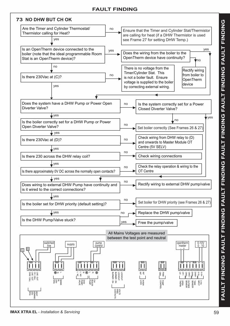
59
FAULT FINDING
FA
ULT
FIN
DIN
G F
AU
LT
FIN
DIN
G F
AU
LT
FIN
DIN
G F
AU
LT
FIN
DIN
G F
AU
LT
FIN
DIN
G F
AU
LT
FIN
DIN
G
IMAX XTRA EL - Installation & Servicing
0-10+0-10-DHW
+DHW
-OW
C+OW
C-OT+OT-
PWM
GND
INTINT
LOCKOUTLOCKOUTBURNER ONBURNER ON
NL NOL NC
NLLNLIVE OUTCH CALLLIVE OUTDHW
CALL
HEATDEM
AND230v50Hz
MAINS
IN230v
DHW
50Hz
PUMP/
VALVE
CH/BOILERPUM
P
VOLTSFREECONTACTS
INTER/LOCK
PUMP
CONTROL
0-10vINPUT
TANKSENSOR
OUTSIDESENSOR
OPENTHERM
switchedlive
pumpcontrol
0-10V0 10
openthermmaster
- +supply
73 NO DHW BUT CH OK
Ensure that the Timer and Cylinder Stat/Thermistor are calling for heat (if a DHW Thermistor is used see Frame 27 for setting DHW Temp.)yes
Is there 230Vac at (C)?
There is no voltage from the Timer/Cylinder Stat. This is not a boiler fault. Ensure voltage is supplied to the boiler by correcting external wiring.
Rectify wiring from boiler to OpenTherm device
no
yes
Does the system have a DHW Pump or Power Open Diverter Valve?
Is the system correctly set for a Power Closed Diverter Valve?
no
no
Set boiler correctly (See Frames 26 & 27)
yes
Is there 230Vac at (D)? Check wiring from DHW relay to (D)and onwards to Master Module OT Centre (5V SELV)
no
yes
yes
Does wiring to external DHW Pump have continuity and is it wired to the correct connections?
Rectify wiring to external DHW pump/valveno
yes
Is the DHW Pump/Valve stuck?
Replace the DHW pump/valveno
yes
yes
yes
Is the boiler set for DHW priority (default setting)?
Is there 230 across the DHW relay coil?
Is there approximately 0V DC across the normally open contacts?
Set boiler for DHW priority (see Frames 26 & 27)
Check wiring connections
Check the relay operation & wiring to the OT Centre
no
no
no
Is the boiler correctly set for a DHW Pump or Power Open Diverter Valve? no
yes
Is an OpenTherm device connected to the boiler (note that the ideal programmable Room Stat is an OpenTherm device)?
no
Does the wiring from the boiler to the OpenTherm device have continuity?
yes yes
no
Are the Timer and Cylinder Thermostat/Thermistor calling for Heat?
no
Free the pump/valveyes
All Mains Voltages are measured between the test point and neutral
C D
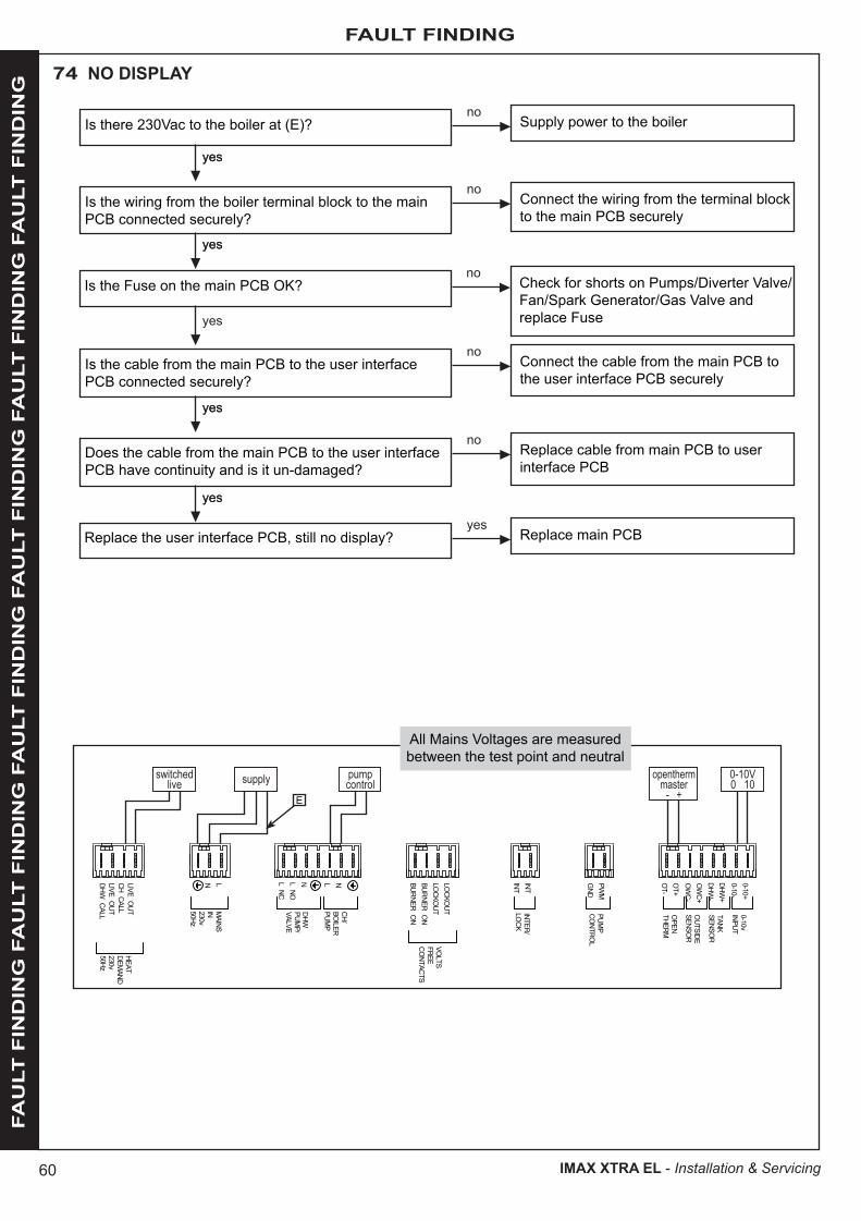
60
FAULT FINDING FA
ULT
FIN
DIN
G F
AU
LT
FIN
DIN
G F
AU
LT
FIN
DIN
G F
AU
LT
FIN
DIN
G F
AU
LT
FIN
DIN
G F
AU
LT
FIN
DIN
G
IMAX XTRA EL - Installation & Servicing
74 NO DISPLAY
Supply power to the boilerno
Is there 230Vac to the boiler at (E)?
yesyes
Connect the wiring from the terminal block to the main PCB securely
noIs the wiring from the boiler terminal block to the main PCB connected securely?
yesyes
Connect the cable from the main PCB to the user interface PCB securely
noIs the cable from the main PCB to the user interface PCB connected securely?
yesyes
yes
Replace cable from main PCB to user interface PCB
noDoes the cable from the main PCB to the user interface PCB have continuity and is it un-damaged?
yesyes
Replace main PCByes
Replace the user interface PCB, still no display?
0-10+0-10-DHW
+DHW
-OW
C+OW
C-OT+OT-
PWM
GND
INTINT
LOCKOUTLOCKOUTBURNER ONBURNER ON
NL NOL NC
NLLNLIVE OUTCH CALLLIVE OUTDHW
CALL
HEATDEM
AND230v50Hz
MAINS
IN230v
DHW
50Hz
PUMP/
VALVE
CH/BOILERPUM
P
VOLTSFREECONTACTS
INTER/LOCK
PUMP
CONTROL
0-10vINPUT
TANKSENSOR
OUTSIDESENSOR
OPENTHERM
switchedlive
pumpcontrol
0-10V0 10
openthermmaster
- +supply
All Mains Voltages are measured between the test point and neutral
E
Check for shorts on Pumps/Diverter Valve/Fan/Spark Generator/Gas Valve and replace Fuse
noIs the Fuse on the main PCB OK?
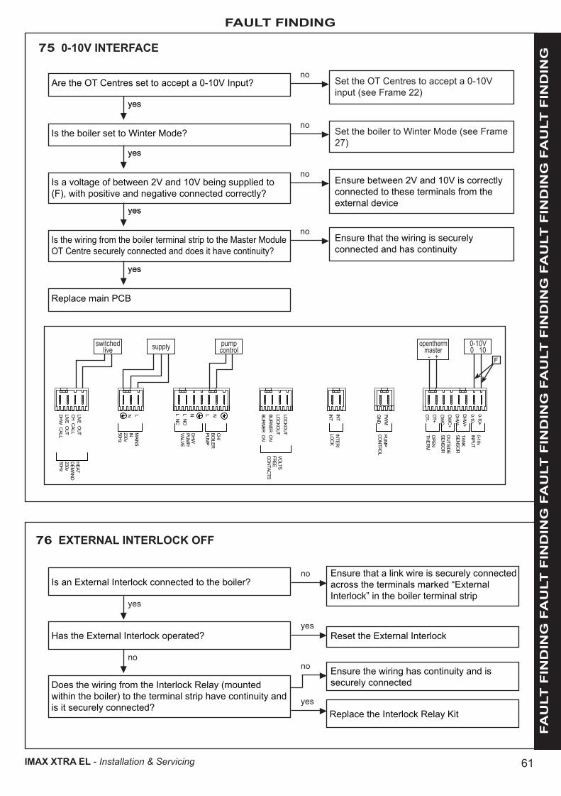
61
FAULT FINDING
FA
ULT
FIN
DIN
G F
AU
LT
FIN
DIN
G F
AU
LT
FIN
DIN
G F
AU
LT
FIN
DIN
G F
AU
LT
FIN
DIN
G F
AU
LT
FIN
DIN
G
IMAX XTRA EL - Installation & Servicing
0-10+0-10-DHW
+DHW
-OW
C+OW
C-OT+OT-
PWM
GND
INTINT
LOCKOUTLOCKOUTBURNER ONBURNER ON
NL NOL NC
NLLNLIVE OUTCH CALLLIVE OUTDHW
CALL
HEATDEM
AND230v50Hz
MAINS
IN230v
DHW
50Hz
PUMP/
VALVE
CH/BOILERPUM
P
VOLTSFREECONTACTS
INTER/LOCK
PUMP
CONTROL
0-10vINPUT
TANKSENSOR
OUTSIDESENSOR
OPENTHERM
switchedlive
pumpcontrol
0-10V0 10
openthermmaster
- +supply
75 0-10V INTERFACE
Set the OT Centres to accept a 0-10V input (see Frame 22)
noAre the OT Centres set to accept a 0-10V Input?
yesyes
Set the boiler to Winter Mode (see Frame 27)
noIs the boiler set to Winter Mode?
yesyes
Ensure between 2V and 10V is correctly connected to these terminals from the external device
noIs a voltage of between 2V and 10V being supplied to (F), with positive and negative connected correctly?
yesyes
Ensure that the wiring is securely connected and has continuity
noIs the wiring from the boiler terminal strip to the Master Module OT Centre securely connected and does it have continuity?
yesyes
Replace main PCB
F
76 EXTERNAL INTERLOCK OFF
Is an External Interlock connected to the boiler?
yes
Has the External Interlock operated?
no
Does the wiring from the Interlock Relay (mounted within the boiler) to the terminal strip have continuity and is it securely connected?
Replace the Interlock Relay Kit
Ensure that a link wire is securely connected across the terminals marked “External Interlock” in the boiler terminal strip
no
Reset the External Interlockyes
Ensure the wiring has continuity and is securely connected
no
yes

62
SPARE PARTS
IMAX XTRA EL - Installation & Servicing
When replacing any part on this appliance use only spare parts that you can be assured conform to the safety and performance specification that we require. Do not use reconditioned or copy parts that have not been clearly authorised by Ideal. Failure to do so could affect safety or performance of this appliance.
Comprehensive spares parts information and details of approved Ideal Parts Distributors are available on www.idealparts.com
Our Parts team are also available to help with your Ideal Spare Parts enquiries on 01482 498665.When calling, and to ensure we can provide you with the most accurate parts information, please ensure you have the following to hand;
- Boiler Model
- Boiler Serial Number
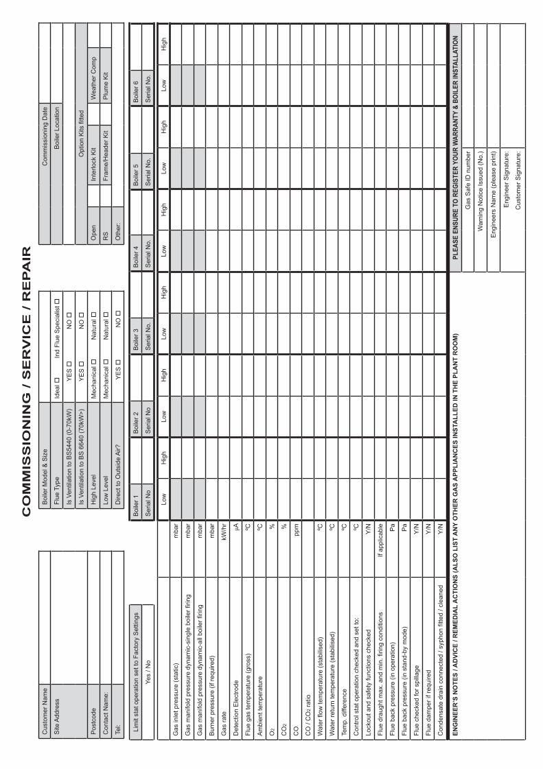
CO
MM
ISS
ION
ING
/ S
ER
VIC
E / R
EP
AIR
Cus
tom
er N
ame
Boi
ler M
odel
& S
ize
Com
mis
sion
ing
Dat
e
Site
Add
ress
Flue
Typ
eId
eal
Ind
Flue
Spe
cial
ist
Boi
ler L
ocat
ion
Is V
entil
atio
n to
BS
5440
(0-7
0kW
)Y
ES
NO
Is V
entil
atio
n to
BS
664
0 (7
0kW
>)Y
ES
NO
O
ptio
n K
its fi
tted
Pos
tcod
eH
igh
Leve
lM
echa
nica
l
Nat
ural
O
pen
Inte
rlock
Kit
Wea
ther
Com
p
Con
tact
Nam
e:Lo
w L
evel
Mec
hani
cal
Nat
ural
R
SFr
ame/
Hea
der K
itP
lum
e K
it
Tel:
Dire
ct to
Out
side
Air?
YE
S
NO
O
ther
:
Lim
it st
at o
pera
tion
set t
o Fa
ctor
y S
ettin
gsB
oile
r 1B
oile
r 2B
oile
r 3B
oile
r 4B
oile
r 5B
oile
r 6
Yes
/ No
Ser
ial N
oS
eria
l No
Ser
ial N
o.S
eria
l No.
Ser
ial N
o.S
eria
l No.
Low
Hig
hLo
wH
igh
Low
Hig
hLo
wH
igh
Low
Hig
hLo
wH
igh
Gas
inle
t pre
ssur
e (s
tatic
)m
bar
Gas
man
ifold
pre
ssur
e dy
nam
ic-s
ingl
e bo
iler fi
ring
mba
r
Gas
man
ifold
pre
ssur
e dy
nam
ic-a
ll bo
iler fi
ring
mba
r
Bur
ner p
ress
ure
(if re
quire
d)m
bar
Gas
rate
kW/h
r
Det
ectio
n E
lect
rode
µA
Flue
gas
tem
pera
ture
(gro
ss)
ºC
Am
bien
t tem
pera
ture
ºC
O2
%
CO
2%
CO
ppm
CO
/ C
O2
ratio
Wat
er fl
ow te
mpe
ratu
re (s
tabi
lised
)ºC
Wat
er re
turn
tem
pera
ture
(sta
bilis
ed)
ºC
Tem
p. d
iffer
ence
ºC
Con
trol s
tat o
pera
tion
chec
ked
and
set t
o:ºC
Lock
out a
nd s
afet
y fu
nctio
ns c
heck
edY
/N
Flue
dra
ught
max
. and
min
. firin
g co
nditi
ons
If ap
plic
able
Flue
bac
k pr
essu
re (i
n op
erat
ion)
Pa
Flue
bac
k pr
essu
re (i
n st
and-
by m
ode)
Pa
Flue
che
cked
for s
pilla
geY
/N
Flue
dam
per i
f req
uire
dY
/N
Con
dens
ate
drai
n co
nnec
ted
/ syp
hon
fitte
d / c
lean
edY
/N
ENG
INEE
R’S
NO
TES
/ AD
VIC
E / R
EMED
IAL
AC
TIO
NS
(ALS
O L
IST
AN
Y O
THER
GA
S A
PPLI
AN
CES
INST
ALL
ED IN
TH
E PL
AN
T R
OO
M)
PLEA
SE E
NSUR
E TO
REG
ISTE
R YO
UR W
ARRA
NTY
& BO
ILER
INST
ALLA
TION
Gas
Saf
e ID
num
ber
War
ning
Not
ice
Issu
ed (N
o.)
Eng
inee
rs N
ame
(ple
ase
prin
t)
Eng
inee
r Sig
natu
re:
Cus
tom
er S
igna
ture
:

64 IMAX XTRA EL - Installation & Servicing
SERVICE RECORDSERVICE RECORD
It is recommended that your heating system is serviced regularly and that the appropriate Service Interval Record is completed.Service ProviderBefore completing the appropriate Service Record below, please ensure you have carried out the service as described in the manufacturer’s instructions. Always use the manufacturer’s specified spare part when replacing controls.
SERVICE 01 Date:
Job No:
Engineer Name:
Company Name:
Telephone No:
Gas Safe Register No:
Gas Inlet Pressure (static) mbar
Gas Inlet Pressure (dynamic) - 1 Boiler mbar
Gas Inlet Pressure (dynamic) - all Boilers mbar
CO2 %
CO / CO2 Ratio %
Control Stat Setting ºC
Temp. Diff ºC
Burner Pressure (if applicable) mbar
Flue Gas Temp. ºC
Ambient Temp. ºC
Flue Draught (if applicable) mbar
Flue Back Pressure pa
Water/Other Safety inerlock proved Y/N
Comments:
Signature
SERVICE 03 Date:
Job No:
Engineer Name:
Company Name:
Telephone No:
Gas Safe Register No:
Gas Inlet Pressure (static) mbar
Gas Inlet Pressure (dynamic) - 1 Boiler mbar
Gas Inlet Pressure (dynamic) - all Boilers mbar
CO2 %
CO / CO2 Ratio %
Control Stat Setting ºC
Temp. Diff ºC
Burner Pressure (if applicable) mbar
Flue Gas Temp. ºC
Ambient Temp. ºC
Flue Draught (if applicable) mbar
Flue Back Pressure pa
Water/Other Safety inerlock proved Y/N
Comments:
Signature
SERVICE 02 Date:
Job No:
Engineer Name:
Company Name:
Telephone No:
Gas Safe Register No:
Gas Inlet Pressure (static) mbar
Gas Inlet Pressure (dynamic) - 1 Boiler mbar
Gas Inlet Pressure (dynamic) - all Boilers mbar
CO2 %
CO / CO2 Ratio %
Control Stat Setting ºC
Temp. Diff ºC
Burner Pressure (if applicable) mbar
Flue Gas Temp. ºC
Ambient Temp. ºC
Flue Draught (if applicable) mbar
Flue Back Pressure pa
Water/Other Safety inerlock proved Y/N
Comments:
Signature
SERVICE 04 Date:
Job No:
Engineer Name:
Company Name:
Telephone No:
Gas Safe Register No:
Gas Inlet Pressure (static) mbar
Gas Inlet Pressure (dynamic) - 1 Boiler mbar
Gas Inlet Pressure (dynamic) - all Boilers mbar
CO2 %
CO / CO2 Ratio %
Control Stat Setting ºC
Temp. Diff ºC
Burner Pressure (if applicable) mbar
Flue Gas Temp. ºC
Ambient Temp. ºC
Flue Draught (if applicable) mbar
Flue Back Pressure pa
Water/Other Safety inerlock proved Y/N
Comments:
Signature
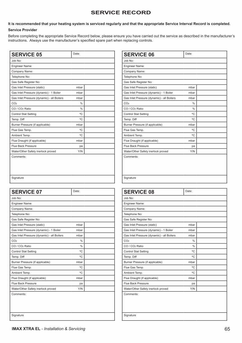
65IMAX XTRA EL - Installation & Servicing
SERVICE RECORDSERVICE RECORD
It is recommended that your heating system is serviced regularly and that the appropriate Service Interval Record is completed.Service ProviderBefore completing the appropriate Service Record below, please ensure you have carried out the service as described in the manufacturer’s instructions. Always use the manufacturer’s specified spare part when replacing controls.
SERVICE 05 Date:
Job No:
Engineer Name:
Company Name:
Telephone No:
Gas Safe Register No:
Gas Inlet Pressure (static) mbar
Gas Inlet Pressure (dynamic) - 1 Boiler mbar
Gas Inlet Pressure (dynamic) - all Boilers mbar
CO2 %
CO / CO2 Ratio %
Control Stat Setting ºC
Temp. Diff ºC
Burner Pressure (if applicable) mbar
Flue Gas Temp. ºC
Ambient Temp. ºC
Flue Draught (if applicable) mbar
Flue Back Pressure pa
Water/Other Safety inerlock proved Y/N
Comments:
Signature
SERVICE 07 Date:
Job No:
Engineer Name:
Company Name:
Telephone No:
Gas Safe Register No:
Gas Inlet Pressure (static) mbar
Gas Inlet Pressure (dynamic) - 1 Boiler mbar
Gas Inlet Pressure (dynamic) - all Boilers mbar
CO2 %
CO / CO2 Ratio %
Control Stat Setting ºC
Temp. Diff ºC
Burner Pressure (if applicable) mbar
Flue Gas Temp. ºC
Ambient Temp. ºC
Flue Draught (if applicable) mbar
Flue Back Pressure pa
Water/Other Safety inerlock proved Y/N
Comments:
Signature
SERVICE 06 Date:
Job No:
Engineer Name:
Company Name:
Telephone No:
Gas Safe Register No:
Gas Inlet Pressure (static) mbar
Gas Inlet Pressure (dynamic) - 1 Boiler mbar
Gas Inlet Pressure (dynamic) - all Boilers mbar
CO2 %
CO / CO2 Ratio %
Control Stat Setting ºC
Temp. Diff ºC
Burner Pressure (if applicable) mbar
Flue Gas Temp. ºC
Ambient Temp. ºC
Flue Draught (if applicable) mbar
Flue Back Pressure pa
Water/Other Safety inerlock proved Y/N
Comments:
Signature
SERVICE 08 Date:
Job No:
Engineer Name:
Company Name:
Telephone No:
Gas Safe Register No:
Gas Inlet Pressure (static) mbar
Gas Inlet Pressure (dynamic) - 1 Boiler mbar
Gas Inlet Pressure (dynamic) - all Boilers mbar
CO2 %
CO / CO2 Ratio %
Control Stat Setting ºC
Temp. Diff ºC
Burner Pressure (if applicable) mbar
Flue Gas Temp. ºC
Ambient Temp. ºC
Flue Draught (if applicable) mbar
Flue Back Pressure pa
Water/Other Safety inerlock proved Y/N
Comments:
Signature

Ideal is a trademark of Ideal Boilers. Registered Office Ideal Boilers Limited National Avenue, Hull, HU5 4JB. Telephone: 01482 492 251 Fax: 01482 448 858Registered in England no. 322137.
Technical Training
Ideal Boilers Limited pursues a policy of continuing improvement in the design and performance of its products. The right is therefore reserved to vary specification without notice.
The Ideal Boilers Technical Training Centre offers a series of first class training courses for domestic, commercial and industrial heating installers, engineers and system specifiers. For details of courses please ring: ................................ 01482 498 432
Ideal Installer/Technical Helpline: 01482 498 376www.idealcommercialboilers.com