Embed Size (px)
Citation preview

INSTALLATION ANDPROGRAMMING MANUAL
Section 0. Title and Document Version log. (This sheet)Section 1. Installation Manual.
Section 2. Introduction to Programming and System Overview.
Programming Reference:Section 3. General Options.Section 4. Times.Section 5. Areas.Section 6. Zone Inputs.Section 7. System Inputs.Section 8. Auxiliary Outputs.Section 9. Terminals.Section 10. Communications.Section 11. Users.
Section 12. Quick Programming. (Includes Programming record sheets)Section 13. Index.
Contents
© 2002. Inner Range Pty. Ltd. Part Number: 630047

p2 Section 0. Title. Version 1.02 CONCEPT IQ. Installation & Programming Manual.
SECTION TITLE CURRENT VERSION-AS AT 16 JAN 2002
0 Title and Document Version log (This sheet) 1.02
1 Installation Manual 1.01
2 Programming Introduction 1.01
3 General Options 1.01
4 Times 1.01
5 Areas 1.01
6 Zone Inputs 1.01
7 System Inputs 1.02
8 Auxiliary Outputs 1.01
9 Terminals 1.02
10 Communications 1.01
11 Users 1.01
12 System Planning & Programming record sheets 1.02
13 Index 1.02
Document Revisions
This table shows the current Version numbers of all documents in the “Concept IQ Installation and Programming Manual”.
This table can be used when checking the Website for updates. http://www.innerrange.com
When you replace any documents in this manual with new Versions, ensure that this table is updated or replaced with thelatest Version from the Website.
Inner Range Pty Ltd is proud of the reputation it has gained in the provision of high quality electronic products. Exhaustivefactory and field testing ensure that enhanced system programming features and additional hardware components operateas expected prior to their release to our customers. Extensive function testing is carried out on every Inner Range Conceptproduct prior to it leaving the factory.
It is our intention to completely satisfy the requirements of our customers. To that end, Inner Range Pty Ltd stands behindits products with confidence. A Two Year Warranty accompanies every Inner Range Concept product. Should anyConcept product fail to function as intended by the manufacturer within this period, it should be returned to the distributorand the fault or symptom detailed. Inner Range will, at its own discretion, repair or replace the product as soon as possible.
This Warranty does not cover product failures occurring wholly or in part as a result of misuse, malicious damage,accidental damage or acts of nature.
1) The manufacturer and/or it’s agents take no responsibility for any damage, financial loss or injury caused to anyequipment, property or persons resulting from the correct or incorrect use of the Concept IQ system and itsperipherals. The purchaser assumes all responsibility in the use of the Concept system and its peripherals.
2) Whilst every effort has been made to ensure the accuracy of this manual, Inner Range Pty Ltd assumes noresponsibility or liability for any errors or omissions. Due to ongoing development the contents of this manual issubject to change without notice. Check regularly with your supplier or the Website for updates.
Disclaimer
Warranty
CONCEPT IQ. Installation & Programming Manual.
Inst
all
p1
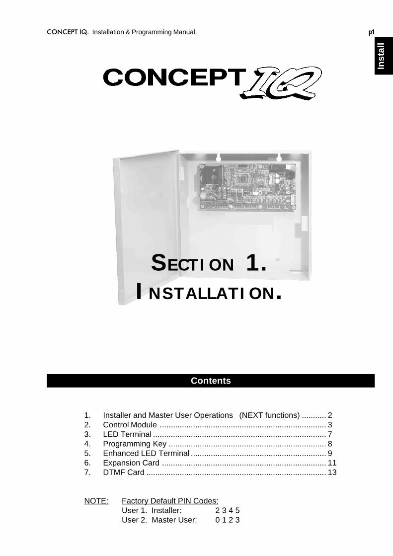
SECTION 1.INSTALLATION.
1. Installer and Master User Operations (NEXT functions) ........... 22. Control Module ........................................................................... 33. LED Terminal .............................................................................. 74. Programming Key ....................................................................... 85. Enhanced LED Terminal ............................................................. 96. Expansion Card .......................................................................... 117. DTMF Card ................................................................................. 13
NOTE: Factory Default PIN Codes:User 1. Installer: 2 3 4 5User 2. Master User: 0 1 2 3
Contents
Section 1. Installation. CONCEPT IQ. Installation & Programming Manual.p2
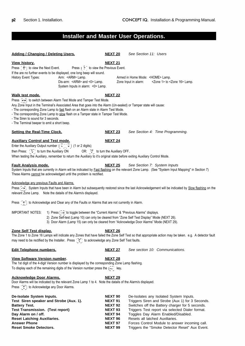
Adding / Changing / Deleting Users. NEXT 20 See Section 11: Users
View history. NEXT 21Press to view the Next Event. Press to view the Previous Event.If the are no further events to be displayed, one long beep will sound.History Event Types: Arm: <ARM> Lamp. Armed in Home Mode: <HOME> Lamp.
Dis-arm: <ARM> and <0> Lamp. Zone Input in alarm: <Zone 1> to <Zone 16> Lamp.System Inputs in alarm: <0> Lamp.
Walk test mode. NEXT 22Press to switch between Alarm Test Mode and Tamper Test Mode.Any Zone Input in the Terminal’s Associated Area that goes into the Alarm (Un-sealed) or Tamper state will cause:- The corresponding Zone Lamp to fast flash on an Alarm state in Alarm Test Mode.- The corresponding Zone Lamp to slow flash on a Tamper state in Tamper Test Mode.- The Siren to sound for 3 seconds.- The Terminal beeper to emit a short beep.
Setting the Real-Time Clock. NEXT 23 See Section 4: Time Programming.
Auxiliary Control and Test mode. NEXT 24Enter the Auxiliary Output number (1 or 2 digits);
then Press: to turn the Auxiliary ON OR: to turn the Auxiliary OFF..When testing the Auxiliary, remember to return the Auxiliary to it’s original state before exiting Auxiliary Control Mode.
Fault Analysis mode. NEXT 25 See Section 7: System InputsSystem Inputs that are currently in Alarm will be indicated by Fast flashing on the relevant Zone Lamp. (See "System Input Mapping" in Section 7)These Alarms cannot be acknowledged until the problem is rectified.
Acknowledge any previous Faults and Alarms.Press . System Inputs that have been in Alarm but subsequently restored since the last Acknowledgement will be indicated by Slow flashing on therelevant Zone Lamp. Note the datails of the Alarm/s displayed.
Press to Acknowledge and Clear any of the Faults or Alarms that are not currently in Alarm.
IMPORTANT NOTES: 1) Press to toggle between the “Current Alarms” & “Previous Alarms” displays.2) Zone Self-test (Lamp 10) can only be cleared from “Zone Self Test Display” Mode (NEXT 26).3) Door Alarm (Lamp 15) can only be cleared from “Acknowledge Door Alarms” Mode (NEXT 29).
Zone Self Test display. NEXT 26The Zone 1 to Zone 16 Lamps will indicate any Zones that have failed the Zone Self Test so that appropriate action may be taken. e.g. A detector faultmay need to be rectified by the Installer. Press to acknowledge any Zone Self Test faults.
Edit Telephone numbers. NEXT 27 See section 10: Communications.
View Software Version number. NEXT 28The 1st digit of the 4-digit Version number is displayed by the corresponding Zone Lamp flashing.To display each of the remaining digits of the Version number press the key..
Acknowledge Door Alarms. NEXT 29Door Alarms will be indicated by the relevant Zone Lamp 1 to 4. Note the datails of the Alarm/s displayed.Press to Acknowledge any Door Alarms.
De-Isolate System Inputs. NEXT 90 De-Isolates any Isolated System Inputs.Test Siren speaker and Strobe (Aux. 1). NEXT 91 Triggers Siren and Strobe (Aux 1) for 3 Seconds.Battery Test. NEXT 92 Switches off the Battery charger for 5 seconds.Test Transmission. (Test report) NEXT 93 Triggers Test report via selected Dialer format.Day Alarm on / off. NEXT 94 Toggles Day Alarm Enabled/Disabled.Reset Latching Auxiliaries. NEXT 96 Resets all latched Auxiliaries.Answer Phone NEXT 97 Forces Control Module to answer incoming call.Reset Smoke Detectors. NEXT 99 Triggers the “Smoke Detector Reset” Aux Event.
Installer and Master User Operations.
CONCEPT IQ. Installation & Programming Manual.
Inst
all
p3
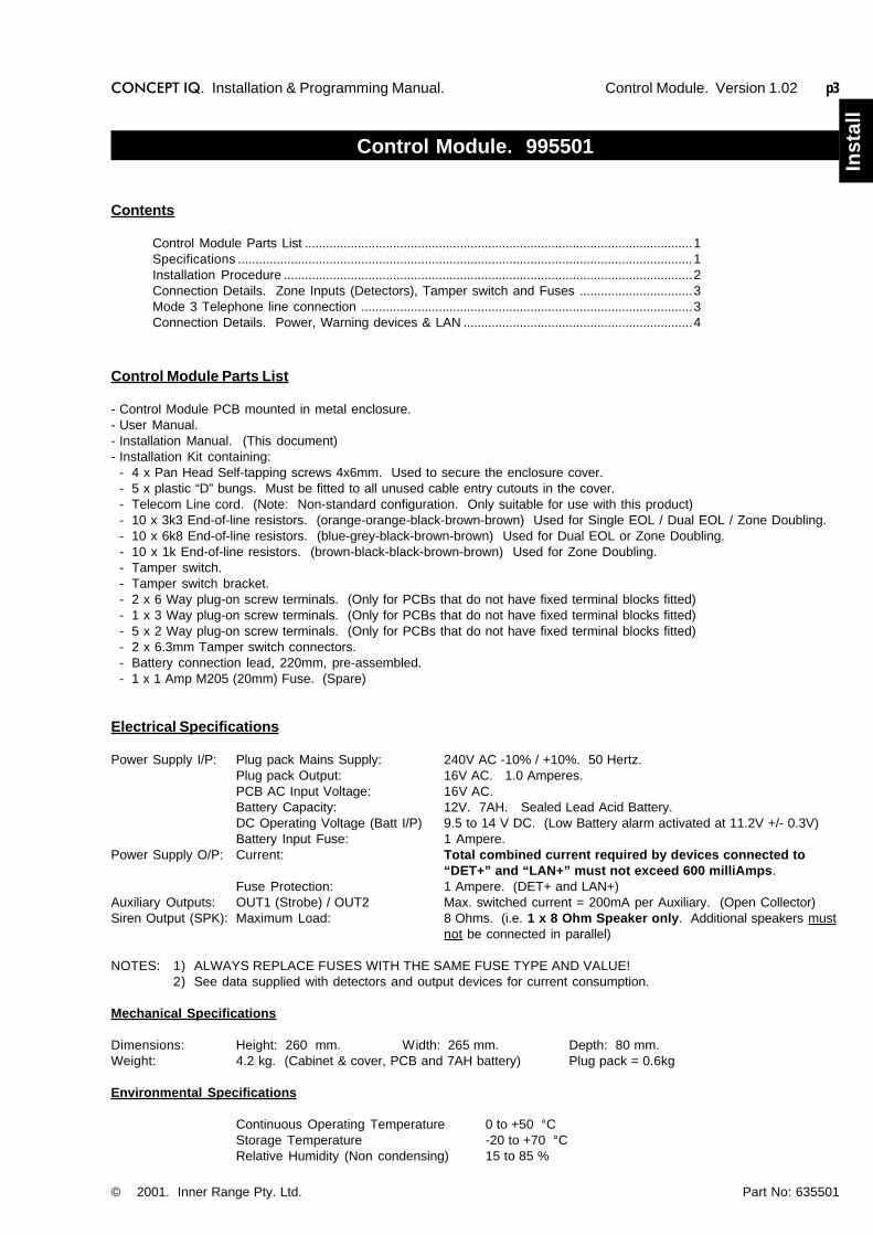
Control Module. 995501
Control Module Parts List
- Control Module PCB mounted in metal enclosure.- User Manual.- Installation Manual. (This document)- Installation Kit containing:
- 4 x Pan Head Self-tapping screws 4x6mm. Used to secure the enclosure cover.- 5 x plastic “D” bungs. Must be fitted to all unused cable entry cutouts in the cover.- Telecom Line cord. (Note: Non-standard configuration. Only suitable for use with this product)- 10 x 3k3 End-of-line resistors. (orange-orange-black-brown-brown) Used for Single EOL / Dual EOL / Zone Doubling.- 10 x 6k8 End-of-line resistors. (blue-grey-black-brown-brown) Used for Dual EOL or Zone Doubling.- 10 x 1k End-of-line resistors. (brown-black-black-brown-brown) Used for Zone Doubling.- Tamper switch.- Tamper switch bracket.- 2 x 6 Way plug-on screw terminals. (Only for PCBs that do not have fixed terminal blocks fitted)- 1 x 3 Way plug-on screw terminals. (Only for PCBs that do not have fixed terminal blocks fitted)- 5 x 2 Way plug-on screw terminals. (Only for PCBs that do not have fixed terminal blocks fitted)- 2 x 6.3mm Tamper switch connectors.- Battery connection lead, 220mm, pre-assembled.- 1 x 1 Amp M205 (20mm) Fuse. (Spare)
Electrical Specifications
Power Supply I/P: Plug pack Mains Supply: 240V AC -10% / +10%. 50 Hertz.Plug pack Output: 16V AC. 1.0 Amperes.PCB AC Input Voltage: 16V AC.Battery Capacity: 12V. 7AH. Sealed Lead Acid Battery.DC Operating Voltage (Batt I/P) 9.5 to 14 V DC. (Low Battery alarm activated at 11.2V +/- 0.3V)Battery Input Fuse: 1 Ampere.
Power Supply O/P: Current: Total combined current required by devices connected to“DET+” and “LAN+” must not exceed 600 milliAmps.
Fuse Protection: 1 Ampere. (DET+ and LAN+)Auxiliary Outputs: OUT1 (Strobe) / OUT2 Max. switched current = 200mA per Auxiliary. (Open Collector)Siren Output (SPK): Maximum Load: 8 Ohms. (i.e. 1 x 8 Ohm Speaker only. Additional speakers must
not be connected in parallel)
NOTES: 1) ALWAYS REPLACE FUSES WITH THE SAME FUSE TYPE AND VALUE!2) See data supplied with detectors and output devices for current consumption.
Mechanical Specifications
Dimensions: Height: 260 mm. Width: 265 mm. Depth: 80 mm.Weight: 4.2 kg. (Cabinet & cover, PCB and 7AH battery) Plug pack = 0.6kg
Environmental Specifications
Continuous Operating Temperature 0 to +50 °CStorage Temperature -20 to +70 °CRelative Humidity (Non condensing) 15 to 85 %
© 2001. Inner Range Pty. Ltd. Part No: 635501
Contents
Control Module Parts List ..............................................................................................................1Specifications .................................................................................................................................1Installation Procedure ....................................................................................................................2Connection Details. Zone Inputs (Detectors), Tamper switch and Fuses ................................3Mode 3 Telephone line connection ..............................................................................................3Connection Details. Power, Warning devices & LAN .................................................................4
Control Module. Version 1.02
Section 1. Installation. CONCEPT IQ. Installation & Programming Manual.p4
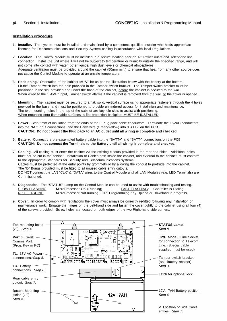
Installation Procedure
1. Installer. The system must be installed and maintained by a competent, qualified installer who holds appropriatelicences for Telecommunications and Security System cabling in accordance with local Regulations.
2. Location. The Control Module must be installed in a secure location near an AC Power outlet and Telephone lineconnection. Install the unit where it will not be subject to temperature or humidity outside the specified range, and willnot come into contact with water, other liquids, high dust levels or chemical atmospheres.Adequate ventilation must be provided around the cabinet (50mm min.) to ensure that heat from any other source doesnot cause the Control Module to operate at an unsafe temperature.
3. Positioning. Orientation of the cabinet MUST be as per the illustration below with the battery at the bottom.Fit the Tamper switch into the hole provided in the Tamper switch bracket. The Tamper switch bracket must bepositioned in the slot provided and under the base of the cabinet, before the cabinet is secured to the wall.When wired to the “TAMP” input, Tamper switch alarms if the cabinet is removed from the wall or the cover is opened.
4. Mounting. The cabinet must be secured to a flat, solid, vertical surface using appropriate fasteners through the 4 holesprovided in the base, and must be positioned to provide unhindered access for installation and maintenance.The two mounting holes in the top of the cabinet are keyhole slots to assist with positioning.When mounting onto flammable surfaces, a fire protection backplate MUST BE INSTALLED.
5. Power. Strip 5mm of insulation from the ends of the 3 Plug pack cable conductors. Terminate the 16VAC conductorsinto the “AC” Input connections, and the Earth wire (Green/Yellow) into “BATT-” on the PCB.CAUTION: Do not connect the Plug pack to an AC outlet until all wiring is complete and checked.
6. Battery. Connect the pre-assembled battery cable into the “BATT+” and “BATT-” connections on the PCB.CAUTION: Do not connect the Terminals to the Battery until all wiring is complete and checked.
7. Cabling. All cabling must enter the cabinet via the existing cutouts provided in the rear and sides. Additional holesmust not be cut in the cabinet. Installation of Cables both inside the cabinet, and external to the cabinet, must conformto the appropriate Standards for Security and Telecommunications systems.Cables must be protected at the entry points by grommets or by allowing the conduit to protrude into the cabinet.The “D” Bungs provided must be fitted to all unused cable entry cutouts.DO NOT connect the LAN “CLK” & “DATA” wires to the Control Module until all LAN Modules (e.g. LED Terminals) areCommissioned.
8. Diagnostics. The “STATUS” Lamp on the Control Module can be used to assist with troubleshooting and testing.SLOW FLASHING: MicroProcessor OK (Running) FAST FLASHING: Controller is Dialing.NOT FLASHING: MicroProcessor Not running, OR Programming Key Upload or Download in progress.
9. Cover. In order to comply with regulations the cover must always be correctly re-fitted following any installation ormaintenance work. Engage the hinges on the Left-hand side and fasten the cover tightly to the cabinet using all four (4)of the screws provided. Screw holes are located on both edges of the two Right-hand side corners.
STATUS Lamp.Step 8.
JP9. Mode 3 Line Socketfor connection to TelecomLine. (Special cablesupplied must be used)
Tamper switch bracket.(and Battery retainer)Step 3.
Latch for optional lock.
12V, 7AH Battery position.Step 6.
< Location of Side Cableentries. Step 7.
^ ^
<
>
V
Top mounting holes(x2). Step 4.
Port 0. SerialComms Port.(Prog. Key or PC)
T1. 16V AC Powerconnections. Step 5.
T3. Batteryconnections. Step 6.
Rear cable entrycutout. Step 7.
Bottom MountingHoles (x 2).Step 4.
CONCEPT IQ. Installation & Programming Manual.
Inst
all
p5
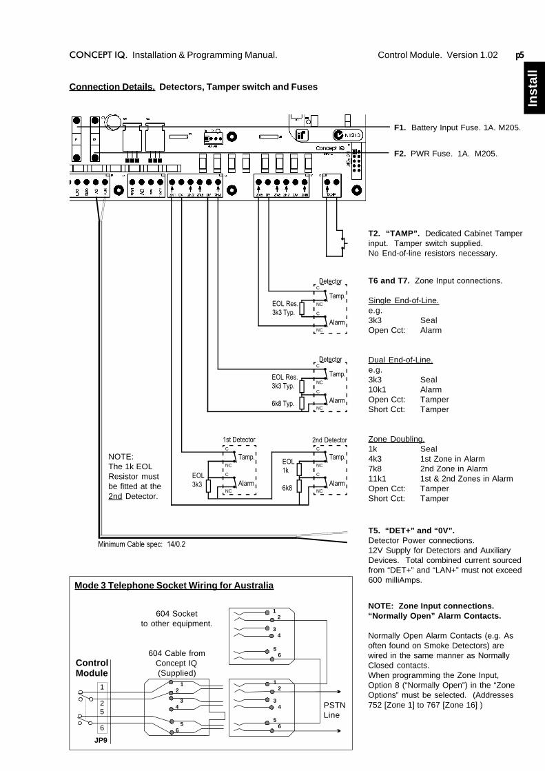
T2. “TAMP”. Dedicated Cabinet Tamperinput. Tamper switch supplied.No End-of-line resistors necessary.
T6 and T7. Zone Input connections.
Single End-of-Line.e.g.3k3 SealOpen Cct: Alarm
Dual End-of-Line.e.g.3k3 Seal10k1 AlarmOpen Cct: TamperShort Cct: Tamper
Zone Doubling.1k Seal4k3 1st Zone in Alarm7k8 2nd Zone in Alarm11k1 1st & 2nd Zones in AlarmOpen Cct: TamperShort Cct: Tamper
T5. “DET+” and “0V”.Detector Power connections.12V Supply for Detectors and AuxiliaryDevices. Total combined current sourcedfrom “DET+” and “LAN+” must not exceed600 milliAmps.
F1. Battery Input Fuse. 1A. M205.
Connection Details. Detectors, Tamper switch and Fuses
Minimum Cable spec: 14/0.2
Tamp.
Alarm
DetectorC
NC
C
NC
EOL Res.3k3 Typ.
Tamp.
Alarm
DetectorC
NC
C
NC
EOL Res.3k3 Typ.
6k8 Typ.
Tamp.
Alarm
2nd DetectorC
NC
C
NC
EOL1k
6k8
Tamp.
Alarm
1st DetectorC
NC
C
NC
EOL3k3
PSTNLine
604 Socketto other equipment.
604 Cable fromConcept IQ(Supplied)
Mode 3 Telephone Socket Wiring for Australia
F2. PWR Fuse. 1A. M205.
1 2
3 4
1 2
3 4
5 6
5 6
12
56
34
JP9
ControlModule
1
25
6
NOTE: Zone Input connections.“Normally Open” Alarm Contacts.
Normally Open Alarm Contacts (e.g. Asoften found on Smoke Detectors) arewired in the same manner as NormallyClosed contacts.When programming the Zone Input,Option 8 (“Normally Open”) in the “ZoneOptions” must be selected. (Addresses752 [Zone 1] to 767 [Zone 16] )
Control Module. Version 1.02
NOTE:The 1k EOLResistor mustbe fitted at the2nd Detector.
Section 1. Installation. CONCEPT IQ. Installation & Programming Manual.p6
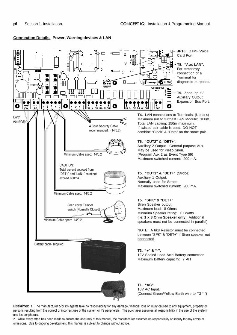
T1. “AC”.16V AC Input.(Connect Green/Yellow Earth wire to T3 “-”)
T4. LAN connections to Terminals. (Up to 4)Maximum run to furthest LAN Module: 100m.Total LAN cabling: 150m maximum.If twisted pair cable is used, DO NOTcombine “Clock” & “Data” on the same pair.
T9. Zone Input /Auxiliary OutputExpansion Bus Port.
T3. “+” & “-”.12V Sealed Lead Acid Battery connection.Maximum Battery capacity: 7 AH
T5. “SPK” & “DET+”Siren Speaker output.Maximum load: 8 OhmsMinimum Speaker rating: 10 Watts.(i.e. 1 x 8 Ohm Speaker only. Additionalspeakers must not be connected in parallel)
NOTE: A 6k8 Resistor must be connectedbetween “SPK” & “DET+” if Siren speaker notconnected.
T5. “OUT1” & “DET+” (Strobe)Auxiliary 1 Output.Normally used for Strobe.Maximum switched current: 200 mA.
T5. “OUT2” & “DET+”.Auxiliary 2 Output. General purpose Aux.May be used for Piezo Siren.(Program Aux 2 as Event Type 59)Maximum switched current: 200 mA.
Minimum Cable spec: 14/0.2
Minimum Cable spec: 14/0.2
Minimum Cable spec: 14/0.2
Battery cable supplied.
4 Core Security Cablerecommended. (14/0.2)
CAUTION:Total current sourced from“DET+” and “LAN+” must notexceed 600mA.
Connection Details. Power, Warning devices & LAN
T8. “Aux LAN”.For temporaryconnection of aTerminal fordiagnostic purposes.
Siren cover Tamperswitch (Normally Closed)
Disclaimer: 1. The manufacturer &/or it’s agents take no responsibility for any damage, financial loss or injury caused to any equipment, property orpersons resulting from the correct or incorrect use of the system or it’s peripherals. The purchaser assumes all responsibility in the use of the systemand it’s peripherals.2. While every effort has been made to ensure the accuracy of this manual, the manufacturer assumes no responsibility or liability for any errors oromissions. Due to ongoing development, this manual is subject to change without notice.
JP10. DTMF/VoiceCard Port.
Earth(Grn/Yell)

CONCEPT IQ. Installation & Programming Manual.
Inst
all
p7
Standard LED Terminal. 995500
© 2001. Inner Range Pty. Ltd. Part No: 635500
The LED Terminal is the main operator interface for the Concept IQ system.The Terminal provides status display of 16 Zone Inputs and 4 Areas along with indication of “Power”, “Fault”, “Home Mode”and “Armed” conditions. Audible button press feedback is provided and the built-in Beeper also provides indication ofAlarms, Entry/Exit warnings, Auto-Arm warning, User Operation OK and User Operation Unsuccessful.While the system can be programmed via Upload/Download software, the LED Terminal also provides the ability for theInstaller to program all system parameters.
LAN connections to the ControlModule T4 connector.
4 CoreSecurity Cablerecommended.(14/0.2)
INSTALLATION.
Mounting the Terminal.- The Terminal must be installed on a flat, vertical surface in an
appropriate location. Ensure that the display will be at, or slightlybelow eye level, for all Users.
- Remove the rear mounting plate from the back of the Terminal.- Cut suitable holes in the mounting surface for cable entry and the
fasteners. (The rear mounting plate can be used as a template)NOTE: The Terminal is also designed to be mounted on plasterboard/gyprock surfaces using a standard switch plate Mounting Clip. e.g.Clipsal 154 or HPM 712. (84mm mounting centres)
- The rear mounting plate can now be installed using appropriatefasteners through the holes provided. Remember to insert the LANcable and any other wiring through the cable entry cutout first.
- Connect the wiring into the Screw Terminal block T2.- Clip the Terminal onto the rear mounting plate by first locating the
tongue at the top of the Terminal into the slot provided by the rearmounting plate, then clip the bottom of the Terminal into place.
LAN connection. A maximum of 4 LAN Modules can be connected tothe system LAN. The LAN must be connected as follows:- Recommended cable is 4 core or 6 core security cable 14/0.20.
(NOT twisted pair. Twisted pair cable [e.g. Category 5] may be used,however, DO NOT combine “Clock” & “Data” on the same pair)
- Do not apply power to cable until all connections are made & checked.- Maximum cabling distance from the Control Module to the furthest
Module must not exceed 100 metres.- Maximum total LAN cabling in the system must not exceed 150 m.- DO NOT connect the “CLK” & “DATA” wires to the Control Module until
all LAN Modules (e.g. Terminals) are Commissioned. (See below)
ADDRESSING & COMMISSIONING (Read “LAN connection” first)
1. Enable Terminal Configuration Mode.Method 1: -Remove power from the Terminal.
-Hold down the <NEXT> and <HOME> keys.-Re-apply power to the Terminal.-Release the <NEXT> and <HOME> keys.
Method 2: -Hold down the <NEXT> and <HOME> keys.-Short the “RST” (Reset) link on the rear of the Terminal.-Release the <NEXT> and <HOME> keys.
2. Note the current Address setting. The current Address of the Terminal will be displayed via the Zone 1 to 4 Lamps.The Zone Lamp number that corresponds to the current Address will flash.
3. Select the new Terminal Address number.-Press the key that corresponds to the required Address (1 to 4) within 10 seconds, then press <ENTER>.-When the <ENTER> key is pressed, the Terminal will exit Terminal Configuration Mode.
4. Initialize the LAN. If a new Terminal is added to an existing system, once the Terminal is configured and connected tothe system LAN, the LAN must be initialized by Removing and Re-applying power to the Control Module.Remember to disconnect the battery also when removing power.
5. Area Assignment. Additional system programming allows Terminals to be configured for Single Area or Multi-AreaMode (Address 961), and an “Associated Area” to be defined for each Terminal (Addresses 952 to 955).
Standard LED Terminal. Version 1.01

Section 1. Installation. CONCEPT IQ. Installation & Programming Manual.p8
Programming Key. 995510
Programming Key Parts List
- Programming key.- Instruction Manual. (This document)
The Concept IQ Programming Key is a portable non-volatile memory device housed in a convenient “key tag”.The Programming Key connects directly to the Control Module Port 0 and allows the Installer to Upload the systemdatabase from the Control Module, or Download a system database to the Control Module via a simple key presssequence on the LED Terminal.
An indicator lamp is provided on the Programming key to monitor data transfer activity, and the LED Terminal providesaudible indication of Upload/Download Successful/Failed.
OPERATION.
Importing Data from the Programming Key.
This Mode allows the Installer to copy the programming contents of the Programming Key into the Control Module.
IMPORTANT NOTE: The new data will override the existing contents of the Control Module memory.
Connect the Programming Key to Serial Port 0 on the Control Module.
Select the Import Data Mode:Enter PIN; ... , then , then the Mode number; , .
The Lamp on the Programming Key will flash slowly to indicate data is being copied.The Terminal beeper will sound 3 short beeps if the operation was successful, or 1 long beep if unsuccessful.
Export Data to the Programming Key.
This Mode allows the Installer to copy the programming contents of the Control Module into the Programming Key.
IMPORTANT NOTE: The Control Module data will override the existing contents of the Programming Key.
Connect the Programming Key to Serial Port 0 on the Control Module.
Select the Export Data Mode:Enter PIN; ... , then , then the Mode number; , .
The Lamp on the Programming Key will flash quickly to indicate data is being copied.The Terminal beeper will sound 3 short beeps if the operation was successful, or 1 long beep if unsuccessful.
© 2001. Inner Range Pty. Ltd. Part No: 635510
Programming Keyconnected to Port 0.
Control Module
Version 1.00

CONCEPT IQ. Installation & Programming Manual.
Inst
all
p9
Enhanced LED Terminal. 995500EN
© 2001. Inner Range Pty. Ltd. Part No: 635500EN
The Enhanced LED Terminal is a versatile operator interface for the Concept IQ system providing standard LED Terminalfunctions along with an interface for Door Access Control. The Terminal provides status display of a single “Associated”Area and up to 16 Zone Inputs along with indication of “Power”, “Fault”, “Home Mode” and “Armed” conditions.Audible button press feedback is provided and the built-in Beeper also provides indication of Alarms, Entry/Exit warnings,Auto-Arm warning, User Operation OK and User Operation Unsuccessful.While the system can be programmed via Upload/Download software, the Terminal also provides the ability for the Installerto program all system parameters.
In addtion to these standard functions, the Enhanced Terminal also provides:-Single low power open-collector Door Unlock Output. (Programmable un-lock time; 0 to 60 seconds)-Two multi purpose inputs configurable as Wiegand Reader Data inputs and REX / Door Sealed.
INSTALLATION. Connection diagrams provided on the next page.
Mounting the Terminal.- IMPORTANT: Enhanced Terminals must be installed on the inside (secure side) of the Door to be controlled.- The Terminal must be installed on a flat, vertical surface in an appropriate location. Ensure that the display will be at, or
slightly below eye level, for all Users.- Remove the rear mounting plate from the back of the Terminal.- Cut suitable holes in the mounting surface for cable entry and the fasteners. (The rear mounting plate can be used as a
template)NOTE: The Terminal is also designed to be mounted on plasterboard/gyprock surfaces using a standard switch plateMounting Clip. e.g. Clipsal 154 or HPM 712.
- The rear mounting plate can now be installed using appropriate fasteners through the holes provided. Remember toinsert the LAN cable and other wiring through the cable entry cutout first.
- Connect the wiring into the Screw Terminal block T2.- Clip the Terminal onto the rear mounting plate by first locating the tongue at the top of the Terminal into the slot pro-
vided by the rear mounting plate, then clip the bottom of the Terminal into place.
LAN connection. A maximum of 4 LAN Modules can be connected to the system LAN.- Recommended cable is 4 core or 6 core security cable 14/0.20. (NOT twisted pair. Twisted pair cable [e.g. Category 5]
may be used, however, DO NOT combine “Clock” & “Data” on the same pair.)- Do not apply power to cable until all connections are made and checked.- Maximum cabling distance from the Control Module to the furthest Module must not exceed 100 metres.- Maximum total LAN cabling in the system must not exceed 150 metres.- DO NOT connect the “CLK” & “DATA” wires to the Control Module until all LAN Modules (e.g. Terminals) are
Commissioned. (See next page)
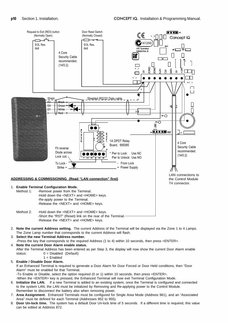
Wiegand Reader connection. Note: Supports 12V Reader power supply only. (No 5V supply option)- The Reader “+”, “-”, “D1” & “D0” wires must be connected to “+LAN”, “0V”, “Zone1” & “Zone2” on the Terminal using
Shielded RS232 Data cable. e.g. Tycab DMC6702, Electra EAS7206, Belden 9536, Alpha 1296C, etc.DO NOT use Twisted pair cable or Security cable under any circumstances.NOTE: Check that there is sufficient current still available from the LAN power to supply the Reader. If not, a separatepower supply must be used for the Reader power.
- Diodes must be inserted in series with each of the D0 and D1 connections. Cathode to Reader.Ensure that appropriate insulating sleeve is fitted over the Diodes and solder connections.
- Maximum cabling distance from the Reader to the Terminal must not exceed 80 metres.
Door Reed switch and Request to Exit button (REX) connections.- The “Normally Open” Request to Exit (REX) button (if used) is connected between the “Zone 1” Input and “0V”. A 6k8
Resistor must be connected in series with the button.- The “Normally Closed” Reed switch (if used) is connected between the “Zone 2” Input and “0V”. A 6k8 Resistor must be
connected in series with the Reed switch.
Lock Relay connection.- The Lock power must be switched via a Relay to provide isolation from the Terminal circuits.
e.g. 995085 -1A DPDT Relay Board, or 995083S -2x10A Relay Board.- The Relay control input is connected to “+” and “AUX1” on the Terminal.- The power to the lock must be wired from a separate lock power supply, through the appropriate Relay contacts, and
must not make any connection to the Terminal wiring.
Enhanced LED Terminal. Version 1.02
Section 1. Installation. CONCEPT IQ. Installation & Programming Manual.p10
LAN connections tothe Control ModuleT4 connector.
4 CoreSecurity Cablerecommended.(14/0.2)
ADDRESSING & COMMISSIONING (Read “LAN connection” first)
1. Enable Terminal Configuration Mode.Method 1: -Remove power from the Terminal.
-Hold down the <NEXT> and <HOME> keys.-Re-apply power to the Terminal.-Release the <NEXT> and <HOME> keys.
Method 2: -Hold down the <NEXT> and <HOME> keys.-Short the “RST” (Reset) link on the rear of the Terminal.-Release the <NEXT> and <HOME> keys.
2. Note the current Address setting. The current Address of the Terminal will be displayed via the Zone 1 to 4 Lamps.The Zone Lamp number that corresponds to the current Address will flash.
3. Select the new Terminal Address number.-Press the key that corresponds to the required Address (1 to 4) within 10 seconds, then press <ENTER>.
4. Note the current Door Alarm enable status.After the Terminal Address has been entered as per Step 3, the display will now show the current Door Alarm enablestatus: 0 = Disabled (Default)
1 = Enabled5. Enable / Disable Door Alarm.
If an Enhanced Terminal is required to generate a Door Alarm for Door Forced or Door Held conditions, then “DoorAlarm” must be enabled for that Terminal.-To Enable or Disable, select the option required (0 or 1) within 10 seconds, then press <ENTER>.-When the <ENTER> key is pressed, the Enhanced Terminal will now exit Terminal Configuration Mode.
6. Initialize the LAN. If a new Terminal is added to an existing system, once the Terminal is configured and connectedto the system LAN, the LAN must be initialized by Removing and Re-applying power to the Control Module.Remember to disconnect the battery also when removing power.
7. Area Assignment. Enhanced Terminals must be configured for Single Area Mode (Address 961), and an “AssociatedArea” must be defined for each Terminal (Addresses 952 to 955).
8. Door Un-lock time. The system has a default Door Un-lock time of 5 seconds. If a different time is required, this valuecan be edited at Address 872.
Request to Exit (REX) button(Normally Open)
EOL Res.6k8
Door Reed Switch(Normally Closed)
EOL Res.6k8
Shield0V BlackD0 GreenD1 White+ Red
To Lock -Strike +
- From Lock+ Power Supply
*
1A DPDT RelayBoard. 995085
* Pwr to Lock: Use NCPwr to Unlock: Use NO
4 CoreSecurity Cablerecommended.(14/0.2)
Shielded RS232 Data cable.
Fit reverseDiode acrossLock coil.
CONCEPT IQ. Installation & Programming Manual.
Inst
all
p11
Expansion Card. 995503 / 995504
© 2001. Inner Range Pty. Ltd. Part No: 635504
Expansion Card Parts List
- Zone/Auxiliary Expansion Card.- Installation Manual. (This document)- Installation Kit containing:
- 3 x 20mm Brass PCB standoff.- 1 x 20mm Threaded plastic PCB standoff.- 1 x Pan Head M3x6mm screw.- 2 x 6 Way plug-on screw terminals.- 4 x 2 Way plug-on screw terminals.- 10 x 3k3 End-of-line resistors. 8 x Zone Inputs, 2 x Spare. (orange-orange-black-brown-brown)- 10 x 6k8 End-of-line resistors. 8 x Zone Inputs, 2 x Spare. (blue-grey-black-brown-brown)
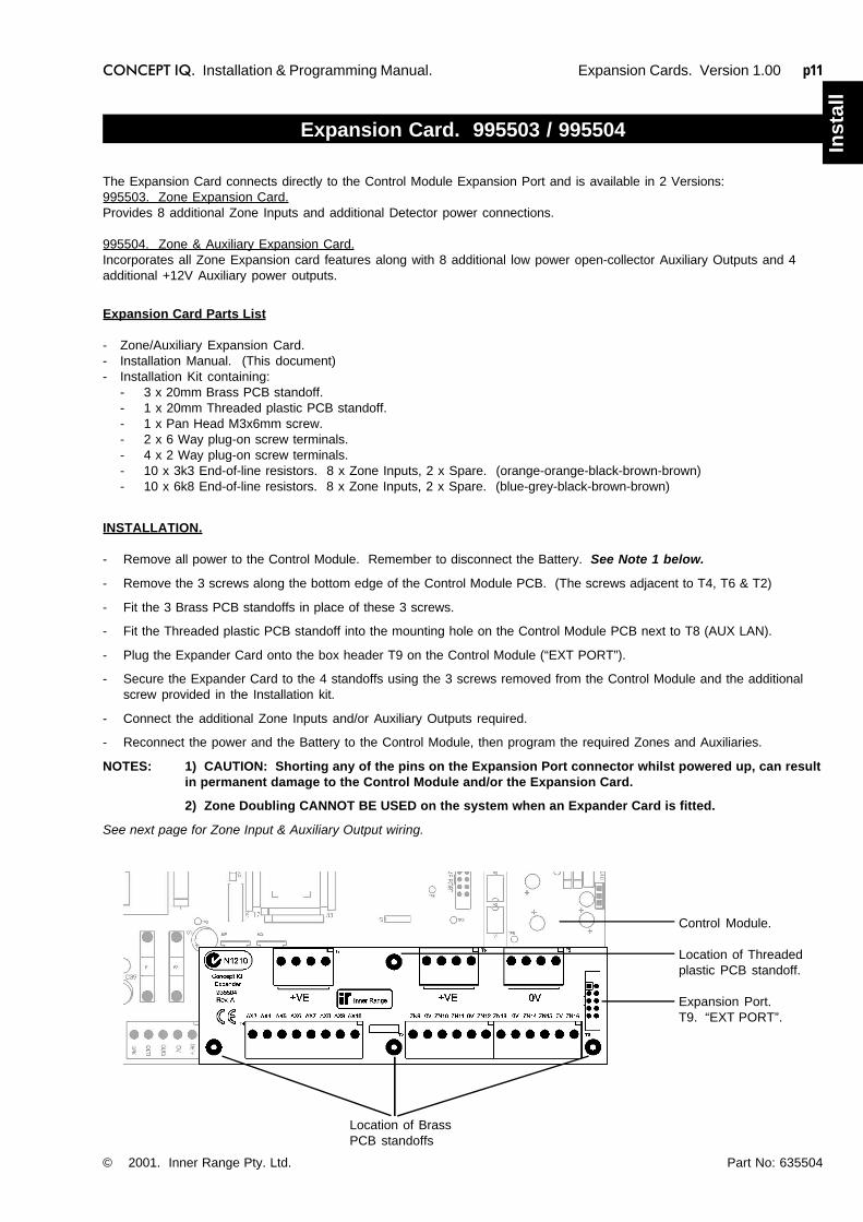
The Expansion Card connects directly to the Control Module Expansion Port and is available in 2 Versions:995503. Zone Expansion Card.Provides 8 additional Zone Inputs and additional Detector power connections.
995504. Zone & Auxiliary Expansion Card.Incorporates all Zone Expansion card features along with 8 additional low power open-collector Auxiliary Outputs and 4additional +12V Auxiliary power outputs.
INSTALLATION.
- Remove all power to the Control Module. Remember to disconnect the Battery. See Note 1 below.
- Remove the 3 screws along the bottom edge of the Control Module PCB. (The screws adjacent to T4, T6 & T2)
- Fit the 3 Brass PCB standoffs in place of these 3 screws.
- Fit the Threaded plastic PCB standoff into the mounting hole on the Control Module PCB next to T8 (AUX LAN).
- Plug the Expander Card onto the box header T9 on the Control Module (“EXT PORT”).
- Secure the Expander Card to the 4 standoffs using the 3 screws removed from the Control Module and the additionalscrew provided in the Installation kit.
- Connect the additional Zone Inputs and/or Auxiliary Outputs required.
- Reconnect the power and the Battery to the Control Module, then program the required Zones and Auxiliaries.
NOTES: 1) CAUTION: Shorting any of the pins on the Expansion Port connector whilst powered up, can resultin permanent damage to the Control Module and/or the Expansion Card.
2) Zone Doubling CANNOT BE USED on the system when an Expander Card is fitted.
See next page for Zone Input & Auxiliary Output wiring.
Location of BrassPCB standoffs
Control Module.
Location of Threadedplastic PCB standoff.
Expansion Port.T9. “EXT PORT”.
Expansion Cards. Version 1.00
Section 1. Installation. CONCEPT IQ. Installation & Programming Manual.p12
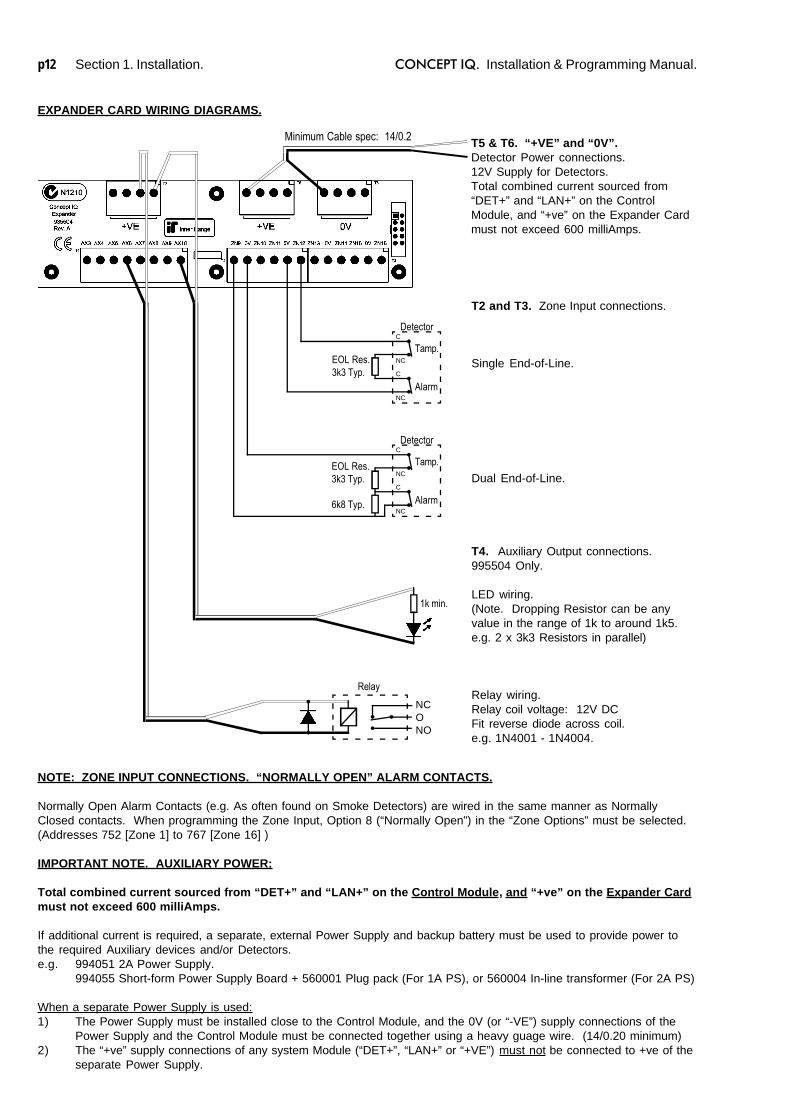
T2 and T3. Zone Input connections.
Single End-of-Line.
Dual End-of-Line.
T5 & T6. “+VE” and “0V”.Detector Power connections.12V Supply for Detectors.Total combined current sourced from“DET+” and “LAN+” on the ControlModule, and “+ve” on the Expander Cardmust not exceed 600 milliAmps.
Minimum Cable spec: 14/0.2
Tamp.
Alarm
DetectorC
NC
C
NC
EOL Res.3k3 Typ.
Tamp.
Alarm
DetectorC
NC
C
NC
EOL Res.3k3 Typ.
6k8 Typ.
T4. Auxiliary Output connections.995504 Only.
LED wiring.(Note. Dropping Resistor can be anyvalue in the range of 1k to around 1k5.e.g. 2 x 3k3 Resistors in parallel)
Relay wiring.Relay coil voltage: 12V DCFit reverse diode across coil.e.g. 1N4001 - 1N4004.
1k min.
Relay
NCONO
EXPANDER CARD WIRING DIAGRAMS.
IMPORTANT NOTE. AUXILIARY POWER:
Total combined current sourced from “DET+” and “LAN+” on the Control Module, and “+ve” on the Expander Cardmust not exceed 600 milliAmps.
If additional current is required, a separate, external Power Supply and backup battery must be used to provide power tothe required Auxiliary devices and/or Detectors.e.g. 994051 2A Power Supply.
994055 Short-form Power Supply Board + 560001 Plug pack (For 1A PS), or 560004 In-line transformer (For 2A PS)
When a separate Power Supply is used:1) The Power Supply must be installed close to the Control Module, and the 0V (or “-VE”) supply connections of the
Power Supply and the Control Module must be connected together using a heavy guage wire. (14/0.20 minimum)2) The “+ve” supply connections of any system Module (“DET+”, “LAN+” or “+VE”) must not be connected to +ve of the
separate Power Supply.
NOTE: ZONE INPUT CONNECTIONS. “NORMALLY OPEN” ALARM CONTACTS.
Normally Open Alarm Contacts (e.g. As often found on Smoke Detectors) are wired in the same manner as NormallyClosed contacts. When programming the Zone Input, Option 8 (“Normally Open”) in the “Zone Options” must be selected.(Addresses 752 [Zone 1] to 767 [Zone 16] )
CONCEPT IQ. Installation & Programming Manual.
Inst
all
p13
DTMF Card. 995505
© 2001. Inner Range Pty. Ltd. Part No: 635505
INSTALLATION.
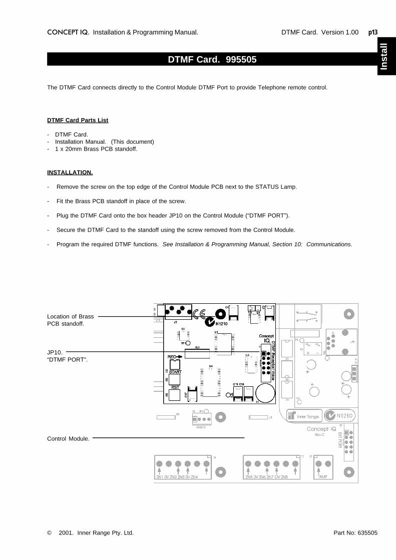
- Remove the screw on the top edge of the Control Module PCB next to the STATUS Lamp.
- Fit the Brass PCB standoff in place of the screw.
- Plug the DTMF Card onto the box header JP10 on the Control Module (“DTMF PORT”).
- Secure the DTMF Card to the standoff using the screw removed from the Control Module.
- Program the required DTMF functions. See Installation & Programming Manual, Section 10: Communications.
DTMF Card Parts List
- DTMF Card.- Installation Manual. (This document)- 1 x 20mm Brass PCB standoff.
The DTMF Card connects directly to the Control Module DTMF Port to provide Telephone remote control.
Location of BrassPCB standoff.
JP10.“DTMF PORT”.
Control Module.
DTMF Card. Version 1.00

Section 1. Installation. CONCEPT IQ. Installation & Programming Manual.p14
This page intentionally left blank.

Section 2. Intro. Version 1.01 p1CONCEPT IQ. Installation & Programming Manual.
Intr
o
SECTION 2.INTRODUCTION TO PROGRAMMING.
1. Introduction1.1 System Overview .............................................................................................. 21.2 Types of Users .................................................................................................. 31.3 Default Users .................................................................................................... 3
2. The LED Terminal2.1 Key Functions ................................................................................................... 42.2 Beeper Indications ............................................................................................. 42.3 Lamp Indications ............................................................................................... 5
3 Installer Modes3.1 Overview........................................................................................................... 63.2 Accessing the Installer Modes ........................................................................... 63.3 Mode 01. Programming Mode ........................................................................... 73.4 Mode 02. Defaulting Mode ................................................................................ 73.5 Factory Default Database settings .................................................................... 83.6 Mode 03. Import Data from Programming Key .................................................. 93.7 Mode 04. Export Data to Programming Key ...................................................... 93.8 Mode 05. Terminal Area Programming .............................................................. 9
4 Programming Techniques4.1 The System Database ....................................................................................... 104.2 Selecting and Programming the Data ................................................................. 104.3 Example of Programming .................................................................................. 11
5 Types of Data5.1 Overview........................................................................................................... 125.2 “Value” Data ...................................................................................................... 125.3 “Options” Data ................................................................................................... 13
6 Recommended Programming Sequence .................................................................. 14
Contents

p2 Section 2. Intro. Version 1.01 CONCEPT IQ. Installation & Programming Manual.
1. Introduction
1.1 SYSTEM OVERVIEW
The Concept IQ is an affordable, simple to use security system targeted at the domestic and small commercialmarkets. The system has been designed for ease of use by the Installer and the End User.
System Hardware
The basic Control Module has the following hardware dimensions:• Zones: 8 standard Zone Inputs or 16 doubled Zone Inputs.• Auxiliaries: Total of 3. 1 Siren speaker / 1 Strobe / 1 General purpose.• Serial Communications Port: RS232.• External Device Bus.• System LAN: Provides connectivity for up to 4 LAN Devices.• IO Expansion Bus.• Separate Tamper Input.
A variety of Peripheral devices can be connected directly to the Control Module:• Programming Key.• Plug-on Expansion Card options. 8 additional Auxiliary outputs and/or 8 additional Zone Inputs.• DTMF communications Card.• DTMF + Voice communications Card.• Serial Adapter Cable for connection to PC.
The System LAN supports the following LAN Modules:• Standard 16 Zone / 4 Area LED Terminal.• Enhanced 16 Zone / 4 Area LED Terminal incorporating Input for a Wiegand Reader
and Input/Output facilities for access control functions.• RF Terminal that adds 2 key or 4 key radio remote functionality.
Functional Description
Zone Inputs. Zone Inputs are individually programmed to define how they are to be processed. An appropriate“Zone Type” is chosen and additional options relating to; Alarm Processing, Reporting, Siren,Pulse counting, Testing, and type of Input Device can also be defined.Global Zone options also allow system-wide parameters to be set for Pulse Counting, End-Of-LineResistor values and Zone Self Testing.
System Inputs. 20 System Inputs are also available for monitoring Faults and System Alarms such as; PowerProblems, Cabinet & Siren Tampers, Communication Problems, LAN & Battery Fuses, Zone Self-test Status, Keypad Emergency Alarms (Panic, Fire, Medical & Duress) and Access Controlviolations. The Installer enables the Siren and Reporting options for each System Input required.Automatic Battery Testing is available and triggers the Low Battery alarm if the test fails.
Areas. The system can be configured in Single Area or Multi Area Mode according to the siterequirements. Up to 4 Areas are available and Zone Inputs can be assigned to one or more Areas.Each Area can be armed in “AWAY” or “HOME” modes.Each LED Terminal can be configured for Multi-Area mode or assigned to a Single Area.
Siren. The Siren Speaker output supports a standard 8 Ohm Horn speaker and can generate 4 differentsiren tones for Burglary, Fire, Medical & Panic alarms. The Siren time is programmable and anySystem Input Alarms that are programmed to activate the Siren are differentiated from Zone InputAlarms by a choice of 3 Siren tone-burst options.
Auxiliaries. Auxiliary outputs are extremely flexible thanks to a range of versatile programming options forSecurity, Access control and Building/Home automation. A choice of over 50 “Auxiliary Types”provides for Auxiliaries to; Annunciate different types of alarms, Indicate (mimic) individual Area orZone status, Indicate Entry, Exit, Auto-Arm & Zone Bypass conditions, Follow TimeZones, etc.For each individual Auxiliary the output logic and On/Off actions can be tailored including anoptional timer that can be programmed in Minutes or Seconds.
Communications.The system offers “Contact ID” or “Domestic” dialing options. For a higher level of Dialer integrity aSecondary telephone number can be programmed, Telephone line monitoring is provided and themaximum number of dial attempts can be specified. A “Comms Fail” alarm is activated if the line is
Section 2. Intro. Version 1.01 p3CONCEPT IQ. Installation & Programming Manual.
Intr
o
1.2 TYPES OF USERS
1.3 DEFAULT USERS:
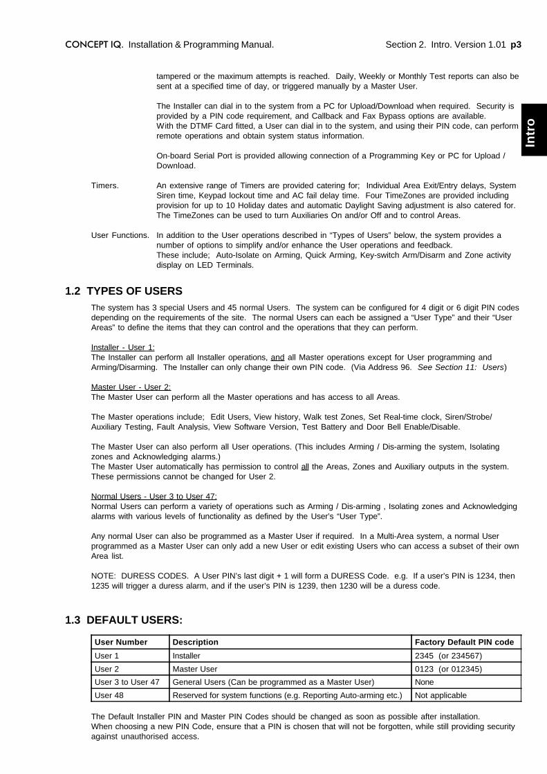
The system has 3 special Users and 45 normal Users. The system can be configured for 4 digit or 6 digit PIN codesdepending on the requirements of the site. The normal Users can each be assigned a “User Type” and their “UserAreas” to define the items that they can control and the operations that they can perform.
Installer - User 1:The Installer can perform all Installer operations, and all Master operations except for User programming andArming/Disarming. The Installer can only change their own PIN code. (Via Address 96. See Section 11: Users)
Master User - User 2:The Master User can perform all the Master operations and has access to all Areas.
The Master operations include; Edit Users, View history, Walk test Zones, Set Real-time clock, Siren/Strobe/Auxiliary Testing, Fault Analysis, View Software Version, Test Battery and Door Bell Enable/Disable.
The Master User can also perform all User operations. (This includes Arming / Dis-arming the system, Isolatingzones and Acknowledging alarms.)The Master User automatically has permission to control all the Areas, Zones and Auxiliary outputs in the system.These permissions cannot be changed for User 2.
Normal Users - User 3 to User 47:Normal Users can perform a variety of operations such as Arming / Dis-arming , Isolating zones and Acknowledgingalarms with various levels of functionality as defined by the User’s “User Type”.
Any normal User can also be programmed as a Master User if required. In a Multi-Area system, a normal Userprogrammed as a Master User can only add a new User or edit existing Users who can access a subset of their ownArea list.
NOTE: DURESS CODES. A User PIN’s last digit + 1 will form a DURESS Code. e.g. If a user’s PIN is 1234, then1235 will trigger a duress alarm, and if the user’s PIN is 1239, then 1230 will be a duress code.
tampered or the maximum attempts is reached. Daily, Weekly or Monthly Test reports can also besent at a specified time of day, or triggered manually by a Master User.
The Installer can dial in to the system from a PC for Upload/Download when required. Security isprovided by a PIN code requirement, and Callback and Fax Bypass options are available.With the DTMF Card fitted, a User can dial in to the system, and using their PIN code, can performremote operations and obtain system status information.
On-board Serial Port is provided allowing connection of a Programming Key or PC for Upload /Download.
Timers. An extensive range of Timers are provided catering for; Individual Area Exit/Entry delays, SystemSiren time, Keypad lockout time and AC fail delay time. Four TimeZones are provided includingprovision for up to 10 Holiday dates and automatic Daylight Saving adjustment is also catered for.The TimeZones can be used to turn Auxiliaries On and/or Off and to control Areas.
User Functions. In addition to the User operations described in “Types of Users” below, the system provides anumber of options to simplify and/or enhance the User operations and feedback.These include; Auto-Isolate on Arming, Quick Arming, Key-switch Arm/Disarm and Zone activitydisplay on LED Terminals.
The Default Installer PIN and Master PIN Codes should be changed as soon as possible after installation.When choosing a new PIN Code, ensure that a PIN is chosen that will not be forgotten, while still providing securityagainst unauthorised access.
User Number Description Factory Default PIN code
User 1 Installer 2345 (or 234567)
User 2 Master User 0123 (or 012345)
User 3 to User 47 General Users (Can be programmed as a Master User) None
User 48 Reserved for system functions (e.g. Reporting Auto-arming etc.) Not applicable
p4 Section 2. Intro. Version 1.01 CONCEPT IQ. Installation & Programming Manual.
2. The LED Terminal
2 or 3 Short Beeps: A User, Master or Installer function was successful.1 Long Beep: A User, Master or Installer function has been unsuccessful.
When a wrong key is pressed, or an incorrect value/option is selected, the beeper toneswill sound at a lower pitch until a correct operation is successfully performed.
Continuous Short Beeps*: Entry Delay Timer, Exit Delay Timer or Auto-arm Warning.
*NOTE:Single Area systems. All Terminals will beep in response to Exit delay, Entry delay or Auto-arm warnings.Multi-Area systems. Only Terminals associated with a particular Area will beep in response to that Area’s
warning functions. IMPORTANT NOTE: Terminals not associated with an Area will onlybeep on Area 1 warning functions.
2.2 BEEPER INDICATIONS.
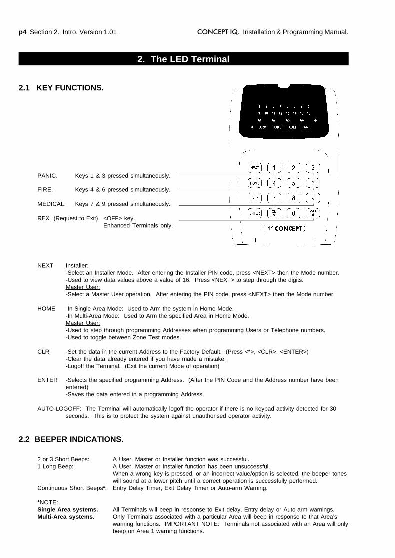
PANIC. Keys 1 & 3 pressed simultaneously.
FIRE. Keys 4 & 6 pressed simultaneously.
MEDICAL. Keys 7 & 9 pressed simultaneously.
REX (Request to Exit) <OFF> key.Enhanced Terminals only.
2.1 KEY FUNCTIONS.
NEXT Installer:-Select an Installer Mode. After entering the Installer PIN code, press <NEXT> then the Mode number.-Used to view data values above a value of 16. Press <NEXT> to step through the digits.Master User:-Select a Master User operation. After entering the PIN code, press <NEXT> then the Mode number.
HOME -In Single Area Mode: Used to Arm the system in Home Mode.-In Multi-Area Mode: Used to Arm the specified Area in Home Mode.Master User:-Used to step through programming Addresses when programming Users or Telephone numbers.-Used to toggle between Zone Test modes.
CLR -Set the data in the current Address to the Factory Default. (Press <*>, <CLR>, <ENTER>)-Clear the data already entered if you have made a mistake.-Logoff the Terminal. (Exit the current Mode of operation)
ENTER -Selects the specified programming Address. (After the PIN Code and the Address number have beenentered)-Saves the data entered in a programming Address.
AUTO-LOGOFF: The Terminal will automatically logoff the operator if there is no keypad activity detected for 30seconds. This is to protect the system against unauthorised operator activity.
Section 2. Intro. Version 1.01 p5CONCEPT IQ. Installation & Programming Manual.
Intr
o
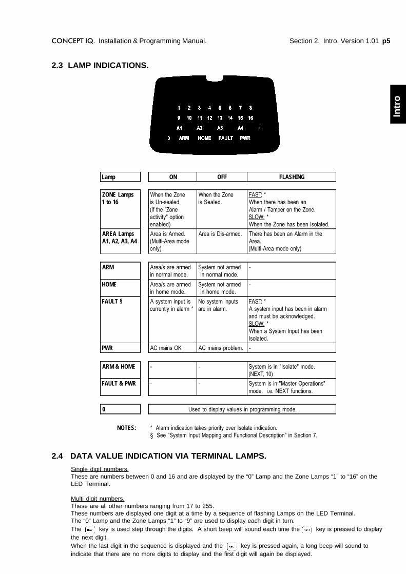
2.3 LAMP INDICATIONS.
2.4 DATA VALUE INDICATION VIA TERMINAL LAMPS.
Single digit numbers.These are numbers between 0 and 16 and are displayed by the “0” Lamp and the Zone Lamps “1” to “16” on theLED Terminal.
Multi digit numbers.These are all other numbers ranging from 17 to 255.These numbers are displayed one digit at a time by a sequence of flashing Lamps on the LED Terminal.The “0” Lamp and the Zone Lamps “1” to “9” are used to display each digit in turn.The key is used step through the digits. A short beep will sound each time the key is pressed to displaythe next digit.When the last digit in the sequence is displayed and the key is pressed again, a long beep will sound toindicate that there are no more digits to display and the first digit will again be displayed.
Lamp ON OFF FLASHING
ZONE Lamps1 to 16
When the Zoneis Un-sealed.(If the "Zoneactivity" optionenabled)
When the Zoneis Sealed.
FAST: *When there has been anAlarm / Tamper on the Zone.SLOW: *When the Zone has been Isolated.
AREA LampsA1, A2, A3, A4
Area is Armed.(Multi-Area modeonly)
Area is Dis-armed. There has been an Alarm in theArea.(Multi-Area mode only)
ARM Area/s are armedin normal mode.
System not armed in normal mode.
-
HOME Area/s are armedin home mode.
System not armed in home mode.
-
FAULT § A system input iscurrently in alarm *
No system inputsare in alarm.
FAST: *A system input has been in alarmand must be acknowledged.SLOW: *When a System Input has beenIsolated.
PWR AC mains OK AC mains problem. -
ARM & HOME - - System is in "Isolate" mode.(NEXT, 10)
FAULT & PWR - - System is in "Master Operations"mode. i.e. NEXT functions.
0 Used to display values in programming mode.
NOTES: * Alarm indication takes priority over Isolate indication.§ See "System Input Mapping and Functional Description" in Section 7.
p6 Section 2. Intro. Version 1.01 CONCEPT IQ. Installation & Programming Manual.
3. Installer Modes
The Default Installer Code is 2345.This Code should be changed as soon as possible after installation.When choosing a new Installer Code, ensure that a PIN code is chosen that will not be forgotten, while still providingsecurity against unauthorised access.
Installer Operations require the Installer to Access a number of different Modes.This is done by entering a valid Installer PIN code, then pressing the <NEXT> key before selecting the 2-digit Modenumber. e.g.Enter PIN; ... , then , then the Mode number; ,
This key sequence must be used to access all the Operational Modes described in this section.Remember that the <NEXT> “n”, “n” sequence must be preceded by the Installer PIN code.
e.g. To Enter Programming Mode:Enter PIN; ... , then , then the Mode number; ,
NOTE: Upon entering Programming mode the first digit of the Primary Telephone Number at Address 16 will bedisplayed.
The following pages provide full descriptions of each of the Installer Modes.
3.2 ACCESSING THE INSTALLER MODES.
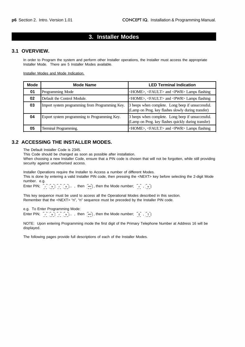
In order to Program the system and perform other Installer operations, the Installer must access the appropriateInstaller Mode. There are 5 Installer Modes available.
Installer Modes and Mode Indication.
3.1 OVERVIEW.
Mode Mode Name LED Terminal Indication
01 Programming Mode <HOME>, <FAULT> and <PWR> Lamps flashing
02 Default the Control Module. <HOME>, <FAULT> and <PWR> Lamps flashing
03 Import system programming from Programming Key. 3 beeps when complete. Long beep if unsuccessful.(Lamp on Prog. key flashes slowly during transfer)
04 Export system programming to Programming Key. 3 beeps when complete. Long beep if unsuccessful.(Lamp on Prog. key flashes quickly during transfer)
05 Terminal Programming. <HOME>, <FAULT> and <PWR> Lamps flashing
Section 2. Intro. Version 1.01 p7CONCEPT IQ. Installation & Programming Manual.
Intr
o
3.4 MODE “02”. DEFAULTING THE CONTROL MODULE.
Defaulting the Control Module allows the Installer to clear any current system programming from the Control Moduleand select a factory default database to simplify the programming task.
The Default Database options can be divided into 3 main options:Option 0: The Control Module memory is completely cleared with the exception of the Installer and Master
User Codes.Options 1 to 16: The Control Module memory is defaulted to the Factory settings shown in the table on the following
page AND the number of Zones specified by the Option selected, are programmed into Area 1.Option 49: The Master Code is defaulted to the Factory setting and all other programming is left intact.
CAUTION: Defaulting the Control Module will erase all current programming stored in the memory beforeimplementing any Factory default settings. (With the exception of Default Option 49)
Select the Defaulting Mode:Enter PIN; ... , then , then the Mode number; ,
The <HOME>, <FAULT> and <PWR> Lamps on the LED Terminal will flash simultaneously.
Select the Default OptionPress , then the Default Option (1 or 2 digits), then
DEFAULT OPTIONS:
0: Database is completely cleared except for Installer & Master Codes.1: Database is defaulted to Factory Default settings AND 1 Zone is programmed into the system.2: Database is defaulted to Factory Default settings AND 2 Zones are programmed into the system.3 to 15: Database is defaulted to Factory Default settings AND the specified number of Zones are programmed
into the system. i.e. 3 Zones to 15 Zones.16: Database is defaulted to Factory Default settings AND 16 Zones are programmed into the system.49: Master Code Default. Only the Master code is reset to the factory default. All other programming remains
unchanged.
NOTES:1) The product is dispatched from the factory Defaulted with Option 8 (Factory Default settings and 8 Zones)2) In Default Options 1 to 16, the Zones programmed into the system are assigned to Area 1.3) If Default options 9 to 16 are used, and Zones 9 to 16 are added using Zone Doubling (i.e. Not via an
Expander card), the “End-of-Line Resistor value” (Address 786) must be set to Type 14 - Zone Doubling.
Exit from Defaulting ModePress to exit.
Reset the Control Module:Disconnect the AC Input and the Battery from the Control Module, then re-connect.
This mode allows the Installer to program all of the system data and options.
To Select Programming Mode:Enter PIN; ... , then , then the Mode number; , .
See “Basic Programming Techniques” and “Types of Data” for more details of Programming Mode.
3.3 MODE “01”. PROGRAMMING MODE.
HARDWARE DEFAULT PROCEDURE.The system can also be set to the Factory Default settings (Same as Default Option 8) via a hardware procedure.
- Disconnect the battery and remove power from the Control Module.- Place a short circuit across Pins 2 & 3 of JP8 on the Control Module.- Re-apply power to the Control Module and reconnect the battery.- Remove the short circuit on JP8.
p8 Section 2. Intro. Version 1.01 CONCEPT IQ. Installation & Programming Manual.
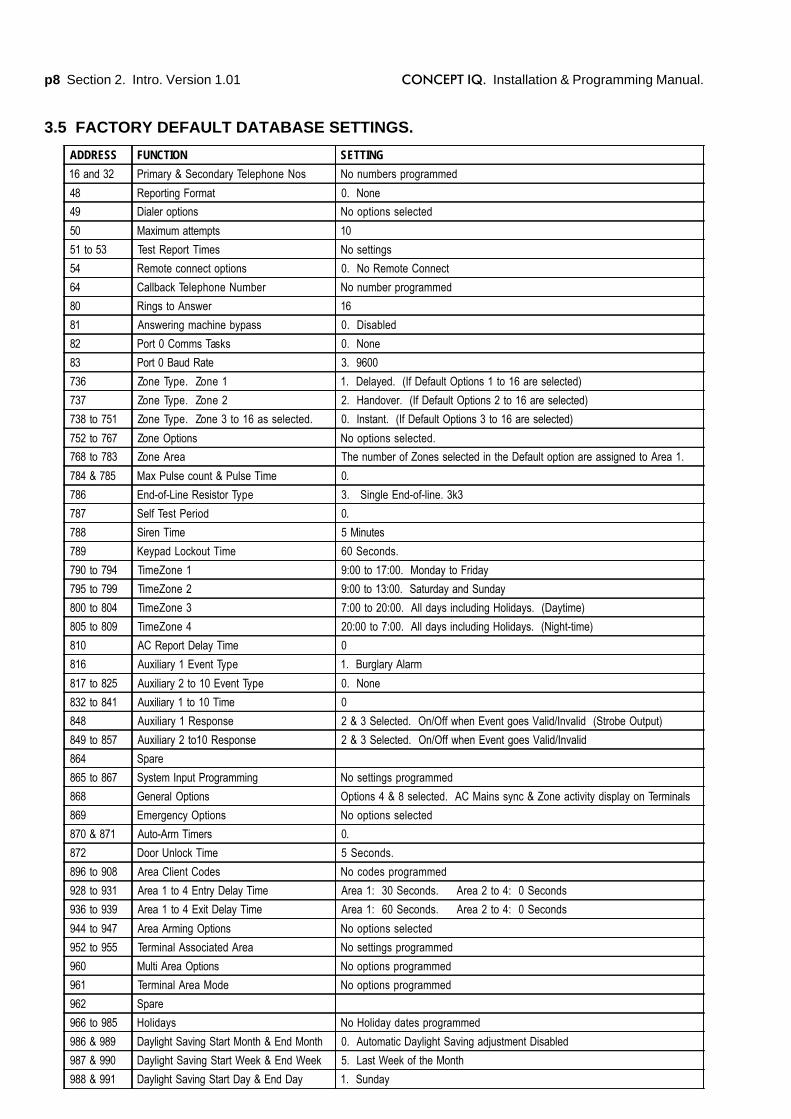
3.5 FACTORY DEFAULT DATABASE SETTINGS.
ADDRESS FUNCTION SETTING
16 and 32 Primary & Secondary Telephone Nos No numbers programmed
48 Reporting Format 0. None
49 Dialer options No options selected
50 Maximum attempts 10
51 to 53 Test Report Times No settings
54 Remote connect options 0. No Remote Connect
64 Callback Telephone Number No number programmed
80 Rings to Answer 16
81 Answering machine bypass 0. Disabled
82 Port 0 Comms Tasks 0. None
83 Port 0 Baud Rate 3. 9600
736 Zone Type. Zone 1 1. Delayed. (If Default Options 1 to 16 are selected)
737 Zone Type. Zone 2 2. Handover. (If Default Options 2 to 16 are selected)
738 to 751 Zone Type. Zone 3 to 16 as selected. 0. Instant. (If Default Options 3 to 16 are selected)
752 to 767 Zone Options No options selected.
768 to 783 Zone Area The number of Zones selected in the Default option are assigned to Area 1.
784 & 785 Max Pulse count & Pulse Time 0.
786 End-of-Line Resistor Type 3. Single End-of-line. 3k3
787 Self Test Period 0.
788 Siren Time 5 Minutes
789 Keypad Lockout Time 60 Seconds.
790 to 794 TimeZone 1 9:00 to 17:00. Monday to Friday
795 to 799 TimeZone 2 9:00 to 13:00. Saturday and Sunday
800 to 804 TimeZone 3 7:00 to 20:00. All days including Holidays. (Daytime)
805 to 809 TimeZone 4 20:00 to 7:00. All days including Holidays. (Night-time)
810 AC Report Delay Time 0
816 Auxiliary 1 Event Type 1. Burglary Alarm
817 to 825 Auxiliary 2 to 10 Event Type 0. None
832 to 841 Auxiliary 1 to 10 Time 0
848 Auxiliary 1 Response 2 & 3 Selected. On/Off when Event goes Valid/Invalid (Strobe Output)
849 to 857 Auxiliary 2 to10 Response 2 & 3 Selected. On/Off when Event goes Valid/Invalid
864 Spare
865 to 867 System Input Programming No settings programmed
868 General Options Options 4 & 8 selected. AC Mains sync & Zone activity display on Terminals
869 Emergency Options No options selected
870 & 871 Auto-Arm Timers 0.
872 Door Unlock Time 5 Seconds.
896 to 908 Area Client Codes No codes programmed
928 to 931 Area 1 to 4 Entry Delay Time Area 1: 30 Seconds. Area 2 to 4: 0 Seconds
936 to 939 Area 1 to 4 Exit Delay Time Area 1: 60 Seconds. Area 2 to 4: 0 Seconds
944 to 947 Area Arming Options No options selected
952 to 955 Terminal Associated Area No settings programmed
960 Multi Area Options No options programmed
961 Terminal Area Mode No options programmed
962 Spare
966 to 985 Holidays No Holiday dates programmed
986 & 989 Daylight Saving Start Month & End Month 0. Automatic Daylight Saving adjustment Disabled
987 & 990 Daylight Saving Start Week & End Week 5. Last Week of the Month
988 & 991 Daylight Saving Start Day & End Day 1. Sunday

Section 2. Intro. Version 1.01 p9CONCEPT IQ. Installation & Programming Manual.
Intr
o
Terminal Programming allows the Installer to define which Area is to be associated with the LED Terminal.NOTE: This Mode is only available if the Terminal is programmed for Multi-Area mode. (Address 960. Option 1must be Selected)
Select the Terminal Programming Mode:Enter PIN; ... , then , then the Mode number; ,
Select the Terminal Area Mode: (Not relevant to Enhanced Terminals which cannot be set to Multi-Area)Press to Set the current Terminal to Single Area Mode.
Press to Set the current Terminal to Multi Area Mode.
Note that this operation will Edit the relevant option in Address 961, Terminal Area Mode.When Single Area Mode is selected, the default “Associated Area” is Area 1 (General Area)
Select the Associated Area: (Single Area Mode must be selected in the previous step)To select the Associated Area for the current Terminal, press the number (1 to 4) of the Area.The Area selected will be displayed on the Area Lamps.A long beep will sound if the terminal is not in Single Area Mode or the wrong key is pressed.
Note that this operation will Edit the data in the relevant Addresses 952 to 955, Terminal 1 to 4 Associated Area.
Press to exit Terminal Programming Mode.
3.6 MODE “03”. IMPORT DATA FROM THE PROGRAMMING KEY.
3.7 MODE “04”. EXPORT DATA TO THE PROGRAMMING KEY.
The Programming Key.
The Concept IQ Programming Key is a portable non-volatile memory device housed in a convenient “key tag”.
The Programming Key allows system programming to be uploaded from the Control Module or downloaded to theControl Module by simply inserting the Programming Key into Serial Port 0 and performing a simple key sequenceon the LED Terminal.
A built-in Lamp on the Programming Key visually indicates when data transmission is active.
Importing Data from the Programming Key.
This Mode allows the Installer to copy the programming contents of the Programming Key into the Control Module.IMPORTANT NOTE: The new data will override the existing contents of the Control Module memory.
Connect the Programming Key to Serial Port 0 on the Control Module.
Select the Import Data Mode:Enter PIN; ... , then , then the Mode number; , .
The Lamp on the Programming Key will flash slowly to indicate data is being copied.The Terminal beeper will sound 3 short beeps if the operation was successful, or 1 long beep if unsuccessful.
This Mode allows the Installer to copy the programming contents of the Control Module into the Programming Key.IMPORTANT NOTE: The Control Module data will override the existing contents of the Programming Key.
Connect the Programming Key to Serial Port 0 on the Control Module.
Select the Export Data Mode:Enter PIN; ... , then , then the Mode number; , .
The Lamp on the Programming Key will flash quickly to indicate data is being copied.The Terminal beeper will sound 3 short beeps if the operation was successful, or 1 long beep if unsuccessful.
3.8 MODE “05”. TERMINAL AREA PROGRAMMING.

p10 Section 2. Intro. Version 1.01 CONCEPT IQ. Installation & Programming Manual.
To Select the Data to be Viewed or Edited.
When in programming mode, the Memory Address to be viewed or edited can be selected by the following keysequence:
Press , then the Address ... (2 or 3 digits - 16 to 988), then
Pressing will take you to the next Address.(This does not apply to Data programmed in sequential Addresses such as PIN codes, Telephone Numbers andClient codes)
The programming details of each Data Address in the following sections of this manual will only show the actualAddress number (nn...). Remember that the Installer must first access Programming Mode; and the Data AddressNumber must be preceded by the <OFF / #> key.
To Edit the Data.
The Data Value at this Address will then be displayed on the Terminal, and can be changed by the following keysequence:
Press , then the new Data Value or Option setting ... (1 to 16 digits*), then * Depending on the type of Data required.
To set the Data in the current Address to the Factory Default setting:Press , then , then
If you make a mistake while entering a value, press and enter that value again followed by the key.
Exiting the Installer Operations.
Press to exit any of the Installer Operations.
4.2 SELECTING AND PROGRAMMING THE DATA.
4. Programming Techniques
4.1 THE SYSTEM DATABASE.
The system programming is stored in Memory Addresses numbered 16 - 988.Programming the system involves three steps:
1) Enter Programming Mode.
Then for each item of Data to be programmed;2) Select the Memory Address to be programmed.3) Program the new Data Value or Options for that Address.

Section 2. Intro. Version 1.01 p11CONCEPT IQ. Installation & Programming Manual.
Intr
o
4.3 EXAMPLE OF PROGRAMMING.This example shows how Zone 1 would be changed to the “Hand-over” Input Type.
Zone 1 Input Type is stored in Address 736.
STEP 1. Enter programming mode.
Enter Installer PIN code; ... , then , then the Programming Mode number; ,
STEP 2. Enter the Address to be changed.
Press , then the Address , then
STEP 3. Enter the new Data Value.
Press , then the new Data Value , then
(0 = Instant, 1 = Delayed, 2 = Handover, 3 = 24Hr Burglary, etc.)
STEP 4. Repeat Steps 2 and 3 to perform any additional programming required.
Press , to advance to the next Address. (i.e. Address 737 in this example)ORPress , then the new Address ... , then
Enter the new Data Value as before.
STEP 5. Exit the programming mode.
Press
p12 Section 2. Intro. Version 1.01 CONCEPT IQ. Installation & Programming Manual.
5. Types of Data
5.2 “VALUE” DATA.
The range of Data values that can be stored in a Value Data Address is from 0 to 255.Depending on the parameter being set, the range is often a lot smaller. The data can be either a single digit or amultiple-digit number.e.g. Remote Connect Options: 0 to 2, Zone Type: 0 to 9, Dial Attempts: 1 to 16,
TimeZone Start / End Hour 0 to 23, AC Fail report delay (M) 0 to 60, Area Entry Delay (S): 0 to 255,etc.
Single digit numbers.These are numbers between 0 and 16 and are displayed by the “0” Lamp and the Zone Lamps “1” to “16” on theLED Terminal.
Multi digit numbers.These are all other numbers ranging from 17 to 255.These numbers are displayed one digit at a time by a sequence of flashing Lamps on the LED Terminal.The “0” Lamp and the Zone Lamps “1” to “9” are used to display each digit in turn.The key is used step through the digits. A short beep will sound each time the key is pressed to displaythe next digit.When the last digit in the sequence is displayed and the key is pressed again, a long beep will sound toindicate that there are no more digits to display and the first digit will again be displayed.
E.g. If the value at the Address is 120.When the Address is entered, The “1” Lamp will flash. (The flashing Lamp indicates that this value is a multi-digitnumber)When the <NEXT> key is pressed a short beep will sound and the “2” Lamp will now flash.When the <NEXT> key is pressed again, a short beep will sound and the “0” Lamp will flash.When the <NEXT> key is pressed again, a long beep will sound indicating there are no more new digits. The firstdigit (“1” Lamp) will flash.
Sequential numbers.Sequential numbers are a string of numbers where each digit is programmed into a series of sequential Addresses.This type of Value Data makes it easier for the Installer to program data such as PIN codes, Telephone Numbersand Client codes.To select the data, only the Start Address is entered. The Start Address and each subsequent Address onlycontains a single digit.Once the Start Address for the data is selected, the Installer can then enter in the entire string of numbers withouthaving to perform any operation to select the subsequent Addresses.
See next page for example.
When in Programming Mode there are two types of data that are stored in the Programming Addresses.The type of Data stored in each Address will depend on the type of parameter being defined.
1) “Value” data. A Numerical Data Value that:- Selects an Option when there are more than 2 alternatives to select from. e.g. Reporting Format or User Type.- Defines a Value or Quantity for a specific parameter. e.g. Entry and Exit Delay times or Number of Dial attempts.- Defines a Sequence of numbers for a specific parameter. e.g. PIN codes, Client codes and Telephone numbers.
2) “Option” data. Data field that allows the Installer to select between two alternatives (Select/De-select, Enable/Disable, Assign/Un-assign, etc.) for up to 8 Options or Items that relate to a particular feature.
(Similar to the Y / n options screens in Concept 3000 / Access 4000.)e.g. Setting Dialer options, Assigning Areas to a User, Defining options for Individual Zone Inputs, etc.
5.1 OVERVIEW.

Section 2. Intro. Version 1.01 p13CONCEPT IQ. Installation & Programming Manual.
Intr
o
5.3 “OPTION” DATA.
Option data is used to allow the Installer to select between two alternatives (Select/De-select, Enable/Disable,Assign/Un-assign, etc.) for up to 8 Options or Items that relate to a particular feature.
Option Data is displayed on the Zone 1 to 8 Lamps on the LED Terminal.When a Zone Lamp is ON, the option is Selected. (Enabled or Assigned)When a Zone Lamp is OFF, the option is De-selected. (Disabled or Un-assigned)
Editing option data.
Option Data is programmed by first selecting the Address of the Data to be edited in the normal manner.
Any number of specific options are then Selected or De-selected by the following method:1) Check the current setting of the option on the Zone Lamps.2) For each option that needs to be changed, Press , then the option number (1 to 8), then .
This procedure toggles the setting of the selected option.i.e. If the option was De-selected, it will be Selected. If the option was already Selected, it will be De-selected.
To Select ALL available options: Press , then , then .
To De-select ALL available options: Press , then , then .
To set ALL available options to the factory default settings: Press , then , then .
Example.
“Dialer Options” are Option Data and are programmed in Address 49. This data sets which types of events will bereported via dialer: 1 Enable Alarms reported via dialer.
2 Enable Restores reported via dialer.3 Enable Open / Close reported via dialer.4 Enable Programming Change reported via dialer.5 Enable Sending Open Report only if an alarm has occurred.
To Enable “Alarms”, “Restores” and “Open Report only after alarm”, the following procedure would be performed:
1) Enter Installer PIN code; ... , then , then the Programming Mode number; ,
2) Select the Address for Dialer Options. Press , then , then
3) Enable the three options required. (Assuming none of the options are currently enabled)Press , then , then
Press , then , then
Press , then , then
(Remember that the same key sequence is used to Disable an option that is already Enabled.
4) Check Zone Lamps 1 to 8 to ensure that the required options have been selected successfully.Zone Lamps 1, 2 and 5 should be ON. All other Zone Lamps should be OFF.
5) Select the next Address or Start Address to program, or Exit Programming Mode.
E.g. To program the data “1 Pause 9 8 7 6 5 4 3 2” as the Primary Telephone Number.
1) Enter Installer PIN code; ... , then , then the Programming Mode number; ,
2) Press , then the Start Address for the Primary Telephone Number , then
3) Press , then the new Data string , then
4) Select the next Address or Start Address to program, or Exit Programming Mode
(Note: The <Next> key is used to program a “PAUSE”).
Sequential Number data is displayed one digit at a time by a sequence of flashing Lamps in the same manner asMulti-digit numbers described above.
p14 Section 2. Intro. Version 1.01 CONCEPT IQ. Installation & Programming Manual.
6. Recommended Programming Sequence
1. Determine the number of Burglary Alarm Zone Inputs that will be connected to the system.For ease of programming; If Entry/Exit Zones are to be used, it is recommended that:-The Zone Input device that will start the Entry Timer is connected to Zone 1.-The “Handover” Zone Input device (If required) is connected to Zone 2.-Other Burglary Alarm Zone Input devices are connected to the lowest Zone Input numbers.-Other types of Zone Input devices are connected to the higher Zone Input numbers.
2. Logon to the Terminal using the Installer PIN code and select Mode 2 - Defaulting the Control Module.-Enter PIN, <NEXT>, 0, 2.
3. Select the Default Option that matches the number of Burglary Alarm Zone Inputs required.-<*>, nn, <ENTER>. Where “nn” is the Default option. 0 = No Zones, 1 = 1 Zone, 8 = 8 Zones, etc.The Database will be defaulted as per the settings shown in the table on page 8.
4. IF Multi-Area operation, or Sub-Area Functionality is required, program the Multi-Area options.Address 9601 Multi-Area Mode 4 Include Area 2 in Area 4 Sub-Area list2 Enable Area 4 as Sub-Area 5 Include Area 3 in Area 4 Sub-Area list3 Include Area 1 in Area 4 Sub-Area list.
5. Program the Global Zone Options. (IF there are variations required from the Default programming)IF Pulse counting is to be used:
Program the “Pulse Count” & “Pulse Time”. Addresses 784 & 785.
IF the End-of-Line Resistors are a value other than “3k3 Single End-of-Line”:Program the “End-of-Line Resistor” Value. Address 786.
IF Zone Self-Testing is required:Program the Zone Self-Test period. Address 787.
6. Program the Individual Zone Inputs. (IF there are variations required from the Default programming)-Program the Zone Type: Addresses 736 (Zone 1) to 751 (Zone 16)0 Instant. 5 24 Hour Panic.1 Delayed. 6 24 Hour Duress.2 Handover. 7 Door Bell.3 24 Hour Burglary. 8 Key-switch.4 24 Hour Fire 9 Key-switch Home mode.
-Program the Zone Options: Addresses 752 (Zone 1) to 767 (Zone 16)1 Silent. 5 Self-Test Zone.2 One-shot Siren. 6 Day Alarm Zone.3 One-shot Dialer.* 7 Home Zone.4 Pulse Count. 8 Normally Open.* Highly recommended if Domestic Dialer communications format is to be used.
-Program the Zone Areas: Addresses 768 (Zone 1) to 783 (Zone 16)1 Zone assigned to Area 1. 5 Zone assigned to Area 3.2 Zone assigned to Area 2. 6 Zone assigned to Area 4.
7. Enable any additional General System Options that are required.Address 8681 Auto-Isolate on Arming. 5 Automatic Battery Testing.2 Quick Arming. 6 “Latching” Key-switch operation.3 6 digit PIN codes. 7 Allow Master Users to edit Telephone numbers.4 * Clock synchronized to 50Hz AC Mains. 8 * Display Zone activity when disarmed.*Already enabled by default.
8. Enable any of the Emergency Options that are required.Address 8691 Panic Alarms activate Siren. 5 Medical Alarms activate Siren.2 Panic Alarms activate Dialer. 6 Medical Alarms activate Dialer.3 Fire Alarms activate Siren. 7 Duress Alarms activate Dialer.4 Fire Alarms activate Dialer.

Section 2. Intro. Version 1.01 p15CONCEPT IQ. Installation & Programming Manual.
Intr
o
9. IF Area 1 Entry/Exit Delay default values need to be changed, ORIF Entry/Exit Delays are required in Areas 2, 3 or 4, program/edit the Area Entry and/or Exit Delay times.Addresses 928 to 931 Area 1 to 4 Entry Delay. Default = Area 1: 30 Seconds.Addresses 936 to 939 Area 1 to 4 Exit Delay. Default = Area 1: 60 Seconds.
10. Enable the System Inputs that are required to activate the Siren.Address 865.1 AC Fail. 5 Comms Fail / System Reset.2 Low Battery. 6 Siren Monitor.3 Cabinet Tamper. 7 PWR Fuse / Battery Fuse.4 Keypad Lockout.
NOTE: If any of these options are selected, check the “System Input Siren Type” setting. Address 867.0 = 1 second burst (Default). 1 = 10 second burst. 2 = 1 Sec burst every 60 Secs for 5 Mins.
11. Enable the System Inputs that are required to activate the Dialer.Address 866.1 AC Fail. 5 Comms Fail / System Reset.2 Low Battery. 6 Siren Monitor.3 Cabinet Tamper. 7 PWR Fuse / Battery Fuse.4 Keypad Lockout. 8 Zone Self-Test Fail.
12. Program any Timers that may be required.Address 788: Siren Time. (Defaulted to 5 Minutes)Address 789: Keypad lockout time (Defaulted to 60 Seconds)Address 810: AC Report delay. CAUTION. Read details in Section 4 - Times before programming.
13. IF any Areas or Auxiliaries are to be controlled automatically by a TimeZone, edit the required TimeZone/s.Addresses 790 to 809. (All TimeZones have Default settings. Check the details before editing)See Section 4 -Times for details.
NOTE: If the TimeZones are required to take account of Holidays, program the required Holiday Dates.Addresses 966 to 985 See Section 4 -Times for details.
14. Program any additional Auxiliary outputs required.(NOTE: Auxiliary 1 is already programmed with default settings for controlling a Strobe.It is set to the “Burglary Alarm” Event Type and has “Auxiliary Response” options 2 & 3 selected)-Program the Auxiliary Event Type: Addresses 816 (Aux 1) to 825 (Aux 10) (See Sect 8 [Auxes] for details)
-Program an Auxiliary Timer if required: Addresses 832 (Aux 1) to 841 (Aux 10)
-Program the Auxiliary Response: Addresses 848 (Aux 1) to 857 (Aux 10)1 Output is inverted. (Normally Closed) 3 Aux Off when Event goes Invalid.2 Aux On when Event goes Valid. 4 Aux timer will time in Minutes.
15. IF the system is programmed for Multi-Area operation (see Step 4), program the Terminals.-Program the Terminal Area Mode if any Terminals are required to operate in Single-Area Mode. Address 961.1 Sets Terminal 1 to Single-Area mode. 3 Sets Terminal 3 to Single-Area mode.2 Sets Terminal 2 to Single-Area mode. 4 Sets Terminal 4 to Single-Area mode.
IF any Terminals are set to Single Area mode, assign the associated Area.Addresses 952 (Terminal 1) to 955 (Terminal 4)1 Assign Area 1. (Default) 3 Assign Area 3.2 Assign Area 2. 4 Assign Area 4.
16. IF automatic Daylight Saving adjustment is required, program the start and end dates.Addresses 986 to 991. See Section 4 -Times for details.
17. IF a TimeZone is required to Arm an Area, program the Area Arming Options.Addresses 944 to 947 Area 1 to 40 No TimeZone control 3 TimeZone 3 will control the Area.1 TimeZone 1 will control the Area. 4 TimeZone 4 will control the Area.2 TimeZone 2 will control the Area.
NOTE: If a Pre-arm warning is required, program the “Autoarm Pre-warn time”. Address 870.

p16 Section 2. Intro. Version 1.01 CONCEPT IQ. Installation & Programming Manual.
18. IF the Re-Autoarm function is required, program a Re-Autoarm time.Address 871.
NOTE: If a Pre-arm warning is required, program the “Autoarm Pre-warn time”. Address 870.
19. IF the system has Access Control via one or more Enhanced Terminals, program the Door Times.-Program the Door Unlock time. Address 872 (Default is 5 Seconds)
20. IF the system is to report in Contact ID or Domestic Dialer formats, program the Dialer options.-Program the Primary & Secondary Telephone numbers. Addresses 16 and 32.
-Select the Reporting Format. 1 = Contact ID. 2 = Domestic. Address 48.
-Select the required Dialer Options. Address 49.1 Alarms reported via Dialer. 5 Openings reported only after an alarm.2 Restores reported via Dialer. 6 Remote control via DTMF Card enabled.*3 Area Open/Close reported via Dialer. 7 Isolates reported via Dialer.4 Programming change reported via Dialer.
* DTMF Card must be fitted to Control Module.
-Edit the maximum dial attempts if required. (Default = 10 attempts) Address 50.
-Program the Client Code/s. Area 1 only if system is programmed for Single Area operation.Address 896: Area 1 Address 904: Area 3Address 900: Area 2 Address 908: Area 4
21. IF periodic Test Reports are to be sent to the Central Monitoring Station, program the Test Report options.-Program the Test Report period. Address 51.0 No Test Report. 2 Every Monday.1 Every Day. 3 First day of every Month.
-Program the time of day the Test Report is to be sent. Address 52: Hour. Address 53: Minute.
22. IF Remote connection for Upload/Download or Telephone is required, program the Remote Connect options.-Program the Remote Connect Options. Address 540 = No Remote connect. 1 = Remote Connect allowed. 2 = Remote connect with Callback.
-Program the number of rings before answer. Address 80.
-IF Answering machine (Fax machine) bypass is required, program the “Follow-on” time.Address 81. (See Section 10 [Communications] for details)
-IF the “Remote connect with Callback” option was selected, program a “Callback Telephone no”. Address 64.
23. IF the Serial Port on the Control Module is to be used, program the Serial Port options.-Select the Communications Task. Address 82. 3 = Upload / Download.
-Select the Baud Rate. (Default is 9600) Address 83 0 = 300. 1 =1200. 2 = 4800. 3 = 9600
24. Change the Installer PIN code.Address 96. This should be done before the system is commissioned and handed over to the client.Ensure that a new PIN code is chosen that will not be forgotten, while still providing security against unauthorisedaccess.
25. Program the Users.A Master User Code must be used to program the Users. See the User’s Manual for details.
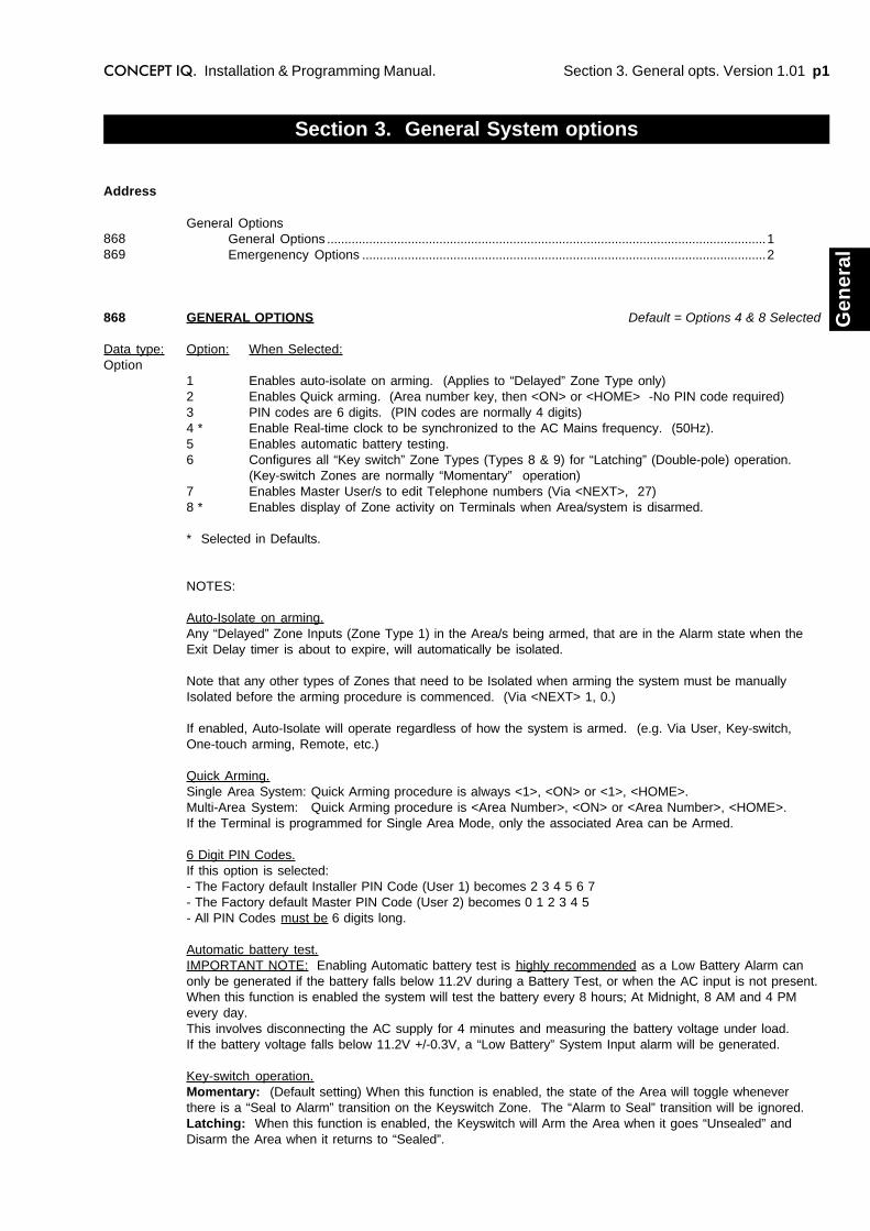
Section 3. General opts. Version 1.01 p1CONCEPT IQ. Installation & Programming Manual.
Gen
eral
Section 3. General System options
General OptionsGeneral Options .............................................................................................................................1Emergenency Options ...................................................................................................................2
Address
868869
868
Data type:Option
GENERAL OPTIONS Default = Options 4 & 8 Selected
Option: When Selected:
1 Enables auto-isolate on arming. (Applies to “Delayed” Zone Type only)2 Enables Quick arming. (Area number key, then <ON> or <HOME> -No PIN code required)3 PIN codes are 6 digits. (PIN codes are normally 4 digits)4 * Enable Real-time clock to be synchronized to the AC Mains frequency. (50Hz).5 Enables automatic battery testing.6 Configures all “Key switch” Zone Types (Types 8 & 9) for “Latching” (Double-pole) operation.
(Key-switch Zones are normally “Momentary” operation)7 Enables Master User/s to edit Telephone numbers (Via <NEXT>, 27)8 * Enables display of Zone activity on Terminals when Area/system is disarmed.
* Selected in Defaults.
NOTES:
Auto-Isolate on arming.Any “Delayed” Zone Inputs (Zone Type 1) in the Area/s being armed, that are in the Alarm state when theExit Delay timer is about to expire, will automatically be isolated.
Note that any other types of Zones that need to be Isolated when arming the system must be manuallyIsolated before the arming procedure is commenced. (Via <NEXT> 1, 0.)
If enabled, Auto-Isolate will operate regardless of how the system is armed. (e.g. Via User, Key-switch,One-touch arming, Remote, etc.)
Quick Arming.Single Area System: Quick Arming procedure is always <1>, <ON> or <1>, <HOME>.Multi-Area System: Quick Arming procedure is <Area Number>, <ON> or <Area Number>, <HOME>.If the Terminal is programmed for Single Area Mode, only the associated Area can be Armed.
6 Digit PIN Codes.If this option is selected:- The Factory default Installer PIN Code (User 1) becomes 2 3 4 5 6 7- The Factory default Master PIN Code (User 2) becomes 0 1 2 3 4 5- All PIN Codes must be 6 digits long.
Automatic battery test.IMPORTANT NOTE: Enabling Automatic battery test is highly recommended as a Low Battery Alarm canonly be generated if the battery falls below 11.2V during a Battery Test, or when the AC input is not present.When this function is enabled the system will test the battery every 8 hours; At Midnight, 8 AM and 4 PMevery day.This involves disconnecting the AC supply for 4 minutes and measuring the battery voltage under load.If the battery voltage falls below 11.2V +/-0.3V, a “Low Battery” System Input alarm will be generated.
Key-switch operation.Momentary: (Default setting) When this function is enabled, the state of the Area will toggle wheneverthere is a “Seal to Alarm” transition on the Keyswitch Zone. The “Alarm to Seal” transition will be ignored.Latching: When this function is enabled, the Keyswitch will Arm the Area when it goes “Unsealed” andDisarm the Area when it returns to “Sealed”.

p2 Section 3. General opts. Version 1.01 CONCEPT IQ. Installation & Programming Manual.
EMERGENCY OPTIONS Default = No Options Selected
These options determine how the PANIC, FIRE, MEDICAL, and DURESS alarms will be processed.These settings will affect:- Panic alarms generated by Keypad Panic AND Zone Inputs programmed as the “24 Hour Panic” Zone
Type. (Zone Type 5)- Fire alarms generated by Keypad Fire. (Siren and Dialer options for “24Hr Fire Zones are determined by
Zone Options programming)- Medical alarms generated by Keypad Medical.- Duress alarms generated by Keypad Duress AND Zone Inputs programmed as the “24Hr Duress” Zone
Type. (Zone Type 6)
Option: When Selected:
1 Panic alarms will activate the Siren.2 Panic alarms will activate the Dialer.
3 Fire alarms will activate the Siren.4 Fire alarms will activate the Dialer
5 Medical alarms will activate the Siren.6 Medical alarms will activate the Dialer
7 Duress alarms will activate the Dialer.
When an Emergency Alarm activates the Siren, the Siren will run for the programmed Siren time, OR until theAlarm is acknowledged at a Terminal. (via NEXT 25; Fault Analysis)
Address
869
Data type:Option
Section 4. Times. Version 1.01 p1CONCEPT IQ. Installation & Programming Manual.
Tim
es
SIREN TIME Default = 5 Minutes
This Address sets the time the siren will sound when an alarm has occurred on a Zone Input.
Note that an alarm on a Zone Input will only activate the Siren when:- The Zone Type selected is in the range of Type 0 to Type 5. (Address 736 [Zone 1] to 751 [Zone 16])- The Zone Options must have Option 1 (Silent), Disabled.- For Zone Types 4 (24Hr Fire) & 5 (24Hr Panic), Siren activation must also be enabled in the “Emergency
Options”. (Address 869: Option 1-Panic alarm sounds Siren. Option 3-Fire alarm sounds Siren)- The Zone Input must have at least one Area assigned.
The Siren Time does not apply to System Inputs. Siren operation for System Inputs is determined by thesettings in Address 865 - System Input Siren enable, and Address 867 - System Input Siren Type.
KEYPAD LOCKOUT TIME Default = 60 Seconds
This sets the time the Terminal keypad will be locked out when five incorrect logins (PIN code attempts) in arow have occurred on a keypad.
For Keypad Lockout to function, the setting must be non-zero.See Section 7; “System Inputs” if Siren activation (Address 865, Option 4) or Dialer activation (Address 866,Option 4) are required for Keypad Lockout.
Section 4. Time Programming
Siren Time ..................................................................................................................................................1Keypad Lockout Time................................................................................................................................1TimeZones
TimeZone 1 Start Hour ..................................................................................................................2TimeZone 1 Start Minute ...............................................................................................................2TimeZone 1 End Hour ...................................................................................................................2TimeZone 1 End Minute ................................................................................................................2TimeZone 1 Days Of Week ...........................................................................................................2TimeZone 2 (5 Addresses) ............................................................................................................2TimeZone 3 (5 Addresses) ............................................................................................................2TimeZone 4 (5 Addresses) ............................................................................................................2
AC Report Delay ........................................................................................................................................3Holidays
Holiday Month (10 Addresses) ....................................................................................................3Holiday Day (10 Addresses) ........................................................................................................3
Daylight SavingDaylight Saving Start Month ........................................................................................................3Daylight Saving Start Week .........................................................................................................3Daylight Saving Day-of-week in Start Week ...............................................................................3Daylight Saving End Month ..........................................................................................................4Daylight Saving End Week ..........................................................................................................4Daylight Saving Day-of-week in End Week ................................................................................4
Real-Time Clock ........................................................................................................................................4
Other Timers:
“Area Entry Delay” & “Area Exit Delay” Times. See Section 5. Areas.“Autoarm Prewarn” & Re-Autoarm” Times. See Section 5. Areas.“Pulse Time” for Pulse Counting feature. See Section 6. Zones“Auxiliary Timers”. See Section 8. Auxiliaries.“Door Open Time”. See Section 9. Terminals.
Address
788789
790791792793794795 to 799800 to 804805 to 809810
966 to 984967 to 985
986987988989990991NEXT 23
788
Data type:Value
Range:0 - 255 Min.
789
Data type:Value
Range:0 - 255 Sec.

p2 Section 4. Times. Version 1.01 CONCEPT IQ. Installation & Programming Manual.
TIMEZONES
TimeZones can be programmed to define a Start time and End time, and the Days of the Week on which theTimeZone will be valid. TimeZone programming also provides a “Holiday” option to be enabled when assign-ing the Days, to allow the TimeZone to still be valid on any dates defined as Holidays.Once programmed, TimeZones can be used to arm & disarm Areas &/or control Auxiliary outputs automati-cally.
START AND END TIMESThe Start and End Times are defined in 4 separate Addresses for each TimeZone.
TIMEZONE 1 START HOUR Default = 9
This Address defines the Hour component of the Start Time.
TIMEZONE 1 START MINUTE Default = 0
This Address defines the Minute component of the Start Time.
TIMEZONE 1 END HOUR Default = 17
This Address defines the Hour component of the End Time.
TIMEZONE 1 END MINUTE Default = 0
This Address defines the Minute component of the End Time.
TIMEZONE 1 DAYS OF THE WEEK Default = 2, 3, 4, 5, 6 Selected. (Mon - Fri)
Option : When Selected:
1 Sunday ¯|2 Monday |3 Tuesday | The TimeZone will be valid on the specified Day, or Days,4 Wednesday | unless the date has been defined as a Holiday.5 Thursday |6 Friday |7 Saturday _|
8 Holiday The TimeZone will always be valid on the Days of the Week selected above,regardless of whether the date has been defined as a Holiday.
The default setting is 9:00 – 17:00 on all Weekdays (Working Hours)
TIMEZONE 2 (5 Addresses)
The default setting is 9:00 – 13:00 on Weekend Days (Overtime Hours)
TIMEZONE 3 (5 Addresses)
The default setting is 7:00 – 20:00 on every Day (Day-time)
TIMEZONE 4 (5 Addresses)
The default setting is 20:00 – 7:00 on every Day (Night-time)
Address
Data type:Value
790
Range:0 - 23
791
Range:0 - 59
792
Range:0 - 23
793
Range:0 - 59
794
Data type:Option
795to799
800to804
805to809
Section 4. Times. Version 1.01 p3CONCEPT IQ. Installation & Programming Manual.
Tim
es
AC REPORT DELAY Default = 0
This location sets the time period the AC will need to be continuously disconnected from the system beforean alarm will be reported to the central station. When the AC is removed from the system the keypad ACindicator will immediately indicate the AC has been removed.
CAUTION: If an AC Report Delay time is programmed, the system Owner/User must be made aware that ifthe AC supply fails and the Battery is in poor condition, the system may shut down before the AC fail isreported to the Central Station, leaving the premises unmonitored and/or unprotected.If an AC Report Delay is required, ensure that Automatic battery testing is enabled (Address 868, Option 5),keep the period as short as possible, and advise the system Owner/User of the implications of the function.
HOLIDAYS No Default programming
HOLIDAY 1 MONTH
This Address sets the Month component of the Date for Holiday 1.A value of 0 means no Date is defined for Holiday 1.
HOLIDAY 1 DAY
This Address sets the Day component of the Date for Holiday 1.A value of 0 means no Date is defined for Holiday 1.
HOLIDAY 2 TO HOLIDAY 10
Holiday Number: 1 2 3 4 5 6 7 8 9 10Month Address: 966 968 970 972 974 976 978 980 982 984Day Address: 967 969 971 973 975 977 979 981 983 985
DAYLIGHT SAVING
IMPORTANT NOTE: The Daylight Saving “Start Month” and “End Month” must both be non-zero before anyautomatic Daylight Saving adjustment will be performed.See the information following these programming options for help in determining the Daylight Saving Startand End dates to be programmed.
Note that Daylight Saving adjustment occurs at 00:00 (Midnight) on the specified day.
DAYLIGHT SAVING START MONTH Default = 0
This Address sets the Month component of the Date for the Start of Daylight Saving.A value of 0 means no automatic Daylight Saving adjustment.
DAYLIGHT SAVING START WEEK Default = 5. Last Week of the Month
This Address sets the Week-Of-Month component of the Date for the Start of Daylight Saving.
DAYLIGHT SAVING DAY-OF-WEEK IN START WEEK Default = 1. Sunday
This Address sets the Day-Of-Week component of the Date for the Start of Daylight Saving.1 Sunday 4 Wednesday 6 Friday2 Monday 5 Thursday 7 Saturday3 Tuesday
Address
810
Data type:Value
Range:0 - 60 Min.
Data type:Value
966
Range:0 - 12
967
Range:0 - 31
968to985
Data type:Value
986
Range:0 - 12
987
Range:1 - 5
988
Range:1 - 7

p4 Section 4. Times. Version 1.01 CONCEPT IQ. Installation & Programming Manual.
DAYLIGHT SAVING END MONTH Default = 0
This Address sets the Month component of the Date for the End of Daylight Saving.A value of 0 means no automatic Daylight Saving adjustment.
DAYLIGHT SAVING END WEEK Default = 5. Last Week of the Month
Programmed as per Start Week.
DAYLIGHT SAVING DAY-OF-WEEK IN END WEEK Default = 1. Sunday
Programmed as per Start Day-Of-Week.
DAYLIGHT SAVING TIME (DST) START AND END DATES.
AustraliaIn NSW, ACT, VIC and SA, DST normally starts on the last Sunday in October, and ends on the last Sundayin March.e.g. 28 October 2001 to 31 March 2002
27 October 2002 to 30 March 200326 October 2003 to 28 March 200431 October 2004 to 27 March 2005
In TAS, DST normally starts on the first Sunday in October, and ends on the last Sunday in March.e.g. 7 October 2001 to 31 March 2002
6 October 2002 to 30 March 20035 October 2003 to 28 March 20043 October 2004 to 27 March 2005
New ZealandDaylight Saving Time normally starts on the first Sunday in October, and ends sometime in March.
EuropeDaylight Saving Time normally starts on the last Sunday in March, and ends on the last Sunday in October.e.g. 25 March 2001 to 28 October 2001
NOTE: These dates are only a guide, and should be checked with a reliable local source.
Comprehensive information on DST Start and End dates for most world locations can be found at:Time and date.com http://www.timeanddate.com/time/
SET THE REAL-TIME CLOCK.
Press <*>, then enter the current Time and Date as an 11 digit data string, followed by the <ENTER> key.Note that the Real-Time Clock must be re-programmed to the current time and date whenever the ControlModule is powered down. i.e. The AC supply and the battery are disconnected.
The data is entered in the following order: mm:hh ; DD:MM:YY ; di.e. minute, minute (00 - 59); hour, hour (00 - 23); Day, Day (01 - 31);
Month, Month (01 - 12); Year, Year (00 - 99); day of week (1 Sunday - 7 Saturday)
e.g.TIME & DATE: DATA STRING:1) 07:24 AM, Monday, June 5, 2001 2,4,0,7,0,5,0,6,0,1,2, <ENTER>2) 05:15 PM, Thursday, September 20, 2001 1,5,1,7,2,0,0,9,0,1,5, <ENTER>
To view the current Time and Date, enter the Real-Time Clock Programming Mode and the first digit of theTime and Date Data will be displayed on the Terminal Zone Lamps.
Press the <NEXT> key to step through the 13 digits in the Time and Date Data. The first 2 digits are the“Seconds”. When the end of the data is reached, a long beep will sound to indicate there are no morecharacters to display, and the first digit will again be displayed.
989
990
991
NEXT 23
Section 5. Area Programming. Version 1.01 p1CONCEPT IQ. Installation & Programming Manual.
Are
as
Section 5. Area Programming
Area Modes ................................................................................................................................................1Multi Area Systems ....................................................................................................................................1Multi Area Options .....................................................................................................................................1Area Entry Delay........................................................................................................................................1Area Exit Delay ..........................................................................................................................................1Area Arming Options .................................................................................................................................2Area AutoArm Pre-warn time ....................................................................................................................2Area Re-AutoArm time ..............................................................................................................................2
AREA MODES
The system is designed to operate in Single Area or Multi-Area mode.
-In Single Area mode the system only uses one area, the “General Area” or “Area 1”.When Single Area mode is selected, the Area Lamps on the Terminal are not used and any Multi-Areaprogramming or operating functions are ignored.-When Multi-Area mode is selected, up to four separate Areas can be used. The Area Lamps on theTerminal indicate the status of each individual Area.
MULTI-AREA SYSTEMS
When the system operates in Multi-Area mode, it can be configured as four separate Areas, or as 3 Areaswith Area 4 as the Sub-Area.Sub-Area Mode. When this mode is selected, Area 4 will only be armed when all the Areas included inArea 4’s “Sub-Area list” are armed. When this mode is selected, Area 4 can be Disarmed from a Terminalor Keyswitch, but will not Arm unless all the Areas in the Sub-Area List are Armed.
NOTE: If an Entry/Exit Area is required in a Multi-Area system, Area 1 is recommended.
MULTI-AREA OPTIONS Default = No Options Selected
If the system is in Single Area mode, none of the Sub-Area options need to be programmed.
Option: When Selected:1 Enables Multi-area mode. (Default is Single area mode)2 Enables Area 4 as the Sub-Area.3 Includes Area 1 in the Area 4 Sub-Area list.4 Includes Area 2 in the Area 4 Sub-Area list.5 Includes Area 3 in the Area 4 Sub-Area list.
AREA ENTRY DELAY TIME Default = Area 1: 30 Seconds
These Addresses set the Entry time to be applied to Zone Inputs programmed as Delayed Zones.i.e. Zone Types 1 (Delayed) and 2 (Handover).
Area Number: 1 2 3 4Entry Delay Time Address: 928 929 930 931
AREA EXIT DELAY TIME Default = Area 1: 60 Seconds
These Addresses set the Exit time to be applied to Zone Inputs programmed as Delayed Zones.i.e. Zone Types 1 (Delayed) and 2 (Handover).
Area Number: 1 2 3 4Exit Delay Time Address: 936 937 938 939
Address
960928 to 931936 to 939944 to 947870871
960
Data type:Option
928to931
Data type:Value
Range:0 - 255 Sec.
936to939
Data type:Value
Range:0 - 255 Sec
p2 Section 5. Area Programming. Version 1.01 CONCEPT IQ. Installation & Programming Manual.
Address
944to947
Data type:Value
Range:0 - 4
870
Data type:Value
Range:0 - 255 Sec.
871
Data type:Value
Range:0 - 255 Min.
AREA ARMING OPTIONS Default = 0 (All Areas)
The Area Arming options allow a TimeZone to be assigned to the Area causing the Area to automatically Armwhen the TimeZone goes Invalid.
Note that when the TimeZone goes Invalid and the Area Arms, it does not force the Area to remain in theArmed state for the duration of the Invalid period.i.e. The control function only occurs on the Valid-to-Invalid transition or “edge”.This means the Area can still be controlled by other entities, if required, such as:-User control via PIN codes and Keyswitches, etc.-Automatic control via the Re-Autoarm function.-Remote Control.
Area Number: 1 2 3 4Area Arming Options: 944 945 946 947
Value: When Selected:0 No TimeZone control. 3 TimeZone 3 will control the Area.1 TimeZone 1 will control the Area. 4 TimeZone 4 will control the Area.2 TimeZone 2 will control the Area.
NOTES: 1) If a System Reset occurs and the TimeZone is currently Invalid, the Area will Auto-arm.2) Auto-arm will Force-arm the Area and will only auto-isolate Delayed Zone Types. Any otherZone Types that are un-sealed when the Area arms, will go into alarm.
AUTOARM PRE-WARN TIME Default = 0
This Address determines the time period that a warning indication will be provided when an Area is about tobe automatically armed by a TimeZone, or by the Re-Autoarm function.
A value of 0 means no Pre-warning. Note that the Pre-warn time is added to the Auto-arm time. e.g. If theArea is programmed to arm at 7 PM with a Pre-warn time of 120 Seconds, the Area will arm at 7:02 PM.
The Autoarm Pre-warn indication is provided by Terminals associated with the Area about to be armed, andby the relevant Auxiliary Event Types; 45 (Area 1) to 48 (Area 4).
RE-AUTOARM TIME Default = 0
The Re-Autoarm function allows one or more Areas to be programmed to automatically arm when no activityis detected on the Zone Inputs in the Area for a specified period of time.This function can be used for a number of purposes including:-The ability to ensure that Areas are not accidently left dis-armed when all personnel have vacated the site.-Turning off particular building services (lights, aircon, etc) when no personnel are detected in the Area.-Keyswitch or Button operated “Deadman” functions.
To implement the Re-Autoarm feature, the following options must be programmed:1) The Area must be programmed as an Autoarm Area. i.e. A TimeZone must be assigned to the Area
in the Area Arming options. ( Address 944 [Area 1] to 947 [Area 4] )NOTE: If you do not wish the Area to turn On at the End time specified in the TimeZone, assign aTimeZone that has the Start and End times programmed to 00:00.
2) Program a “Re-Autoarm Time” to a value of 1 to 255 to specify how long the Area can remain dis-armed without detecting any Zone Input activity. (If this period expires without any Zone Input activitybeing detected, the Area will automatically arm)
Settings:0 There will be no Re-autoarm function.
1 to 255 a) When an Autoarm Area is disarmed, the Re-Autoarm timer will be started for that Area.b) While the timer is running, any Zone Input activity detected in the Area will cause the timer to bere-started. (Thereby preventing the Area from Re-arming)c) When the Re-Autoarm timer has run for the specified time without detecting any Zone Inputactivity, the Area will automatically be Re-armed.
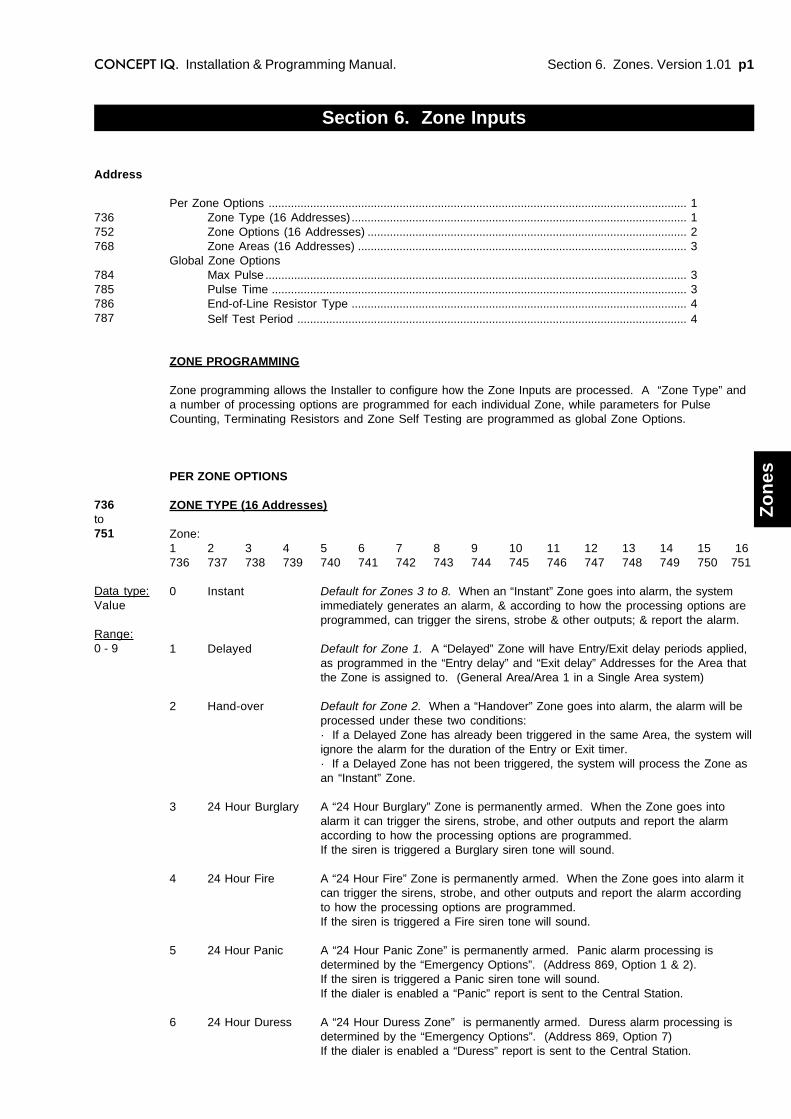
Section 6. Zones. Version 1.01 p1CONCEPT IQ. Installation & Programming Manual.
Zo
nes
ZONE PROGRAMMING
Zone programming allows the Installer to configure how the Zone Inputs are processed. A “Zone Type” anda number of processing options are programmed for each individual Zone, while parameters for PulseCounting, Terminating Resistors and Zone Self Testing are programmed as global Zone Options.
PER ZONE OPTIONS
ZONE TYPE (16 Addresses)
Zone:1 2 3 4 5 6 7 8 9 10 11 12 13 14 15 16736 737 738 739 740 741 742 743 744 745 746 747 748 749 750 751
0 Instant Default for Zones 3 to 8. When an “Instant” Zone goes into alarm, the systemimmediately generates an alarm, & according to how the processing options areprogrammed, can trigger the sirens, strobe & other outputs; & report the alarm.
1 Delayed Default for Zone 1. A “Delayed” Zone will have Entry/Exit delay periods applied,as programmed in the “Entry delay” and “Exit delay” Addresses for the Area thatthe Zone is assigned to. (General Area/Area 1 in a Single Area system)
2 Hand-over Default for Zone 2. When a “Handover” Zone goes into alarm, the alarm will beprocessed under these two conditions:· If a Delayed Zone has already been triggered in the same Area, the system willignore the alarm for the duration of the Entry or Exit timer.· If a Delayed Zone has not been triggered, the system will process the Zone asan “Instant” Zone.
3 24 Hour Burglary A “24 Hour Burglary” Zone is permanently armed. When the Zone goes intoalarm it can trigger the sirens, strobe, and other outputs and report the alarmaccording to how the processing options are programmed.If the siren is triggered a Burglary siren tone will sound.
4 24 Hour Fire A “24 Hour Fire” Zone is permanently armed. When the Zone goes into alarm itcan trigger the sirens, strobe, and other outputs and report the alarm accordingto how the processing options are programmed.If the siren is triggered a Fire siren tone will sound.
5 24 Hour Panic A “24 Hour Panic Zone” is permanently armed. Panic alarm processing isdetermined by the “Emergency Options”. (Address 869, Option 1 & 2).If the siren is triggered a Panic siren tone will sound.If the dialer is enabled a “Panic” report is sent to the Central Station.
6 24 Hour Duress A “24 Hour Duress Zone” is permanently armed. Duress alarm processing isdetermined by the “Emergency Options”. (Address 869, Option 7)If the dialer is enabled a “Duress” report is sent to the Central Station.
Section 6. Zone Inputs
Per Zone Options ................................................................................................................................... 1Zone Type (16 Addresses)......................................................................................................... 1Zone Options (16 Addresses) .................................................................................................... 2Zone Areas (16 Addresses) ....................................................................................................... 3
Global Zone OptionsMax Pulse .................................................................................................................................... 3Pulse Time .................................................................................................................................. 3End-of-Line Resistor Type ......................................................................................................... 4Self Test Period .......................................................................................................................... 4
Address
736752768
784785786787
736to751
Data type:Value
Range:0 - 9
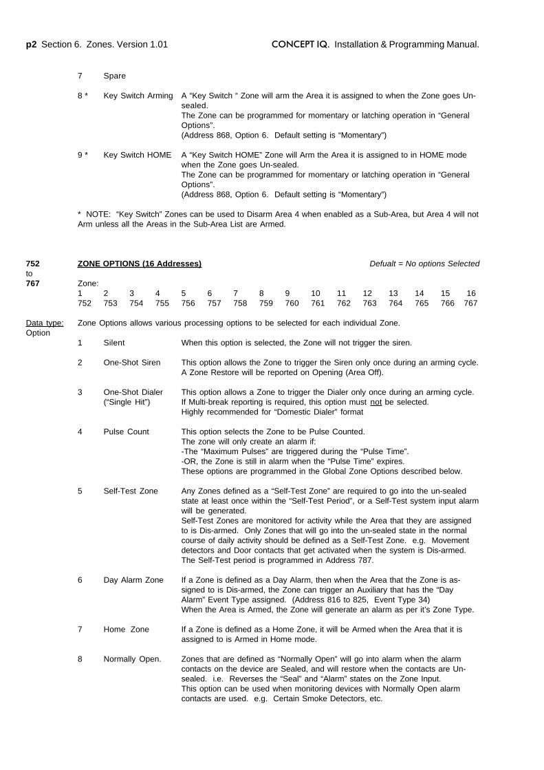
p2 Section 6. Zones. Version 1.01 CONCEPT IQ. Installation & Programming Manual.
7 Spare
8 * Key Switch Arming A “Key Switch “ Zone will arm the Area it is assigned to when the Zone goes Un-sealed.The Zone can be programmed for momentary or latching operation in “GeneralOptions”.(Address 868, Option 6. Default setting is “Momentary”)
9 * Key Switch HOME A “Key Switch HOME” Zone will Arm the Area it is assigned to in HOME modewhen the Zone goes Un-sealed.The Zone can be programmed for momentary or latching operation in “GeneralOptions”.(Address 868, Option 6. Default setting is “Momentary”)
* NOTE: “Key Switch” Zones can be used to Disarm Area 4 when enabled as a Sub-Area, but Area 4 will notArm unless all the Areas in the Sub-Area List are Armed.
ZONE OPTIONS (16 Addresses) Defualt = No options Selected
Zone:1 2 3 4 5 6 7 8 9 10 11 12 13 14 15 16752 753 754 755 756 757 758 759 760 761 762 763 764 765 766 767
Zone Options allows various processing options to be selected for each individual Zone.
1 Silent When this option is selected, the Zone will not trigger the siren.
2 One-Shot Siren This option allows the Zone to trigger the Siren only once during an arming cycle.A Zone Restore will be reported on Opening (Area Off).
3 One-Shot Dialer This option allows a Zone to trigger the Dialer only once during an arming cycle.(“Single Hit”) If Multi-break reporting is required, this option must not be selected.
Highly recommended for “Domestic Dialer” format
4 Pulse Count This option selects the Zone to be Pulse Counted.The zone will only create an alarm if:-The “Maximum Pulses” are triggered during the “Pulse Time”.-OR, the Zone is still in alarm when the “Pulse Time” expires.These options are programmed in the Global Zone Options described below.
5 Self-Test Zone Any Zones defined as a “Self-Test Zone” are required to go into the un-sealedstate at least once within the “Self-Test Period”, or a Self-Test system input alarmwill be generated.Self-Test Zones are monitored for activity while the Area that they are assignedto is Dis-armed. Only Zones that will go into the un-sealed state in the normalcourse of daily activity should be defined as a Self-Test Zone. e.g. Movementdetectors and Door contacts that get activated when the system is Dis-armed.The Self-Test period is programmed in Address 787.
6 Day Alarm Zone If a Zone is defined as a Day Alarm, then when the Area that the Zone is as-signed to is Dis-armed, the Zone can trigger an Auxiliary that has the “DayAlarm” Event Type assigned. (Address 816 to 825, Event Type 34)When the Area is Armed, the Zone will generate an alarm as per it’s Zone Type.
7 Home Zone If a Zone is defined as a Home Zone, it will be Armed when the Area that it isassigned to is Armed in Home mode.
8 Normally Open. Zones that are defined as “Normally Open” will go into alarm when the alarmcontacts on the device are Sealed, and will restore when the contacts are Un-sealed. i.e. Reverses the “Seal” and “Alarm” states on the Zone Input.This option can be used when monitoring devices with Normally Open alarmcontacts are used. e.g. Certain Smoke Detectors, etc.
752to767
Data type:Option
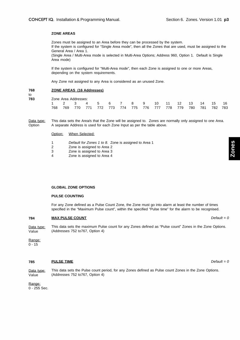
Section 6. Zones. Version 1.01 p3CONCEPT IQ. Installation & Programming Manual.
Zo
nes
ZONE AREAS
Zones must be assigned to an Area before they can be processed by the system.If the system is configured for “Single Area mode”, then all the Zones that are used, must be assigned to theGeneral Area / Area 1.(Single Area / Multi-Area mode is selected in Multi-Area Options; Address 960, Option 1. Default is SingleArea mode)
If the system is configured for “Multi-Area mode”, then each Zone is assigned to one or more Areas,depending on the system requirements.
Any Zone not assigned to any Area is considered as an unused Zone.
ZONE AREAS (16 Addresses)
Zone Area Addresses:1 2 3 4 5 6 7 8 9 10 11 12 13 14 15 16768 769 770 771 772 773 774 775 776 777 778 779 780 781 782 783
This data sets the Area/s that the Zone will be assigned to. Zones are normally only assigned to one Area.A separate Address is used for each Zone Input as per the table above.
Option: When Selected:
1 Default for Zones 1 to 8. Zone is assigned to Area 12 Zone is assigned to Area 23 Zone is assigned to Area 34 Zone is assigned to Area 4
768to783
Data type:Option
784
Data type:Value
Range:0 - 15
785
Data type:Value
Range:0 - 255 Sec.
GLOBAL ZONE OPTIONS
PULSE COUNTING
For any Zone defined as a Pulse Count Zone, the Zone must go into alarm at least the number of timesspecified in the “Maximum Pulse count”, within the specified “Pulse time” for the alarm to be recognised.
MAX PULSE COUNT Default = 0
This data sets the maximum Pulse count for any Zones defined as “Pulse count” Zones in the Zone Options.(Addresses 752 to767, Option 4)
PULSE TIME Default = 0
This data sets the Pulse count period, for any Zones defined as Pulse count Zones in the Zone Options.(Addresses 752 to767, Option 4)

p4 Section 6. Zones. Version 1.01 CONCEPT IQ. Installation & Programming Manual.
END-OF-LINE RESISTOR TYPE
This data sets the value/s of the End-Of-Line (Terminating) resistor/s used for the Zone inputs. This is aglobal setting for all Zone inputs connected to the system.
Single End-Of-Line0 1K1 1K52 2K23 3K3 Default.4 3K95 4K76 5K67 6K88 10K9 12K10 22K
The installation kit provides 1k, 3k3 and 6k8 Resistors. Typical “Terminating Resistor” settings will be:If Single End-Of-Line is used: 3 (3k3)If Dual End-Of-Line is used: 13 (3k3, 6k8)If Zone Doubling is used: 14 (1k, 3k3, 6k8)If the system is replacing another product, and the detectors already have Terminating Resistors of adifferent value, the Terminating Resistors may be retained by choosing the setting that matches theexisting values.
ZONE SELF-TEST PERIOD Default = 0
This data sets the number of arming periods to be included in the Zone Self-Test processing.Any Zone defined as a Self-Test Zone must go un-sealed at least once during this Self-Test period, or aSelf-Test system input alarm will be generated.
A setting from 0 to 16 arming periods can be defined.
Dual End-Of-Line11 2K2, 2K212 2K2, 6K813 3K3, 6K814 Zone Doubling.* 1k, 3k3, 6K815 Zone Doubling.* 1k, 3k3, 6K8 No separate tamper state.
*NOTE: The “Zone Doubling” option allows Zones 1 to 8 on theControl Module to support two detection devices on each Zone input.The additional 8 devices will be recognised and processed as Zones 9to 16. Zone Inputs on the plug-on Zone/Auxiliary Expander board willbe ignored.
786
Data type:Value
Range:0 - 15
787
Data type:Value
Range:0 - 16
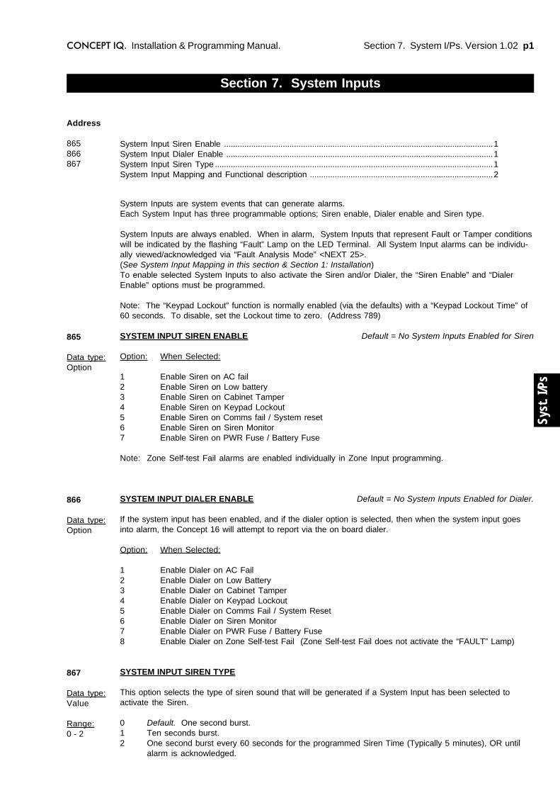
Section 7. System I/Ps. Version 1.02 p1CONCEPT IQ. Installation & Programming Manual.
Syst
. I/P
s
System Inputs are system events that can generate alarms.Each System Input has three programmable options; Siren enable, Dialer enable and Siren type.
System Inputs are always enabled. When in alarm, System Inputs that represent Fault or Tamper conditionswill be indicated by the flashing “Fault” Lamp on the LED Terminal. All System Input alarms can be individu-ally viewed/acknowledged via “Fault Analysis Mode” <NEXT 25>.(See System Input Mapping in this section & Section 1: Installation)To enable selected System Inputs to also activate the Siren and/or Dialer, the “Siren Enable” and “DialerEnable” options must be programmed.
Note: The “Keypad Lockout” function is normally enabled (via the defaults) with a “Keypad Lockout Time” of60 seconds. To disable, set the Lockout time to zero. (Address 789)
SYSTEM INPUT SIREN ENABLE Default = No System Inputs Enabled for Siren
Option: When Selected:
1 Enable Siren on AC fail2 Enable Siren on Low battery3 Enable Siren on Cabinet Tamper4 Enable Siren on Keypad Lockout5 Enable Siren on Comms fail / System reset6 Enable Siren on Siren Monitor7 Enable Siren on PWR Fuse / Battery Fuse
Note: Zone Self-test Fail alarms are enabled individually in Zone Input programming.
SYSTEM INPUT DIALER ENABLE Default = No System Inputs Enabled for Dialer.
If the system input has been enabled, and if the dialer option is selected, then when the system input goesinto alarm, the Concept 16 will attempt to report via the on board dialer.
Option: When Selected:
1 Enable Dialer on AC Fail2 Enable Dialer on Low Battery3 Enable Dialer on Cabinet Tamper4 Enable Dialer on Keypad Lockout5 Enable Dialer on Comms Fail / System Reset6 Enable Dialer on Siren Monitor7 Enable Dialer on PWR Fuse / Battery Fuse8 Enable Dialer on Zone Self-test Fail (Zone Self-test Fail does not activate the “FAULT” Lamp)
SYSTEM INPUT SIREN TYPE
This option selects the type of siren sound that will be generated if a System Input has been selected toactivate the Siren.
0 Default. One second burst.1 Ten seconds burst.2 One second burst every 60 seconds for the programmed Siren Time (Typically 5 minutes), OR until
alarm is acknowledged.
Section 7. System Inputs
System Input Siren Enable .......................................................................................................................1System Input Dialer Enable ......................................................................................................................1System Input Siren Type ...........................................................................................................................1System Input Mapping and Functional description .................................................................................2
Address
865866867
865
Data type:Option
866
Data type:Option
867
Data type:Value
Range:0 - 2

p2 Section 7. System I/Ps. Version 1.02 CONCEPT IQ. Installation & Programming Manual.
SYSTEM INPUT MAPPING AND FUNCTIONAL DESCRIPTION
System Inputs are mapped to the Input Numbers shown in the following table.
NOTES:1) If the Siren output is not used, or a High impedance device is connected (e.g. Piezo siren), a 6k8 resistor must be
installed across the Siren output to prevent the Siren Monitor Alarm from being activated.
2) Period specified by Telecommunications authority requirements.
3) Siren and Dialer operations for Keypad System Input alarms (Medical, Panic, Duress and Fire ) are programmed inthe “Emergency Options” programming. (Address 869)
ALARM INPUTNo.
ZoneLamp
DESCRIPTION
Goes Into Alarm when: Restores when:
AC Fail 101 1 The AC mains has been absent for more than thespecified time period (AC Fail Delay).When the input is in alarm the AC indicator ontheTerminal will flash.
The AC mains is restored.
Low Battery 102 2 The battery voltage falls below 11.2V during Battery Testor while AC supply is not present. (Battery voltage istoo low to provide backup power if AC fails.)
The battery voltage is restored to above11.2V.
Cabinet Tamper 103 3 The Control Panel cabinet cover is removed or thecabinet is removed from it's mounting surface, causingthe Tamper Input to go unsealed.
The Tamper Input is sealed.
Siren Monitor Alarm 104 4 The Siren speaker is disconnected from the ControlPanel. *1
The input will restore when theconnection is restored.
PWR Fuse fail 105 5 Power fuse has blown. (Due to Short circuit or over-current condition.)
The fuse has been replaced.
Battery Fuse fail 106 6 Battery fuse has blown. (Due to Short circuit or over-current condition.)
The fuse has been replaced.
Comms Fail 107 7 System failed to report.Attempts to dial out on both primary and backuptelephone numbers have failed. The system will try todial again after waiting 30 minutes. *2
On the next successful dial.
System Reset 108 8 The Control panel has been reset.
Keypad Lockout 109 9 The System has registered 5 incorrect PIN codeattempts in a row.The system will not allow keypad access for a specifiedperiod of time. (See location KEYPAD LOCKOUT TIMEin the Timer section.)
The lockout period has expired.
Zone Self Test Fail 110 10 Any zone flagged as a self-test zone has failed the self-test criteria. (Does not activate the "FAULT" Lamp)
Alarm has been acknowledged via"Zone Slf Test Display" (NEXT, 26)
Keypad Medical Alarm*3
111 11 Medical Alarm has been activated on a Terminal keypad.
Keypad Panic Alarm*3
112 12 Panic Alarm has been activated on a Terminal keypad.
Keypad Duress Alarm*3
113 13 A Duress PIN code has been entered on a Terminalkeypad.
Keypad Fire Alarm *3 114 14 Fire Alarm has been activated on a Terminal keypad.
Programming Change 115 16 Programming change in system database.
Door Alarm. Door 1. 116
15Door Forced or Door Held condition on specified Door.Note: The system does not differentiate between a DoorForced and Door Held condition.
Door Forced or Door Held conditionrestored on specified Door.
Door Alarm. Door 2. 117
Door Alarm. Door 3. 118
Door Alarm. Door 4. 119
Test Report 120 Automatic (Periodic) or Manual Test Report is triggered.
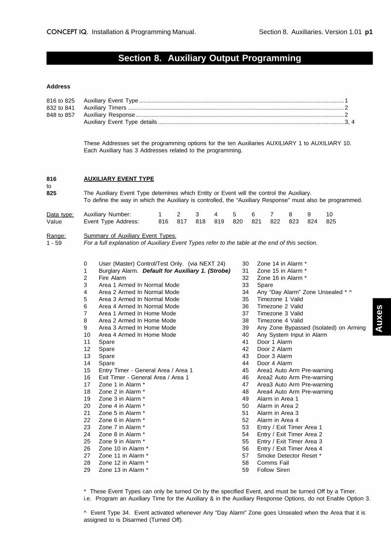
Section 8. Auxiliaries. Version 1.01 p1CONCEPT IQ. Installation & Programming Manual.
Au
xes
0 User (Master) Control/Test Only. (via NEXT 24)1 Burglary Alarm. Default for Auxiliary 1. (Strobe)2 Fire Alarm3 Area 1 Armed In Normal Mode4 Area 2 Armed In Normal Mode5 Area 3 Armed In Normal Mode6 Area 4 Armed In Normal Mode7 Area 1 Armed In Home Mode8 Area 2 Armed In Home Mode9 Area 3 Armed In Home Mode10 Area 4 Armed In Home Mode11 Spare12 Spare13 Spare14 Spare15 Entry Timer - General Area / Area 116 Exit Timer - General Area / Area 117 Zone 1 in Alarm *18 Zone 2 in Alarm *19 Zone 3 in Alarm *20 Zone 4 in Alarm *21 Zone 5 in Alarm *22 Zone 6 in Alarm *23 Zone 7 in Alarm *24 Zone 8 in Alarm *25 Zone 9 in Alarm *26 Zone 10 in Alarm *27 Zone 11 in Alarm *28 Zone 12 in Alarm *29 Zone 13 in Alarm *
Section 8. Auxiliary Output Programming
Auxiliary Event Type ..................................................................................................................................1Auxiliary Timers .........................................................................................................................................2Auxiliary Response ....................................................................................................................................2Auxiliary Event Type details ......................................................................................................................3, 4
These Addresses set the programming options for the ten Auxiliaries AUXILIARY 1 to AUXILIARY 10.Each Auxiliary has 3 Addresses related to the programming.
AUXILIARY EVENT TYPE
The Auxiliary Event Type detemines which Entity or Event will the control the Auxiliary.To define the way in which the Auxiliary is controlled, the “Auxiliary Response” must also be programmed.
Auxiliary Number: 1 2 3 4 5 6 7 8 9 10Event Type Address: 816 817 818 819 820 821 822 823 824 825
Summary of Auxiliary Event Types.For a full explanation of Auxiliary Event Types refer to the table at the end of this section.
Address
816 to 825832 to 841848 to 857
816to825
Data type:Value
Range:1 - 59
30 Zone 14 in Alarm *31 Zone 15 in Alarm *32 Zone 16 in Alarm *33 Spare34 Any “Day Alarm” Zone Unsealed * ^35 Timezone 1 Valid36 Timezone 2 Valid37 Timezone 3 Valid38 Timezone 4 Valid39 Any Zone Bypassed (Isolated) on Arming40 Any System Input in Alarm41 Door 1 Alarm42 Door 2 Alarm43 Door 3 Alarm44 Door 4 Alarm45 Area1 Auto Arm Pre-warning46 Area2 Auto Arm Pre-warning47 Area3 Auto Arm Pre-warning48 Area4 Auto Arm Pre-warning49 Alarm in Area 150 Alarm in Area 251 Alarm in Area 352 Alarm in Area 453 Entry / Exit Timer Area 154 Entry / Exit Timer Area 255 Entry / Exit Timer Area 356 Entry / Exit Timer Area 457 Smoke Detector Reset *58 Comms Fail59 Follow Siren
* These Event Types can only be turned On by the specified Event, and must be turned Off by a Timer.i.e. Program an Auxiliary Time for the Auxiliary & in the Auxiliary Response Options, do not Enable Option 3.
^ Event Type 34. Event activated whenever Any “Day Alarm” Zone goes Unsealed when the Area that it isassigned to is Disarmed (Turned Off).
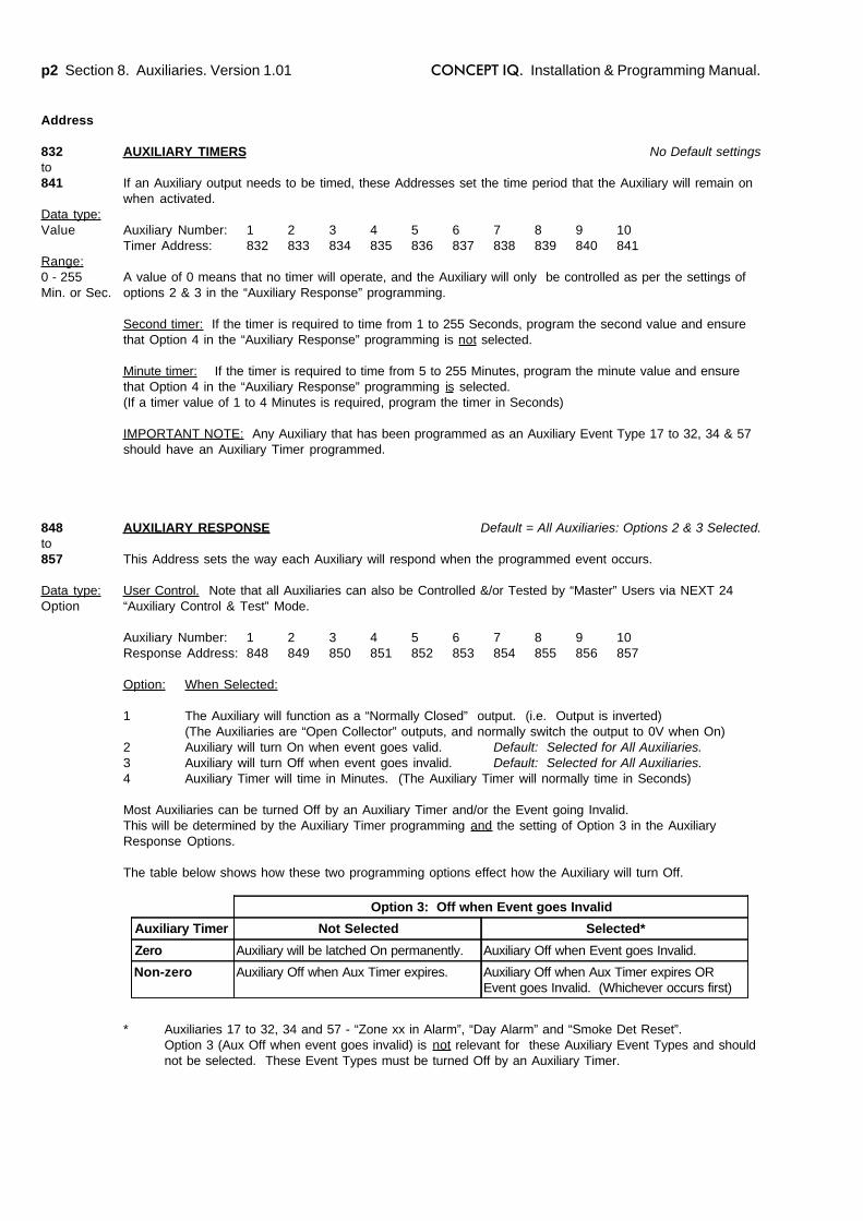
p2 Section 8. Auxiliaries. Version 1.01 CONCEPT IQ. Installation & Programming Manual.
AUXILIARY TIMERS No Default settings
If an Auxiliary output needs to be timed, these Addresses set the time period that the Auxiliary will remain onwhen activated.
Auxiliary Number: 1 2 3 4 5 6 7 8 9 10Timer Address: 832 833 834 835 836 837 838 839 840 841
A value of 0 means that no timer will operate, and the Auxiliary will only be controlled as per the settings ofoptions 2 & 3 in the “Auxiliary Response” programming.
Second timer: If the timer is required to time from 1 to 255 Seconds, program the second value and ensurethat Option 4 in the “Auxiliary Response” programming is not selected.
Minute timer: If the timer is required to time from 5 to 255 Minutes, program the minute value and ensurethat Option 4 in the “Auxiliary Response” programming is selected.(If a timer value of 1 to 4 Minutes is required, program the timer in Seconds)
IMPORTANT NOTE: Any Auxiliary that has been programmed as an Auxiliary Event Type 17 to 32, 34 & 57should have an Auxiliary Timer programmed.
AUXILIARY RESPONSE Default = All Auxiliaries: Options 2 & 3 Selected.
This Address sets the way each Auxiliary will respond when the programmed event occurs.
User Control. Note that all Auxiliaries can also be Controlled &/or Tested by “Master” Users via NEXT 24“Auxiliary Control & Test” Mode.
Auxiliary Number: 1 2 3 4 5 6 7 8 9 10Response Address: 848 849 850 851 852 853 854 855 856 857
Option: When Selected:
1 The Auxiliary will function as a “Normally Closed” output. (i.e. Output is inverted)(The Auxiliaries are “Open Collector” outputs, and normally switch the output to 0V when On)
2 Auxiliary will turn On when event goes valid. Default: Selected for All Auxiliaries.3 Auxiliary will turn Off when event goes invalid. Default: Selected for All Auxiliaries.4 Auxiliary Timer will time in Minutes. (The Auxiliary Timer will normally time in Seconds)
Most Auxiliaries can be turned Off by an Auxiliary Timer and/or the Event going Invalid.This will be determined by the Auxiliary Timer programming and the setting of Option 3 in the AuxiliaryResponse Options.
The table below shows how these two programming options effect how the Auxiliary will turn Off.
* Auxiliaries 17 to 32, 34 and 57 - “Zone xx in Alarm”, “Day Alarm” and “Smoke Det Reset”.Option 3 (Aux Off when event goes invalid) is not relevant for these Auxiliary Event Types and shouldnot be selected. These Event Types must be turned Off by an Auxiliary Timer.
Address
832to841
Data type:Value
Range:0 - 255Min. or Sec.
848to857
Data type:Option
Option 3: Off when Event goes Invalid
Auxiliary Timer Not Selected Selected*
Zero Auxiliary will be latched On permanently. Auxiliary Off when Event goes Invalid.
Non-zero Auxiliary Off when Aux Timer expires. Auxiliary Off when Aux Timer expires OREvent goes Invalid. (Whichever occurs first)
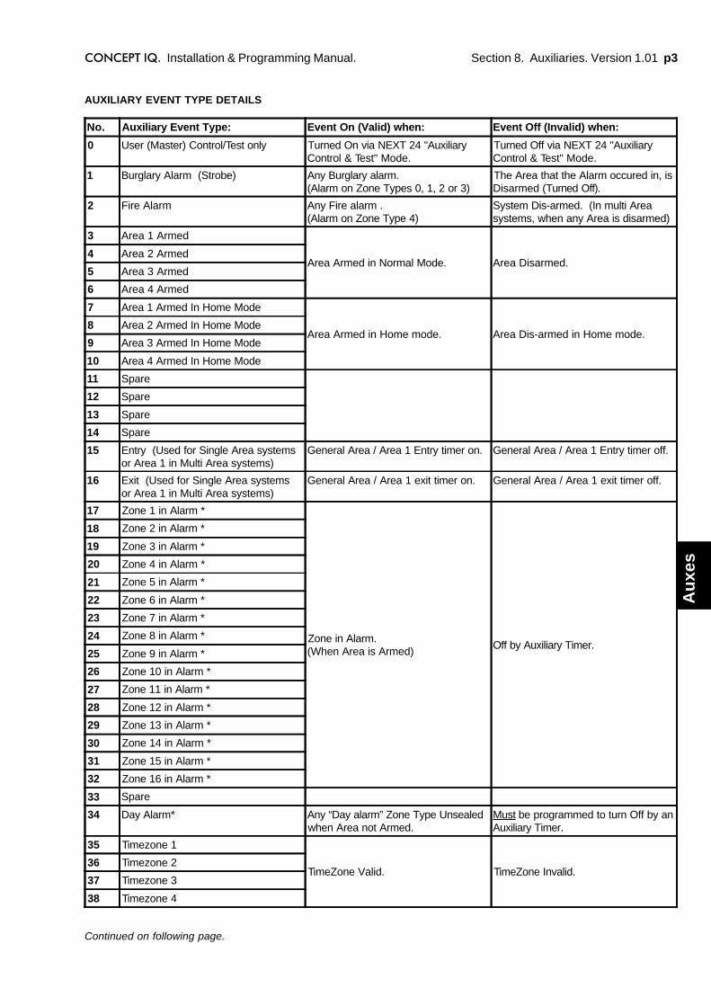
Section 8. Auxiliaries. Version 1.01 p3CONCEPT IQ. Installation & Programming Manual.
Au
xes
AUXILIARY EVENT TYPE DETAILS
Continued on following page.
No. Auxiliary Event Type: Event On (Valid) when: Event Off (Invalid) when:
0 User (Master) Control/Test only Turned On via NEXT 24 "AuxiliaryControl & Test" Mode.
Turned Off via NEXT 24 "AuxiliaryControl & Test" Mode.
1 Burglary Alarm (Strobe) Any Burglary alarm.(Alarm on Zone Types 0, 1, 2 or 3)
The Area that the Alarm occured in, isDisarmed (Turned Off).
2 Fire Alarm Any Fire alarm .(Alarm on Zone Type 4)
System Dis-armed. (In multi Areasystems, when any Area is disarmed)
3 Area 1 Armed
Area Armed in Normal Mode. Area Disarmed.4 Area 2 Armed
5 Area 3 Armed
6 Area 4 Armed
7 Area 1 Armed In Home Mode
Area Armed in Home mode. Area Dis-armed in Home mode.8 Area 2 Armed In Home Mode
9 Area 3 Armed In Home Mode
10 Area 4 Armed In Home Mode
11 Spare
12 Spare
13 Spare
14 Spare
15 Entry (Used for Single Area systemsor Area 1 in Multi Area systems)
General Area / Area 1 Entry timer on. General Area / Area 1 Entry timer off.
16 Exit (Used for Single Area systemsor Area 1 in Multi Area systems)
General Area / Area 1 exit timer on. General Area / Area 1 exit timer off.
17 Zone 1 in Alarm *
Zone in Alarm.(When Area is Armed)
Off by Auxiliary Timer.
18 Zone 2 in Alarm *
19 Zone 3 in Alarm *
20 Zone 4 in Alarm *
21 Zone 5 in Alarm *
22 Zone 6 in Alarm *
23 Zone 7 in Alarm *
24 Zone 8 in Alarm *
25 Zone 9 in Alarm *
26 Zone 10 in Alarm *
27 Zone 11 in Alarm *
28 Zone 12 in Alarm *
29 Zone 13 in Alarm *
30 Zone 14 in Alarm *
31 Zone 15 in Alarm *
32 Zone 16 in Alarm *
33 Spare
34 Day Alarm* Any “Day alarm” Zone Type Unsealedwhen Area not Armed.
Must be programmed to turn Off by anAuxiliary Timer.
35 Timezone 1
TimeZone Valid. TimeZone Invalid.36 Timezone 2
37 Timezone 3
38 Timezone 4

p4 Section 8. Auxiliaries. Version 1.01 CONCEPT IQ. Installation & Programming Manual.
AUXILIARY EVENT TYPE DETAILS
* Auxiliaries 17 to 34 and 57 - “Zone xx Unsealed”, “Door Bell”, “Day Alarm” and “Smoke Det Reset”.Option 3 (Aux Off when event goes invalid) is not relevant for these Auxiliary Event Types and should not beselected. These Event Types must be turned Off by an Auxiliary Timer.
No. Auxiliary Event Type: Event On (Valid) when: Event Off (Invalid) when:
39 Zone Bypassed On Arming Any Zone Bypassed (Isolated) onarming.
Any Area turned off.
40 System Alarm Any system input in alarm. System input acknowledged and nosystem input remaining in alarm.
41 Door 1 Alarm
Door Forced or Door Held Alarm onthe specified Door.
Door Forced or Door Held Restoredon the specified Door.
42 Door 2 Alarm
43 Door 3 Alarm
44 Door 4 Alarm
45 Area 1 Auto Arm PrewarnAuto-Arm Pre-warn started in thespecified Area. (Pre-warn timerprogrammed in Address 870)
Auto-Arm Pre-warning expired.(Area on)
46 Area 2 Auto Arm Prewarn
47 Area 3 Auto Arm Prewarn
48 Area 4 Auto Arm Prewarn
49 Alarm. General Area / Area1
Any Alarm in the specified Area. Area Disarmed.50 Alarm. Area 2
51 Alarm. Area 3
52 Alarm. Area 4
53 Entry / Exit. General Area / Area 1
Entry or Exit timer running in thespecified Area.
Entry or Exit timer cancelled orexpired in Area.
54 Entry / Exit. Area 2
55 Entry / Exit. Area 3
56 Entry / Exit. Area 4
57 Smoke Detector Reset * "Smoke Detector Reset" operation isperformed at a Terminal.PIN code, <NEXT>, 99.(User must have "Master" User Type)
Must be programmed to turn Off by anAuxiliary Timer.
58 Comms Fail System failed to report. On the next successful dial.
59 Siren Siren active. Siren off.
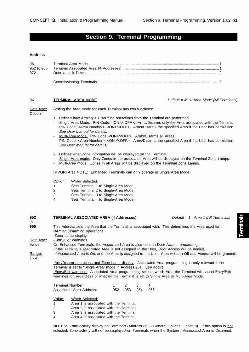
Section 9. Terminal Programming. Version 1.02 p1CONCEPT IQ. Installation & Programming Manual.
Term
inal
s
Section 9. Terminal Programming
Terminal Area Mode ..................................................................................................................................1Terminal Associated Area (4 Addresses) ................................................................................................1Door Unlock Time ......................................................................................................................................2
Commissioning Terminals .........................................................................................................................2
TERMINAL AREA MODE Default = Multi-Area Mode (All Terminals)
Setting the Area mode for each Terminal has two functions:
1. Defines how Arming & Disarming operations from the Terminal are performed.- Single Area Mode: PIN Code, <ON>/<OFF>; Arms/Disarms only the Area associated with the Terminal.
PIN Code, <Area Number>, <ON>/<OFF>; Arms/Disarms the specified Area if the User has permission.See User manual for details.
- Multi-Area Mode: PIN Code, <ON>/<OFF>; Arms/Disarms all Areas.PIN Code, <Area Number>, <ON>/<OFF>; Arms/Disarms the specified Area if the User has permission.See User manual for details.
2. Defines what Zone information will be displayed on the Terminal.- Single Area mode: Only Zones in the associated Area will be displayed on the Terminal Zone Lamps.- Multi-Area mode: Zones in all Areas will be displayed on the Terminal Zone Lamps.
IMPORTANT NOTE: Enhanced Terminals can only operate in Single Area Mode.
Option: When Selected:1 Sets Terminal 1 to Single-Area Mode.2 Sets Terminal 2 to Single-Area Mode.3 Sets Terminal 3 to Single-Area Mode.4 Sets Terminal 4 to Single-Area Mode.
TERMINAL ASSOCIATED AREA (4 Addresses) Default = 1: Area 1 (All Terminals)
This Address sets the Area that the Terminal is associated with. This determines the Area used for:-Arming/Disarming operations.-Zone Lamp display.-Entry/Exit warnings.On Enhanced Terminals, the Associated Area is also used in Door Access processing.-If the Terminal’s Associated Area is not assigned to the User, Door Access will be denied.-If Associated Area is On, and the Area is assigned to the User, Area will turn Off and Access will be granted.
-Arm/Disarm operations and Zone Lamp display: Associated Area programming is only relevant if theTerminal is set to “Single Area” mode in Address 961. See above.-Entry/Exit warnings: Associated Area programming selects which Area the Terminal will sound Entry/Exitwarnings for, regardless of whether the Terminal is set to Single Area or Multi-Area Mode.
Terminal Number: 1 2 3 4Associated Area Address: 952 953 954 955
Value: When Selected:1 Area 1 is associated with the Terminal.2 Area 2 is associated with the Terminal.3 Area 3 is associated with the Terminal.4 Area 4 is associated with the Terminal.
NOTES: Zone activity display on Terminals (Address 868 - General Options, Option 8). If this option is notselected, Zone activity will not be displayed on Terminals when the System / Associated Area is Disarmed.
Address
961952 to 955872
961
Data type:Option
952to955
Data type:Value
Range:1 - 4

p2 Section 9. Terminal Programming. Version 1.02 CONCEPT IQ. Installation & Programming Manual.
COMMISSIONING THE TERMINALS
1. Enable Terminal Configuration Mode.Method 1: Remove power from the Terminal.
Hold down the <NEXT> and <HOME> keys.Re-apply power to the Terminal.Release the <NEXT> and <HOME> keys.
Method 2: Hold down the <NEXT> and <HOME> keys.Short the “RST” (Reset) link on the rear of the Terminal.Release the <NEXT> and <HOME> keys.
2. Note the current Address setting.The current Address of the Terminal will be displayed via the Zone 1 to 4 Lamps.The Zone Lamp number that corresponds to the current Address will flash.
3. Select the new Terminal Address number.Press the key that corresponds to the required Address (1 to 4) within 10 seconds, then press <ENTER>.
When the <ENTER> key is pressed, a Standard Terminal will now exit Terminal Configuration Mode.
4. Note the current Door Alarm enable status. ENHANCED TERMINALS ONLY.After the Terminal Address has been entered as per Step 3, the display will now show the current Door Alarm enablestatus: 0 = Disabled (Default)
1 = Enabled
5. Enable / Disable Door Alarm. ENHANCED TERMINALS ONLY.If an Enhanced Terminal is required to generate the Door Alarm to indicate a “Door Forced” or “Door Held” condition,then “Door Alarm” must be enabled for that Terminal.
To Enable or Disable, select the option required (0 or 1) within 10 seconds, then press <ENTER>.
When the <ENTER> key is pressed, the Enhanced Terminal will now exit Terminal Configuration Mode.
6. Initialize the LAN.When all Terminals are configured and connected to the Control Module via the system LAN, the LAN must beinitialized by Removing and Re-applying power to the Control Module.Remember to disconnect the battery also when removing power.NOTE: Not required if Terminals are commissioned before the “CLK” and “DATA” wires are connected to the ControlModule.
DOOR UNLOCK TIME Default = 5 Seconds (All Terminals)
Relevant to Enhanced Terminals only.This Address sets the time that the Lock Auxiliary output on the Enhanced Terminals will remain on, to unlockthe associated Door.
ACCESS CONTROL NOTES:1) MAXIMUM DOOR OPEN TIME. The Maximum Door Open Time is 4 x Unlock time.e.g. If the Door Unlock time is 5 Seconds, the Maximum Door Open Time will be 20 Seconds.
2) DOOR ALARMS:-DOOR HELD (DOTL). If the Door Reed input on the Enhanced Terminal remains un-sealed for longer thanthe Maximum Door Open time after a valid Door Access event, a Door Alarm will be generated for that Door.
-DOOR FORCED. If the Door Reed input on the Enhanced Terminal goes un-sealed without a valid DoorAccess event, a Door Alarm will be generated for that Door.
-The system does not differentiate whether a Door Alarm is caused by a “Door Held (DOTL) or “Door Forced”condition.
5) DOOR RE-LOCK.If the Door Reed switch is connected to Zone 2 on the Enhanced Terminal, the system monitors the state ofthe Door (Opened or Closed), and detects when the Door is opened after being un-locked.This allows the system to cancel the Lock Auxiliary (“Clip” the Door Unlock Time) as soon as the Door isopened, ensuring that the Door is re-locked when it closes, and preventing Door “bounce”.
872
Data type:Value
Range:0 - 60 Sec.
Section 10. Comms. Version 1.01 p1CONCEPT IQ. Installation & Programming Manual.
Co
mm
s
TELEPHONE NUMBERS
When the system is required to report to a Central Station or a Telephone,OR the system is required to Callback a PC that is dialing in for Remote connection, you will be required toprogram one or more Telephone numbers.
Telephone numbers are programmed as a Sequential number of up to 16 digits using the keys shown in thefollowing table.
e.g. Telephone number: 1 Pause 1234 5678 is entered by the key sequence:<*>, 1, <NEXT>, 1, 2, 3, 4, 5, 6, 7, 8, <ENTER>
Telephone number selection.Remember that only the Start Address is selected for programming Telephone numbers; and that <#>, <#>,cannot be used to move on to the next Address when programming sequential numbers.
Quick Telephone number selection. When programming Telephone numbers, Press <HOME> to move on tothe next Telephone number to program.If you are programming more than one telephone number, this eliminates the need to select the Address ofthe next number to program.The Telephone numbers are presented in the sequence: Primary Number, Secondary number, Callbacknumber. e.g. If the Secondary number has been programmed, pressing <HOME> will move on to theCallback number, and pressing <HOME> again will jump back to the Primary number.
Section 10. Communications
Communications programming sets all the parameters and options for:-Contact ID or Domestic Dialer reporting.-Dialer Test reporting.-Remote Dial-up connection.-Serial Port communications.
DialerTelephone numbers .......................................................................................................................1Primary telephone number (15 Addresses) ...............................................................................2Secondary telephone number (15 Addresses) ...........................................................................2Call back telephone number (15 Addresses) ............................................................................2Reporting format ............................................................................................................................2Dialer options .................................................................................................................................2Maximum attempts ........................................................................................................................2
Test reportingTest report period ..........................................................................................................................3Test report hour .............................................................................................................................3Test report minute ..........................................................................................................................3
Remote connectRemote connect options ...............................................................................................................3Rings to answer .............................................................................................................................3Answer machine bypass ...............................................................................................................3
Serial Port OptionsPort 0 Communications Task ........................................................................................................4Port 0 Baud rate .............................................................................................................................4
Client CodesGeneral Area / Area 1 Client Code (4 Addresses) .....................................................................4Area 2 Client Code (4 Addresses) ...............................................................................................4Area 3 Client Code (4 Addresses) ...............................................................................................4Area 4 Client Code (4 Addresses) ...............................................................................................4
Contact ID Event Codes ............................................................................................................................5
Address
163264484950
515253
548081
8283
896900904908
Telephone number digit to program: 0 to 9 # * Pause (1 Second)
Key to Press on LED Terminal keypad: <0> to <9> <#> <*> <NEXT>
Value displayed on Zone Lamps: 0 to 9 10 11 12
p2 Section 10. Comms. Version 1.01 CONCEPT IQ. Installation & Programming Manual.
Address
16
Data type:Value
Range:0 - 12
32
Data type:Value
Range:0 - 12
64
Data type:Value
Range:0 - 12
48
Data type:Value
Range:0 - 2
PRIMARY TELEPHONE NUMBER. (16 Addresses)
When the system is required to report to a Central Station or a Telephone, this is the first Telephone numberthe Control Module will dial.
SECONDARY TELEPHONE NUMBER. (16 Addresses)
If the Primary Telephone number fails, the dialer will then try the Secondary Telephone number. If this failsthe dialer will alternate between the two numbers until the “Maximum Attempts“ (Address 50) are reached.
CALL BACK TELEPHONE NUMBER. (16 Addresses)
This Address sets the Telephone number that the system will use when dialing back the computer.
The “Remote connect with Callback” option must be selected. (Address 54. Select option 2)
REPORTING FORMAT Default = 0. (No Dialer)
This Address selects the reporting format that the system will use if reporting via the dialer.
0 No dialer. Default. When option is selected the system will not report through its on boarddialer. It will operate in local mode.
1 Contact ID. Reports alarm information in Ademco Contact ID format.2 Domestic. Domestic dialing enables the Control Module to send an audible tone to a private
telephone number to warn the owner of activity at the premises.
NOTES: “Domestic” Dialer format.
When the alarm signal is received by the remote Telephone, the Telephone User will hear:- Beeps of the same tone to indicate an Area Opening or Closing event.- Beeps of 2 different tones to indicate an Alarm Event.
The alarm is acknowledged by the receiving telephone answering the call.
The Telephone User does not have to perform any operation to acknowledge the alarm.Once the alarm signal is heard, the User can simply hang-up the telephone.
IMPORTANT NOTE:-Once the receiving telephone has answered the call, the alarm message is regarded as being acknowledgedand will not be sent again, regardless of whether a User has heard the alarm signal or not.-This means that if an Answering Machine, Fax machine or similar device answers the call, the alarm will stillbe regarded as being acknowledged.-If this feature is used, care must be excercised in selecting appropriate telephone numbers to ensure that thealarm signal will be heard by an appropriate User.
Section 10. Comms. Version 1.01 p3CONCEPT IQ. Installation & Programming Manual.
Co
mm
s
DIALER OPTIONS Default = No options selected.
Dialer options allow various reporting and remote control options to be selected.The Installer can select the different types of messages that are to be sent to a remote Central MonitoringStation (Base station), or to a Telephone; and whether DTMF remote control is allowed.Depending on the customer requirements, any or all of the message types, 1 to 5, listed below can betransmitted:
Option: When selected:1 Alarms are reported via Dialer.2 Restorals are reported via Dialer.3 Area Openings / Closings (Area Offs / Ons) are reported via Dialer.4 Programming changes are reported via Dialer.5 Opening reports will only be sent if an alarm has occurred in the previous Armed period.6 Remote control with DTMF Card is enabled. NOTE: While a remote telephone has connected to
the system to perform DTMF remote control functions, Upload/download via the dialer istemporarily disabled.
7 Isolates are reported via Dialer.
IMPORTANT NOTE: Do not select any options 1 to 5, unless a Dialer Reporting format has been selected.
MAXIMUM DIAL ATTEMPTS Default = 10 Attempts.
This Address sets the maximum number of dialing attempts the system can make to contact the CentralMonitoring Station or Domestic Telephone.
The system will alternate betwen the Primary and Secondary Telephone numbers for each attempt.This setting represents the total number of attempts on both Telephone numbers.
IMPORTANT NOTE: Regulatory authorities may limit this number. (In Australia, ACA specify a maximum of10 attempts. ACA Approval will be void if Max Attempts is set to a higher value)
When the maximum number of attempts has been reached, and no connection is made, the Comms FailSystem Input will be activated. The system will wait 30 minutes before attempting to dial again. (This waitperiod is a regulatory requirement)
TEST REPORTING
The following Addresses set the frequency of automatic Test reports and the time of day the Test Report is tobe sent to the Central Station.
Test report period
This option sets the frequency of the automatic Test Report. (i.e. How often a Test Report will be sent)
Data: When selected:0 Default. No Test Report will be sent.1 Test Report sent every day.2 Test Report sent every Monday.3 Test Report sent on the first day of every month.
Test report hour
This Address sets the hour that the test report will be sent.
Address
49
Data type:Option
50
Data type:Value
Range:1 - 16 calls
Data type:Value
51
Range:0 -3
52
Range:0 -23 (hour)
p4 Section 10. Comms. Version 1.01 CONCEPT IQ. Installation & Programming Manual.
Test report minute
This Address sets the minute the test report will be sent.
e.g. If: The “Test Report period” option is set to 2,the “Test Report Hour” is set to 22, and the “Test Report Minute” is set to 45.Then a Test Report will be sent to the Central Station at 10:45 PM every Monday.
REMOTE CONNECT
These options allow the Installer to program various parameters relating to remote connection for Upload/Download and/or DTMF Telephone remote control.
Remote connect options
This Address sets the remote connect method for programming the system with the Upload / Downloadsoftware. Remote connect for DTMF Telephone remote control is not affected by this setting.
Data: When selected:0 Default. Remote connect not allowed1 Remote connect enabled. (Without callback)2 Remote connect enabled with Callback.
Rings to answer Default = 16 Rings.
This Address sets the number of rings before the system will answer an incoming call.This setting is relevant to both Upload/Download connection and DTMF remote control connection.
Answering machine (Fax) bypass “Follow-on” time.
This feature is used when Upload/Download software or DTMF Telephone is trying to remotely connect to thesystem, and an Answering Machine is connected to the same Telephone line. If this feature is enabled, theremote device must call the system, then hang up within three rings. If the remote device calls the systemagain within the programmed “Follow-on” time then the system will answer the call on the first ring & connect.
Data: When selected:0 Default. Answering Machine Bypass disabled1 Follow-on time = 10 secs2 Follow-on time = 30 secs3 Follow-on time = 60 secs
SERIAL PORT OPTIONS
Serial Port options allow the Installer to program the Communications Task and Baud rate for the Serial Porton the Control Module.
Port 0 Communications Task
Data: When selected:0 Default. Serial Port not used.1 Securitel STU. (Not yet available)2 Serial Printer. (Not yet available)3 Upload / Download. (Requires the Serial Adapter Cable)
NOTE: While Upload/Download software is connected and communicating with the Control Module, DTMFRemote Control is temporarily disabled.
53
Range:0 -59 (min.)
Data type:Value
54
Range:0 -2
80
Range:1 -16 (rings)
81
Range:0 -3
Data type:Value
82
Range:0 -3
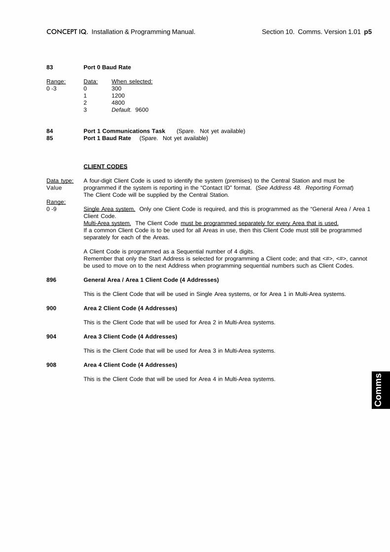
Section 10. Comms. Version 1.01 p5CONCEPT IQ. Installation & Programming Manual.
Co
mm
s
Port 0 Baud Rate
Data: When selected:0 3001 12002 48003 Default. 9600
Port 1 Communications Task (Spare. Not yet available)Port 1 Baud Rate (Spare. Not yet available)
CLIENT CODES
A four-digit Client Code is used to identify the system (premises) to the Central Station and must beprogrammed if the system is reporting in the “Contact ID” format. (See Address 48. Reporting Format)The Client Code will be supplied by the Central Station.
Single Area system. Only one Client Code is required, and this is programmed as the “General Area / Area 1Client Code.Multi-Area system. The Client Code must be programmed separately for every Area that is used.If a common Client Code is to be used for all Areas in use, then this Client Code must still be programmedseparately for each of the Areas.
A Client Code is programmed as a Sequential number of 4 digits.Remember that only the Start Address is selected for programming a Client code; and that <#>, <#>, cannotbe used to move on to the next Address when programming sequential numbers such as Client Codes.
General Area / Area 1 Client Code (4 Addresses)
This is the Client Code that will be used in Single Area systems, or for Area 1 in Multi-Area systems.
Area 2 Client Code (4 Addresses)
This is the Client Code that will be used for Area 2 in Multi-Area systems.
Area 3 Client Code (4 Addresses)
This is the Client Code that will be used for Area 3 in Multi-Area systems.
Area 4 Client Code (4 Addresses)
This is the Client Code that will be used for Area 4 in Multi-Area systems.
83
Range:0 -3
8485
Data type:Value
Range:0 -9
896
900
904
908
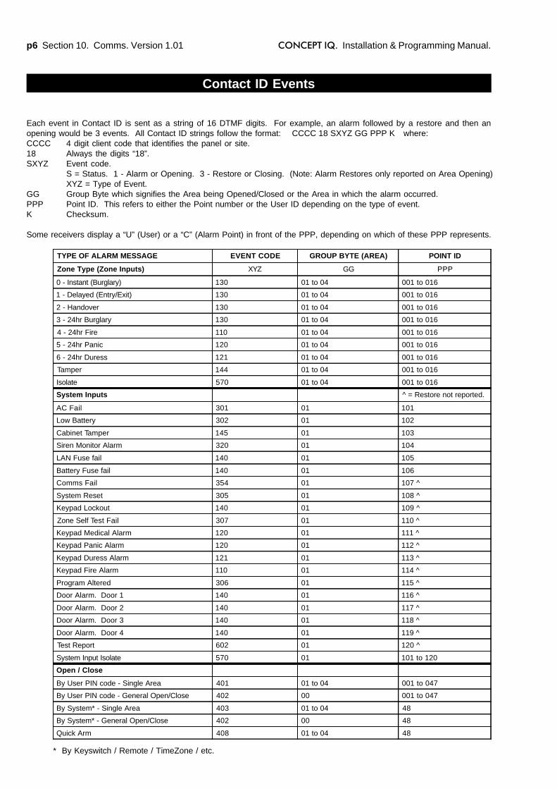
p6 Section 10. Comms. Version 1.01 CONCEPT IQ. Installation & Programming Manual.
Contact ID Events
* By Keyswitch / Remote / TimeZone / etc.
Each event in Contact ID is sent as a string of 16 DTMF digits. For example, an alarm followed by a restore and then anopening would be 3 events. All Contact ID strings follow the format: CCCC 18 SXYZ GG PPP K where:CCCC 4 digit client code that identifies the panel or site.18 Always the digits “18”.SXYZ Event code.
S = Status. 1 - Alarm or Opening. 3 - Restore or Closing. (Note: Alarm Restores only reported on Area Opening)XYZ = Type of Event.
GG Group Byte which signifies the Area being Opened/Closed or the Area in which the alarm occurred.PPP Point ID. This refers to either the Point number or the User ID depending on the type of event.K Checksum.
Some receivers display a “U” (User) or a “C” (Alarm Point) in front of the PPP, depending on which of these PPP represents.
TYPE OF ALARM MESSAGE EVENT CODE GROUP BYTE (AREA) POINT ID
Zone Type (Zone Inputs) XYZ GG PPP
0 - Instant (Burglary) 130 01 to 04 001 to 016
1 - Delayed (Entry/Exit) 130 01 to 04 001 to 016
2 - Handover 130 01 to 04 001 to 016
3 - 24hr Burglary 130 01 to 04 001 to 016
4 - 24hr Fire 110 01 to 04 001 to 016
5 - 24hr Panic 120 01 to 04 001 to 016
6 - 24hr Duress 121 01 to 04 001 to 016
Tamper 144 01 to 04 001 to 016
Isolate 570 01 to 04 001 to 016
System Inputs ^ = Restore not reported.
AC Fail 301 01 101
Low Battery 302 01 102
Cabinet Tamper 145 01 103
Siren Monitor Alarm 320 01 104
LAN Fuse fail 140 01 105
Battery Fuse fail 140 01 106
Comms Fail 354 01 107 ^
System Reset 305 01 108 ^
Keypad Lockout 140 01 109 ^
Zone Self Test Fail 307 01 110 ^
Keypad Medical Alarm 120 01 111 ^
Keypad Panic Alarm 120 01 112 ^
Keypad Duress Alarm 121 01 113 ^
Keypad Fire Alarm 110 01 114 ^
Program Altered 306 01 115 ^
Door Alarm. Door 1 140 01 116 ^
Door Alarm. Door 2 140 01 117 ^
Door Alarm. Door 3 140 01 118 ^
Door Alarm. Door 4 140 01 119 ^
Test Report 602 01 120 ^
System Input Isolate 570 01 101 to 120
Open / Close
By User PIN code - Single Area 401 01 to 04 001 to 047
By User PIN code - General Open/Close 402 00 001 to 047
By System* - Single Area 403 01 to 04 48
By System* - General Open/Close 402 00 48
Quick Arm 408 01 to 04 48
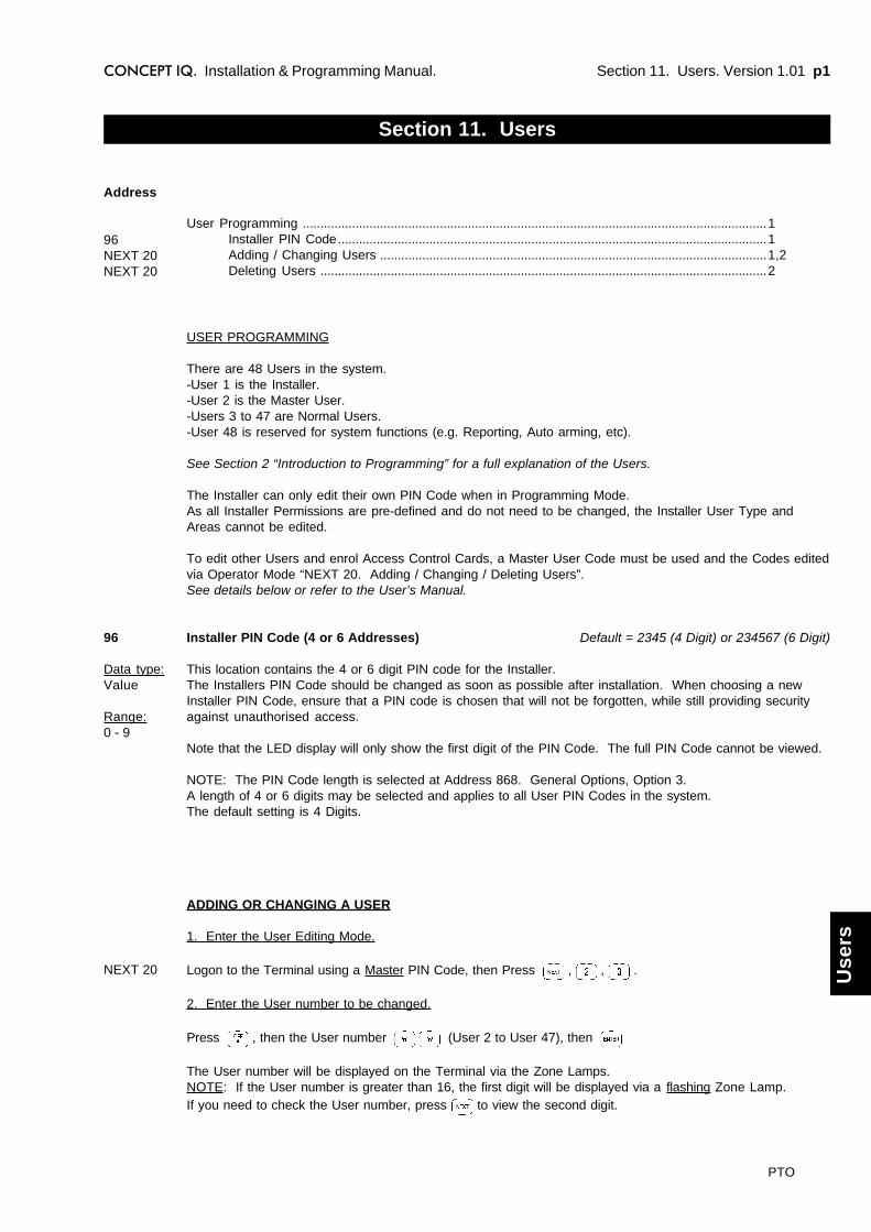
Section 11. Users. Version 1.01 p1CONCEPT IQ. Installation & Programming Manual.
Use
rs
USER PROGRAMMING
There are 48 Users in the system.-User 1 is the Installer.-User 2 is the Master User.-Users 3 to 47 are Normal Users.-User 48 is reserved for system functions (e.g. Reporting, Auto arming, etc).
See Section 2 “Introduction to Programming” for a full explanation of the Users.
The Installer can only edit their own PIN Code when in Programming Mode.As all Installer Permissions are pre-defined and do not need to be changed, the Installer User Type andAreas cannot be edited.
To edit other Users and enrol Access Control Cards, a Master User Code must be used and the Codes editedvia Operator Mode “NEXT 20. Adding / Changing / Deleting Users”.See details below or refer to the User’s Manual.
Installer PIN Code (4 or 6 Addresses) Default = 2345 (4 Digit) or 234567 (6 Digit)
This location contains the 4 or 6 digit PIN code for the Installer.The Installers PIN Code should be changed as soon as possible after installation. When choosing a newInstaller PIN Code, ensure that a PIN code is chosen that will not be forgotten, while still providing securityagainst unauthorised access.
Note that the LED display will only show the first digit of the PIN Code. The full PIN Code cannot be viewed.
NOTE: The PIN Code length is selected at Address 868. General Options, Option 3.A length of 4 or 6 digits may be selected and applies to all User PIN Codes in the system.The default setting is 4 Digits.
Section 11. Users
User Programming ....................................................................................................................................1Installer PIN Code..........................................................................................................................1Adding / Changing Users ..............................................................................................................1,2Deleting Users ...............................................................................................................................2
Address
96NEXT 20NEXT 20
96
Data type:Value
Range:0 - 9
NEXT 20
ADDING OR CHANGING A USER
1. Enter the User Editing Mode.
Logon to the Terminal using a Master PIN Code, then Press , , .
2. Enter the User number to be changed.
Press , then the User number (User 2 to User 47), then
The User number will be displayed on the Terminal via the Zone Lamps.NOTE: If the User number is greater than 16, the first digit will be displayed via a flashing Zone Lamp.If you need to check the User number, press to view the second digit.
PTO

p2 Section 11. Users. Version 1.01 CONCEPT IQ. Installation & Programming Manual.
3. Enrol the User’s Access Card. (If required)
Present the Card at any Access Reader in the system within 30 seconds of selecting the User number.
Three short beeps will sound to confirm that the Card has been enrolled and assigned to the selected User.If the Card is already assigned to another User, or is not recognised by the system, one long beep willindicate a problem.
4. Enter the new PIN Code.
Press , then the new PIN number ... (4 or 6 digits), then
Three short beeps will sound to confirm the PIN number has been programmed. If the PIN is rejected, onelong beep will sound to indicate a problem.
5. Assign the User Type.
Press then Press , then the new User Type number , then
USER TYPE: 0 Arm only Can only Arm the system.1 Arm/Dis-arm Can Arm and Dis-arm the system.2 Arm/Dis-arm/Isolate Can Arm/Dis-arm the system and Isolate Zones.3 Master Can perform all operations above & Master User Operations.
2 beeps will sound to confirm the new User Type has been programmed.
6. Assign the User Area or Areas. (Only required if you have a Multi-Area System)
Press (A long beep will sound if the System is not in Multi-Area mode)
Then for each Area that is to be assigned to this User,Press , then an Area option number , then
OPTION: 0 All Areas De-selected.1 General Area / Area 1 selected. 3 Area 3 selected2 Area 2 selected 4 Area 4 selected
e.g. If Area 1 and Area 3 are to be assigned to the User; Press <*>, 1, <ENTER>; <*>, 3, <ENTER>.
2 beeps will sound to confirm the new Area Option has been selected.
When access control is provided, access is only granted at Door/s associated with the User’s Area/s.
DELETING A USER
1. Enter the User Editing Mode as before.
2. Enter the User number to be changed.
Press , then the User number (User 2 to User 47), then The User number will be displayed on the Terminal.
3. Delete the User.
Press , then to delete the PIN code and/or Card data for this User number.

Section 12. Quick Programming. Version 1.02 p1CONCEPT IQ. Installation & Programming Manual.
How
to E
nter
Dat
a.Se
lect
Add
ress
:Pr
ess
, the
n th
e Ad
dres
s
.. (2
or 3
dig
its),
then
.
N
OTE
: Pr
essi
ng
w
ill ta
ke y
ou to
the
next
Add
ress
.
Ente
r Dat
a:Pr
ess
, the
n th
e ne
w D
ata
..
(1-1
6 di
gits
) OR
Opt
ion
to S
elec
t/De-
sele
ct
, the
n .
N
OTE
: ,
, s
ets
Dat
a/O
ptio
ns to
Fac
tory
Def
ault.
Qu
ick
Pro
g
QU
ICK
PR
OG
RA
MM
ING
GU
IDE
: S
ing
le A
rea
Bu
rgla
ry A
larm
sys
tem
.
1.D
eter
min
e th
e n
um
ber
of
Bu
rgla
ry A
larm
Zo
ne
Inp
uts
th
at w
ill b
e co
nn
ecte
d t
o t
he
syst
em.
For
eas
e of
pro
gram
min
g; I
f E
ntry
/Exi
t Z
ones
are
to
be u
sed,
it is
rec
omm
ende
d th
at:
-The
Zon
e In
put
devi
ce t
hat
will
sta
rt t
he E
ntry
Tim
er is
con
nect
ed t
o Z
one
1.-T
he “
Han
dove
r” Z
one
Inpu
t de
vice
(If
requ
ired)
is c
onne
cted
to
Zon
e 2.
2.L
og
on
to
th
e Te
rmin
al u
sin
g t
he
Inst
alle
r P
IN c
od
e an
d s
elec
t M
OD
E 2
- D
EFA
ULT
ING
TH
E C
ON
TR
OL
MO
DU
LE
.N
EX
T 0
2-E
nter
PIN
, <
NE
XT
>,
0, 2
.S
ectio
n 2.
p7.
3.S
elec
t th
e D
efau
lt O
pti
on
th
at m
atch
es t
he
nu
mb
er o
f B
urg
lary
Ala
rm Z
on
e In
pu
ts r
equ
ired
.-<
*>,
nn,
<E
NT
ER
>.
Whe
re “
nn”
is t
he D
efau
lt op
tion.
0
= N
o Z
ones
, 1
= 1
Zon
e, 8
= 8
Zon
es,
etc.
NO
TE
: D
efau
lt Z
one
Type
s:
Zon
e 1
= 1
-Del
ayed
(E
ntry
/Exi
t);
Z
one
2 =
2-H
ando
ver;
Zon
es 3
to
16 =
0-I
nsta
nt.
If th
e D
efau
lt Z
one
Type
s ne
ed t
o be
cha
nged
, pr
ogra
m t
he n
ew Z
one
Type
in A
ddre
sses
736
(Z
one
1) t
o 75
1 (Z
one
16)
En
ter
Pro
gra
mm
ing
Mo
de
(Mo
de
01)
to p
rog
ram
ad
dit
ion
al o
pti
on
s &
dat
a.N
EX
T 0
1-E
nter
PIN
, <
NE
XT
>,
0, 1
.
4.IF
th
e E
nd
-of-
Lin
e R
esis
tors
are
a v
alu
e o
ther
th
an “
3k3
Sin
gle
En
d-o
f-L
ine”
:A
dd
ress
786
.P
rogr
am t
he “
End
-of-
Line
Res
isto
r” V
alue
.S
ectio
n 6.
p4.
EN
D-O
F-L
INE
RE
SIS
TO
R T
YP
ES
:S
ingl
e E
OL:
0 -1
k /
1 -
1k5
/
2 -2
k2
/ 3
-3k
3 /
4
-3k9
/
5 -
4k7
/
6 -5
k6
/ 7
-6k
8 /
8 -
10k
/ 9
-12
k /
10 -
22k
Dua
l E
OL:
11 -
2k2,
2k2
tam
per
/
12 -
2k2,
6k8
tam
per
/
13 -
3k3,
6k8
tam
per
Zon
e D
oube
d:14
-1k
, 3k
3, 6
k8 z
one
doub
led
/
15 -
1k,
3k3,
6k8
zon
e do
uble
d (n
o se
pera
te t
ampe
r st
ate)
5.E
nab
le t
he
Sys
tem
In
pu
ts t
hat
are
req
uir
ed t
o a
ctiv
ate
the
Sir
en.
Ad
dre
ss 8
65.
1 -
AC
Fai
l.4
- K
eypa
d Lo
ckou
t.6
- S
iren
Mon
itor.
Sec
tion
7. p
1.2
- Lo
w B
atte
ry.
5 -
Com
ms
Fai
l / S
yste
m R
eset
.7
- P
WR
Fus
e /
Bat
tery
Fus
e.3
- C
abin
et T
ampe
r.N
OT
E:
If
any
of t
hese
opt
ions
are
sel
ecte
d, c
heck
the
“S
yste
m I
nput
Sire
n Ty
pe”
setti
ng.
Add
ress
867
.0
= 1
sec
ond
burs
t (D
efau
lt).
1 =
10
seco
nd b
urst
.2
= 1
Sec
bur
st e
very
60
Sec
s fo
r 5
Min
s.
6.E
nab
le t
he
Sys
tem
In
pu
ts t
hat
are
req
uir
ed t
o a
ctiv
ate
the
Dia
ler.
Ad
dre
ss 8
66.
1 -
AC
Fai
l.4
- K
eypa
d Lo
ckou
t.7
- P
WR
Fus
e /
Bat
tery
Fus
e.S
ectio
n 7.
p1.
2 -
Low
Bat
tery
.5
- C
omm
s F
ail /
Sys
tem
Res
et.
8 -
Zon
e S
elf-
Test
Fai
l.3
- C
abin
et T
ampe
r.6
- S
iren
Mon
itor.
Section 12. Quick Programming & Database Record sheets.

p2 Section 12. Quick Programming. Version 1.02 CONCEPT IQ. Installation & Programming Manual.7.
En
able
an
y ad
dit
ion
al G
ener
al S
yste
m O
pti
on
s th
at a
re r
equ
ired
.A
dd
ress
868
1 ^
Aut
o-Is
olat
e on
Arm
ing.
4 *
Clo
ck s
ync.
to
50H
z A
C M
ains
.7
Allo
w M
aste
r U
sers
to
edit
Tele
phon
e nu
mbe
rs.
Sec
tion
3. p
1.2
Qui
ck A
rmin
g.5
^ A
utom
atic
Bat
tery
Tes
ting.
8 *
Dis
play
Zon
e ac
tivity
whe
n di
sarm
ed.
3 6
dig
it P
IN c
odes
.6
“La
tchi
ng”
Key
-sw
itch
oper
atio
n.^
Rec
omm
ende
d.*
Alre
ady
enab
led
by d
efau
lt.
8.P
rog
ram
cu
rren
t Ti
me
and
Dat
e.N
EX
T 2
3S
et t
he R
eal-T
ime
Clo
ck.
Sec
tion
4. p
4.T
he d
ate
and
time
are
stor
ed in
the
fol
low
ing
orde
r:
mm
:hh
; D
D:M
M:Y
Y ;
di.e
. M
inut
e, M
inut
e;
Hou
r, H
our;
D
ay,
Day
;
Mon
th,
Mon
th;
Ye
ar,
Yea
r;
Day
Of
Wee
k:
(Sun
day
= 1
)e.
g.1)
07
:24
AM
, M
onda
y, J
une
5, 2
001
2,4,
0,7,
0,5,
0,6,
0,1,
2, <
EN
TE
R>
2)
05:1
5 P
M,
Thu
rsda
y, S
epte
mbe
r 20
, 20
011,
5,1,
7,2,
0,0,
9,0,
1,5,
<E
NT
ER
>
9.IF
th
e sy
stem
is
to r
epo
rt i
n C
on
tact
ID
or
Do
mes
tic
Dia
ler
form
ats,
pro
gra
m t
he
Dia
ler
op
tio
ns.
-Pro
gram
the
Prim
ary
& S
econ
dary
Tel
epho
ne n
umbe
rs.
Ad
dre
sses
16
& 3
2.S
ectio
n 10
. p1
& 2
.-S
elec
t th
e R
epor
ting
For
mat
.1
= C
onta
ct I
D.
2 =
Dom
estic
*A
dd
ress
48.
(* D
TM
F C
ard
mus
t be
fitt
ed t
o C
ontr
ol M
odul
e)S
ectio
n 10
. p2
.
-Sel
ect
the
requ
ired
Dia
ler
Opt
ions
.A
dd
ress
49.
1 -
Ala
rms
repo
rted
via
Dia
ler.
4 -
Pro
g. c
hang
e re
port
ed v
ia D
iale
r.6
- R
emot
e co
ntro
l via
DT
MF
Car
d en
able
d.*
2 -
Res
tore
s re
port
ed v
ia D
iale
r.5
- R
epor
t O
pen
only
afte
r an
ala
rm.
7 -
Isol
ates
rep
orte
d vi
a D
iale
r.3
- A
rea
Ope
n/C
lose
rep
orte
d vi
a D
iale
r.
-Pro
gram
the
Are
a 1
Clie
nt C
ode.
(4
Dig
its -
supp
lied
by t
he C
entr
al M
onito
ring
Sta
tion)
Ad
dre
ss 8
96.
Sec
tion
10.
p5.
10.
IF p
erio
dic
Tes
t R
epo
rts
are
to b
e se
nt
to t
he
Cen
tral
Mo
nit
ori
ng
Sta
tio
n,
pro
gra
m t
he
Test
Rep
ort
op
tio
ns.
Ad
dre
ss 5
1.-P
rogr
am t
he T
est
Rep
ort
perio
d.S
ectio
n 10
. p3
.0
- N
o Te
st R
epor
t.1
- E
very
Day
.2
- E
very
Mon
day.
3 -
Firs
t da
y of
eve
ry M
onth
.
-Pro
gram
the
tim
e of
day
the
Tes
t R
epor
t is
to
be s
ent.
Ad
dre
ss 5
2:
Ho
ur.
Ad
dre
ss 5
3:
Min
.S
ectio
n 10
. p3
.
11.
IF R
emo
te c
on
nec
tio
n f
or
Up
load
/Do
wn
load
or
Tele
ph
on
e is
req
uir
ed,
pro
gra
m t
he
Rem
ote
Co
nn
ect
op
tio
ns.
Ad
dre
ss 5
4.E
nabl
e R
emot
e C
onne
ct:
Sel
ect
1 (R
emot
e C
onne
ct a
llow
ed)
Sec
tion
10.
p4.
12.
Ch
ang
e th
e In
stal
ler
PIN
co
de.
Ad
dre
ss 9
6.T
his
shou
ld b
e do
ne b
efor
e th
e sy
stem
is c
omm
issi
oned
and
han
ded
over
to
the
clie
nt.
Sec
tion
11.
p1.
Ens
ure
that
a n
ew P
IN c
ode
is c
hose
n th
at w
ill n
ot b
e fo
rgot
ten,
whi
le s
till p
rovi
ding
sec
urity
aga
inst
una
utho
rised
acc
ess.
13.
Pro
gra
m t
he
Use
rs.
A M
aste
r U
ser
Cod
e m
ust
be u
sed
to p
rogr
am t
he U
sers
. S
ee S
ectio
n 11
: U
sers
, or
the
Use
r’s
Man
ual f
or d
etai
ls.
NE
XT
20
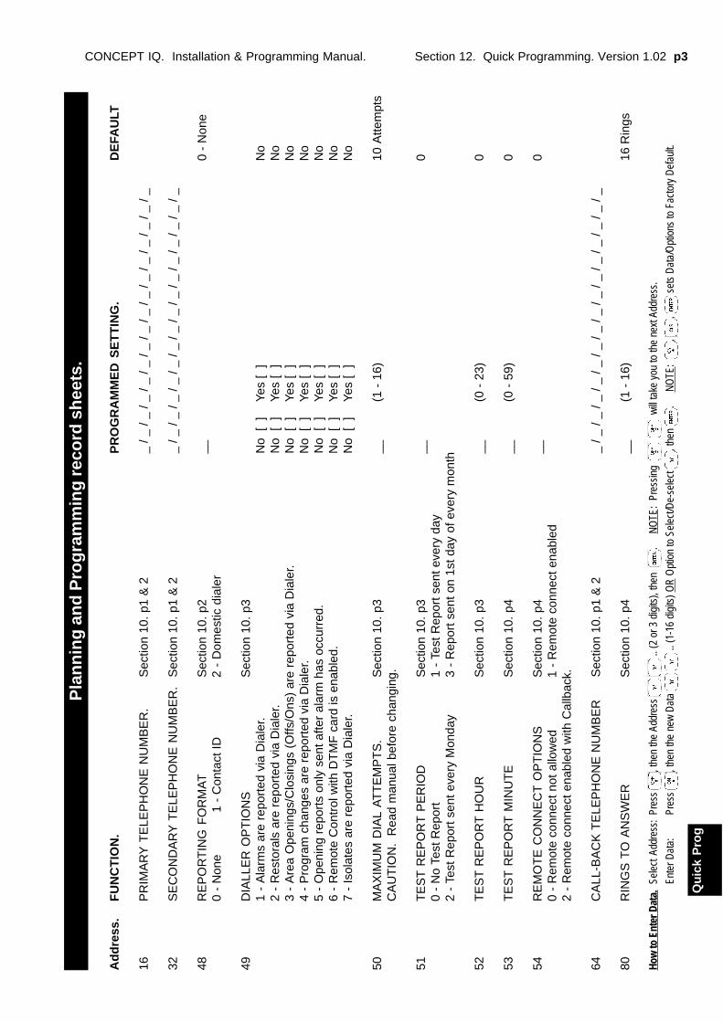
Section 12. Quick Programming. Version 1.02 p3CONCEPT IQ. Installation & Programming Manual.
How
to E
nter
Dat
a.Se
lect
Add
ress
:Pr
ess
, the
n th
e Ad
dres
s
.. (2
or 3
dig
its),
then
.
N
OTE
: Pr
essi
ng
w
ill ta
ke y
ou to
the
next
Add
ress
.
Ente
r Dat
a:Pr
ess
, the
n th
e ne
w D
ata
..
(1-1
6 di
gits
) OR
Opt
ion
to S
elec
t/De-
sele
ct
, the
n .
N
OTE
: ,
, s
ets
Dat
a/O
ptio
ns to
Fac
tory
Def
ault.
Qu
ick
Pro
g
Pla
nn
ing
an
d P
rog
ram
min
g r
eco
rd s
hee
ts.
Ad
dre
ss.
FU
NC
TIO
N.
PR
OG
RA
MM
ED
SE
TT
ING
.D
EFA
ULT
16P
RIM
AR
Y T
ELE
PH
ON
E N
UM
BE
R.
Sec
tion
10. p
1 &
2_
/ _ /
_ / _
/ _
/ _ /
_ / _
/ _
/ _ /
_ / _
/ _
/ _ /
_ / _
32S
EC
ON
DA
RY
TE
LEP
HO
NE
NU
MB
ER
.S
ectio
n 10
. p1
& 2
_ / _
/ _
/ _ /
_ / _
/ _
/ _ /
_ / _
/ _
/ _ /
_ / _
/ _
/ _
48R
EP
OR
TIN
G F
OR
MA
TS
ectio
n 10
. p2
__0
- N
one
0 -
Non
e
1 -
Con
tact
ID2
- D
omes
tic d
iale
r
49D
IALL
ER
OP
TIO
NS
Sec
tion
10. p
31
- A
larm
s ar
e re
port
ed v
ia D
iale
r.N
o [
]Ye
s [
]N
o2
- R
esto
rals
are
rep
orte
d vi
a D
iale
r.N
o [
]Ye
s [
]N
o3
- A
rea
Ope
ning
s/C
losi
ngs
(Offs
/Ons
) ar
e re
port
ed v
ia D
iale
r.N
o [
]Ye
s [
]N
o4
- P
rogr
am c
hang
es a
re r
epor
ted
via
Dia
ler.
No
[ ]
Yes
[ ]
No
5 -
Ope
ning
rep
orts
onl
y se
nt a
fter
alar
m h
as o
ccur
red.
No
[ ]
Yes
[ ]
No
6 -
Rem
ote
Con
trol
with
DT
MF
car
d is
ena
bled
.N
o [
]Ye
s [
]N
o7
- Is
olat
es a
re r
epor
ted
via
Dia
ler.
No
[ ]
Yes
[ ]
No
50M
AX
IMU
M D
IAL
AT
TE
MP
TS
.S
ectio
n 10
. p3
__(1
- 1
6)10
Atte
mpt
sC
AU
TIO
N.
Rea
d m
anua
l bef
ore
chan
ging
.
51T
ES
T R
EP
OR
T P
ER
IOD
Sec
tion
10. p
3__
00
- N
o Te
st R
epor
t1
- Te
st R
epor
t sen
t eve
ry d
ay2
- Te
st R
epor
t sen
t eve
ry M
onda
y3
- R
epor
t sen
t on
1st d
ay o
f eve
ry m
onth
52T
ES
T R
EP
OR
T H
OU
RS
ectio
n 10
. p3
__(0
- 2
3)0
53T
ES
T R
EP
OR
T M
INU
TE
Sec
tion
10. p
4__
(0 -
59)
0
54R
EM
OT
E C
ON
NE
CT
OP
TIO
NS
Sec
tion
10. p
4__
00
- R
emot
e co
nnec
t not
allo
wed
1 -
Rem
ote
conn
ect e
nabl
ed2
- R
emot
e co
nnec
t ena
bled
with
Cal
lbac
k.
64C
ALL
-BA
CK
TE
LEP
HO
NE
NU
MB
ER
Sec
tion
10. p
1 &
2_
/ _ /
_ / _
/ _
/ _ /
_ / _
/ _
/ _ /
_ / _
/ _
/ _ /
_ / _
80R
ING
S T
O A
NS
WE
RS
ectio
n 10
. p4
__(1
- 1
6)16
Rin
gs
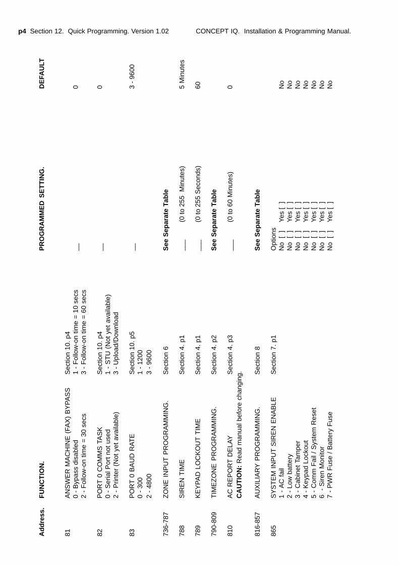
p4 Section 12. Quick Programming. Version 1.02 CONCEPT IQ. Installation & Programming Manual.
Ad
dre
ss.
FU
NC
TIO
N.
PR
OG
RA
MM
ED
SE
TT
ING
.D
EFA
ULT
81A
NS
WE
R M
AC
HIN
E (
FAX
) B
YP
AS
SS
ectio
n 10
. p4
0 -
Byp
ass
disa
bled
1 -
Fol
low
-on
time
= 1
0 se
cs__
02
- F
ollo
w-o
n tim
e =
30
secs
3 -
Fol
low
-on
time
= 6
0 se
cs
82P
OR
T 0
CO
MM
S T
AS
KS
ectio
n 10
. p4
__0
0 -
Ser
ial P
ort n
ot u
sed
1 -
ST
U (
Not
yet
ava
ilabl
e)2
- P
rinte
r (N
ot y
et a
vaila
ble)
3 -
Upl
oad/
Dow
nloa
d
83P
OR
T 0
BA
UD
RA
TE
Sec
tion
10. p
5__
3 -
9600
0 -
300
1 -
1200
2 -
4800
3 -
9600
736-
787
ZO
NE
IN
PU
T P
RO
GR
AM
MIN
G.
Sec
tion
6S
ee S
epar
ate
Tab
le
788
SIR
EN
TIM
ES
ectio
n 4.
p1
___
(0 to
255
Min
utes
)5
Min
utes
789
KE
YP
AD
LO
CK
OU
T T
IME
Sec
tion
4. p
1__
_(0
to 2
55 S
econ
ds)
60
790-
809
TIM
EZ
ON
E P
RO
GR
AM
MIN
G.
Sec
tion
4. p
2S
ee S
epar
ate
Tab
le
810
AC
RE
PO
RT
DE
LAY
Sec
tion
4. p
3__
_(0
to 6
0 M
inut
es)
0C
AU
TIO
N:
Rea
d m
anua
l bef
ore
chan
ging
.
816-
857
AU
XIL
IAR
Y P
RO
GR
AM
MIN
G.
Sec
tion
8S
ee S
epar
ate
Tab
le
865
SY
ST
EM
IN
PU
T S
IRE
N E
NA
BLE
Sec
tion
7. p
1O
ptio
ns1
- A
C f
ail
No
[ ]
Yes
[ ]
No
2 -
Low
bat
tery
No
[ ]
Yes
[ ]
No
3 -
Cab
inet
Tam
per
No
[ ]
Yes
[ ]
No
4 -
Key
pad
Lock
out
No
[ ]
Yes
[ ]
No
5 -
Com
m F
ail /
Sys
tem
Res
etN
o [
]Ye
s [
]N
o6
- S
iren
Mon
itor
No
[ ]
Yes
[ ]
No
7 -
PW
R F
use
/ Bat
tery
Fus
eN
o [
]Ye
s [
]N
o
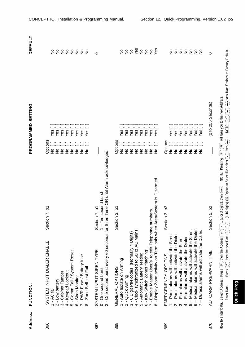
Section 12. Quick Programming. Version 1.02 p5CONCEPT IQ. Installation & Programming Manual.
How
to E
nter
Dat
a.Se
lect
Add
ress
:Pr
ess
, the
n th
e Ad
dres
s
.. (2
or 3
dig
its),
then
.
N
OTE
: Pr
essi
ng
w
ill ta
ke y
ou to
the
next
Add
ress
.
Ente
r Dat
a:Pr
ess
, the
n th
e ne
w D
ata
..
(1-1
6 di
gits
) OR
Opt
ion
to S
elec
t/De-
sele
ct
, the
n .
N
OTE
: ,
, s
ets
Dat
a/O
ptio
ns to
Fac
tory
Def
ault.
Qu
ick
Pro
g
Ad
dre
ss.
FU
NC
TIO
N.
PR
OG
RA
MM
ED
SE
TT
ING
.D
EFA
ULT
866
SY
ST
EM
IN
PU
T D
IALE
R E
NA
BLE
Sec
tion
7. p
1O
ptio
ns1
- A
C f
ail
No
[ ]
Yes
[ ]
No
2 -
Low
bat
tery
No
[ ]
Yes
[ ]
No
3 -
Cab
inet
Tam
per
No
[ ]
Yes
[ ]
No
4 -
Key
pad
Lock
out
No
[ ]
Yes
[ ]
No
5 -
Com
m F
ail /
Sys
tem
Res
etN
o [
]Ye
s [
]N
o6
- S
iren
Mon
itor
No
[ ]
Yes
[ ]
No
7 -
PW
R F
use
/ B
atte
ry f
use
No
[ ]
Yes
[ ]
No
8 -
Zon
e S
elf-
test
Fai
lN
o [
]Ye
s [
]N
o
867
SY
ST
EM
IN
PU
T S
IRE
N T
YP
ES
ectio
n 7.
p1
___
00
- O
ne s
econ
d bu
rst
1 –
Ten
seco
nd b
urst
2 -
One
sec
ond
burs
t eve
ry 6
0 se
cond
s fo
r S
iren
Tim
e O
R u
ntil
Ala
rm a
ckno
wle
dged
.
868
GE
NE
RA
L O
PT
ION
SS
ectio
n 3.
p1
Opt
ions
1 -
Aut
o Is
olat
e on
Arm
ing
No
[ ]
Yes
[ ]
No
2 -
Qui
ck A
rmin
gN
o [
]Ye
s [
]N
o3
- 6
Dig
it P
IN c
odes
(N
orm
ally
4 D
igits
)N
o [
]Ye
s [
]N
o4
- C
lock
syn
chro
nize
d to
50H
z A
C M
ains
.N
o [
]Ye
s [
]Ye
s5
- A
utom
atic
Bat
tery
Tes
ting
No
[ ]
Yes
[ ]
No
6 -
Key
Sw
itch
Zon
es “
latc
hing
”.N
o [
]Ye
s [
]N
o7
- E
nabl
e M
aste
r U
ser/
s to
edi
t Tel
epho
ne n
umbe
rs.
No
[ ]
Yes
[ ]
No
8 -
Dis
play
Zon
e ac
tivity
on
Term
inal
s w
hen
Are
a/S
yste
m is
Dis
arm
ed.
No
[ ]
Yes
[ ]
Yes
869
EM
ER
GE
NE
NC
Y O
PT
ION
SS
ectio
n 3.
p2
Opt
ions
1 –
Pan
ic a
larm
s w
ill a
ctiv
ate
the
Sire
n.N
o [
]Ye
s [
]N
o2
– P
anic
ala
rms
will
act
ivat
e th
e D
iale
r.N
o [
]Ye
s [
]N
o3
– F
ire a
larm
s w
ill a
ctiv
ate
the
Sire
n.N
o [
]Ye
s [
]N
o4
– F
ire a
larm
s w
ill a
ctiv
ate
the
Dia
ler.
No
[ ]
Yes
[ ]
No
5 –
Med
ical
ala
rms
will
act
ivat
e th
e S
iren.
No
[ ]
Yes
[ ]
No
6 –
Med
ical
ala
rms
will
act
ivat
e th
e D
iale
r.N
o [
]Ye
s [
]N
o7
– D
ures
s al
arm
s w
ill a
ctiv
ate
the
Dia
ler.
No
[ ]
Yes
[ ]
No
870
AU
TO
AR
M P
RE
-WA
RN
TIM
ES
ectio
n 5.
p2
___
(0 to
255
Sec
onds
)0
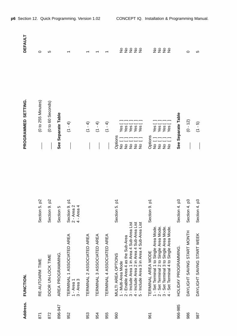
p6 Section 12. Quick Programming. Version 1.02 CONCEPT IQ. Installation & Programming Manual.
Ad
dre
ss.
FU
NC
TIO
N.
PR
OG
RA
MM
ED
SE
TT
ING
.D
EFA
ULT
871
RE
-AU
TO
AR
M T
IME
Sec
tion
5. p
2__
_(0
to 2
55 M
inut
es)
0
872
DO
OR
UN
-LO
CK
TIM
ES
ectio
n 9.
p2
___
(0 to
60
Sec
onds
)5
896-
947
AR
EA
PR
OG
RA
MM
ING
.S
ectio
n 5
See
Sep
arat
e Ta
ble
952
TE
RM
INA
L 1
AS
SO
CIA
TE
D A
RE
AS
ectio
n 9.
p1
___
(1 -
4)
11
- A
rea
12
- A
rea
23
- A
rea
34
- A
rea
4
953
TE
RM
INA
L 2
AS
SO
CIA
TE
D A
RE
A__
_(1
- 4
)1
954
TE
RM
INA
L 3
AS
SO
CIA
TE
D A
RE
A__
_(1
- 4
)1
955
TE
RM
INA
L 4
AS
SO
CIA
TE
D A
RE
A__
_(1
- 4
)1
960
MU
LTI
AR
EA
OP
TIO
NS
Sec
tion
5. p
1O
ptio
ns1
- M
ulti-
Are
a M
ode
No
[ ]
Yes
[ ]
No
2 -
Ena
ble
Are
a 4
as th
e S
ub-A
rea
No
[ ]
Yes
[ ]
No
3 -
Incl
ude
Are
a 1
in A
rea
4 S
ub-A
rea
List
No
[ ]
Yes
[ ]
No
4 -
Incl
ude
Are
a 2
in A
rea
4 S
ub-A
rea
List
No
[ ]
Yes
[ ]
No
5 -
Incl
ude
Are
a 3
in A
rea
4 S
ub-A
rea
List
No
[ ]
Yes
[ ]
No
961
TE
RM
INA
L A
RE
A M
OD
ES
ectio
n 9.
p1
Opt
ions
1 -
Set
Ter
min
al 1
to
Sin
gle
Are
a M
ode.
No
[ ]
Yes
[ ]
No
2 -
Set
Ter
min
al 2
to
Sin
gle
Are
a M
ode.
No
[ ]
Yes
[ ]
No
3 -
Set
Ter
min
al 3
to
Sin
gle
Are
a M
ode.
No
[ ]
Yes
[ ]
No
4 -
Set
Ter
min
al 4
to
Sin
gle
Are
a M
ode.
No
[ ]
Yes
[ ]
No
966-
985
HO
LID
AY
PR
OG
RA
MM
ING
.S
ectio
n 4.
p3
See
Sep
arat
e Ta
ble
986
DA
YLI
GH
T S
AV
ING
STA
RT
MO
NT
HS
ectio
n 4.
p3
___
(0 -
12)
0
987
DA
YLI
GH
T S
AV
ING
STA
RT
WE
EK
Sec
tion
4. p
3__
_(1
- 5
)5
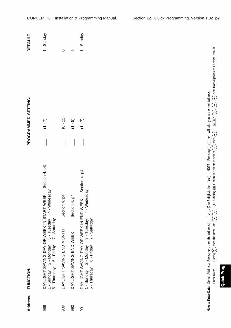
Section 12. Quick Programming. Version 1.02 p7CONCEPT IQ. Installation & Programming Manual.
How
to E
nter
Dat
a.Se
lect
Add
ress
:Pr
ess
, the
n th
e Ad
dres
s
.. (2
or 3
dig
its),
then
.
N
OTE
: Pr
essi
ng
w
ill ta
ke y
ou to
the
next
Add
ress
.
Ente
r Dat
a:Pr
ess
, the
n th
e ne
w D
ata
..
(1-1
6 di
gits
) OR
Opt
ion
to S
elec
t/De-
sele
ct
, the
n .
N
OTE
: ,
, s
ets
Dat
a/O
ptio
ns to
Fac
tory
Def
ault.
Qu
ick
Pro
g
988
DA
YLI
GH
T S
AV
ING
DA
Y-O
F-W
EE
K I
N S
TAR
T W
EE
K
S
ectio
n 4.
p3
___
(1 -
7)
1. S
unda
y1
- S
unda
y
2 -
Mon
day
3
- T
uesd
ay
4 -
Wed
esda
y5
- T
hurs
day
6
- F
riday
7
- S
atur
day
989
DA
YLI
GH
T S
AV
ING
EN
D M
ON
TH
Sec
tion
4. p
4__
_(0
- 1
2)0
990
DA
YLI
GH
T S
AV
ING
EN
D W
EE
KS
ectio
n 4.
p4
___
(1 -
5)
5
991
DA
YLI
GH
T S
AV
ING
DAY
-OF
-WE
EK
IN
EN
D W
EE
K
S
ectio
n 4.
p4
___
(1 -
7)
1. S
unda
y1
- S
unda
y
2 -
Mon
day
3
- T
uesd
ay
4 -
Wed
esda
y5
- T
hurs
day
6
- F
riday
7
- S
atur
day
Ad
dre
ss.
FU
NC
TIO
N.
PR
OG
RA
MM
ED
SE
TT
ING
.D
EFA
ULT
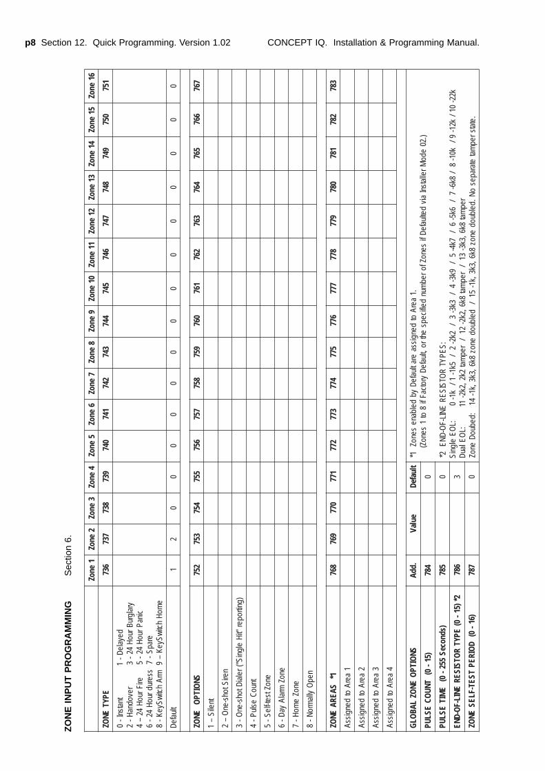
p8 Section 12. Quick Programming. Version 1.02 CONCEPT IQ. Installation & Programming Manual.
1enoZ
2enoZ
3enoZ
4enoZ
5enoZ
6enoZ
7enoZ
8enoZ
9enoZ
01enoZ
11enoZ
21enoZ
31enoZ
41enoZ
51enoZ
61enoZ
EPYTEN
OZ637
737837
937047
147247
347447
547647
747847
947057
157
deyaleD-1
tnatsnI-0
yralgruBruoH42-
3revodnaH-
2cinaPruoH
42-5
eriFruoH42
–4
erapS-7
sserudruoH42-
6e
moHhctiwSyeK
–9
mrAhctiwSyeK-
8
tluafeD1
20
00
00
00
00
00
00
0
SNOITP
OEN
OZ257
357457
557657
757857
957067
167267
367467
567667
767
tneliS–
1
neriStohs-enO
–2
)gnitroper"tiH
elgniS"(relaiDtohs-enO-
3
tnuoCesluP-
4
enoZtset-fleS-5
enoZmralA
yaD-6
enoZe
moH-7
nepO
yllamroN-
8
1*SAERA
ENOZ
867967
077177
277377
477577
677777
877977
087187
287387
1aerA
otdengissA
2aerA
otdengissA
3aerA
otdengissA
4aerA
otdengissA
SNOITP
OEN
OZLAB
OLG
.ddAeulaV
tluafeD.1
aerAot
dengissaeratluafeD
ybdelbane
senoZ1*
).20edo
MrellatsnIaiv
detluafeDfisenoZforeb
mundeificeps
ehtro,tluafeDyrotcaFfi
8ot
1senoZ(
:SEPYTR
OTSISERENIL-F
O-DNE2*
k22-01/
k21-9/
k01-8
/8k6-
7/
6k5-6
/7k4-
5/
9k3-4
/3k3-
3/
2k2-2
/5k1-
1/k1-
0:L
OEelgniS
repmat
8k6,3k3-31
/rep
mat8k6,2k2-
21/
repmat
2k2,2k2-11
:LOElauD
.etatsrepmat
etarapesoN.delbuod
enoz8k6,3k3,k1-
51/
delbuodenoz
8k6,3k3,k1-41
:debuoDenoZ
)51-0(
TNUOC
ESLUP487
0
)sdnoceS552-
0(E
MITESLUP
5870
2*)51-0(
EPYTR
OTSISERENIL-F
O-DNE687
3
)61-0(
DOIREP
TSET-FLESEN
OZ787
0
ZO
NE
IN
PU
T P
RO
GR
AM
MIN
GS
ectio
n 6.
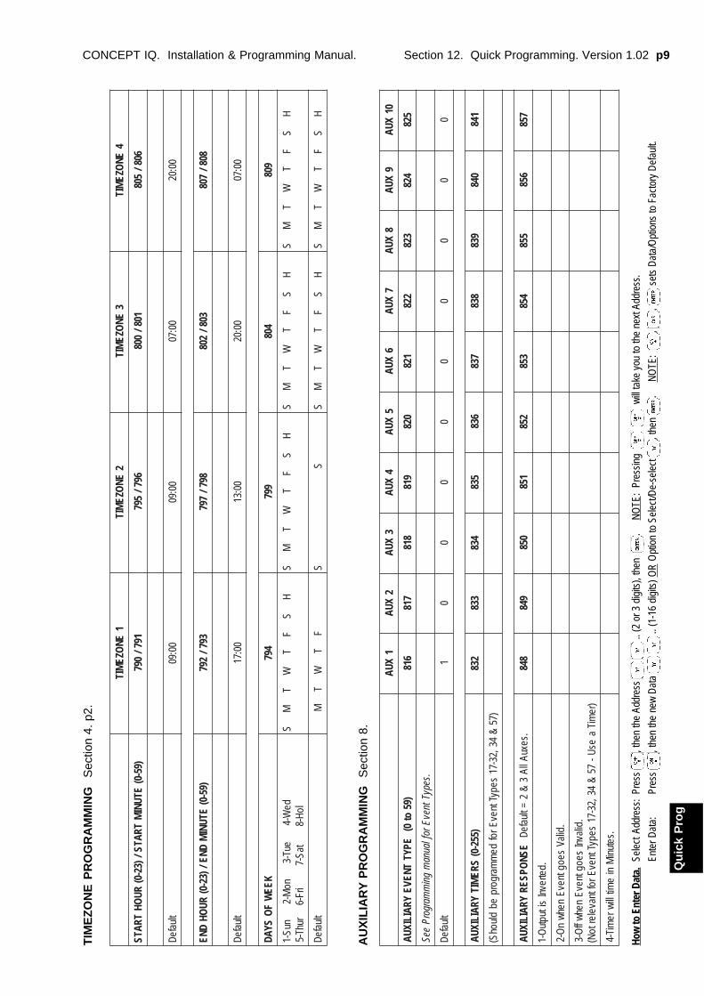
Section 12. Quick Programming. Version 1.02 p9CONCEPT IQ. Installation & Programming Manual.
How
to E
nter
Dat
a.Se
lect
Add
ress
:Pr
ess
, the
n th
e Ad
dres
s
.. (2
or 3
dig
its),
then
.
N
OTE
: Pr
essi
ng
w
ill ta
ke y
ou to
the
next
Add
ress
.
Ente
r Dat
a:Pr
ess
, the
n th
e ne
w D
ata
..
(1-1
6 di
gits
) OR
Opt
ion
to S
elec
t/De-
sele
ct
, the
n .
N
OTE
: ,
, s
ets
Dat
a/O
ptio
ns to
Fac
tory
Def
ault.
Qu
ick
Pro
g
1EN
OZEMIT
2EN
OZEMIT
3EN
OZEMIT
4EN
OZEMIT
)95-0(ETUNI
MTRATS/)32-0(
RUOH
TRATS197/
097697/
597108/
008608/
508
tluafeD00:90
00:9000:70
00:02
)95-0(ETUNI
MDNE/)32-0(
RUOH
DNE397/
297897/
797308/
208808/
708
tluafeD00:71
00:3100:02
00:70
KEEW
FO
SYAD497
997408
908
deW-4
euT-3no
M-2nuS-1
loH-8taS-7
irF-6ruhT-5
HS
FT
WT
MS
HS
FT
WT
MS
HS
FT
WT
MS
HS
FT
WT
MS
tluafeDF
TW
TM
SS
HS
FT
WT
MS
HS
FT
WT
MS
TIM
EZ
ON
E P
RO
GR
AM
MIN
GS
ectio
n 4.
p2.
AU
XIL
IAR
Y P
RO
GR
AM
MIN
GS
ectio
n 8.
1XUA
2XUA
3XUA
4XUA
5XUA
6XUA
7XUA
8XUA
9XUA
01XUA
)95ot
0(EPYT
TNEVEYRAILIXUA
618718
818918
028128
228328
428528
.sepyTtnevEroflaunam
gnim
margorPeeS
tluafeD1
00
00
00
00
0
)552-0(SRE
MITYRAILIXUA
238338
438538
638738
838938
048148
)75&
43,23-71sepyTtnevErof
dem
margorpeb
dluohS(
ESNOPSER
YRAILIXUA.sexuAllA
3&
2=tluafeD
848948
058158
258358
458558
658758
.detrevnIsituptu
O-1
.dilaVseogtnevE
nehwn
O-2
.dilavnIseogtnevE
nehwffO-3
)remiT
aesU-
75&
43,23-71sepyTtnevEroftnavelertoN(
.setuniM
nie
mitlliwremiT-4
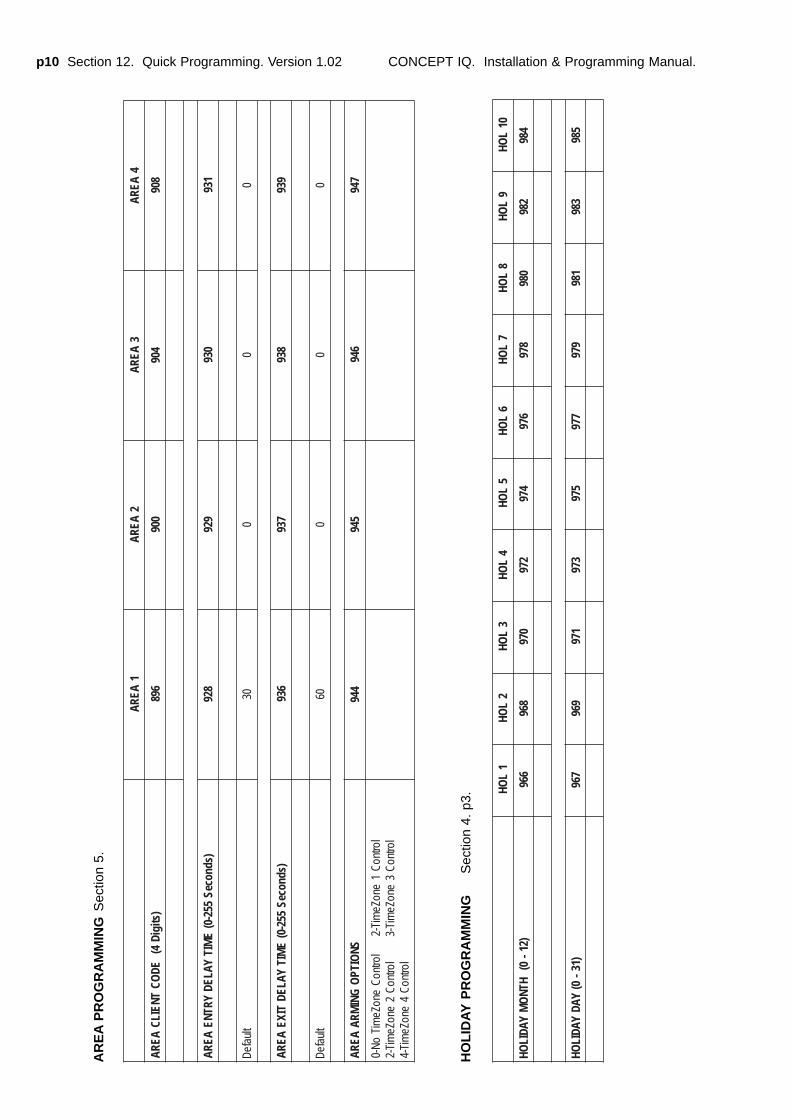
p10 Section 12. Quick Programming. Version 1.02 CONCEPT IQ. Installation & Programming Manual.
1AERA
2AERA
3AERA
4AERA
)stigiD4(
EDOC
TNEILCAERA
698009
409809
)sdnoceS552-0(
EMIT
YALEDYRTNE
AERA829
929039
139
tluafeD03
00
0
)sdnoceS552-0(
EMIT
YALEDTIXE
AERA639
739839
939
tluafeD06
00
0
SNOITP
OGNI
MRAAERA
449549
649749
lortnoC1
enoZemiT-2
lortnoCenoZe
miToN-0
lortnoC3
enoZemiT-3
lortnoC2
enoZemiT-2
lortnoC4
enoZemiT-4
1L
OH2
LOH
3L
OH4
LOH
5L
OH6
LOH
7L
OH8
LOH
9L
OH01
LOH
)21-0(
HTNO
MYADIL
OH669
869079
279479
679879
089289
489
)13-0(
YADYADIL
OH769
969179
379579
779979
189389
589
AR
EA
PR
OG
RA
MM
ING
Sec
tion
5.
HO
LID
AY
PR
OG
RA
MM
ING
Sec
tion
4. p
3.

Section 12. Quick Programming. Version 1.02 p11CONCEPT IQ. Installation & Programming Manual.
How
to E
nter
Dat
a.Se
lect
Add
ress
:Pr
ess
, the
n th
e Ad
dres
s
.. (2
or 3
dig
its),
then
.
N
OTE
: Pr
essi
ng
w
ill ta
ke y
ou to
the
next
Add
ress
.
Ente
r Dat
a:Pr
ess
, the
n th
e ne
w D
ata
..
(1-1
6 di
gits
) OR
Opt
ion
to S
elec
t/De-
sele
ct
, the
n .
N
OTE
: ,
, s
ets
Dat
a/O
ptio
ns to
Fac
tory
Def
ault.
Qu
ick
Pro
g
INS
TAL
LE
R M
OD
ES
SU
MM
AR
Y
MO
DE
01.
P
RO
GR
AM
MIN
G M
OD
E.
NE
XT
01
Ent
er P
IN;
...
, t
hen
,
the
n th
e M
ode
num
ber;
,
.T
he <
HO
ME
>,
<FA
ULT
> a
nd <
PW
R>
Lam
ps o
n th
e LE
D T
erm
inal
will
fla
sh s
imul
tane
ousl
y.
MO
DE
02.
D
EFA
ULT
ING
TH
E C
ON
TR
OL
MO
DU
LE
.N
EX
T 0
2
Ent
er P
IN;
...
, t
hen
,
the
n th
e M
ode
num
ber;
,
.T
he <
HO
ME
>,
<FA
ULT
> a
nd <
PW
R>
Lam
ps o
n th
e LE
D T
erm
inal
will
fla
sh s
imul
tane
ousl
y.
Sel
ect
the
Def
ault
Opt
ion:
P
ress
,
th
en t
he D
efau
lt O
ptio
n
(1 o
r 2
digi
ts),
th
en
Opt
ion
0:T
he C
ontr
ol M
odul
e m
emor
y is
com
plet
ely
clea
red
with
the
exc
eptio
n of
the
Ins
talle
r an
d M
aste
r U
ser
Cod
es.
Opt
ions
1 t
o 16
:T
he C
ontr
ol M
odul
e m
emor
y is
def
aulte
d to
the
Fac
tory
set
tings
AN
D t
he n
umbe
r of
Zon
es s
peci
fied
by t
he O
ptio
n se
lect
ed,
are
prog
ram
med
into
Are
a 1.
Opt
ion
49:
The
Mas
ter
Cod
e is
def
aulte
d to
the
Fac
tory
set
ting
and
all o
ther
pro
gram
min
g is
left
inta
ct.
CA
UT
ION
:D
efau
lting
the
Con
trol
Mod
ule
will
era
se a
ll cu
rren
t pr
ogra
mm
ing
stor
ed in
the
mem
ory
befo
re im
plem
entin
g an
y F
acto
ry d
efau
lt se
tting
s.
(Exc
ept
for
Opt
ion
49)
Res
et t
he C
ontr
ol M
odul
e:
Dis
conn
ect
the
AC
Inp
ut a
nd t
he B
atte
ry f
rom
the
Con
trol
Mod
ule,
the
n re
-con
nect
.
MO
DE
03
/ M
OD
E 0
4.
IMP
OR
T/E
XP
OR
T D
ATA
FR
OM
/TO
TH
E P
RO
GR
AM
MIN
G K
EY.
NE
XT
03/
NE
XT
04
Con
nect
the
Pro
gram
min
g K
ey t
o S
eria
l Por
t 0
on t
he C
ontr
ol M
odul
e.
Impo
rt D
ata
from
the
Pro
gram
min
g K
ey t
o th
e C
ontr
ol M
odul
e:E
nter
PIN
;
...
,
the
n
, t
hen
the
Mod
e nu
mbe
r;
,
.
Exp
ort
Dat
a fr
om t
he C
ontr
ol M
odul
e to
the
Pro
gram
min
g K
ey:
Ent
er P
IN;
...
, t
hen
,
the
n th
e M
ode
num
ber;
,
.
The
Lam
p on
the
Key
will
fla
sh t
o in
dica
te d
ata
is b
eing
cop
ied.
T
he T
erm
inal
bee
per
will
sou
nd 3
sho
rt b
eeps
if t
he o
pera
tion
was
suc
cess
ful,
or 1
long
bee
p if
unsu
cces
sful
.
MO
DE
05.
T
ER
MIN
AL
AR
EA
PR
OG
RA
MM
ING
.N
EX
T 0
5
Sel
ect
the
Term
inal
Pro
gram
min
g M
ode:
E
nter
PIN
;
...
,
the
n
, t
hen
the
Mod
e nu
mbe
r;
,
Sel
ect
the
Term
inal
Are
a M
ode:
(N
ot r
elev
ant
to E
nhan
ced
Term
inal
s w
hich
can
not
be s
et t
o M
ulti-
Are
a)P
ress
t
o S
et t
he c
urre
nt T
erm
inal
to
Sin
gle
Are
a M
ode.
Pre
ss
to
Set
the
cur
rent
Ter
min
al t
o M
ulti
Are
a M
ode.
Whe
n S
ingl
e A
rea
Mod
e is
sel
ecte
d, t
he d
efau
lt “A
ssoc
iate
d A
rea”
is A
rea
1 (G
ener
al A
rea)
Sel
ect
the
Ass
ocia
ted
Are
a:
(Sin
gle
Are
a M
ode
mus
t be
sel
ecte
d in
the
pre
viou
s st
ep)
Pre
ss t
he n
umbe
r (
1 to
4)
of t
he A
rea.
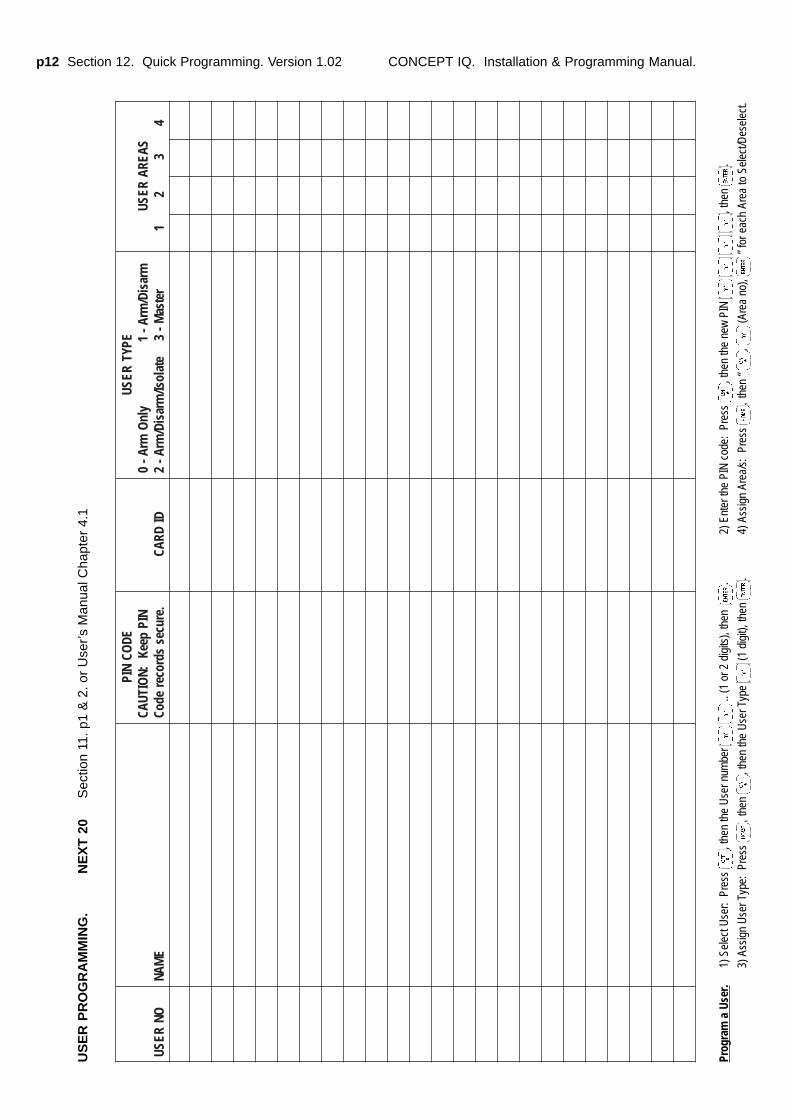
p12 Section 12. Quick Programming. Version 1.02 CONCEPT IQ. Installation & Programming Manual.
ONRESU
EMAN
EDOC
NIPNIP
peeK:N
OITUAC.eruces
sdroceredoC
DIDRAC
EPYTRESU
mrasiD/mrA-
1yln
OmrA-
0retsa
M-3
etalosI/mrasiD/
mrA-2
SAERARESU
43
21
US
ER
PR
OG
RA
MM
ING
.N
EX
T 2
0S
ectio
n 11
. p1
& 2
. or
Use
r’s M
anua
l Cha
pter
4.1
Prog
ram
a U
ser.
1) S
elec
t Use
r: P
ress
, t
hen
the
Use
r num
ber
..
(1 o
r 2 d
igits
), th
en
.2)
Ent
er th
e PI
N c
ode:
Pre
ss
, the
n th
e ne
w P
IN
, t
hen
.
3) A
ssig
n U
ser T
ype:
Pre
ss
, the
n , t
hen
the
Use
r Typ
e (1
dig
it), t
hen
.4)
Ass
ign
Area
/s:
Pres
s ,
then
“ ,
(Are
a no
), ”
for e
ach
Area
to S
elec
t/Des
elec
t.
Section 13. Index. Version 1.02 p1CONCEPT IQ. Installation & Programming Manual.
Ind
ex
Section 13. Index
Section 0. Title and Document Version log.
Section 1. INSTALLATION MANUAL.1. Installer and Master User Operations (NEXT functions) ............................................................22. Control Module ...............................................................................................................................33. LED Terminal .................................................................................................................................74. Programming Key ..........................................................................................................................85. Enhanced LED Terminal ...............................................................................................................96. Expansion Card .............................................................................................................................117. DTMF Card .....................................................................................................................................13
Section 2. INTRODUCTION TO PROGRAMMING AND SYSTEM OVERVIEW.1. 1.1 System Overview ....................................................................................................................2
1.2 Types of Users .......................................................................................................................31.3 Default Users ..........................................................................................................................3
2. The LED Terminal2.1 Key Functions .........................................................................................................................42.2 Beeper Indications ..................................................................................................................42.3 Lamp Indications ....................................................................................................................5
3 Installer Modes3.1 Overview .................................................................................................................................63.2 Accessing the Installer Modes ...............................................................................................63.3 Mode 01. Programming Mode ..............................................................................................73.4 Mode 02. Defaulting Mode ....................................................................................................73.5 Factory Default Database settings .......................................................................................83.6 Mode 03. Import Data from Programming Key ....................................................................93.7 Mode 04. Export Data to Programming Key ........................................................................93.8 Mode 05. Terminal Area Programming ................................................................................9
4 Programming Techniques4.1 The System Database ............................................................................................................104.2 Selecting and Programming the Data ...................................................................................104.3 Example of Programming ......................................................................................................11
5 Types of Data5.1 Overview .................................................................................................................................125.2 “Value” Data ............................................................................................................................125.3 “Options” Data ........................................................................................................................13
6 Recommended Programming Sequence .....................................................................................14
PROGRAMMING REFERENCE:
Section 3. General Options.General Options.........................................................................................................................................1Emergenency Options ...............................................................................................................................2
Section 4. Times.Siren Time ............................................................................................................................................1Keypad Lockout Time................................................................................................................................1TimeZones ............................................................................................................................................2AC Report Delay ........................................................................................................................................3Holidays ............................................................................................................................................3Daylight Saving ..........................................................................................................................................3Real-Time Clock ........................................................................................................................................4
Section 5. Areas.Area Modes ............................................................................................................................................1Multi Area Systems ....................................................................................................................................1Multi Area Options .....................................................................................................................................1Area Entry Delay........................................................................................................................................1Area Exit Delay ..........................................................................................................................................1Area Arming Options .................................................................................................................................2Area AutoArm Pre-warn time ....................................................................................................................2Area Re-AutoArm time ..............................................................................................................................2
p2 Section 13. Index. Version 1.02 CONCEPT IQ. Installation & Programming Manual.
Section 6. Zone Inputs.Per Zone Options...................................................................................................................................... 1
Zone Type (16 Addresses) ........................................................................................................... 1Zone Options (16 Addresses) ...................................................................................................... 2Zone Areas (16 Addresses) ......................................................................................................... 3
Global Zone OptionsMax Pulse ...................................................................................................................................... 3Pulse Time .................................................................................................................................... 3End-of-Line Resistor Type ........................................................................................................... 4Self Test Period ............................................................................................................................ 4
Section 7. System Inputs.System Input Siren Enable ...................................................................................................................... 1System Input Dialer Enable ..................................................................................................................... 1System Input Siren Type .......................................................................................................................... 1System Input Mapping and Functional description ................................................................................ 2
Section 8. Auxiliary Outputs.Auxiliary Event Type ................................................................................................................................. 1Auxiliary Timers ........................................................................................................................................ 2Auxiliary Response ................................................................................................................................... 2Auxiliary Event Type details ..................................................................................................................... 3, 4
Section 9. Terminals.Terminal Area Mode ................................................................................................................................. 1Terminal Associated Area (4 Addresses) ............................................................................................... 1Door Unlock Time ..................................................................................................................................... 2Commissioning Terminals ........................................................................................................................ 2
Section 10. Communications.Dialer
Telephone numbers ...................................................................................................................... 1Primary telephone number (15 Addresses) .............................................................................. 2Secondary telephone number (15 Addresses) .......................................................................... 2Call back telephone number (15 Addresses) ........................................................................... 2Reporting format ........................................................................................................................... 2Dialer options ................................................................................................................................ 2Maximum Dial attempts ................................................................................................................ 2
Test reportingTest report period ......................................................................................................................... 3Test report hour ............................................................................................................................ 3Test report minute ......................................................................................................................... 3
Remote connectRemote connect options............................................................................................................... 3Rings to answer ............................................................................................................................ 3Answer machine bypass .............................................................................................................. 3
Serial Port OptionsPort 0 Communications Task ....................................................................................................... 4Port 0 Baud rate ............................................................................................................................ 4
Client CodesGeneral Area / Area 1 Client Code (4 Addresses) .................................................................... 4Area 2 Client Code (4 Addresses) .............................................................................................. 4Area 3 Client Code (4 Addresses) .............................................................................................. 4Area 4 Client Code (4 Addresses) .............................................................................................. 4
Contact ID Event Codes ........................................................................................................................... 5
Section 11. Users.Installer PIN Code ......................................................................................................................... 1Adding / Changing Users ............................................................................................................. 1Deleting Users .............................................................................................................................. 2
Section 12. Quick Programming. (Includes Programming record sheets)Quick Programming ...................................................................................................................... 1Installer Programming record sheets .......................................................................................... 3Installer Modes summary.............................................................................................................. 11User Database record sheets ...................................................................................................... 12

![Programming Languages Version 1 - basu.ac.iralvand.basu.ac.ir/~dezfoulian/files/PL/[PL] Programming Languages...Programming Languages Version 1.02 ... you may accept compensation in](https://img.pdfslide.us/doc/110x75/5ae65fc57f8b9a8b2b8d2ef7/programming-languages-version-1-basuac-dezfoulianfilesplpl-programming.jpg)