Embed Size (px)
Citation preview
pentair.com BE
991 (
03-1
5-20
) 20
20Pe
ntai
r. A
ll R
ight
s R
eser
ved
INSTALLATION AND OPERATION MANUAL
VERTICAL MULTISTAGE PUMPSBVM SERIES
BERKELEY

2 BE991 (03-15-20)
TABLE OF CONTENTS
SECTION .................................................................................................................................................................................................. PAGE
Safety Information ................................................................................................................................................................................... 3
General Information .................................................................................................................................................................................. 4
Installation ................................................................................................................................................................................................ 5
Operation & Maintenance ......................................................................................................................................................................... 8
Dimension Tables ....................................................................................................................................................................................14
Parts List ................................................................................................................................................................................................44
Troubleshooting ..................................................................................................................................................................................... 50
Warranty ..................................................................................................................................................................................................51
3 BE991 (03-15-20)
SAFETY SYMBOLS
This is the safety alert symbol. When you see this symbol on your pump or in this manual, look for one of the following signal words and be alert to the potential for personal injury:
warns about hazards that will cause serious personal injury, death or major property damage if ignored.
warns about hazards that can cause serious personal injury, death or major property damage if ignored.
warns about hazards that will or can cause minor personal injury or property damage if ignored.
The word NOTICE indicates special instructions that are important but not related to hazards.
GENERAL SAFETY� Carefully read and follow all safety instructions in this
manual and on the unit itself.
� Follow all applicable local and state codes and regulations.
� Keep safety labels/nameplates in good condition, replacing any missing or damaged labels.
� Install pump according to all code requirements.� Compare pump nameplate data with desired operating
range.� Pump only liquids compatible with pump component
materials (that is, liquids that will not attack the pump).� Make sure plumbing is adequate to handle system
pressure.� Periodically perform maintenance inspection on pump and
system components.� Wear safety glasses at all times when working on pumps.
CALIFORNIA PROPOSITION 65 WARNING
This product and related accessories contain chemicals known to the State of California to cause cancer, birth defects or other reproductive harm.
INSPECT THE SHIPMENTThe vertical multistage centrifugal inline pump has been carefully inspected and packaged to assure safe delivery. Inspect the pump and fittings and report to the carrier any items which are damaged or missing.
ELECTRICAL SAFETY
Hazardous voltage. Can shock, burn, or kill. When installing, operating, or servicing this pump, follow the safety instructions listed below.
� All electrical work should be performed by a qualified electrician in accordance with the National Electrical Code and all local codes and regulations.
� Make sure that the motor voltage, phase, and frequency match the incoming electrical supply. The proper operating voltage and other electrical information can be found on the motor nameplate. These motors are designed to run up to ±10% of the nameplate-rated voltage.
� The wiring connection diagram can be found on either a plate attached to the motor or on a diagram inside the terminal box cover.
SAFETY INFORMATION

4 BE991 (03-15-20)
OVERVIEW
Berkeley multistage in-line centrifugal pumps are designed for liquid transfer, circulation, and pressure boosting of hot or cold clean water or other thin, non-explosive liquids, not containing solid particles or fibers, which will not chemically attack the pump materials.
Typical Installations include: � Municipal water supply and pressure boosting
� Boiler feed and condensate systems
� Cooling water systems
� Irrigation
� Fire fighting
GENERAL INFORMATION
NAMEPLATE INFORMATION
PUMP MODEL #
BILL OF MATERIAL #
MOTOR MODEL #
MOTOR SERIAL #
H.P.
VOLTS/Hz/PH
RATED AMP DRAW
SPECIFICATIONS
Temperature:� Maximum Ambient Temperature: 104° F (40° C)
� Liquid Temperature Range: 5° F to 250° F (-15° C to +120° C)
Maximum Permissible Operating Pressure� Flow Series 1 through 20: 360 psi
� Flow Series 33 through 90: 435 psi
Maximum operating pressure = Inlet pressure + maximum pump differential head
Electrical Data: See Motor Nameplate
Dimesniosn & Port-to-Port Lengths: See Dimesnion Tables
Record the following information from the motor and pump nameplates for future reference;
5 BE991 (03-15-20)
LOCATION
� Locate pump in a dry, well ventilated area, not subject to freezing or extreme variations in temperature.
� Mount pump a minimum of 6” from any obstruction or hot surface.
� Install the pump with the motor shaft vertical.
� Make sure that an adequate supply of cool air reaches the motor cooling fan. Maximum ambient air temperature is 104° F (40° C).
� For open systems requiring suction lift, locate the pump as close to the water source as possible.
FOUNDATION
Foundation should be concrete or a similarly rigid foundation to provide a secure, stable mounting base for the pump.
Secure pump to foundation using all bolt holes. Refer to the Pump Dimensions section for bolt plate dimensions. Be sure that all four pads on the base are properly supported.
Shim pump base to make sure that pump is level.
PIPING
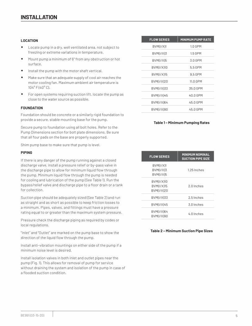
If there is any danger of the pump running against a closed discharge valve, install a pressure relief or by-pass valve in the discharge pipe to allow for minimum liquid flow through the pump. Minimum liquid flow through the pump is needed for cooling and lubrication of the pump (See Table 1). Run the bypass/relief valve and discharge pipe to a floor drain or a tank for collection.
Suction pipe should be adequately sized (See Table 2) and run as straight and as short as possible to keep friction losses to a minimum. Pipes, valves, and fittings must have a pressure rating equal to or greater than the maximum system pressure.
Pressure check the discharge piping as required by codes or local regulations.
“Inlet” and “Outlet” are marked on the pump base to show the direction of the liquid flow through the pump.
Install anti-vibration mountings on either side of the pump if a minimum noise level is desired.
Install isolation valves in both inlet and outlet pipes near the pump (Fig. 1). This allows for removal of pump for service without draining the system and isolation of the pump in case of a flooded suction condition.
INSTALLATION
FLOW SERIES MINIMUM PUMP RATE
BVM(I/X)1 1.0 GPM
BVM(I/X)3 1.5 GPM
BVM(I/X)5 3.0 GPM
BVM(I/X)10 5.5 GPM
BVM(I/X)15 9.5 GPM
BVM(I/X)20 11.0 GPM
BVM(I/X)33 35.0 GPM
BVM(I/X)45 40.0 GPM
BVM(I/X)64 45.0 GPM
BVM(I/X)90 45.0 GPM
Table 1 – Minimum Pumping Rates
FLOW SERIESMINIMUM NOMINALSUCTION PIPE SIZE
BVM(I/X)1BVM(I/X)3BVM(I/X)5
1.25 Inches
BVM(I/X)10BVM(I/X)15BVM(I/X)20
2.0 Inches
BVM(I/X)33 2.5 Inches
BVM(I/X)45 3.0 Inches
BVM(I/X)64BVM(I/X)90
4.0 Inches
Table 2 – Minimum Suction Pipe Sizes

6 BE991 (03-15-20)
If the system pressure is greater than the pump’s maximum inlet pressure, the limits of the pump can be exceeded if the discharge pressure backs up to the inlet side of the pump. Installation of a check valve in the discharge pipe is recommended to prevent this condition.
Make sure, especially on the inlet side of the pump, that there are no airlocks in the system. See Fig. 2 for correct pipe work to avoid airlocks. The suction pipe should be level or slightly rising.
Support all piping independently of the pump so the weight of the piping system does not strain the pump case. Make sure that the expansion and contraction of the piping system from temperature variations cannot put a strain on the pump.
If the system or pump must be drained periodically (especially if the discharge pipe is horizontal or slopes downward away from the pump), install a loop and vacuum valve as shown in Fig. 3 to protect the pump against running dry. The highest point of the loop should be at least as high as the lowest point of the motor. This loop/valve combination will allow the pump and the system to be drained independently of one another.
INSTALLATION
4218 0702
Inlet Outlet
NippleOri�ce
Bypass Line
12" Min. to prevent
erosion
Isolation Valves
Figure 1 – Bypass Requirement with Closed Discharge Valve
O.K.
3347 1198
O.K.
Figure 2 – Prevent Air Lock
3346 1198
Vacuum Valve
Figure 3 – Loop And Vacuum Valve Install
7 BE991 (03-15-20)
ELECTRICAL
Hazardous voltage. Can shock, burn, or kill.
All electrical work should be performed by a qualified electrician in accordance with the National Electrical Code and all local codes and regulations.
Make sure that the motor voltage, phase, and frequency match the incoming electrical supply. The proper operating voltage and other electrical information can be found on the motor nameplate.
These motors are designed to run up to ±10% of the nameplate-rated voltage. The wiring connection diagram can be found on either a plate attached to the motor or on a diagram inside the terminal box cover.
� If voltage variations are greater than ±10% do not operate the pump.
� Incorrect voltage can cause fire or serious damage to the motor and voids warranty.
� Ground the pump motor correctly before connecting it to the power supply.
� Follow the wiring instructions when connecting the motor to the power lines.
Position of Terminal Box
To turn the motor so that the terminal box faces the right direction, proceed as follows:1. Disconnect the power to the pump motor.2. Remove the coupling guards (use a screwdriver).3. Remove the couplings.4. Remove the bolts that fasten the motor to the pump.5. Turn the motor to the required position (in quarter-turn
increments).
6. Follow steps 10–18 under Motor Replacement.
INSTALLATION
Field Wiring
All wiring connections and wiring sizes must meet National Electrical Code and local requirements.
Motor ProtectionSee the motor nameplate for electrical connection/wiring diagram.
Berkeley pumps must be used with the proper size and type of motor starter to ensure protection against damage from low voltage, phase failure, current imbalances, and overloads. The overload should be sized to trip at the full-load current rating of the motor.

8 BE991 (03-15-20)
OPERATIONS & MAINTENANCE
OPERATIONS
PRIMING
Risk of explosion and scalding. Do not run the pump with the discharge valve closed; the water in the pump may boil, causing risk of explosion and steam burns to anyone nearby.
Risk of electric shock. Can shock, burn or kill.
Disconnect all power to the pump before servicing or working on the pump.
Make sure that the power is locked out and that the pump cannot be accidentally started.
Operation of closed systems or open systems with the liquid level above the pump priming plug:
1. Close the discharge isolating valve and loosen the needle valve located in the assembly in the pump head (Fig. 4). Do not remove the needle valve.
2. Slowly open the isolation valve in the suction pipe until a steady stream of liquid runs out the vent in the priming port.
3. Tighten needle valve to 25 inch-pounds. Completely open isolation valves.
4. Watch the direction of the priming plug and make sure that the liquid escaping from it does not injure persons nearby or damage the motor or other components. In hot water installations, pay particular attention to the risk of injury from scalding hot water.
5. Refer to the Starting section before proceeding further.
Operation of open systems with the liquid level below the top of the pump:
NOTICE: The suction pipe requires a check valve or isolation valve.
1. Close the discharge isolation valve.
2. Remove the vented priming plug.
3. Pour liquid through the priming port until the suction pipe and the pump are completely filled with liquid.
4. Replace the vented priming plug and tighten it securely.
5. Repeat Steps 1-4 until the pump is primed.
6. Refer to the Starting section before proceeding any further.
ROTATION DIRECTION
NOTICE: Do not disconnect the motor from the shaft to check the direction of rotation. If you remove the coupling, then you must adjust the shaft position when you reinstall it. This must be done before starting the pump.
Arrows on the pump head show the correct direction of rotation. When seen from the motor fan, the pump should rotate counterclockwise ( ).
For pump motors without a fan remove one of the coupling guards and look at the coupling to determine the direction of rotation. Turn off the pump and replace coupling guard.
Do not check the direction of rotation until the pump has been filled with liquid. See “Priming” directions.
1. Switch power off.
2. Remove the coupling guard and rotate the pump shaft to be certain it can turn freely. Replace the coupling guard.
3. Verify that the electrical connections are in accordance with the wiring diagram on the motor.
4. If the fan is visible, turn on and off to verify rotation.
5. To reverse the direction of rotation, first switch OFF the power supply.
6. On three-phase motors, switch 2 of the 3 power leads on the load side of the starter. On single-phase motors, see the connection diagram on the motor nameplate. Change the wiring as indicated.
Risk of electric shock. Can shock, burn or kill. Ground the pump motor correctly before connecting to power supply per article 250-80 of National Electrical Code (NEC) in the U.S., or the Canadian Electrical Code (CEC), as applicable.
7. Switch on the power supply and recheck the direction of motor rotation.
3348 1198
VentedPrimingPlug
DrainPlug
Back off needle valve to vent air. Retighten to 25 in.-lbs. when vent port runs a steady stream of water.
Figure 4 – Priming and Drain Plugs

9 BE991 (03-15-20)
OPERATIONS & MAINTENANCE
STARTING
1. If a suction line isolation valve has been installed, check to be sure that it is completely opened.
2. For initial starting, the isolation valve in the discharge pipe should be almost closed.
3. Start the pump.
4. When the piping system has been filled with liquid, slowly open the discharge isolation valve until it is completely open. Opening the valve too fast may result in water hammer in the discharge pipe.
If the pump or system start to rattle, the pump is cavitating; to avoid damage to the pump, reduce the flow through the discharge isolation valve until the rattling stops. If this does not give adequate flow for your installation, call your installer or system designer.
5. Record the voltage and amperage of the motor. Adjust the motor overloads if required.
6. If pressure gauges have been installed, check and record operating pressures.
7. Check all controls for proper operation.
MOTOR BEARING
For the greasing schedule and procedure of the motor bearings, follow the motor manufacturers recommendations.
MAINTENANCE
MOTOR REPLACEMENT
The reference numbers [shown as (11) or (88)] refer to the exploded views. See the appropriate exploded view for your model series.
Risk of electric shock. Can shock, burn or kill. Disconnect all power to the pump before servicing or working on pump. Make sure that power is locked out and that pump cannot be accidentally started.
1. Disconnect the power to the pump motor.
2. Close the nearest suction and discharge valves.
3. Remove the coupling guards (54).
4. Remove the socket head screws (73) and the coupling halves (44) from the shaft (37). See Fig. 6.
NOTICE: Socket head screws are metric. See Table 3 for specific metric driver sizes.
5. If your pump has a shaft pin (72), remove it.
6. Remove the motor bolts (74/92) and flatwashers that hold the motor and the motor stool (36/53) together.
7. Pull the old motor up and off of the motor bracket. Make a note of the orientation of the conduit box on the motor.
8. Thoroughly clean the surfaces of the mounting flanges on the new motor and the pump end.
9. Install the new motor on the pump with the conduit box in the desired position.
10. Lubricate the motor bolts (74/92) with oil.
11. Reinstall the flatwashers and motor bolts (74/92) that hold the motor and the motor stool (36/53) together, then tighten the bolts evenly and diagonally. See Table 3 for torque specifications.
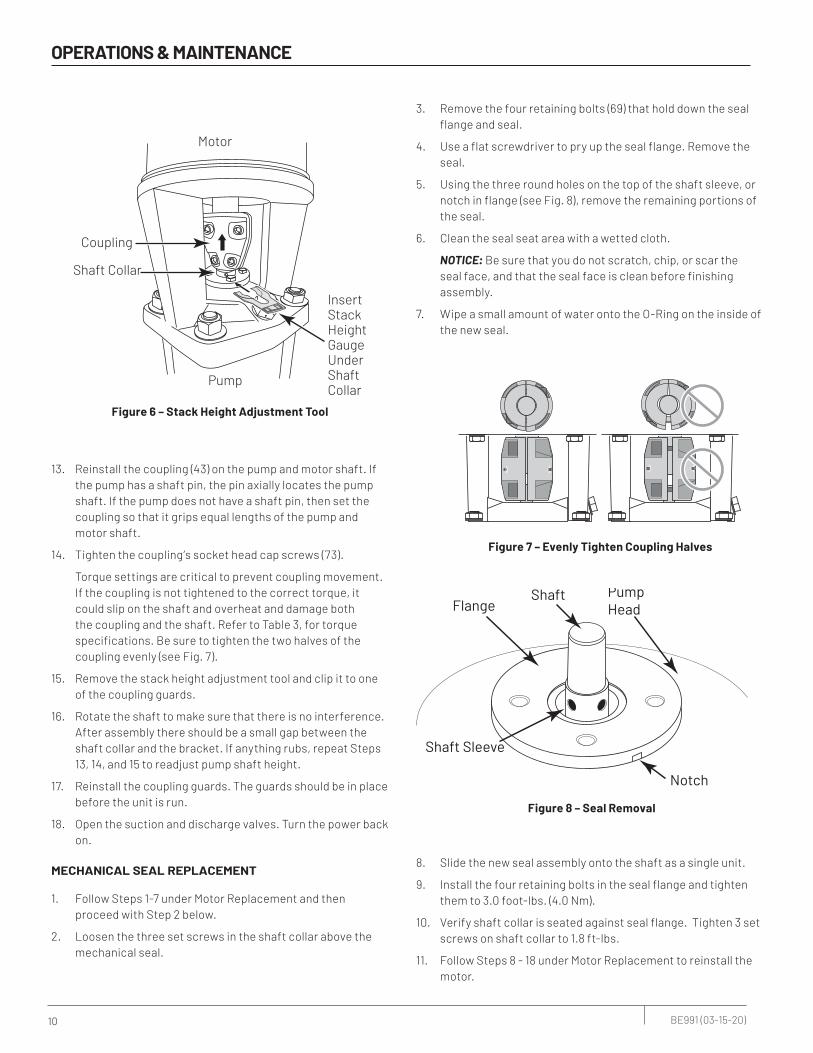
12. BVM(I/X)1–BVM(I/X)20: Reinstall the shaft pin (72) if your pump has one. Raise the height of the pump shaft by using the shaft pin (72) as a lift point (you may have to a put a block under the pin and lift with a flat screwdriver). Insert the stack height adjustment tool (see Fig. 6) in below the shaft collar and let the shaft collar rest on it.
BVM(I/X)33–BVM(X)90: Pick up the shaft (if necessary, temporarily reinstall the coupling to provide a grip to lift by) and insert the stack height adjustment tool (see Fig. 6) below the shaft collar. Let the shaft collar rest on it.
3358 1111 Figure 5 – Socket Head Screws and Couple Halves
10 BE991 (03-15-20)
OPERATIONS & MAINTENANCE
13. Reinstall the coupling (43) on the pump and motor shaft. If the pump has a shaft pin, the pin axially locates the pump shaft. If the pump does not have a shaft pin, then set the coupling so that it grips equal lengths of the pump and motor shaft.
14. Tighten the coupling’s socket head cap screws (73).
Torque settings are critical to prevent coupling movement. If the coupling is not tightened to the correct torque, it could slip on the shaft and overheat and damage both the coupling and the shaft. Refer to Table 3, for torque specifications. Be sure to tighten the two halves of the coupling evenly (see Fig. 7).
15. Remove the stack height adjustment tool and clip it to one of the coupling guards.
16. Rotate the shaft to make sure that there is no interference. After assembly there should be a small gap between the shaft collar and the bracket. If anything rubs, repeat Steps 13, 14, and 15 to readjust pump shaft height.
17. Reinstall the coupling guards. The guards should be in place before the unit is run.
18. Open the suction and discharge valves. Turn the power back on.
MECHANICAL SEAL REPLACEMENT
1. Follow Steps 1-7 under Motor Replacement and then proceed with Step 2 below.
2. Loosen the three set screws in the shaft collar above the mechanical seal.
3. Remove the four retaining bolts (69) that hold down the seal flange and seal.
4. Use a flat screwdriver to pry up the seal flange. Remove the seal.
5. Using the three round holes on the top of the shaft sleeve, or notch in flange (see Fig. 8), remove the remaining portions of the seal.
6. Clean the seal seat area with a wetted cloth.
NOTICE: Be sure that you do not scratch, chip, or scar the seal face, and that the seal face is clean before finishing assembly.
7. Wipe a small amount of water onto the O-Ring on the inside of the new seal.
Shaft Sleeve
Shaft
Notch
FlangePumpHead
8. Slide the new seal assembly onto the shaft as a single unit.
9. Install the four retaining bolts in the seal flange and tighten them to 3.0 foot-lbs. (4.0 Nm).
10. Verify shaft collar is seated against seal flange. Tighten 3 set screws on shaft collar to 1.8 ft-lbs.
11. Follow Steps 8 - 18 under Motor Replacement to reinstall the motor.
Pump
3359 0511
InsertStackHeightGaugeUnderShaftCollar
Coupling
Motor
Shaft Collar
Figure 6 – Stack Height Adjustment Tool
3361 1298
Figure 7 – Evenly Tighten Coupling Halves
Figure 8 – Seal Removal
11 BE991 (03-15-20)
REPLACING PUMP STACK
The reference numbers [shown as (11) or (88)] refer to the exploded views. See the appropriate exploded view for your model series.
1. Follow Steps 1-7 under Motor Replacement, then proceed with step 2 below.
2. Remove the motor bracket adapter plate (50), if your pump has one.
3. Follow Steps 2-5 under Mechanical Seal Replacement and then proceed with Step 3 below.
4. Remove the staybolt nuts (77) and flatwashers (78) from the staybolts (81). Use vicegrips, if necessary, to prevent the staybolts from unscrewing out of the pump base. Note: It is not necessary to remove the staybolts when replacing the stack.
5. With the base firmly attached to a solid floor, pull the motor stool (36) or motor stool/pump head assembly (36/53 or 36/56) straight up off the staybolts.
6. Make a note of the orientation of any tabs in the top of the stack assembly, then remove the stack assembly by pulling it straight up.
7. Install the new stack assembly, making sure that the orientation of the tabs matches the orientation of the tabs on the old stack assembly.
8. Replace the stack sleeve O-Ring (82) located in the motor stool (36/53) or pump head (36/56). Make sure that the new O-Ring is evenly seated in the O-Ring groove in the motor stool or pump head.
9. Apply water to the stack sleeve O-Ring in the motor stool/pump head (82) and to the top of the stack sleeve (48)
10. BVM1–BVM20: Slide the motor stool (36) over the staybolts (81) and onto the sleeve (48). Be sure the stack sleeve O-Ring seats in the pump head. Add the staybolt nuts and washers (77,78) and tighten them to torque specifications listed in Table 3.
BVM(I/X)1–20: Mount the pump head (56) on the stack sleeve (48). Be sure the stack sleeve O-Ring (82) seats in the groove in the pump head. Follow it with the motor stool (36) which goes over the staybolts (81) and seats on the pump head. Slide the pump head (36) over the staybolts onto the stack sleeve (48). Be sure the stack sleeve O-Ring seats in the pump head. Add the staybolt nuts and washers (77,78) and tighten them to torque specifications listed in Table 3.
BVM(I/X)33, BVM(X)45–BVM(X)90: Slide the pump head (36) over the staybolts onto the stack sleeve (48). Be sure the stack sleeve O-Ring seats in the pump head. Add the staybolt nuts and washers (77,78) and tighten them to torque specifications listed in Table 3. Place the motor stool (53) on the pump head and fasten it with four pump head bolts (74A). Tighten the pump head bolts to torque specifications given in Table 3.
11. Make sure that the stack can rotate freely.
12. Follow Steps 6–11 under Mechanical Seal Replacement.
13. Follow Steps 8–18 under Motor Replacement to reinstall the motor.
OPERATIONS & MAINTENANCE
12 BE991 (03-15-20)
OPERATIONS & MAINTENANCE
START/STOP FREQUENCY
Check pump cycling frequency and make sure that the pump starts per hour do not exceed the motor manufacturer’s specification.
FROST PROTECTION
1. If you do not use your pump during seasons of frost, drain it and add a glycol based antifreeze (50/50 mixture) to avoid damage.
Risk of flooding. Can cause personal injury and/or property damage. Watch the direction of the priming plug and make sure that liquid escaping from it does not injure persons nearby or damage the motor or other components. In hot water installations, pay particular attention to the risk of injury from scalding hot water.
2. Upon restart dispose of spent antifreeze properly.
3. Do not replace the drain plug or tighten the priming plug until you put the pump back in service again.
13 BE991 (03-15-20)
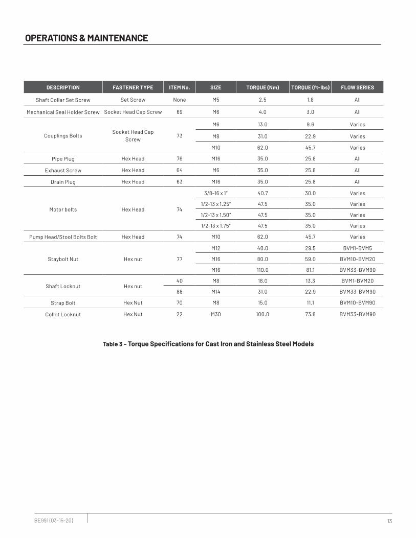
Table 3 – Torque Specifications for Cast Iron and Stainless Steel Models
DESCRIPTION FASTENER TYPE ITEM No. SIZE TORQUE (Nm) TORQUE (ft-lbs) FLOW SERIES
Shaft Collar Set Screw Set Screw None M5 2.5 1.8 All
Mechanical Seal Holder Screw Socket Head Cap Screw 69 M6 4.0 3.0 All
Couplings BoltsSocket Head Cap
Screw73
M6 13.0 9.6 Varies
M8 31.0 22.9 Varies
M10 62.0 45.7 Varies
Pipe Plug Hex Head 76 M16 35.0 25.8 All
Exhaust Screw Hex Head 64 M6 35.0 25.8 All
Drain Plug Hex Head 63 M16 35.0 25.8 All
Motor bolts Hex Head 74
3/8-16 x 1” 40.7 30.0 Varies
1/2-13 x 1.25” 47.5 35.0 Varies
1/2-13 x 1.50” 47.5 35.0 Varies
1/2-13 x 1.75” 47.5 35.0 Varies
Pump Head/Stool Bolts Bolt Hex Head 74 M10 62.0 45.7 Varies
Staybolt Nut Hex nut 77
M12 40.0 29.5 BVM1-BVM5
M16 80.0 59.0 BVM10-BVM20
M16 110.0 81.1 BVM33-BVM90
Shaft Locknut Hex nut40 M8 18.0 13.3 BVM1-BVM20
88 M14 31.0 22.9 BVM33-BVM90
Strap Bolt Hex Nut 70 M8 15.0 11.1 BVM10-BVM90
Collet Locknut Hex Nut 22 M30 100.0 73.8 BVM33-BVM90
OPERATIONS & MAINTENANCE

14 BE991 (03-15-20)
DIMENSION TABLES
MODEL
NUMBER
MOTOR
HP
MOTOR
SERVICE
FACTOR PHASE VOLTAGE
MOTOR
FRAME
BVM CAST IRON BVMI/BVMX STAINLESS STEEL
DIMENSIONS IN INCHES WEIGHT IN LBS DIMENSIONS IN INCHES WEIGHT IN LBS
A B C D E F
PUMP
END
ONLY
PUMP &
MOTOR A B C D E F
PUMP
END
ONLY
PUMP &
MOTOR
BVM1-2 0.5 1.25 1 115V/208-230V 56C 11.0 9.3 6.0 2.1 22.4 6.0 38 59 11.1 9.3 6.0 2.1 22.5 6.0 32 53
BVM1-2 0.5 1.25 3 208-230V/460V 56C 11.0 10.2 6.6 2.1 23.2 6.6 38 73 11.1 10.2 6.6 2.1 23.3 6.6 32 67
BVM1-3 0.5 1.25 1 115V/208-230V 56C 11.0 9.3 6.0 2.1 22.4 6.0 39 60 11.1 9.3 6.0 2.1 22.5 6.0 33 54
BVM1-3 0.5 1.25 3 208-230V/460V 56C 11.0 10.2 6.6 2.1 23.2 6.6 39 74 11.1 10.2 6.6 2.1 23.3 6.6 33 68
BVM1-4 0.5 1.25 1 115V/208-230V 56C 11.7 9.3 6.0 2.1 23.1 6.0 40 61 11.8 9.3 6.0 2.1 23.2 6.0 35 56
BVM1-4 0.5 1.25 3 208-230V/460V 56C 11.7 10.2 6.6 2.1 23.9 6.6 40 75 11.8 10.2 6.6 2.1 24.0 6.6 35 70
BVM1-5 0.5 1.25 1 115V/208-230V 56C 12.4 9.3 6.0 2.1 23.8 6.0 42 63 12.5 9.3 6.0 2.1 23.9 6.0 36 57
BVM1-5 0.5 1.25 3 208-230V/460V 56C 12.4 10.2 6.6 2.1 24.6 6.6 42 77 12.5 10.2 6.6 2.1 24.7 6.6 36 71
BVM1-6 0.75 1.25 1 115V/208-230V 56C 13.1 9.9 6.0 2.1 25.1 6.0 43 72 13.2 9.9 6.0 2.1 25.2 6.0 37 66
BVM1-6 0.75 1.25 3 208-230V/460V 56C 13.1 10.2 6.6 2.1 25.3 6.6 43 73 13.2 10.2 6.6 2.1 25.4 6.6 37 67
BVM1-7 0.75 1.25 1 115V/208-230V 56C 14.1 9.9 6.0 2.1 26.1 6.0 44 73 14.2 9.9 6.0 2.1 26.2 6.0 39 68
BVM1-7 0.75 1.25 3 208-230V/460V 56C 14.1 10.2 6.6 2.1 26.3 6.6 44 74 14.2 10.2 6.6 2.1 26.4 6.6 39 69
BVM1-8 1 1.25 1 115V/208-230V 56C 14.8 10.2 6.6 2.1 27.0 6.6 46 81 14.9 10.2 6.6 2.1 27.1 6.6 40 75
BVM1-8 1 1.25 3 208-230V/460V 56C 14.8 10.4 7.2 2.1 27.3 7.2 46 99 14.9 10.4 7.2 2.1 27.4 7.2 40 93
BVM1-9 1 1.25 1 115V/208-230V 56C 15.5 10.2 6.6 2.1 27.7 6.6 47 82 15.6 10.2 6.6 2.1 27.8 6.6 41 76
BVM1-9 1 1.25 3 208-230V/460V 56C 15.5 10.4 7.2 2.1 28.0 7.2 47 100 15.6 10.4 7.2 2.1 28.1 7.2 41 94
BVM1-10 1.5 1.15 1 115V/208-230V 56C 16.2 11.2 7.2 2.1 29.4 7.2 48 94 16.3 11.2 7.2 2.1 29.5 7.2 42 88
BVM1-10 1.5 1.15 3 208-230V/460V 56C 16.2 11.2 7.2 2.1 29.4 7.2 48 90 16.3 11.2 7.2 2.1 29.5 7.2 42 84
BVM1-11 1.5 1.15 1 115V/208-230V 56C 16.9 11.2 7.2 2.1 30.1 7.2 49 95 17.0 11.2 7.2 2.1 30.2 7.2 44 90
BVM1-11 1.5 1.15 3 208-230V/460V 56C 16.9 11.2 7.2 2.1 30.1 7.2 49 91 17.0 11.2 7.2 2.1 30.2 7.2 44 86
BVM1-12 1.5 1.15 1 115V/208-230V 56C 17.6 11.2 7.2 2.1 30.8 7.2 51 97 17.7 11.2 7.2 2.1 30.9 7.2 45 91
BVM1-12 1.5 1.15 3 208-230V/460V 56C 17.6 11.2 7.2 2.1 30.8 7.2 51 93 17.7 11.2 7.2 2.1 30.9 7.2 45 87
BVM1-13 1.5 1.15 1 115V/208-230V 56C 18.3 11.2 7.2 2.1 31.5 7.2 52 98 18.4 11.2 7.2 2.1 31.6 7.2 46 92
BVM1-13 1.5 1.15 3 208-230V/460V 56C 18.3 11.2 7.2 2.1 31.5 7.2 52 94 18.4 11.2 7.2 2.1 31.6 7.2 46 88
BVM1-15 2 1.15 1 115V/208-230V 56C 20.4 12.1 7.2 2.1 34.5 7.2 55 108 20.5 12.1 7.2 2.1 34.6 7.2 49 102
BVM1-15 2 1.15 3 208-230V/460V 56C 20.4 12.1 7.2 2.1 34.5 7.2 55 104 20.5 12.1 7.2 2.1 34.6 7.2 49 98
BVM1-17 2 1.15 1 115V/208-230V 56C 21.8 12.1 7.2 2.1 35.9 7.2 57 110 21.9 12.1 7.2 2.1 36.0 7.2 52 105
BVM1-17 2 1.15 3 208-230V/460V 56C 21.8 12.1 7.2 2.1 35.9 7.2 57 106 21.9 12.1 7.2 2.1 36.0 7.2 52 101
BVM1-19 3 1.15 1 115V/208-230V 182TC 23.7 15.4 8.9 2.6 41.7 8.9 62 150 23.3 15.4 8.9 2.6 41.3 8.9 56 144
BVM1-19 3 1.15 3 208-230V/460V 182TC 23.7 13.9 8.9 2.6 40.3 8.9 62 130 23.3 13.9 8.9 2.6 39.9 8.9 56 124
BVM1-21 3 1.15 1 115V/208-230V 182TC 25.1 15.4 8.9 2.6 43.1 8.9 64 152 24.7 15.4 8.9 2.6 42.7 8.9 58 146
BVM1-21 3 1.15 3 208-230V/460V 182TC 25.1 13.9 8.9 2.6 41.7 8.9 64 132 24.7 13.9 8.9 2.6 41.3 8.9 58 126
BVM1-23 3 1.15 1 115V/208-230V 182TC 27.3 15.4 8.9 2.6 45.3 8.9 67 155 26.1 15.4 8.9 2.6 44.1 8.9 61 149
BVM1-23 3 1.15 3 208-230V/460V 182TC 27.3 13.9 8.9 2.6 43.9 8.9 67 135 26.1 13.9 8.7 2.6 42.7 8.7 61 129
BVM1-25 3 1.15 1 115V/208-230V 182TC 28.7 15.4 8.9 2.6 46.7 8.9 69 157 27.6 15.4 8.7 2.6 45.6 8.7 64 152
BVM1-25 3 1.15 3 208-230V/460V 182TC 28.7 13.9 8.9 2.6 45.3 8.9 69 137 27.6 13.9 8.7 2.6 44.2 8.7 64 132
BVM1-27 3 1.15 1 208-230V/460V 182TC 29.5 13.9 8.9 2.6 46.1 8.9 72 140 29.2 13.9 8.7 2.6 45.8 8.7 66 134
BVM1-27 3 1.15 3 115V/208-230V 182TC 29.5 15.4 8.9 2.6 47.5 8.9 72 160 29.2 15.4 8.7 2.6 47.2 8.7 66 154
15 BE991 (03-15-20)
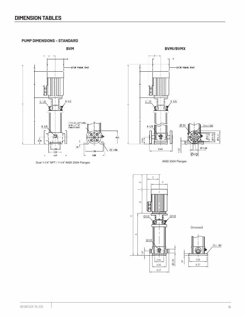
Dual 1-1/4” NPT / 1-1/4” ANSI 250# Flanges
DIMENSION TABLES
PUMP DIMENSIONS – STANDARD
BVM BVMI/BVMX
C
F
E
A
BD
BD
C
F
E
A
2.95
3.94
.75 x .96
3.50
3.94
5.51
2.95
1.34
3.5
4.13
5.51
5.559.84
7.098.66
1.97
1.66
.873.94
.16 x .555.55
7.09
8.27
.55
3.35
1.26
.75 x 1.06
8.27
9.84
.16 x .55
.79 1.38
3
3.945.639.88
7.0611.69
1.25" NPT
.81
NPT
Grooved
Flange 1-1/4” ANSI 250#
Flange 1-1/4” ANSI 300#
ANSI 250# Flanges
16 BE991 (03-15-20)
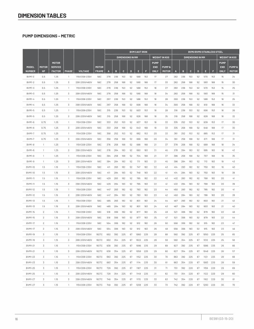
DIMENSION TABLES
PUMP DIMENSIONS – METRIC
MODEL
NUMBER
MOTOR
HP
MOTOR
SERVICE
FACTOR PHASE VOLTAGE
MOTOR
FRAME
BVM CAST IRON BVMI/BVMX STAINLESS STEEL
DIMENSIONS IN MM WEIGHT IN KGS DIMENSIONS IN MM WEIGHT IN KGS
A B C D E F
PUMP
END
ONLY
PUMP &
MOTOR A B C D E F
PUMP
END
ONLY
PUMP &
MOTOR
BVM1-2 0.5 1.25 1 115V/208-230V 56C 279 236 153 52 568 153 17 27 282 236 153 52 570 153 15 24
BVM1-2 0.5 1.25 3 208-230V/460V 56C 279 258 168 52 590 168 17 33 282 258 168 52 593 168 15 30
BVM1-3 0.5 1.25 1 115V/208-230V 56C 279 236 153 52 568 153 18 27 282 236 153 52 570 153 15 25
BVM1-3 0.5 1.25 3 208-230V/460V 56C 279 258 168 52 590 168 18 34 282 258 168 52 593 168 15 31
BVM1-4 0.5 1.25 1 115V/208-230V 56C 297 236 153 52 586 153 18 28 300 236 153 52 588 153 16 25
BVM1-4 0.5 1.25 3 208-230V/460V 56C 297 258 168 52 608 168 18 34 300 258 168 52 610 168 16 32
BVM1-5 0.5 1.25 1 115V/208-230V 56C 315 236 153 52 603 153 19 28 318 236 153 52 606 153 16 26
BVM1-5 0.5 1.25 3 208-230V/460V 56C 315 258 168 52 626 168 19 35 318 258 168 52 628 168 16 32
BVM1-6 0.75 1.25 1 115V/208-230V 56C 333 252 153 52 637 153 19 33 335 252 153 52 639 153 17 30
BVM1-6 0.75 1.25 3 208-230V/460V 56C 333 258 168 52 643 168 19 33 335 258 168 52 646 168 17 30
BVM1-7 0.75 1.25 1 115V/208-230V 56C 358 252 153 52 662 153 20 33 361 252 153 52 665 153 17 31
BVM1-7 0.75 1.25 3 208-230V/460V 56C 358 258 168 52 669 168 20 34 361 258 168 52 671 168 17 31
BVM1-8 1 1.25 1 115V/208-230V 56C 376 258 168 52 686 168 21 37 378 258 168 52 689 168 18 34
BVM1-8 1 1.25 3 208-230V/460V 56C 376 264 183 52 693 183 21 45 378 264 183 52 695 183 18 42
BVM1-9 1 1.25 1 115V/208-230V 56C 394 258 168 52 704 168 21 37 396 258 168 52 707 168 19 35
BVM1-9 1 1.25 3 208-230V/460V 56C 394 264 183 52 711 183 21 45 396 264 183 52 713 183 19 43
BVM1-10 1.5 1.15 1 115V/208-230V 56C 411 283 182 52 747 182 22 43 414 283 182 52 750 182 19 40
BVM1-10 1.5 1.15 3 208-230V/460V 56C 411 284 183 52 748 183 22 41 414 284 183 52 750 183 19 38
BVM1-11 1.5 1.15 1 115V/208-230V 56C 429 283 182 52 765 182 22 43 432 283 182 52 768 182 20 41
BVM1-11 1.5 1.15 3 208-230V/460V 56C 429 284 183 52 765 183 22 41 432 284 183 52 768 183 20 39
BVM1-12 1.5 1.15 1 115V/208-230V 56C 447 283 182 52 783 182 23 44 450 283 182 52 785 182 20 41
BVM1-12 1.5 1.15 3 208-230V/460V 56C 447 284 183 52 783 183 23 42 450 284 183 52 786 183 20 39
BVM1-13 1.5 1.15 1 115V/208-230V 56C 465 283 182 52 801 182 24 44 467 283 182 52 803 182 21 42
BVM1-13 1.5 1.15 3 208-230V/460V 56C 465 284 183 52 801 183 24 43 467 284 183 52 803 183 21 40
BVM1-15 2 1.15 1 115V/208-230V 56C 518 306 182 52 877 182 25 49 521 306 182 52 879 182 22 46
BVM1-15 2 1.15 3 208-230V/460V 56C 518 306 183 52 877 183 25 47 521 306 183 52 879 183 22 44
BVM1-17 2 1.15 1 115V/208-230V 56C 554 306 182 52 912 182 26 50 556 306 182 52 915 182 23 47
BVM1-17 2 1.15 3 208-230V/460V 56C 554 306 183 52 912 183 26 48 556 306 183 52 915 183 23 46
BVM1-19 3 1.15 1 115V/208-230V 182TC 602 392 225 67 1060 225 28 68 592 392 225 67 1050 225 25 65
BVM1-19 3 1.15 3 208-230V/460V 182TC 602 354 225 67 1022 225 28 59 592 354 225 67 1012 225 25 56
BVM1-21 3 1.15 1 115V/208-230V 182TC 638 392 225 67 1096 225 29 69 627 392 225 67 1086 225 26 66
BVM1-21 3 1.15 3 208-230V/460V 182TC 638 354 225 67 1058 225 29 60 627 354 225 67 1048 225 26 57
BVM1-23 3 1.15 1 115V/208-230V 182TC 693 392 225 67 1152 225 30 70 663 392 225 67 1121 225 28 68
BVM1-23 3 1.15 3 208-230V/460V 182TC 693 354 225 67 1114 225 30 61 663 354 220 67 1083 220 28 59
BVM1-25 3 1.15 1 115V/208-230V 182TC 729 392 225 67 1187 225 31 71 701 392 220 67 1159 220 29 69
BVM1-25 3 1.15 3 208-230V/460V 182TC 729 354 225 67 1149 225 31 62 701 354 220 67 1122 220 29 60
BVM1-27 3 1.15 3 208-230V/460V 182TC 749 354 225 67 1170 225 33 63 742 354 220 67 1162 220 30 61
BVM1-27 3 1.15 1 115V/208-230V 182TC 749 392 225 67 1208 225 33 73 742 392 220 67 1200 220 30 70

17 BE991 (03-15-20)
Dual 1-1/4” NPT / 1-1/4” ANSI 250# Flanges
DIMENSION TABLES
BVM BVMI/BVMX
Grooved
NPT
Flange 1-1/4” ANSI 250#
Flange 1-1/4” ANSI 300#
100141
250
180220
1.25" NPT
20
BD
E
A
C
F
BD
E
A
C
F
75
ANSI 250# Flanges

18 BE991 (03-15-20)
DIMENSION TABLES
MODEL
NUMBER
MOTOR
HP
MOTOR
SERVICE
FACTOR PHASE VOLTAGE
MOTOR
FRAME
BVM CAST IRON BVMI/BVMX STAINLESS STEEL
DIMENSIONS IN INCHES WEIGHT IN LBS DIMENSIONS IN INCHES WEIGHT IN LBS
A B C D E F
PUMP
END
ONLY
PUMP &
MOTOR A B C D E F
PUMP
END
ONLY
PUMP &
MOTOR
BVM3-2 0.5 1.25 1 115V/208-230V 56C 11.0 9.3 6.0 2.1 22.4 6.0 38 59 11.1 9.3 6.0 2.1 22.5 6.0 32 53
BVM3-2 0.5 1.25 3 208-230V/460V 56C 11.0 10.2 6.6 2.1 23.2 6.6 38 73 11.1 10.2 6.6 2.1 23.3 6.6 32 67
BVM3-3 0.5 1.25 1 115V/208-230V 56C 11.0 9.3 6.0 2.1 22.4 6.0 39 60 11.1 9.3 6.0 2.1 22.5 6.0 33 54
BVM3-3 0.5 1.25 3 208-230V/460V 56C 11.0 10.2 6.6 2.1 23.2 6.6 39 74 11.1 10.2 6.6 2.1 23.3 6.6 33 68
BVM3-4 0.75 1.25 1 115V/208-230V 56C 11.7 9.9 6.0 2.1 23.7 6.0 40 69 11.8 9.9 6.0 2.1 23.8 6.0 35 64
BVM3-4 0.75 1.25 3 208-230V/460V 56C 11.7 10.2 6.6 2.1 23.9 6.6 40 70 11.8 10.2 6.6 2.1 24.0 6.6 35 65
BVM3-5 1 1.25 1 115V/208-230V 56C 12.6 10.2 6.6 2.1 24.8 6.6 42 77 12.8 10.2 6.6 2.1 25.0 6.6 36 71
BVM3-5 1 1.25 3 208-230V/460V 56C 12.6 10.4 7.2 2.1 25.1 7.2 42 95 12.8 10.4 7.2 2.1 25.3 7.2 36 89
BVM3-6 1 1.25 1 115V/208-230V 56C 13.3 10.2 6.6 2.1 25.5 6.6 43 78 13.5 10.2 6.6 2.1 25.7 6.6 37 72
BVM3-6 1 1.25 3 208-230V/460V 56C 13.3 10.4 7.2 2.1 25.8 7.2 43 96 13.5 10.4 7.2 2.1 26.0 7.2 37 90
BVM3-7 1.5 1.15 1 115V/208-230V 56C 14.0 11.2 7.2 2.1 27.2 7.2 44 90 14.2 11.2 7.2 2.1 27.4 7.2 39 85
BVM3-7 1.5 1.15 3 208-230V/460V 56C 14.0 11.2 7.2 2.1 27.2 7.2 44 86 14.2 11.2 7.2 2.1 27.4 7.2 39 81
BVM3-8 1.5 1.15 1 115V/208-230V 56C 14.8 11.2 7.2 2.1 28.0 7.2 46 92 14.9 11.2 7.2 2.1 28.1 7.2 40 86
BVM3-8 1.5 1.15 3 208-230V/460V 56C 14.8 11.2 7.2 2.1 28.0 7.2 46 88 14.9 11.2 7.2 2.1 28.1 7.2 40 82
BVM3-9 1.5 1.15 1 115V/208-230V 56C 16.1 11.2 7.2 2.1 29.3 7.2 47 93 16.2 11.2 7.2 2.1 29.4 7.2 41 87
BVM3-9 1.5 1.15 3 208-230V/460V 56C 16.1 11.2 7.2 2.1 29.3 7.2 47 89 16.2 11.2 7.2 2.1 29.4 7.2 41 83
BVM3-10 2 1.15 1 115V/208-230V 56C 16.8 12.1 7.2 2.1 30.9 7.2 48 101 16.9 12.1 7.2 2.1 31.0 7.2 42 95
BVM3-10 2 1.15 3 208-230V/460V 56C 16.8 12.1 7.2 2.1 30.9 7.2 48 97 16.9 12.1 7.2 2.1 31.0 7.2 42 91
BVM3-11 2 1.15 1 115V/208-230V 56C 17.5 12.1 7.2 2.1 31.6 7.2 49 102 17.6 12.1 7.2 2.1 31.7 7.2 44 97
BVM3-11 2 1.15 3 208-230V/460V 56C 17.5 12.1 7.2 2.1 31.6 7.2 49 98 17.6 12.1 7.2 2.1 31.7 7.2 44 93
BVM3-12 2 1.15 1 115V/208-230V 56C 18.2 12.1 7.2 2.1 32.3 7.2 51 104 18.3 12.1 7.2 2.1 32.4 7.2 45 98
BVM3-12 2 1.15 3 208-230V/460V 56C 18.2 12.1 7.2 2.1 32.3 7.2 51 100 18.3 12.1 7.2 2.1 32.4 7.2 45 94
BVM3-13 3 1.15 1 115V/208-230V 182TC 19.4 15.4 8.9 2.6 37.4 8.9 54 142 19.6 15.4 8.7 2.6 37.6 8.7 48 136
BVM3-13 3 1.15 3 208-230V/460V 182TC 19.4 13.9 8.9 2.6 36.0 8.9 54 122 19.6 13.9 8.7 2.6 36.2 8.7 48 116
BVM3-15 3 1.15 1 115V/208-230V 182TC 20.9 15.4 8.9 2.6 38.9 8.9 56 144 21.0 15.4 8.7 2.6 39.0 8.7 51 139
BVM3-15 3 1.15 3 208-230V/460V 182TC 20.9 13.9 8.9 2.6 37.5 8.9 56 124 21.0 13.9 8.7 2.6 37.6 8.7 51 119
BVM3-17 3 1.15 1 115V/208-230V 182TC 22.3 15.4 8.9 2.6 40.3 8.9 59 147 22.9 15.4 8.7 2.6 40.9 8.7 53 141
BVM3-17 3 1.15 3 208-230V/460V 182TC 22.3 13.9 8.9 2.6 38.9 8.9 59 127 22.9 13.9 8.7 2.6 39.5 8.7 53 121
BVM3-19 5 1.15 1 208-230V 213TC 24.3 15.5 9.6 3.1 42.9 9.6 62 179 24.5 15.5 9.6 3.1 43.1 9.6 56 173
BVM3-19 5 1.15 3 208-230V/460V 184TC 24.3 13.9 8.9 2.6 40.9 8.9 62 130 24.5 13.9 8.9 2.6 41.1 8.9 56 124
BVM3-21 5 1.15 1 208-230V 213TC 25.8 15.5 9.6 3.1 44.4 9.6 64 181 25.9 15.5 9.6 3.1 44.5 9.6 58 175
BVM3-21 5 1.15 3 208-230V/460V 184TC 25.8 13.9 8.9 2.6 42.4 8.9 64 132 25.9 13.9 8.9 2.6 42.5 8.9 58 126
BVM3-23 5 1.15 1 208-230V 213TC 27.2 15.5 9.6 3.1 45.8 9.6 67 184 27.3 15.5 9.6 3.1 45.9 9.6 61 178
BVM3-23 5 1.15 3 208-230V/460V 184TC 27.2 13.9 8.9 2.6 43.8 8.9 67 135 27.3 13.9 8.9 2.6 43.9 8.9 61 129
BVM3-25 5 1.15 1 208-230V 213TC 28.1 15.5 9.6 3.1 46.7 9.6 69 186 27.8 15.5 9.6 3.1 46.4 9.6 64 181
BVM3-25 5 1.15 3 208-230V/460V 184TC 28.1 13.9 8.9 2.6 44.7 8.9 69 137 27.8 13.9 8.9 2.6 44.4 8.9 64 132

19 BE991 (03-15-20)
Dual 1-1/4” NPT / 1-1/4” ANSI 250# Flanges
DIMENSION TABLES
PUMP DIMENSIONS – STANDARD
BVM BVMI/BVMX
ANSI 250# Flanges
C
F
E
A
BD
BD
C
F
E
A
2.95
3.94
.75 x .96
3.50
3.94
5.51
2.95
1.34
3.5
4.13
5.51
5.559.84
7.098.66
1.97
1.66
.873.94
.16 x .555.55
7.09
8.27
.55
3.35
1.26
.75 x 1.06
8.27
9.84
.16 x .55
.79 1.38
3
3.945.639.88
7.0611.69
1.25" NPT
.81
NPT
Grooved
Flange 1-1/4” ANSI 250#
Flange 1-1/4” ANSI 300#

20 BE991 (03-15-20)
DIMENSION TABLES
PUMP DIMENSIONS – METRIC
MODEL NUMBER
MOTOR HP
MOTOR SAFETY FACTOR PHASE VOLTAGE
MOTOR FRAME
BVM CAST IRON BVMI/BVMX STAINLESS STEEL
DIMENSIONS IN MM WEIGHT IN KGS DIMENSIONS IN MM WEIGHT IN KGS
A B C D E F
PUMP END
ONLYPUMP & MOTOR A B C D E F
PUMP END
ONLYPUMP & MOTOR
BVM3-2 0.5 1.25 1 115V/208-230V 56C 279 236 153 52 568 153 17 27 282 236 153 52 570 153 15 24
BVM3-2 0.5 1.25 3 208-230V/460V 56C 279 258 168 52 590 168 17 33 282 258 168 52 593 168 15 30
BVM3-3 0.5 1.25 1 115V/208-230V 56C 279 236 153 52 568 153 18 27 282 236 153 52 570 153 15 25
BVM3-3 0.5 1.25 3 208-230V/460V 56C 279 258 168 52 590 168 18 34 282 258 168 52 593 168 15 31
BVM3-4 0.75 1.25 1 115V/208-230V 56C 297 252 153 52 601 153 18 31 300 252 153 52 604 153 16 29
BVM3-4 0.75 1.25 3 208-230V/460V 56C 297 258 168 52 608 168 18 32 300 258 168 52 610 168 16 29
BVM3-5 1 1.25 1 115V/208-230V 56C 320 258 168 52 631 168 19 35 325 258 168 52 636 168 16 32
BVM3-5 1 1.25 3 208-230V/460V 56C 320 264 183 52 637 183 19 43 325 264 183 52 642 183 16 40
BVM3-6 1 1.25 1 115V/208-230V 56C 338 258 168 52 648 168 19 35 343 258 168 52 653 168 17 33
BVM3-6 1 1.25 3 208-230V/460V 56C 338 264 183 52 655 183 19 43 343 264 183 52 660 183 17 41
BVM3-7 1.5 1.15 1 115V/208-230V 56C 356 283 182 52 691 182 20 41 361 283 182 52 697 182 17 38
BVM3-7 1.5 1.15 3 208-230V/460V 56C 356 284 183 52 692 183 20 39 361 284 183 52 697 183 17 37
BVM3-8 1.5 1.15 1 115V/208-230V 56C 376 283 182 52 712 182 21 41 378 283 182 52 714 182 18 39
BVM3-8 1.5 1.15 3 208-230V/460V 56C 376 284 183 52 712 183 21 40 378 284 183 52 715 183 18 37
BVM3-9 1.5 1.15 1 115V/208-230V 56C 409 283 182 52 745 182 21 42 411 283 182 52 747 182 19 40
BVM3-9 1.5 1.15 3 208-230V/460V 56C 409 284 183 52 745 183 21 40 411 284 183 52 748 183 19 38
BVM3-10 2 1.15 1 115V/208-230V 56C 427 306 182 52 785 182 22 46 429 306 182 52 788 182 19 43
BVM3-10 2 1.15 3 208-230V/460V 56C 427 306 183 52 785 183 22 44 429 306 183 52 788 183 19 41
BVM3-11 2 1.15 1 115V/208-230V 56C 445 306 182 52 803 182 22 46 447 306 182 52 806 182 20 44
BVM3-11 2 1.15 3 208-230V/460V 56C 445 306 183 52 803 183 22 45 447 306 183 52 806 183 20 42
BVM3-12 2 1.15 1 115V/208-230V 56C 462 306 182 52 821 182 23 47 465 306 182 52 823 182 20 44
BVM3-12 2 1.15 3 208-230V/460V 56C 462 306 183 52 821 183 23 45 465 306 183 52 823 183 20 43
BVM3-13 3 1.15 1 115V/208-230V 182TC 493 392 225 67 951 225 24 64 498 392 220 67 956 220 22 62
BVM3-13 3 1.15 3 208-230V/460V 182TC 493 354 225 67 913 225 24 55 498 354 220 67 918 220 22 53
BVM3-15 3 1.15 1 115V/208-230V 182TC 531 392 225 67 989 225 26 65 533 392 220 67 992 220 23 63
BVM3-15 3 1.15 3 208-230V/460V 182TC 531 354 225 67 951 225 26 56 533 354 220 67 954 220 23 54
BVM3-17 3 1.15 1 115V/208-230V 182TC 566 392 225 67 1025 225 27 67 582 392 220 67 1040 220 24 64
BVM3-17 3 1.15 3 208-230V/460V 182TC 566 354 225 67 987 225 27 58 582 354 220 67 1002 220 24 55
BVM3-19 5 1.15 1 208-230V 213TC 617 394 243 79 1090 243 28 81 622 394 243 79 1095 243 25 78
BVM3-19 5 1.15 3 208-230V/460V 184TC 617 354 225 67 1038 225 28 59 622 354 225 67 1043 225 25 56
BVM3-21 5 1.15 1 208-230V 213TC 655 394 243 79 1128 243 29 82 658 394 243 79 1131 243 26 80
BVM3-21 5 1.15 3 208-230V/460V 184TC 655 354 225 67 1076 225 29 60 658 354 225 67 1078 225 26 57
BVM3-23 5 1.15 1 208-230V 213TC 691 394 243 79 1164 243 30 83 693 394 243 79 1166 243 28 81
BVM3-23 5 1.15 3 208-230V/460V 184TC 691 354 225 67 1111 225 30 61 693 354 225 67 1114 225 28 59
BVM3-25 5 1.15 1 208-230V 213TC 714 394 243 79 1187 243 31 84 706 394 243 79 1179 243 29 82
BVM3-25 5 1.15 3 208-230V/460V 184TC 714 354 226 67 1134 226 31 62 706 354 225 67 1127 225 29 60

21 BE991 (03-15-20)
Dual 1-1/4” NPT / 1-1/4” ANSI 250# Flanges
DIMENSION TABLES
BVM BVMI/BVMX
Grooved
NPT
Flange 1-1/4” ANSI 250#
Flange 1-1/4” ANSI 300#
100141
250
180220
1.25" NPT
20
BD
E
A
C
F
BD
E
A
C
F
75
ANSI 250# Flanges
22 BE991 (03-15-20)
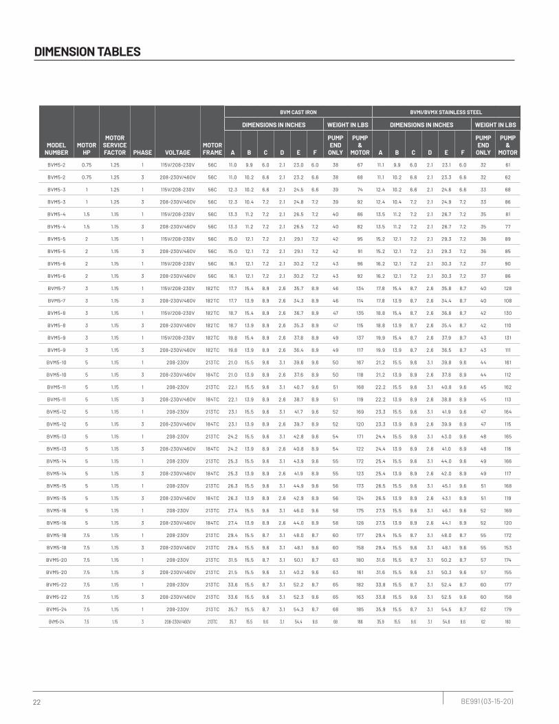
DIMENSION TABLES
MODEL NUMBER
MOTOR HP
MOTOR SERVICE FACTOR PHASE VOLTAGE
MOTOR FRAME
BVM CAST IRON BVMI/BVMX STAINLESS STEEL
DIMENSIONS IN INCHES WEIGHT IN LBS DIMENSIONS IN INCHES WEIGHT IN LBS
A B C D E F
PUMP END
ONLY
PUMP &
MOTOR A B C D E F
PUMP END
ONLY
PUMP &
MOTOR
BVM5-2 0.75 1.25 1 115V/208-230V 56C 11.0 9.9 6.0 2.1 23.0 6.0 38 67 11.1 9.9 6.0 2.1 23.1 6.0 32 61
BVM5-2 0.75 1.25 3 208-230V/460V 56C 11.0 10.2 6.6 2.1 23.2 6.6 38 68 11.1 10.2 6.6 2.1 23.3 6.6 32 62
BVM5-3 1 1.25 1 115V/208-230V 56C 12.3 10.2 6.6 2.1 24.5 6.6 39 74 12.4 10.2 6.6 2.1 24.6 6.6 33 68
BVM5-3 1 1.25 3 208-230V/460V 56C 12.3 10.4 7.2 2.1 24.8 7.2 39 92 12.4 10.4 7.2 2.1 24.9 7.2 33 86
BVM5-4 1.5 1.15 1 115V/208-230V 56C 13.3 11.2 7.2 2.1 26.5 7.2 40 86 13.5 11.2 7.2 2.1 26.7 7.2 35 81
BVM5-4 1.5 1.15 3 208-230V/460V 56C 13.3 11.2 7.2 2.1 26.5 7.2 40 82 13.5 11.2 7.2 2.1 26.7 7.2 35 77
BVM5-5 2 1.15 1 115V/208-230V 56C 15.0 12.1 7.2 2.1 29.1 7.2 42 95 15.2 12.1 7.2 2.1 29.3 7.2 36 89
BVM5-5 2 1.15 3 208-230V/460V 56C 15.0 12.1 7.2 2.1 29.1 7.2 42 91 15.2 12.1 7.2 2.1 29.3 7.2 36 85
BVM5-6 2 1.15 1 115V/208-230V 56C 16.1 12.1 7.2 2.1 30.2 7.2 43 96 16.2 12.1 7.2 2.1 30.3 7.2 37 90
BVM5-6 2 1.15 3 208-230V/460V 56C 16.1 12.1 7.2 2.1 30.2 7.2 43 92 16.2 12.1 7.2 2.1 30.3 7.2 37 86
BVM5-7 3 1.15 1 115V/208-230V 182TC 17.7 15.4 8.9 2.6 35.7 8.9 46 134 17.8 15.4 8.7 2.6 35.8 8.7 40 128
BVM5-7 3 1.15 3 208-230V/460V 182TC 17.7 13.9 8.9 2.6 34.3 8.9 46 114 17.8 13.9 8.7 2.6 34.4 8.7 40 108
BVM5-8 3 1.15 1 115V/208-230V 182TC 18.7 15.4 8.9 2.6 36.7 8.9 47 135 18.8 15.4 8.7 2.6 36.8 8.7 42 130
BVM5-8 3 1.15 3 208-230V/460V 182TC 18.7 13.9 8.9 2.6 35.3 8.9 47 115 18.8 13.9 8.7 2.6 35.4 8.7 42 110
BVM5-9 3 1.15 1 115V/208-230V 182TC 19.8 15.4 8.9 2.6 37.8 8.9 49 137 19.9 15.4 8.7 2.6 37.9 8.7 43 131
BVM5-9 3 1.15 3 208-230V/460V 182TC 19.8 13.9 8.9 2.6 36.4 8.9 49 117 19.9 13.9 8.7 2.6 36.5 8.7 43 111
BVM5-10 5 1.15 1 208-230V 213TC 21.0 15.5 9.6 3.1 39.6 9.6 50 167 21.2 15.5 9.6 3.1 39.8 9.6 44 161
BVM5-10 5 1.15 3 208-230V/460V 184TC 21.0 13.9 8.9 2.6 37.6 8.9 50 118 21.2 13.9 8.9 2.6 37.8 8.9 44 112
BVM5-11 5 1.15 1 208-230V 213TC 22.1 15.5 9.6 3.1 40.7 9.6 51 168 22.2 15.5 9.6 3.1 40.8 9.6 45 162
BVM5-11 5 1.15 3 208-230V/460V 184TC 22.1 13.9 8.9 2.6 38.7 8.9 51 119 22.2 13.9 8.9 2.6 38.8 8.9 45 113
BVM5-12 5 1.15 1 208-230V 213TC 23.1 15.5 9.6 3.1 41.7 9.6 52 169 23.3 15.5 9.6 3.1 41.9 9.6 47 164
BVM5-12 5 1.15 3 208-230V/460V 184TC 23.1 13.9 8.9 2.6 39.7 8.9 52 120 23.3 13.9 8.9 2.6 39.9 8.9 47 115
BVM5-13 5 1.15 1 208-230V 213TC 24.2 15.5 9.6 3.1 42.8 9.6 54 171 24.4 15.5 9.6 3.1 43.0 9.6 48 165
BVM5-13 5 1.15 3 208-230V/460V 184TC 24.2 13.9 8.9 2.6 40.8 8.9 54 122 24.4 13.9 8.9 2.6 41.0 8.9 48 116
BVM5-14 5 1.15 1 208-230V 213TC 25.3 15.5 9.6 3.1 43.9 9.6 55 172 25.4 15.5 9.6 3.1 44.0 9.6 49 166
BVM5-14 5 1.15 3 208-230V/460V 184TC 25.3 13.9 8.9 2.6 41.9 8.9 55 123 25.4 13.9 8.9 2.6 42.0 8.9 49 117
BVM5-15 5 1.15 1 208-230V 213TC 26.3 15.5 9.6 3.1 44.9 9.6 56 173 26.5 15.5 9.6 3.1 45.1 9.6 51 168
BVM5-15 5 1.15 3 208-230V/460V 184TC 26.3 13.9 8.9 2.6 42.9 8.9 56 124 26.5 13.9 8.9 2.6 43.1 8.9 51 119
BVM5-16 5 1.15 1 208-230V 213TC 27.4 15.5 9.6 3.1 46.0 9.6 58 175 27.5 15.5 9.6 3.1 46.1 9.6 52 169
BVM5-16 5 1.15 3 208-230V/460V 184TC 27.4 13.9 8.9 2.6 44.0 8.9 58 126 27.5 13.9 8.9 2.6 44.1 8.9 52 120
BVM5-18 7.5 1.15 1 208-230V 213TC 29.4 15.5 8.7 3.1 48.0 8.7 60 177 29.4 15.5 8.7 3.1 48.0 8.7 55 172
BVM5-18 7.5 1.15 3 208-230V/460V 213TC 29.4 15.5 9.6 3.1 48.1 9.6 60 158 29.4 15.5 9.6 3.1 48.1 9.6 55 153
BVM5-20 7.5 1.15 1 208-230V 213TC 31.5 15.5 8.7 3.1 50.1 8.7 63 180 31.6 15.5 8.7 3.1 50.2 8.7 57 174
BVM5-20 7.5 1.15 3 208-230V/460V 213TC 21.5 15.5 9.6 3.1 40.2 9.6 63 161 31.6 15.5 9.6 3.1 50.3 9.6 57 155
BVM5-22 7.5 1.15 1 208-230V 213TC 33.6 15.5 8.7 3.1 52.2 8.7 65 182 33.8 15.5 8.7 3.1 52.4 8.7 60 177
BVM5-22 7.5 1.15 3 208-230V/460V 213TC 33.6 15.5 9.6 3.1 52.3 9.6 65 163 33.8 15.5 9.6 3.1 52.5 9.6 60 158
BVM5-24 7.5 1.15 1 208-230V 213TC 35.7 15.5 8.7 3.1 54.3 8.7 68 185 35.9 15.5 8.7 3.1 54.5 8.7 62 179
BVM5-24 7.5 1.15 3 208-230V/460V 213TC 35.7 15.5 9.6 3.1 54.4 9.6 68 166 35.9 15.5 9.6 3.1 54.6 9.6 62 160

23 BE991 (03-15-20)
Dual 1-1/4” NPT / 1-1/4” ANSI 250# Flanges
DIMENSION TABLES
PUMP DIMENSIONS – STANDARD
BVM BVMI/BVMX
ANSI 250# Flanges
C
F
E
A
BD
BD
C
F
E
A
2.95
3.94
.75 x .96
3.50
3.94
5.51
2.95
1.34
3.5
4.13
5.51
5.559.84
7.098.66
1.97
1.66
.873.94
.16 x .555.55
7.09
8.27
.55
3.35
1.26
.75 x 1.06
8.27
9.84
.16 x .55
.79 1.38
3
3.945.639.88
7.0611.69
1.25" NPT
.81
NPT
Grooved
Flange 1-1/4” ANSI 250#
Flange 1-1/4” ANSI 300#

24 BE991 (03-15-20)
DIMENSION TABLES
PUMP DIMENSIONS – METRIC
MODEL NUMBER
MOTOR HP
MOTOR SAFETY FACTOR PHASE VOLTAGE
MOTOR FRAME
BVM CAST IRON BVMI/BVMX STAINLESS STEEL
DIMENSIONS IN MM WEIGHT IN KGS DIMENSIONS IN MM WEIGHT IN KGS
A B C D E F
PUMP END
ONLYPUMP & MOTOR A B C D E F
PUMP END
ONLYPUMP & MOTOR
BVM5-2 0.75 1.25 1 115V/208-230V 56C 279 252 153 52 584 153 17 30 282 252 153 52 586 153 15 28
BVM5-2 0.75 1.25 3 208-230V/460V 56C 279 258 168 52 590 168 17 31 282 258 168 52 593 168 15 28
BVM5-3 1 1.25 1 115V/208-230V 56C 312 258 168 52 623 168 18 34 315 258 168 52 625 168 15 31
BVM5-3 1 1.25 3 208-230V/460V 56C 312 264 183 52 629 183 18 42 315 264 183 52 632 183 15 39
BVM5-4 1.5 1.15 1 115V/208-230V 56C 338 283 182 52 674 182 18 39 343 283 182 52 679 182 16 37
BVM5-4 1.5 1.15 3 208-230V/460V 56C 338 284 183 52 674 183 18 37 343 284 183 52 679 183 16 35
BVM5-5 2 1.15 1 115V/208-230V 56C 381 306 182 52 739 182 19 43 386 306 182 52 745 182 16 40
BVM5-5 2 1.15 3 208-230V/460V 56C 381 306 183 52 739 183 19 41 386 306 183 52 745 183 16 39
BVM5-6 2 1.15 1 115V/208-230V 56C 409 306 182 52 767 182 19 43 411 306 182 52 770 182 17 41
BVM5-6 2 1.15 3 208-230V/460V 56C 409 306 183 52 767 183 19 42 411 306 183 52 770 183 17 39
BVM5-7 3 1.15 1 115V/208-230V 182TC 450 392 225 67 908 225 21 61 452 392 220 67 910 220 18 58
BVM5-7 3 1.15 3 208-230V/460V 182TC 450 354 225 67 870 225 21 52 452 354 220 67 873 220 18 49
BVM5-8 3 1.15 1 115V/208-230V 182TC 475 392 225 67 933 225 21 61 478 392 220 67 936 220 19 59
BVM5-8 3 1.15 3 208-230V/460V 182TC 475 354 225 67 895 225 21 52 478 354 220 67 898 220 19 50
BVM5-9 3 1.15 1 115V/208-230V 182TC 503 392 225 67 961 225 22 62 505 392 220 67 964 220 19 59
BVM5-9 3 1.15 3 208-230V/460V 182TC 503 354 225 67 923 225 22 53 505 354 220 67 926 220 19 50
BVM5-10 5 1.15 1 208-230V 213TC 533 394 243 79 1006 243 23 76 538 394 243 79 1012 243 20 73
BVM5-10 5 1.15 3 208-230V/460V 184TC 533 354 225 67 954 225 23 53 538 354 225 67 959 225 20 51
BVM5-11 5 1.15 1 208-230V 213TC 561 394 243 79 1034 243 23 76 564 394 243 79 1037 243 21 74
BVM5-11 5 1.15 3 208-230V/460V 184TC 561 354 225 67 982 225 23 54 564 354 225 67 984 225 21 51
BVM5-12 5 1.15 1 208-230V 213TC 587 394 243 79 1060 243 24 77 592 394 243 79 1065 243 21 74
BVM5-12 5 1.15 3 208-230V/460V 184TC 587 354 225 67 1007 225 24 55 592 354 225 67 1012 225 21 52
BVM5-13 5 1.15 1 208-230V 213TC 615 394 243 79 1088 243 24 77 620 394 243 79 1093 243 22 75
BVM5-13 5 1.15 3 208-230V/460V 184TC 615 354 225 67 1035 225 24 55 620 354 225 67 1040 225 22 53
BVM5-14 5 1.15 1 208-230V 213TC 643 394 243 79 1116 243 25 78 645 394 243 79 1118 243 22 75
BVM5-14 5 1.15 3 208-230V/460V 184TC 643 354 225 67 1063 225 25 56 645 354 225 67 1066 225 22 53
BVM5-15 5 1.15 1 208-230V 213TC 668 394 243 79 1141 243 26 79 673 394 243 79 1146 243 23 76
BVM5-15 5 1.15 3 208-230V/460V 184TC 668 354 225 67 1089 225 26 56 673 354 225 67 1094 225 23 54
BVM5-16 5 1.15 1 208-230V 213TC 696 394 243 79 1169 243 26 79 699 394 243 79 1172 243 24 77
BVM5-16 5 1.15 3 208-230V/460V 184TC 696 354 225 67 1116 225 26 57 699 354 225 67 1119 225 24 54
BVM5-18 7.5 1.15 1 208-230V 213TC 747 394 220 79 1220 220 27 80 747 394 220 79 1220 220 25 78
BVM5-18 7.5 1.15 3 208-230V/460V 213TC 747 395 243 79 1221 243 27 72 747 395 243 79 1221 243 25 69
BVM5-20 7.5 1.15 1 208-230V 213TC 800 394 220 79 1273 220 28 82 803 394 220 79 1276 220 26 79
BVM5-20 7.5 1.15 3 208-230V/460V 213TC 546 395 243 79 1020 243 28 73 803 395 243 79 1277 243 26 70
BVM5-22 7.5 1.15 1 208-230V 213TC 853 394 220 79 1327 220 30 83 859 394 220 79 1332 220 27 80
BVM5-22 7.5 1.15 3 208-230V/460V 213TC 853 395 243 79 1328 243 30 74 859 395 243 79 1333 243 27 72
BVM5-24 7.5 1.15 1 208-230V 213TC 907 394 220 79 1380 220 31 84 912 394 220 79 1385 220 28 81
BVM5-24 7.5 1.15 3 208-230V/460V 213TC 907 395 243 79 1381 243 31 75 912 395 243 79 1386 243 28 73

25 BE991 (03-15-20)
Dual 1-1/4” NPT / 1-1/4” ANSI 250# Flanges
DIMENSION TABLES
BVM BVMI/BVMX
Grooved
NPT
Flange 1-1/4” ANSI 250#
Flange 1-1/4” ANSI 300#
100141
250
180220
1.25" NPT
20
BD
E
A
C
F
BD
E
A
C
F
75
ANSI 250# Flanges

26 BE991 (03-15-20)
DIMENSION TABLES
MODEL NUMBER
MOTOR HP
MOTOR SERVICE FACTOR PHASE VOLTAGE
MOTOR FRAME
BVM CAST IRON BVMI/BVMX STAINLESS STEEL
DIMENSIONS IN INCHES WEIGHT IN LBS DIMENSIONS IN INCHES WEIGHT IN LBS
A B C D E F
PUMP END
ONLYPUMP & MOTOR A B C D E F
PUMP END
ONLYPUMP & MOTOR
BVM10-1 0.75 1.25 1 115V/208-230V 56C 13.7 9.9 6.0 2.1 25.7 6.0 61 90 14.1 9.9 6.0 2.1 26.1 6.0 50 79
BVM10-1 0.75 1.25 3 208-230V/460V 56C 13.7 10.2 6.6 2.1 25.9 6.6 61 91 14.1 10.2 6.6 2.1 26.3 6.6 50 80
BVM10-2 1.5 1.15 1 115V/208-230V 56C 14.3 11.2 7.2 2.1 27.5 7.2 67 113 14.7 11.2 7.2 2.1 27.9 7.2 56 102
BVM10-2 1.5 1.15 3 208-230V/460V 56C 14.3 11.2 7.2 2.1 27.5 7.2 67 109 14.7 11.2 7.2 2.1 27.9 7.2 56 98
BVM10-3 3 1.15 1 115V/208-230V 182TC 16.0 15.4 8.9 2.6 34.0 8.9 74 162 16.4 15.4 8.7 2.6 34.4 8.7 63 151
BVM10-3 3 1.15 3 208-230V/460V 182TC 16.0 13.9 8.9 2.6 32.6 8.9 74 142 16.4 13.9 8.7 2.6 33.0 8.7 63 131
BVM10-4 3 1.15 1 115V/208-230V 182TC 17.4 15.4 8.9 2.6 35.4 8.9 80 168 17.7 15.4 8.7 2.6 35.7 8.7 69 157
BVM10-4 3 1.15 3 208-230V/460V 182TC 17.4 13.9 8.9 2.6 34.0 8.9 80 148 17.7 13.9 8.7 2.6 34.3 8.7 69 137
BVM10-5 5 1.15 1 208-230V 213TC 18.5 15.5 9.6 3.1 37.1 9.6 86 203 18.9 15.5 9.6 3.1 37.5 9.6 75 192
BVM10-5 5 1.15 3 208-230V/460V 184TC 18.5 13.9 8.9 2.6 35.1 8.9 86 154 18.9 13.9 8.9 2.6 35.5 8.9 75 143
BVM10-6 5 1.15 1 208-230V 213TC 19.7 15.5 9.6 3.1 38.3 9.6 92 209 20.1 15.5 9.6 3.1 38.7 9.6 81 198
BVM10-6 5 1.15 3 208-230V/460V 184TC 19.7 13.9 8.9 2.6 36.3 8.9 92 160 20.1 13.9 8.9 2.6 36.7 8.9 81 149
BVM10-7 7.5 1.15 1 208-230V 213TC 20.9 15.5 8.7 3.1 39.5 8.7 98 215 21.2 15.5 8.7 3.1 39.8 8.7 87 204
BVM10-7 7.5 1.15 3 208-230V/460V 213TC 20.9 15.5 9.6 3.1 39.6 9.6 98 196 21.2 15.5 9.6 3.1 39.9 9.6 87 185
BVM10-8 7.5 1.15 1 208-230V 213TC 22.0 15.5 8.7 3.1 40.6 8.7 104 221 22.4 15.5 8.7 3.1 41.0 8.7 93 210
BVM10-8 7.5 1.15 3 208-230V/460V 213TC 22.0 15.5 9.6 3.1 40.7 9.6 104 202 22.4 15.5 9.6 3.1 41.1 9.6 93 191
BVM10-9 7.5 1.15 1 208-230V 213TC 23.2 15.5 8.7 3.1 41.8 8.7 110 227 23.5 15.5 8.7 3.1 42.1 8.7 99 216
BVM10-9 7.5 1.15 3 208-230V/460V 213TC 23.2 15.5 9.6 3.1 41.9 9.6 110 208 23.6 15.5 9.6 3.1 42.3 9.6 99 197
BVM10-10 7.5 1.15 1 208-230V 213TC 24.4 15.5 8.7 3.1 43.0 8.7 116 233 24.8 15.5 8.7 3.1 43.4 8.7 105 222
BVM10-10 7.5 1.15 3 208-230V/460V 213TC 24.4 15.5 9.6 3.1 43.1 9.6 116 214 24.8 15.5 9.6 3.1 43.5 9.6 105 203
BVM10-12 10 1.15 1 208-230V 215TC 26.8 16.6 9.6 3.1 46.5 9.6 129 264 27.2 16.6 9.6 3.1 46.9 9.6 117 252
BVM10-12 10 1.15 3 208-230V/460V 215TC 26.8 15.5 9.6 3.1 45.5 9.6 129 254 27.2 15.5 9.6 3.1 45.9 9.6 117 242
BVM10-14 15 1.15 3 208-230V/460V 254TC 31.0 20.0 12.9 3.8 54.8 12.9 141 416 31.3 20.0 12.9 3.8 55.1 12.9 130 405
BVM10-16 15 1.15 3 208-230V/460V 254TC 33.3 20.0 12.9 3.8 57.1 12.9 153 428 33.7 20.0 12.9 3.8 57.5 12.9 142 417
27 BE991 (03-15-20)
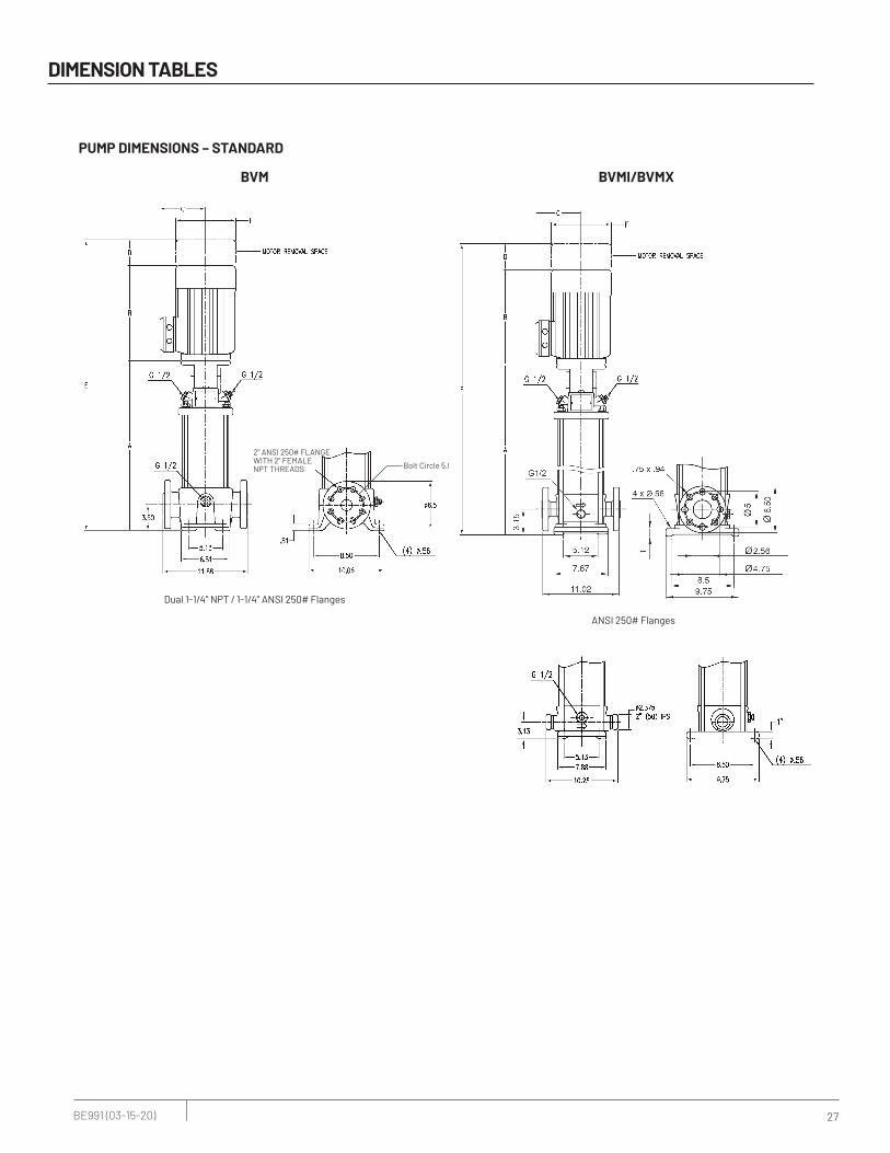
Dual 1-1/4” NPT / 1-1/4” ANSI 250# Flanges
DIMENSION TABLES
PUMP DIMENSIONS – STANDARD
BVM BVMI/BVMX
Bolt Circle 5.0”
2" ANSI 250# FLANGE WITH 2" FEMALE NPT THREADS
ANSI 250# Flanges
28 BE991 (03-15-20)
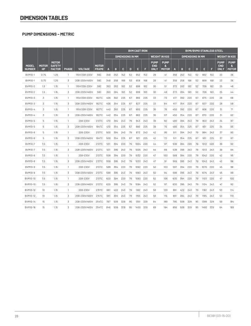
DIMENSION TABLES
PUMP DIMENSIONS – METRIC
MODEL NUMBER
MOTOR HP
MOTOR SAFETY FACTOR PHASE VOLTAGE
MOTOR FRAME
BVM CAST IRON BVMI/BVMX STAINLESS STEEL
DIMENSIONS IN MM WEIGHT IN KGS DIMENSIONS IN MM WEIGHT IN KGS
A B C D E F
PUMP END
ONLY
PUMP &
MOTOR A B C D E F
PUMP END
ONLY
PUMP &
MOTOR
BVM10-1 0.75 1.25 1 115V/208-230V 56C 348 252 153 52 652 153 28 41 358 252 153 52 662 153 23 36
BVM10-1 0.75 1.25 3 208-230V/460V 56C 348 258 168 52 659 168 28 41 358 258 168 52 669 168 23 36
BVM10-2 1.5 1.15 1 115V/208-230V 56C 363 283 182 52 699 182 30 51 373 283 182 52 709 182 25 46
BVM10-2 1.5 1.15 3 208-230V/460V 56C 363 284 183 52 699 183 30 49 373 284 183 52 709 183 25 44
BVM10-3 3 1.15 1 115V/208-230V 182TC 406 392 225 67 865 225 33 73 417 392 220 67 875 220 28 68
BVM10-3 3 1.15 3 208-230V/460V 182TC 406 354 225 67 827 225 33 64 417 354 220 67 837 220 28 59
BVM10-4 3 1.15 1 115V/208-230V 182TC 442 392 225 67 900 225 36 76 450 392 220 67 908 220 31 71
BVM10-4 3 1.15 3 208-230V/460V 182TC 442 354 225 67 862 225 36 67 450 354 220 67 870 220 31 62
BVM10-5 5 1.15 1 208-230V 213TC 470 394 243 79 943 243 39 92 480 394 243 79 953 243 34 87
BVM10-5 5 1.15 3 208-230V/460V 184TC 470 354 225 67 890 225 39 70 480 354 225 67 901 225 34 65
BVM10-6 5 1.15 1 208-230V 213TC 500 394 243 79 973 243 42 95 511 394 243 79 984 243 37 90
BVM10-6 5 1.15 3 208-230V/460V 184TC 500 354 225 67 921 225 42 72 511 354 225 67 931 225 37 67
BVM10-7 7.5 1.15 1 208-230V 213TC 531 394 220 79 1004 220 44 97 538 394 220 79 1012 220 39 92
BVM10-7 7.5 1.15 3 208-230V/460V 213TC 531 395 243 79 1005 243 44 89 538 395 243 79 1013 243 39 84
BVM10-8 7.5 1.15 1 208-230V 213TC 559 394 220 79 1032 220 47 100 569 394 220 79 1042 220 42 95
BVM10-8 7.5 1.15 3 208-230V/460V 213TC 559 395 243 79 1033 243 47 91 569 395 243 79 1043 243 42 86
BVM10-9 7.5 1.15 1 208-230V 213TC 589 394 220 79 1062 220 50 103 597 394 220 79 1070 220 45 98
BVM10-9 7.5 1.15 3 208-230V/460V 213TC 589 395 243 79 1063 243 50 94 599 395 243 79 1074 243 45 89
BVM10-10 7.5 1.15 1 208-230V 213TC 620 394 220 79 1093 220 52 106 630 394 220 79 1103 220 47 100
BVM10-10 7.5 1.15 3 208-230V/460V 213TC 620 395 243 79 1094 243 52 97 630 395 243 79 1104 243 47 92
BVM10-12 10 1.15 1 208-230V 215TC 681 422 243 79 1182 243 58 120 691 422 243 79 1192 243 53 114
BVM10-12 10 1.15 3 208-230V/460V 215TC 681 394 243 79 1155 243 58 115 691 394 243 79 1165 243 53 110
BVM10-14 15 1.15 3 208-230V/460V 254TC 787 509 329 95 1391 329 64 189 795 509 329 95 1399 329 59 184
BVM10-16 15 1.15 3 208-230V/460V 254TC 846 509 329 95 1450 329 69 194 856 509 329 95 1460 329 64 189
29 BE991 (03-15-20)
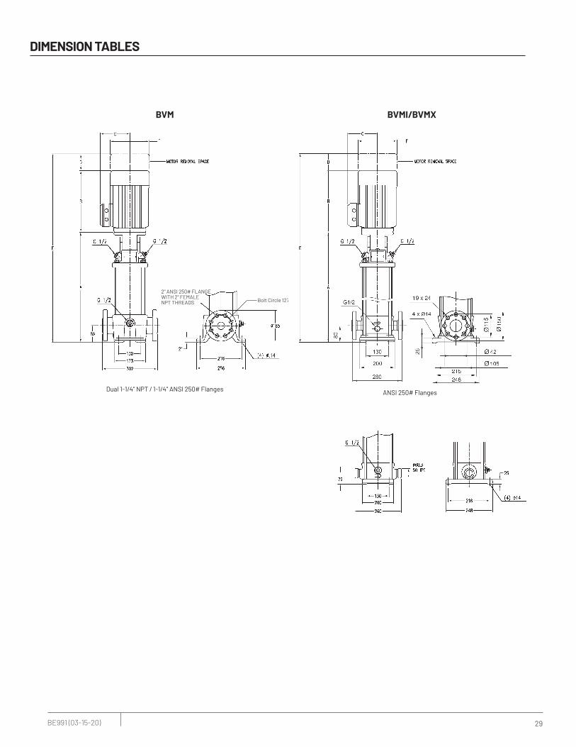
Dual 1-1/4” NPT / 1-1/4” ANSI 250# Flanges
DIMENSION TABLES
BVM BVMI/BVMX
Bolt Circle 127mm
2" ANSI 250# FLANGE WITH 2" FEMALE NPT THREADS
ANSI 250# Flanges

30 BE991 (03-15-20)
Dual 1-1/4” NPT / 1-1/4” ANSI 250# Flanges
DIMENSION TABLES
MODEL
NUMBER
MOTOR
HP
MOTOR
SAFETY
FACTOR PHASE VOLTAGE
MOTOR
FRAME
BVM CAST IRON BVMI/BVMX STAINLESS STEEL
DIMENSIONS IN INCHES WEIGHT IN LBS DIMENSIONS IN INCHES WEIGHT IN LBS
A B C D E F
PUMP
END
ONLY
PUMP &
MOTOR A B C D E F
PUMP
END
ONLY
PUMP &
MOTOR
BVM15-1 2 1.15 1 115V/208-230V 56C 16.3 12.1 7.2 2.1 30.4 7.2 65 118 16.3 12.1 7.2 2.1 30.4 7.2 54 107
BVM15-1 2 1.15 3 208-230V/460V 56C 16.3 12.1 7.2 2.1 30.4 7.2 65 114 16.3 12.1 7.2 2.1 30.4 7.2 54 103
BVM15-2 5 1.15 1 208-230V 213TC 17.0 15.5 9.6 3.1 35.6 9.6 76 193 17.0 15.5 9.6 3.1 35.6 9.6 65 182
BVM15-2 5 1.15 3 208-230V/460V 184TC 17.0 13.9 8.9 2.6 33.6 8.9 76 144 17.0 13.9 8.9 2.6 33.6 8.9 65 133
BVM15-3 7.5 1.15 1 208-230V 213TC 17.4 15.5 8.7 3.1 36.0 8.7 86 203 17.3 15.5 8.7 3.1 35.9 8.7 75 192
BVM15-3 7.5 1.15 3 208-230V/460V 213TC 17.4 15.5 9.6 3.1 36.1 9.6 86 184 17.3 15.5 9.6 3.1 36.0 9.6 75 173
BVM15-4 7.5 1.15 1 208-230V 213TC 20.5 15.5 8.7 3.1 39.1 8.7 96 213 19.1 15.5 8.7 3.1 37.7 8.7 85 202
BVM15-4 7.5 1.15 3 208-230V/460V 213TC 20.5 15.5 9.6 3.1 39.2 9.6 96 194 19.1 15.5 9.6 3.1 37.8 9.6 85 183
BVM15-5 10 1.15 1 208-230V 215TC 22.3 16.6 9.6 3.1 42.0 9.6 106 241 22.2 16.6 9.6 3.1 41.9 9.6 95 230
BVM15-5 10 1.15 3 208-230V/460V 215TC 22.3 15.5 9.6 3.1 41.0 9.6 106 231 22.2 15.5 9.6 3.1 40.9 9.6 95 220
BVM15-6 15 1.15 3 208-230V/460V 254TC 25.9 20.0 12.9 3.8 49.7 12.9 117 392 25.8 20.0 12.9 3.8 49.6 12.9 106 381
BVM15-7 15 1.15 3 208-230V/460V 254TC 27.7 20.0 12.9 3.8 51.5 12.9 127 402 27.6 20.0 12.9 3.8 51.4 12.9 116 391
BVM15-8 15 1.15 3 208-230V/460V 254TC 29.5 20.0 12.9 3.8 53.3 12.9 137 412 29.4 20.0 12.9 3.8 53.2 12.9 126 401
BVM15-9 20 1.15 3 230V/460V 254TC 31.2 16.9 10.3 3.8 51.8 10.3 147 372 31.1 16.9 10.3 3.8 51.7 10.3 136 361
BVM15-10 20 1.15 3 230V/460V 254TC 33.0 16.9 10.3 3.8 53.6 10.3 157 382 32.9 16.9 10.3 3.8 53.5 10.3 146 371
BVM15-12 25 1.15 3 230V/460V 284TSC 38.5 20.0 12.9 3.0 61.5 12.9 177 498 38.4 20.0 12.9 3.0 61.4 12.9 166 487
BVM BVMI/BVMX
Bolt Circle 5.0”
2" ANSI 250# FLANGE WITH 2" FEMALE NPT THREADS
ANSI 250# Flanges

31 BE991 (03-15-20)
Dual 1-1/4” NPT / 1-1/4” ANSI 250# Flanges
DIMENSION TABLES
MODEL
NUMBER
MOTOR
HP
MOTOR
SAFETY
FACTOR PHASE VOLTAGE
MOTOR
FRAME
BVM CAST IRON BVMI/BVMX STAINLESS STEEL
DIMENSIONS IN MM WEIGHT IN KGS DIMENSIONS IN MM WEIGHT IN KGS
A B C D E F
PUMP
END
ONLY
PUMP &
MOTOR A B C D E F
PUMP
END
ONLY
PUMP &
MOTOR
BVM15-1 2 1.15 1 115V/208-230V 56C 414 306 182 52 772 182 29 54 414 306 182 52 772 182 24 48
BVM15-1 2 1.15 3 208-230V/460V 56C 414 306 183 52 772 183 29 52 414 306 183 52 772 183 24 47
BVM15-2 5 1.15 1 208-230V 213TC 432 394 243 79 905 243 34 87 432 394 243 79 905 243 29 82
BVM15-2 5 1.15 3 208-230V/460V 184TC 432 354 225 67 852 225 34 65 432 354 225 67 852 225 29 60
BVM15-3 7.5 1.15 1 208-230V 213TC 442 394 220 79 915 220 39 92 439 394 220 79 912 220 34 87
BVM15-3 7.5 1.15 3 208-230V/460V 213TC 442 395 243 79 916 243 39 83 439 395 243 79 914 243 34 78
BVM15-4 7.5 1.15 1 208-230V 213TC 521 394 220 79 994 220 43 96 485 394 220 79 958 220 38 91
BVM15-4 7.5 1.15 3 208-230V/460V 213TC 521 395 243 79 995 243 43 88 485 395 243 79 959 243 38 83
BVM15-5 10 1.15 1 208-230V 215TC 566 422 243 79 1068 243 48 109 564 422 243 79 1065 243 43 104
BVM15-5 10 1.15 3 208-230V/460V 215TC 566 394 243 79 1040 243 48 105 564 394 243 79 1038 243 43 100
BVM15-6 15 1.15 3 208-230V/460V 254TC 658 509 329 95 1262 329 53 178 655 509 329 95 1259 329 48 173
BVM15-7 15 1.15 3 208-230V/460V 254TC 704 509 329 95 1308 329 58 182 701 509 329 95 1305 329 53 177
BVM15-8 15 1.15 3 208-230V/460V 254TC 749 509 329 95 1353 329 62 187 747 509 329 95 1351 329 57 182
BVM15-9 20 1.15 3 230V/460V 254TC 792 428 263 95 1316 263 67 169 790 428 263 95 1313 263 62 164
BVM15-10 20 1.15 3 230V/460V 254TC 838 428 263 95 1362 263 71 173 836 428 263 95 1359 263 66 168
BVM15-12 25 1.15 3 230V/460V 284TSC 978 507 329 76 1561 329 80 226 975 507 329 76 1559 329 75 221
BVM BVMI/BVMX
Bolt Circle 127mm
2" ANSI 250# FLANGE WITH 2" FEMALE NPT THREADS
ANSI 250# Flanges

32 BE991 (03-15-20)
Dual 1-1/4” NPT / 1-1/4” ANSI 250# Flanges
DIMENSION TABLES
MODEL
NUMBER
MOTOR
HP
MOTOR
SERVICE
FACTOR PHASE VOLTAGE
MOTOR
FRAME
BVM CAST IRON BVMI/BVMX STAINLESS STEEL
DIMENSIONS IN INCHES WEIGHT IN LBS DIMENSIONS IN INCHES WEIGHT IN LBS
A B C D E F
PUMP
END
ONLY
PUMP &
MOTOR A B C D E F
PUMP
END
ONLY
PUMP &
MOTOR
BVM20-1 3 1.15 1 115V/208-230V 182TC 16.8 15.4 8.9 2.6 34.8 8.9 66 154 16.8 15.4 8.7 2.6 34.8 8.7 55 143
BVM20-1 3 1.15 3 208-230V/460V 182TC 16.8 13.9 8.9 2.6 33.4 8.9 66 134 16.8 13.9 8.7 2.6 33.4 8.7 55 123
BVM20-2 5 1.15 1 208-230V 213TC 17.0 15.5 9.6 3.1 35.6 9.6 76 193 17.0 15.5 9.6 3.1 35.6 9.6 65 182
BVM20-2 5 1.15 3 208-230V/460V 184TC 17.0 13.9 8.9 2.6 33.6 8.9 76 144 17.0 13.9 8.9 2.6 33.6 8.9 65 133
BVM20-3 7.5 1.15 1 208-230V 213TC 18.8 15.5 8.7 3.1 37.4 8.7 86 203 18.8 15.5 8.7 3.1 37.4 8.7 75 192
BVM20-3 7.5 1.15 3 208-230V/460V 213TC 18.8 15.5 9.6 3.1 37.5 9.6 86 184 18.8 15.5 9.6 3.1 37.5 9.6 75 173
BVM20-4 10 1.15 1 208-230V 215TC 20.5 16.6 9.6 3.1 40.2 9.6 96 231 20.5 16.6 9.6 3.1 40.2 9.6 85 220
BVM20-4 10 1.15 3 208-230V/460V 215TC 20.5 15.5 9.6 3.1 39.2 9.6 96 221 20.5 15.5 9.6 3.1 39.2 9.6 85 210
BVM20-5 15 1.15 3 208-230V/460V 254TC 24.1 20.0 12.9 3.8 47.9 12.9 107 382 24.1 20.0 12.9 3.8 47.9 12.9 96 371
BVM20-6 15 1.15 3 208-230V/460V 254TC 25.9 20.0 12.9 3.8 49.7 12.9 117 392 25.9 20.0 12.9 3.8 49.7 12.9 106 381
BVM20-7 20 1.15 3 230V/460V 254TC 27.7 16.9 10.3 3.8 48.3 10.3 127 352 27.7 16.9 10.3 3.8 48.3 10.3 116 341
BVM20-8 20 1.15 3 230V/460V 254TC 29.5 16.9 10.3 3.8 50.1 10.3 137 362 29.5 16.9 10.3 3.8 50.1 10.3 126 351
BVM20-10 25 1.15 3 230V/460V 284TSC 35.0 20.0 12.9 3.0 58.0 12.9 157 478 35.0 20.0 12.9 3.0 58.0 12.9 146 467
BVM BVMI/BVMX
Bolt Circle 5.0”
2" ANSI 250# FLANGE WITH 2" FEMALE NPT THREADS
ANSI 250# Flanges
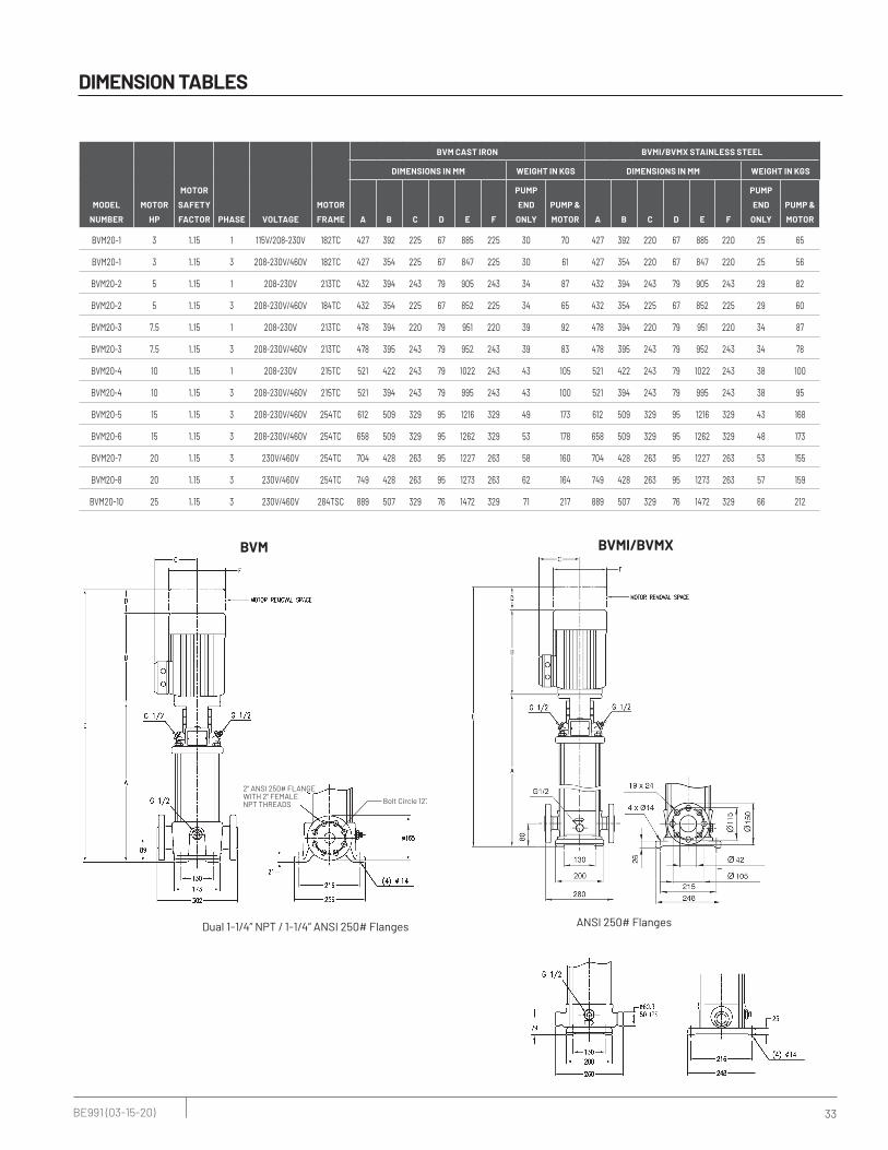
33 BE991 (03-15-20)
Dual 1-1/4” NPT / 1-1/4” ANSI 250# Flanges
DIMENSION TABLES
MODEL
NUMBER
MOTOR
HP
MOTOR
SAFETY
FACTOR PHASE VOLTAGE
MOTOR
FRAME
BVM CAST IRON BVMI/BVMX STAINLESS STEEL
DIMENSIONS IN MM WEIGHT IN KGS DIMENSIONS IN MM WEIGHT IN KGS
A B C D E F
PUMP
END
ONLY
PUMP &
MOTOR A B C D E F
PUMP
END
ONLY
PUMP &
MOTOR
BVM20-1 3 1.15 1 115V/208-230V 182TC 427 392 225 67 885 225 30 70 427 392 220 67 885 220 25 65
BVM20-1 3 1.15 3 208-230V/460V 182TC 427 354 225 67 847 225 30 61 427 354 220 67 847 220 25 56
BVM20-2 5 1.15 1 208-230V 213TC 432 394 243 79 905 243 34 87 432 394 243 79 905 243 29 82
BVM20-2 5 1.15 3 208-230V/460V 184TC 432 354 225 67 852 225 34 65 432 354 225 67 852 225 29 60
BVM20-3 7.5 1.15 1 208-230V 213TC 478 394 220 79 951 220 39 92 478 394 220 79 951 220 34 87
BVM20-3 7.5 1.15 3 208-230V/460V 213TC 478 395 243 79 952 243 39 83 478 395 243 79 952 243 34 78
BVM20-4 10 1.15 1 208-230V 215TC 521 422 243 79 1022 243 43 105 521 422 243 79 1022 243 38 100
BVM20-4 10 1.15 3 208-230V/460V 215TC 521 394 243 79 995 243 43 100 521 394 243 79 995 243 38 95
BVM20-5 15 1.15 3 208-230V/460V 254TC 612 509 329 95 1216 329 49 173 612 509 329 95 1216 329 43 168
BVM20-6 15 1.15 3 208-230V/460V 254TC 658 509 329 95 1262 329 53 178 658 509 329 95 1262 329 48 173
BVM20-7 20 1.15 3 230V/460V 254TC 704 428 263 95 1227 263 58 160 704 428 263 95 1227 263 53 155
BVM20-8 20 1.15 3 230V/460V 254TC 749 428 263 95 1273 263 62 164 749 428 263 95 1273 263 57 159
BVM20-10 25 1.15 3 230V/460V 284TSC 889 507 329 76 1472 329 71 217 889 507 329 76 1472 329 66 212
BVM BVMI/BVMX
Bolt Circle 127mm
2" ANSI 250# FLANGE WITH 2" FEMALE NPT THREADS
ANSI 250# Flanges
34 BE991 (03-15-20)
DIMENSION TABLES
MODEL
NUMBER
MOTOR
HP
MOTOR
SERVICE
FACTOR PHASE VOLTAGE
MOTOR
FRAME
BVM CAST IRON BVMI/BVMX STAINLESS STEEL
DIMENSIONS IN INCHES WEIGHT IN LBS DIMENSIONS IN INCHES WEIGHT IN LBS
A B C D E F
PUMP
END
ONLY
PUMP &
MOTOR A B C D E F
PUMP
END
ONLY
PUMP &
MOTOR
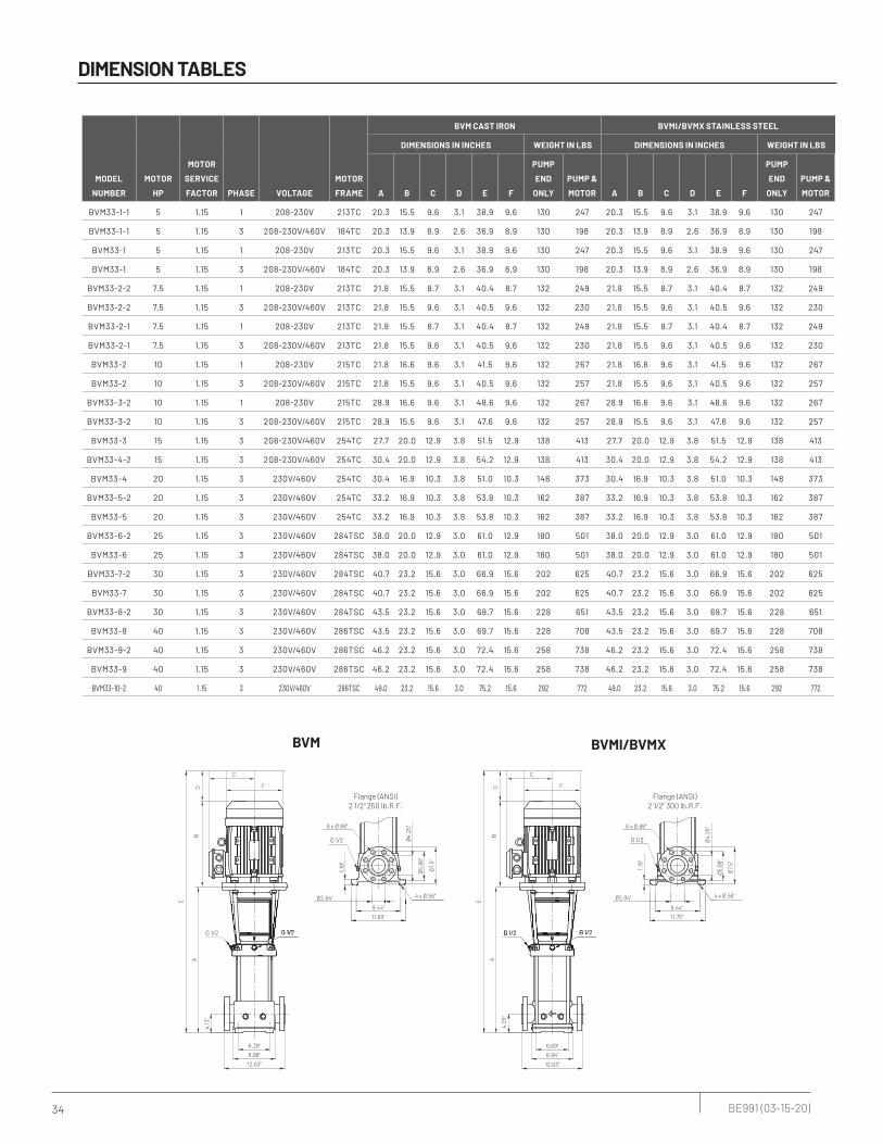
BVM33-1-1 5 1.15 1 208-230V 213TC 20.3 15.5 9.6 3.1 38.9 9.6 130 247 20.3 15.5 9.6 3.1 38.9 9.6 130 247
BVM33-1-1 5 1.15 3 208-230V/460V 184TC 20.3 13.9 8.9 2.6 36.9 8.9 130 198 20.3 13.9 8.9 2.6 36.9 8.9 130 198
BVM33-1 5 1.15 1 208-230V 213TC 20.3 15.5 9.6 3.1 38.9 9.6 130 247 20.3 15.5 9.6 3.1 38.9 9.6 130 247
BVM33-1 5 1.15 3 208-230V/460V 184TC 20.3 13.9 8.9 2.6 36.9 8.9 130 198 20.3 13.9 8.9 2.6 36.9 8.9 130 198
BVM33-2-2 7.5 1.15 1 208-230V 213TC 21.8 15.5 8.7 3.1 40.4 8.7 132 249 21.8 15.5 8.7 3.1 40.4 8.7 132 249
BVM33-2-2 7.5 1.15 3 208-230V/460V 213TC 21.8 15.5 9.6 3.1 40.5 9.6 132 230 21.8 15.5 9.6 3.1 40.5 9.6 132 230
BVM33-2-1 7.5 1.15 1 208-230V 213TC 21.8 15.5 8.7 3.1 40.4 8.7 132 249 21.8 15.5 8.7 3.1 40.4 8.7 132 249
BVM33-2-1 7.5 1.15 3 208-230V/460V 213TC 21.8 15.5 9.6 3.1 40.5 9.6 132 230 21.8 15.5 9.6 3.1 40.5 9.6 132 230
BVM33-2 10 1.15 1 208-230V 215TC 21.8 16.6 9.6 3.1 41.5 9.6 132 267 21.8 16.6 9.6 3.1 41.5 9.6 132 267
BVM33-2 10 1.15 3 208-230V/460V 215TC 21.8 15.5 9.6 3.1 40.5 9.6 132 257 21.8 15.5 9.6 3.1 40.5 9.6 132 257
BVM33-3-2 10 1.15 1 208-230V 215TC 28.9 16.6 9.6 3.1 48.6 9.6 132 267 28.9 16.6 9.6 3.1 48.6 9.6 132 267
BVM33-3-2 10 1.15 3 208-230V/460V 215TC 28.9 15.5 9.6 3.1 47.6 9.6 132 257 28.9 15.5 9.6 3.1 47.6 9.6 132 257
BVM33-3 15 1.15 3 208-230V/460V 254TC 27.7 20.0 12.9 3.8 51.5 12.9 138 413 27.7 20.0 12.9 3.8 51.5 12.9 138 413
BVM33-4-2 15 1.15 3 208-230V/460V 254TC 30.4 20.0 12.9 3.8 54.2 12.9 138 413 30.4 20.0 12.9 3.8 54.2 12.9 138 413
BVM33-4 20 1.15 3 230V/460V 254TC 30.4 16.9 10.3 3.8 51.0 10.3 148 373 30.4 16.9 10.3 3.8 51.0 10.3 148 373
BVM33-5-2 20 1.15 3 230V/460V 254TC 33.2 16.9 10.3 3.8 53.8 10.3 162 387 33.2 16.9 10.3 3.8 53.8 10.3 162 387
BVM33-5 20 1.15 3 230V/460V 254TC 33.2 16.9 10.3 3.8 53.8 10.3 162 387 33.2 16.9 10.3 3.8 53.8 10.3 162 387
BVM33-6-2 25 1.15 3 230V/460V 284TSC 38.0 20.0 12.9 3.0 61.0 12.9 180 501 38.0 20.0 12.9 3.0 61.0 12.9 180 501
BVM33-6 25 1.15 3 230V/460V 284TSC 38.0 20.0 12.9 3.0 61.0 12.9 180 501 38.0 20.0 12.9 3.0 61.0 12.9 180 501
BVM33-7-2 30 1.15 3 230V/460V 284TSC 40.7 23.2 15.6 3.0 66.9 15.6 202 625 40.7 23.2 15.6 3.0 66.9 15.6 202 625
BVM33-7 30 1.15 3 230V/460V 284TSC 40.7 23.2 15.6 3.0 66.9 15.6 202 625 40.7 23.2 15.6 3.0 66.9 15.6 202 625
BVM33-8-2 30 1.15 3 230V/460V 284TSC 43.5 23.2 15.6 3.0 69.7 15.6 228 651 43.5 23.2 15.6 3.0 69.7 15.6 228 651
BVM33-8 40 1.15 3 230V/460V 286TSC 43.5 23.2 15.6 3.0 69.7 15.6 228 708 43.5 23.2 15.6 3.0 69.7 15.6 228 708
BVM33-9-2 40 1.15 3 230V/460V 286TSC 46.2 23.2 15.6 3.0 72.4 15.6 258 738 46.2 23.2 15.6 3.0 72.4 15.6 258 738
BVM33-9 40 1.15 3 230V/460V 286TSC 46.2 23.2 15.6 3.0 72.4 15.6 258 738 46.2 23.2 15.6 3.0 72.4 15.6 258 738
BVM33-10-2 40 1.15 3 230V/460V 286TSC 49.0 23.2 15.6 3.0 75.2 15.6 292 772 49.0 23.2 15.6 3.0 75.2 15.6 292 772
BVM BVMI/BVMX
G 1/2 G 1/2
G 1/2
Flange (ANSI)2 1/2" 250 lb.R.F.
G 1/2 G 1/2
G 1/2
Flange (ANSI)2 1/2" 300 lb.R.F.
REFERENCEREFERENCEREFERENCEREFERENCEREFERENCEREFERENCEREFERENCEREFERENCEREFERENCEREFERENCEREFERENCEREFERENCEREFERENCEREFERENCEREFERENCEREFERENCEREFERENCEREFERENCEREFERENCEREFERENCEREFERENCEREFERENCEREFERENCEREFERENCEREFERENCEREFERENCEREFERENCEREFERENCEREFERENCEREFERENCEREFERENCEREFERENCEREFERENCEREFERENCEREFERENCEREFERENCEREFERENCEREFERENCEREFERENCEREFERENCEREFERENCEREFERENCEREFERENCEREFERENCEREFERENCEREFERENCEREFERENCEREFERENCEREFERENCEREFERENCEREFERENCEREFERENCEREFERENCEREFERENCEREFERENCEREFERENCEREFERENCEREFERENCEREFERENCEREFERENCEREFERENCEREFERENCEREFERENCEREFERENCEREFERENCEREFERENCEREFERENCEREFERENCEREFERENCEREFERENCEREFERENCEREFERENCEREFERENCEREFERENCEREFERENCEREFERENCEREFERENCEREFERENCEREFERENCEREFERENCEREFERENCEREFERENCEREFERENCEREFERENCEREFERENCEREFERENCEREFERENCEREFERENCEREFERENCEREFERENCEREFERENCEREFERENCEREFERENCEREFERENCEREFERENCEREFERENCEREFERENCEREFERENCEREFERENCEREFERENCEREFERENCEREFERENCEREFERENCEREFERENCEREFERENCEREFERENCEREFERENCEREFERENCEREFERENCEREFERENCEREFERENCEREFERENCEREFERENCEREFERENCEREFERENCEREFERENCEREFERENCEREFERENCEREFERENCEREFERENCEREFERENCEREFERENCEREFERENCEREFERENCEREFERENCEREFERENCEREFERENCEREFERENCEREFERENCEREFERENCEREFERENCEREFERENCEREFERENCEREFERENCEREFERENCEREFERENCEREFERENCEREFERENCEREFERENCEREFERENCEREFERENCEREFERENCEREFERENCEREFERENCEREFERENCEREFERENCEG 1/2G 1/2REFERENCEREFERENCEREFERENCEREFERENCEREFERENCEREFERENCEREFERENCEREFERENCEREFERENCEREFERENCEREFERENCEREFERENCEREFERENCEREFERENCEREFERENCEREFERENCEREFERENCEREFERENCEREFERENCEREFERENCEREFERENCEREFERENCEREFERENCEREFERENCEREFERENCEREFERENCEREFERENCEREFERENCEREFERENCEREFERENCEREFERENCEREFERENCEREFERENCEREFERENCEREFERENCEREFERENCEREFERENCEREFERENCEREFERENCEREFERENCEREFERENCEREFERENCEREFERENCEREFERENCEREFERENCEREFERENCEREFERENCEREFERENCEREFERENCEREFERENCEREFERENCEREFERENCEREFERENCEREFERENCEREFERENCEREFERENCEREFERENCEREFERENCEREFERENCEREFERENCEREFERENCEREFERENCEREFERENCEREFERENCEREFERENCEREFERENCEREFERENCEREFERENCEREFERENCEREFERENCEREFERENCEREFERENCEREFERENCEREFERENCEREFERENCEREFERENCEREFERENCEREFERENCEREFERENCEREFERENCEREFERENCEREFERENCEREFERENCEREFERENCEREFERENCEREFERENCEREFERENCEREFERENCEREFERENCEREFERENCEREFERENCEREFERENCEREFERENCEREFERENCEREFERENCEREFERENCEREFERENCEREFERENCEREFERENCEREFERENCEREFERENCEREFERENCEREFERENCEREFERENCEREFERENCEREFERENCEREFERENCEREFERENCEREFERENCEREFERENCEREFERENCEREFERENCEREFERENCEREFERENCEREFERENCEREFERENCEREFERENCEREFERENCEREFERENCEREFERENCEREFERENCEREFERENCEREFERENCEREFERENCEREFERENCEREFERENCEREFERENCEREFERENCEREFERENCEREFERENCEREFERENCEREFERENCEREFERENCEREFERENCEREFERENCEREFERENCEREFERENCEREFERENCEREFERENCEREFERENCEREFERENCEREFERENCEREFERENCEREFERENCEREFERENCEREFERENCEREFERENCEREFERENCEREFERENCEREFERENCEREFERENCEREFERENCEREFERENCEREFERENCEREFERENCEREFERENCEREFERENCEREFERENCEREFERENCEREFERENCEREFERENCEREFERENCEREFERENCEREFERENCEREFERENCEREFERENCEREFERENCEREFERENCEREFERENCEREFERENCEREFERENCEREFERENCEREFERENCEREFERENCEREFERENCEREFERENCEREFERENCEREFERENCEREFERENCEREFERENCEREFERENCEG 1/2G 1/2REFERENCEREFERENCEREFERENCEG 1/2G 1/2
Flange (ANSI)2 1/2" 150 lb.R.F.REFERENCEREFERENCEREFERENCEREFERENCEREFERENCEREFERENCEREFERENCEREFERENCEREFERENCEREFERENCEREFERENCEREFERENCEREFERENCEREFERENCEREFERENCEREFERENCEREFERENCEREFERENCEREFERENCEREFERENCEREFERENCEREFERENCEREFERENCEREFERENCEREFERENCE
6.39"
12.63"
4.13
"
8.88"
6.69"
12.63"
4.25
"
8.94"
1.19
"
Ø2.94"
8 x Ø.88"
Ø4.
25"
Ø5.
88"
Ø7.
5"
9.44"
11.75"
4 x Ø.56"
Ø4.
25"
Ø5.
88"
Ø7.
5"
4 x Ø.56"
9.44"
Ø2.94"
1.19
"
8 x Ø.88"
11.69"
AB
C
D
E
F
AB
C
D
E
F

35 BE991 (03-15-20)
DIMENSION TABLES
MODEL
NUMBER
MOTOR
HP
MOTOR
SAFETY
FACTOR PHASE VOLTAGE
MOTOR
FRAME
BVM CAST IRON BVMI/BVMX STAINLESS STEEL
DIMENSIONS IN MM WEIGHT IN KGS DIMENSIONS IN MM WEIGHT IN KGS
A B C D E F
PUMP
END
ONLY
PUMP &
MOTOR A B C D E F
PUMP
END
ONLY
PUMP &
MOTOR
BVM33-1-1 5 1.15 1 208-230V 213TC 516 394 243 79 989 243 59 112 516 394 243 79 989 243 59 112
BVM33-1-1 5 1.15 3 208-230V/460V 184TC 516 354 225 67 936 225 59 90 516 354 225 67 936 225 59 90
BVM33-1 5 1.15 1 208-230V 213TC 516 394 243 79 989 243 59 112 516 394 243 79 989 243 59 112
BVM33-1 5 1.15 3 208-230V/460V 184TC 516 354 225 67 936 225 59 90 516 354 225 67 936 225 59 90
BVM33-2-2 7.5 1.15 1 208-230V 213TC 554 394 220 79 1027 220 60 113 554 394 220 79 1027 220 60 113
BVM33-2-2 7.5 1.15 3 208-230V/460V 213TC 554 395 243 79 1028 243 60 104 554 395 243 79 1028 243 60 104
BVM33-2-1 7.5 1.15 1 208-230V 213TC 554 394 220 79 1027 220 60 113 554 394 220 79 1027 220 60 113
BVM33-2-1 7.5 1.15 3 208-230V/460V 213TC 554 395 243 79 1028 243 60 104 554 395 243 79 1028 243 60 104
BVM33-2 10 1.15 1 208-230V 215TC 554 422 243 79 1055 243 60 121 554 422 243 79 1055 243 60 121
BVM33-2 10 1.15 3 208-230V/460V 215TC 554 394 243 79 1028 243 60 117 554 394 243 79 1028 243 60 117
BVM33-3-2 10 1.15 1 208-230V 215TC 734 422 243 79 1236 243 60 121 734 422 243 79 1236 243 60 121
BVM33-3-2 10 1.15 3 208-230V/460V 215TC 734 394 243 79 1208 243 60 117 734 394 243 79 1208 243 60 117
BVM33-3 15 1.15 3 208-230V/460V 254TC 704 509 329 95 1308 329 63 187 704 509 329 95 1308 329 63 187
BVM33-4-2 15 1.15 3 208-230V/460V 254TC 772 509 329 95 1376 329 63 187 772 509 329 95 1376 329 63 187
BVM33-4 20 1.15 3 230V/460V 254TC 772 428 263 95 1296 263 67 169 772 428 263 95 1296 263 67 169
BVM33-5-2 20 1.15 3 230V/460V 254TC 843 428 263 95 1367 263 73 176 843 428 263 95 1367 263 73 176
BVM33-5 20 1.15 3 230V/460V 254TC 843 428 263 95 1367 263 73 176 843 428 263 95 1367 263 73 176
BVM33-6-2 25 1.15 3 230V/460V 284TSC 965 507 329 76 1549 329 82 227 965 507 329 76 1549 329 82 227
BVM33-6 25 1.15 3 230V/460V 284TSC 965 507 329 76 1549 329 82 227 965 507 329 76 1549 329 82 227
BVM33-7-2 30 1.15 3 230V/460V 284TSC 1034 589 395 76 1699 395 92 283 1034 589 395 76 1699 395 92 283
BVM33-7 30 1.15 3 230V/460V 284TSC 1034 589 395 76 1699 395 92 283 1034 589 395 76 1699 395 92 283
BVM33-8-2 30 1.15 3 230V/460V 284TSC 1105 589 395 76 1770 395 103 295 1105 589 395 76 1770 395 103 295
BVM33-8 40 1.15 3 230V/460V 286TSC 1105 589 395 76 1770 395 103 321 1105 589 395 76 1770 395 103 321
BVM33-9-2 40 1.15 3 230V/460V 286TSC 1173 589 395 76 1839 395 117 335 1173 589 395 76 1839 395 117 335
BVM33-9 40 1.15 3 230V/460V 286TSC 1173 589 395 76 1839 395 117 335 1173 589 395 76 1839 395 117 335
BVM33-10-2 40 1.15 3 230V/460V 286TSC 1245 589 395 76 1910 395 132 350 1245 589 395 76 1910 395 132 350
BVM BVMI/BVMX
G 1/2 G 1/2
G 1/2
Flange (ANSI)2 1/2" 250 lb.R.F.
G 1/2 G 1/2
G 1/2
Flange (ANSI)2 1/2" 300 lb.R.F.
REFERENCEREFERENCEREFERENCEREFERENCEREFERENCEREFERENCEREFERENCEREFERENCEREFERENCEREFERENCEREFERENCEREFERENCEREFERENCEREFERENCEREFERENCEREFERENCEREFERENCEREFERENCEREFERENCEREFERENCEREFERENCEREFERENCEREFERENCEREFERENCEREFERENCEREFERENCEREFERENCEREFERENCEREFERENCEREFERENCEREFERENCEREFERENCEREFERENCEREFERENCEREFERENCEREFERENCEREFERENCEREFERENCEREFERENCEREFERENCEREFERENCEREFERENCEREFERENCEREFERENCEREFERENCEREFERENCEREFERENCEREFERENCEREFERENCEREFERENCEREFERENCEREFERENCEREFERENCEREFERENCEREFERENCEREFERENCEREFERENCEREFERENCEREFERENCEREFERENCEREFERENCEREFERENCEREFERENCEREFERENCEREFERENCEREFERENCEREFERENCEREFERENCEREFERENCEREFERENCEREFERENCEREFERENCEREFERENCEREFERENCEREFERENCEREFERENCEREFERENCEREFERENCEREFERENCEREFERENCEREFERENCEREFERENCEREFERENCEREFERENCEREFERENCEREFERENCEREFERENCEREFERENCEREFERENCEREFERENCEREFERENCEREFERENCEREFERENCEREFERENCEREFERENCEREFERENCEREFERENCEREFERENCEREFERENCEREFERENCEREFERENCEREFERENCEREFERENCEREFERENCEREFERENCEREFERENCEREFERENCEREFERENCEREFERENCEREFERENCEREFERENCEREFERENCEREFERENCEREFERENCEREFERENCEREFERENCEREFERENCEREFERENCEREFERENCEREFERENCEREFERENCEREFERENCEREFERENCEREFERENCEREFERENCEREFERENCEREFERENCEREFERENCEREFERENCEREFERENCEREFERENCEREFERENCEREFERENCEREFERENCEREFERENCEREFERENCEREFERENCEREFERENCEREFERENCEREFERENCEREFERENCEREFERENCEREFERENCEREFERENCEREFERENCEREFERENCEG 1/2G 1/2REFERENCEREFERENCEREFERENCEREFERENCEREFERENCEREFERENCEREFERENCEREFERENCEREFERENCEREFERENCEREFERENCEREFERENCEREFERENCEREFERENCEREFERENCEREFERENCEREFERENCEREFERENCEREFERENCEREFERENCEREFERENCEREFERENCEREFERENCEREFERENCEREFERENCEREFERENCEREFERENCEREFERENCEREFERENCEREFERENCEREFERENCEREFERENCEREFERENCEREFERENCEREFERENCEREFERENCEREFERENCEREFERENCEREFERENCEREFERENCEREFERENCEREFERENCEREFERENCEREFERENCEREFERENCEREFERENCEREFERENCEREFERENCEREFERENCEREFERENCEREFERENCEREFERENCEREFERENCEREFERENCEREFERENCEREFERENCEREFERENCEREFERENCEREFERENCEREFERENCEREFERENCEREFERENCEREFERENCEREFERENCEREFERENCEREFERENCEREFERENCEREFERENCEREFERENCEREFERENCEREFERENCEREFERENCEREFERENCEREFERENCEREFERENCEREFERENCEREFERENCEREFERENCEREFERENCEREFERENCEREFERENCEREFERENCEREFERENCEREFERENCEREFERENCEREFERENCEREFERENCEREFERENCEREFERENCEREFERENCEREFERENCEREFERENCEREFERENCEREFERENCEREFERENCEREFERENCEREFERENCEREFERENCEREFERENCEREFERENCEREFERENCEREFERENCEREFERENCEREFERENCEREFERENCEREFERENCEREFERENCEREFERENCEREFERENCEREFERENCEREFERENCEREFERENCEREFERENCEREFERENCEREFERENCEREFERENCEREFERENCEREFERENCEREFERENCEREFERENCEREFERENCEREFERENCEREFERENCEREFERENCEREFERENCEREFERENCEREFERENCEREFERENCEREFERENCEREFERENCEREFERENCEREFERENCEREFERENCEREFERENCEREFERENCEREFERENCEREFERENCEREFERENCEREFERENCEREFERENCEREFERENCEREFERENCEREFERENCEREFERENCEREFERENCEREFERENCEREFERENCEREFERENCEREFERENCEREFERENCEREFERENCEREFERENCEREFERENCEREFERENCEREFERENCEREFERENCEREFERENCEREFERENCEREFERENCEREFERENCEREFERENCEREFERENCEREFERENCEREFERENCEREFERENCEREFERENCEREFERENCEREFERENCEREFERENCEREFERENCEREFERENCEREFERENCEREFERENCEREFERENCEREFERENCEREFERENCEREFERENCEREFERENCEREFERENCEREFERENCEREFERENCEG 1/2G 1/2REFERENCEREFERENCEREFERENCEG 1/2G 1/2
Flange (ANSI)2 1/2" 150 lb.R.F.REFERENCEREFERENCEREFERENCEREFERENCEREFERENCEREFERENCEREFERENCEREFERENCEREFERENCEREFERENCEREFERENCEREFERENCEREFERENCEREFERENCEREFERENCEREFERENCEREFERENCEREFERENCEREFERENCEREFERENCEREFERENCEREFERENCEREFERENCEREFERENCEREFERENCE
162
321
105
226
170
321
108
227
30
Ø75
8 x Ø22
Ø10
8
Ø14
9
Ø19
1
238
298
4 x Ø14
Ø10
8
Ø14
9
Ø19
1
4 x Ø14
240
Ø75
30
8 x Ø22
297
AB
C
D
E
F
AB
C
D
E
F
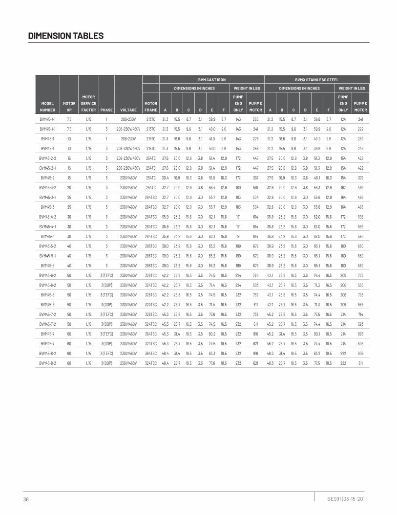
36 BE991 (03-15-20)
DIMENSION TABLES
MODEL
NUMBER
MOTOR
HP
MOTOR
SERVICE
FACTOR PHASE VOLTAGE
BVM CAST IRON BVMX STAINLESS STEEL
DIMENSIONS IN INCHES WEIGHT IN LBS DIMENSIONS IN INCHES WEIGHT IN LBS
MOTOR
FRAME A B C D E F
PUMP
END
ONLY
PUMP &
MOTOR A B C D E F
PUMP
END
ONLY
PUMP &
MOTOR
BVM45-1-1 7.5 1.15 1 208-230V 213TC 21.3 15.5 8.7 3.1 39.9 8.7 143 260 21.2 15.5 8.7 3.1 39.8 8.7 124 241
BVM45-1-1 7.5 1.15 3 208-230V/460V 213TC 21.3 15.5 9.6 3.1 40.0 9.6 143 241 21.2 15.5 9.6 3.1 39.9 9.6 124 222
BVM45-1 10 1.15 1 208-230V 215TC 21.3 16.6 9.6 3.1 41.0 9.6 143 278 21.2 16.6 9.6 3.1 40.9 9.6 124 259
BVM45-1 10 1.15 3 208-230V/460V 215TC 21.3 15.5 9.6 3.1 40.0 9.6 143 268 21.2 15.5 9.6 3.1 39.9 9.6 124 249
BVM45-2-2 15 1.15 3 208-230V/460V 254TC 27.6 20.0 12.9 3.8 51.4 12.9 172 447 27.5 20.0 12.9 3.8 51.3 12.9 154 429
BVM45-2-1 15 1.15 3 208-230V/460V 254TC 27.6 20.0 12.9 3.8 51.4 12.9 172 447 27.5 20.0 12.9 3.8 51.3 12.9 154 429
BVM45-2 15 1.15 3 230V/460V 254TC 30.4 16.9 10.3 3.8 51.0 10.3 172 397 27.5 16.9 10.3 3.8 48.1 10.3 154 379
BVM45-3-2 20 1.15 3 230V/460V 254TC 32.7 20.0 12.9 3.8 56.4 12.9 180 501 32.6 20.0 12.9 3.8 56.3 12.9 162 483
BVM45-3-1 25 1.15 3 230V/460V 284TSC 32.7 20.0 12.9 3.0 55.7 12.9 183 504 32.6 20.0 12.9 3.0 55.6 12.9 164 485
BVM45-3 25 1.15 3 230V/460V 284TSC 32.7 20.0 12.9 3.0 55.7 12.9 183 504 32.6 20.0 12.9 3.0 55.6 12.9 164 485
BVM45-4-2 30 1.15 3 230V/460V 284TSC 35.9 23.2 15.6 3.0 62.1 15.6 191 614 35.8 23.2 15.6 3.0 62.0 15.6 172 595
BVM45-4-1 30 1.15 3 230V/460V 284TSC 35.9 23.2 15.6 3.0 62.1 15.6 191 614 35.8 23.2 15.6 3.0 62.0 15.6 172 595
BVM45-4 30 1.15 3 230V/460V 284TSC 35.9 23.2 15.6 3.0 62.1 15.6 191 614 35.8 23.2 15.6 3.0 62.0 15.6 172 595
BVM45-5-2 40 1.15 3 230V/460V 286TSC 39.0 23.2 15.6 3.0 65.2 15.6 199 679 38.9 23.2 15.6 3.0 65.1 15.6 180 660
BVM45-5-1 40 1.15 3 230V/460V 286TSC 39.0 23.2 15.6 3.0 65.2 15.6 199 679 38.9 23.2 15.6 3.0 65.1 15.6 180 660
BVM45-5 40 1.15 3 230V/460V 286TSC 39.0 23.2 15.6 3.0 65.2 15.6 199 679 38.9 23.2 15.6 3.0 65.1 15.6 180 660
BVM45-6-2 50 1.15 3 (TEFC) 230V/460V 326TSC 42.2 28.8 16.5 3.5 74.5 16.5 224 724 42.1 28.8 16.5 3.5 74.4 16.5 205 705
BVM45-6-2 50 1.15 3 (ODP) 230V/460V 324TSC 42.2 25.7 16.5 3.5 71.4 16.5 224 603 42.1 25.7 16.5 3.5 71.3 16.5 206 585
BVM45-6 50 1.15 3 (TEFC) 230V/460V 326TSC 42.2 28.8 16.5 3.5 74.5 16.5 232 732 42.1 28.8 16.5 3.5 74.4 16.5 206 706
BVM45-6 50 1.15 3 (ODP) 230V/460V 324TSC 42.2 25.7 16.5 3.5 71.4 16.5 232 611 42.1 25.7 16.5 3.5 71.3 16.5 206 585
BVM45-7-2 50 1.15 3 (TEFC) 230V/460V 326TSC 45.3 28.8 16.5 3.5 77.6 16.5 232 732 45.2 28.8 16.5 3.5 77.5 16.5 214 714
BVM45-7-2 50 1.15 3 (ODP) 230V/460V 324TSC 45.3 25.7 16.5 3.5 74.5 16.5 232 611 45.2 25.7 16.5 3.5 74.4 16.5 214 593
BVM45-7 60 1.15 3 (TEFC) 230V/460V 364TSC 45.3 31.4 18.5 3.5 80.2 18.5 232 916 45.2 31.4 18.5 3.5 80.1 18.5 214 898
BVM45-7 60 1.15 3 (ODP) 230V/460V 324TSC 45.3 25.7 18.5 3.5 74.5 18.5 232 621 45.2 25.7 18.5 3.5 74.4 18.5 214 603
BVM45-8-2 60 1.15 3 (TEFC) 230V/460V 364TSC 48.4 31.4 18.5 3.5 83.3 18.5 232 916 48.3 31.4 18.5 3.5 83.2 18.5 222 906
BVM45-8-2 60 1.15 3 (ODP) 230V/460V 324TSC 48.4 25.7 18.5 3.5 77.6 18.5 232 621 48.3 25.7 18.5 3.5 77.5 18.5 222 611

37 BE991 (03-15-20)
DIMENSION TABLES
PUMP DIMENSIONS – STANDARD
BVM BVMX
G 1/2 G 1/2
G 1/2
Flange (ANSI)3" 250 lb.R.F.
G 1/2 G 1/2
G 1/2
Flange (ANSI)3" 250 lb.R.F.
G 1/2 G 1/2 G 1/2
4 x
7.38"
14.38"
5.5"
9.75"7.5"
14.38"
5.5"
9.88"
1.75
"
Ø3.13"
8 x Ø.88"
Ø4.
75"
Ø6.
63"
Ø8.
25"
10.44"
13"
4 x Ø.56"Ø
4.75
"
Ø6.
63"
Ø8.
25"
4 x Ø.56"
10.56"Ø3.13"
1.88
"
8 x Ø.88"
13"
AB
C
D
E
F
AB
C
D
E
F

38 BE991 (03-15-20)
DIMENSION TABLES
BVM/BVMX 45
PUMP DIMENSIONS – METRIC
MODEL
NUMBER
MOTOR
HP
MOTOR
SERVICE
FACTOR PHASE VOLTAGE
MOTOR
FRAME
BVM CAST IRON BVMX STAINLESS STEEL
DIMENSIONS IN MM WEIGHT IN KGS DIMENSIONS IN MM WEIGHT IN KGS
A B C D E F
PUMP
END
ONLY
PUMP &
MOTOR A B C D E F
PUMP
END
ONLY
PUMP &
MOTOR
BVM45-1-1 7.5 1.15 1 208-230V 213TC 541 394 220 79 1014 220 65 118 538 394 220 79 1012 220 56 109
BVM45-1-1 7.5 1.15 3 208-230V/460V 213TC 541 395 243 79 1015 243 65 109 538 395 243 79 1013 243 56 101
BVM45-1 10 1.15 1 208-230V 215TC 541 422 243 79 1043 243 65 126 538 422 243 79 1040 243 56 117
BVM45-1 10 1.15 3 208-230V/460V 215TC 541 394 243 79 1015 243 65 122 538 394 243 79 1012 243 56 113
BVM45-2-2 15 1.15 3 208-230V/460V 254TC 701 509 329 95 1305 329 78 203 699 509 329 95 1303 329 70 195
BVM45-2-1 15 1.15 3 208-230V/460V 254TC 701 509 329 95 1305 329 78 203 699 509 329 95 1303 329 70 195
BVM45-2 15 1.15 3 230V/460V 254TC 772 428 263 95 1296 263 78 180 699 428 263 95 1222 263 70 172
BVM45-3-2 20 1.15 3 230V/460V 254TC 831 507 329 95 1433 329 82 227 828 507 329 95 1431 329 73 219
BVM45-3-1 25 1.15 3 230V/460V 284TSC 831 507 329 76 1414 329 83 229 828 507 329 76 1411 329 74 220
BVM45-3 25 1.15 3 230V/460V 284TSC 831 507 329 76 1414 329 83 229 828 507 329 76 1411 329 74 220
BVM45-4-2 30 1.15 3 230V/460V 284TSC 912 589 395 76 1577 395 87 278 909 589 395 76 1575 395 78 270
BVM45-4-1 30 1.15 3 230V/460V 284TSC 912 589 395 76 1577 395 87 278 909 589 395 76 1575 395 78 270
BVM45-4 30 1.15 3 230V/460V 284TSC 912 589 395 76 1577 395 87 278 909 589 395 76 1575 395 78 270
BVM45-5-2 40 1.15 3 230V/460V 286TSC 991 589 395 76 1656 395 90 308 988 589 395 76 1653 395 82 299
BVM45-5-1 40 1.15 3 230V/460V 286TSC 991 589 395 76 1656 395 90 308 988 589 395 76 1653 395 82 299
BVM45-5 40 1.15 3 230V/460V 286TSC 991 589 395 76 1656 395 90 308 988 589 395 76 1653 395 82 299
BVM45-6-2 50 1.15 3 (TEFC) 230V/460V 326TSC 1072 731 419 89 1892 419 102 328 1069 731 419 89 1889 419 93 320
BVM45-6-2 50 1.15 3 (ODP) 230V/460V 324TSC 1072 653 419 89 1813 419 102 273 1069 653 419 89 1811 419 93 265
BVM45-6 50 1.15 3 (TEFC) 230V/460V 326TSC 1072 731 419 89 1892 419 105 332 1069 731 419 89 1889 419 93 320
BVM45-6 50 1.15 3 (ODP) 230V/460V 324TSC 1072 653 419 89 1813 419 105 277 1069 653 419 89 1811 419 93 265
BVM45-7-2 50 1.15 3 (TEFC) 230V/460V 326TSC 1151 731 419 89 1971 419 105 332 1148 731 419 89 1968 419 97 324
BVM45-7-2 50 1.15 3 (ODP) 230V/460V 324TSC 1151 653 419 89 1892 419 105 277 1148 653 419 89 1890 419 97 269
BVM45-7 60 1.15 3 (TEFC) 230V/460V 364TSC 1151 797 470 89 2036 470 105 415 1148 797 470 89 2034 470 97 407
BVM45-7 60 1.15 3 (ODP) 230V/460V 324TSC 1151 653 470 89 1892 470 105 282 1148 653 470 89 1890 470 97 273
BVM45-8-2 60 1.15 3 (TEFC) 230V/460V 364TSC 1229 797 470 89 2115 470 105 415 1227 797 470 89 2112 470 101 411
BVM45-8-2 60 1.15 3 (ODP) 230V/460V 324TSC 1229 653 470 89 1971 470 105 282 1227 653 470 89 1968 470 101 277
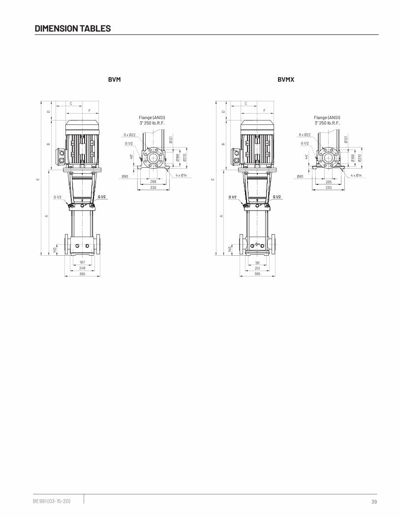
39 BE991 (03-15-20)
DIMENSION TABLES
BVM BVMX
G 1/2 G 1/2
G 1/2
Flange (ANSI)3" 250 lb.R.F.
G 1/2 G 1/2
G 1/2
Flange (ANSI)3" 250 lb.R.F.
G 1/2 G 1/2 G 1/2
4 x
187
365
140
248191
365
140
251
44"
Ø80
8 x Ø22
Ø12
1
Ø16
8
Ø21
0
265
330
4 x Ø14Ø
121
Ø16
8
Ø21
0
4 x Ø14
268Ø80
48"
8 x Ø22
330
AB
C
D
E
F
AB
C
D
E
F

40 BE991 (03-15-20)
DIMENSION TABLES
MODEL
NUMBER
MOTOR
HP
MOTOR
SERVICE
FACTOR PHASE VOLTAGE
MOTOR
FRAME
BVM CAST IRON BVMX STAINLESS STEEL
DIMENSIONS IN INCHES WEIGHT IN LBS DIMENSIONS IN INCHES WEIGHT IN LBS
A B C D E F
PUMP
END
ONLY
PUMP &
MOTOR A B C D E F
PUMP
END
ONLY
PUMP &
MOTOR
BVM64-1-1 10 1.15 1 208-230V 215TC 21.4 16.6 9.6 3.1 41.1 9.6 130 265 21.4 16.6 9.6 3.1 41.1 9.6 115 250
BVM64-1-1 10 1.15 3 208-230V/460V 215TC 21.4 15.5 9.6 3.1 40.1 9.6 130 255 21.4 15.5 9.6 3.1 40.1 9.6 115 240
BVM64-1 15 1.15 3 208-230V/460V 254TC 24.5 20.0 12.9 3.8 48.3 12.9 151 426 24.5 20.0 12.9 3.8 48.3 12.9 136 411
BVM64-2-2 20 1.15 3 230V/460V 254TC 27.8 16.9 10.3 3.8 48.4 10.3 160 385 27.8 16.9 10.3 3.8 48.4 10.3 145 370
BVM64-2-1 20 1.15 3 230V/460V 254TC 27.8 16.9 10.3 3.8 48.4 10.3 160 385 27.8 16.9 10.3 3.8 48.4 10.3 145 370
BVM64-2 25 1.15 3 230V/460V 284TSC 29.8 20.0 12.9 3.0 52.8 12.9 162 483 29.8 20.0 12.9 3.0 52.8 12.9 147 468
BVM64-3-2 30 1.15 3 230V/460V 284TSC 33.0 23.2 15.6 3.0 59.2 15.6 172 595 33.0 23.2 15.6 3.0 59.2 15.6 156 579
BVM64-3-1 40 1.15 3 230V/460V 286TSC 33.0 23.2 15.6 3.0 59.2 15.6 172 652 33.0 23.2 15.6 3.0 59.2 15.6 156 636
BVM64-3 40 1.15 3 230V/460V 286TSC 33.0 23.2 15.6 3.0 59.2 15.6 172 652 33.0 23.2 15.6 3.0 59.2 15.6 156 636
BVM64-4-2 40 1.15 3 230V/460V 286TSC 36.3 23.2 15.6 3.0 62.5 15.6 180 660 36.3 23.2 15.6 3.0 62.5 15.6 156 636
BVM64-4-1 50 1.153
(TEFC)230V/460V 326TSC 36.3 28.8 16.5 3.5 68.6 16.5 198 698 36.3 28.8 16.5 3.5 68.6 16.5 182 682
BVM64-4-1 50 1.15 3 (ODP) 230V/460V 324TSC 36.3 25.7 16.5 3.5 65.5 16.5 198 577 36.3 25.7 16.5 3.5 65.5 16.5 182 561
BVM64-4 50 1.153
(TEFC)230V/460V 326TSC 36.4 28.8 16.5 3.5 68.7 16.5 198 698 36.4 28.8 16.5 3.5 68.7 16.5 182 682
BVM64-4 50 1.15 3 (ODP) 230V/460V 324TSC 36.4 25.7 16.5 3.5 65.6 16.5 198 577 36.4 25.7 16.5 3.5 65.6 16.5 182 561
BVM64-5-2 60 1.153
(TEFC)230V/460V 364TSC 39.6 31.4 18.5 3.5 74.5 18.5 206 890 39.6 31.4 18.5 3.5 74.5 18.5 182 866
BVM64-5-2 60 1.15 3 (ODP) 230V/460V 324TSC 39.6 25.7 18.5 3.5 68.8 18.5 206 595 39.6 25.7 18.5 3.5 68.8 18.5 182 571
BVM BVMX
G 1/2 G 1/2
Flange (ANSI)4" 250 lb.R.F.
G 1/2
G 1/2 G 1/2
G 1/2
Flange (ANSI)4" 250 lb.R.F.
G 1/2 G 1/2 G 1/2
7.38"
14.38"
1.88
"
5.5"
9.75"
Ø3.94"
8 x Ø.88"
Ø5.
88"
Ø7.
88"
Ø10
"
7.5"
14.38"
5.5"
9.88"
10.56"
13"
4 x Ø.56"
1.75
"
Ø3.94"
8 x Ø.88"
Ø5.
88"
Ø7.
88"
Ø10
"
10.44"
13"
4 x Ø.56"
AB
C
D
E
F
AB
C
D
E
F
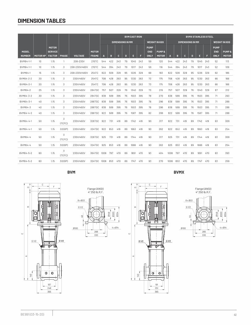
41 BE991 (03-15-20)
DIMENSION TABLES
MODEL
NUMBER MOTOR HP
MOTOR
SERVICE
FACTOR PHASE VOLTAGE
MOTOR
FRAME
BVM CAST IRON BVMX STAINLESS STEEL
DIMENSIONS IN MM WEIGHT IN KGS DIMENSIONS IN MM WEIGHT IN KGS
A B C D E F
PUMP
END
ONLY
PUMP &
MOTOR A B C D E F
PUMP
END
ONLY
PUMP &
MOTOR
BVM64-1-1 10 1.15 1 208-230V 215TC 544 422 243 79 1045 243 59 120 544 422 243 79 1045 243 52 113
BVM64-1-1 10 1.15 3 208-230V/460V 215TC 544 394 243 79 1017 243 59 116 544 394 243 79 1017 243 52 109
BVM64-1 15 1.15 3 208-230V/460V 254TC 622 509 329 95 1226 329 68 193 622 509 329 95 1226 329 62 186
BVM64-2-2 20 1.15 3 230V/460V 254TC 706 428 263 95 1230 263 73 175 706 428 263 95 1230 263 66 168
BVM64-2-1 20 1.15 3 230V/460V 254TC 706 428 263 95 1230 263 73 175 706 428 263 95 1230 263 66 168
BVM64-2 25 1.15 3 230V/460V 284TSC 757 507 329 76 1340 329 73 219 757 507 329 76 1340 329 67 212
BVM64-3-2 30 1.15 3 230V/460V 284TSC 838 589 395 76 1503 395 78 270 838 589 395 76 1503 395 71 263
BVM64-3-1 40 1.15 3 230V/460V 286TSC 838 589 395 76 1503 395 78 296 838 589 395 76 1503 395 71 288
BVM64-3 40 1.15 3 230V/460V 286TSC 838 589 395 76 1503 395 78 296 838 589 395 76 1503 395 71 288
BVM64-4-2 40 1.15 3 230V/460V 286TSC 922 589 395 76 1587 395 82 299 922 589 395 76 1587 395 71 288
BVM64-4-1 50 1.153
(TEFC)230V/460V 326TSC 922 731 419 89 1742 419 90 317 922 731 419 89 1742 419 83 309
BVM64-4-1 50 1.15 3 (ODP) 230V/460V 324TSC 922 653 419 89 1663 419 90 262 922 653 419 89 1663 419 83 254
BVM64-4 50 1.153
(TEFC)230V/460V 326TSC 925 731 419 89 1744 419 90 317 925 731 419 89 1744 419 83 309
BVM64-4 50 1.15 3 (ODP) 230V/460V 324TSC 925 653 419 89 1666 419 90 262 925 653 419 89 1666 419 83 254
BVM64-5-2 60 1.153
(TEFC)230V/460V 364TSC 1006 797 470 89 1891 470 93 404 1006 797 470 89 1891 470 83 393
BVM64-5-2 60 1.15 3 (ODP) 230V/460V 324TSC 1006 653 470 89 1747 470 93 270 1006 653 470 89 1747 470 83 259
BVM BVMX
G 1/2 G 1/2
Flange (ANSI)4" 250 lb.R.F.
G 1/2
G 1/2 G 1/2
G 1/2
Flange (ANSI)4" 250 lb.R.F.
G 1/2 G 1/2 G 1/2
187
365
48
140
248
Ø100
8 x Ø22
Ø14
9
Ø20
0
Ø25
4
191
365
140
251
268
330
4 x Ø14
44
Ø100
8 x Ø22
Ø14
9
Ø20
0
Ø25
4
265
330
4 x Ø14
AB
C
D
E
F
AB
C
D
E
F
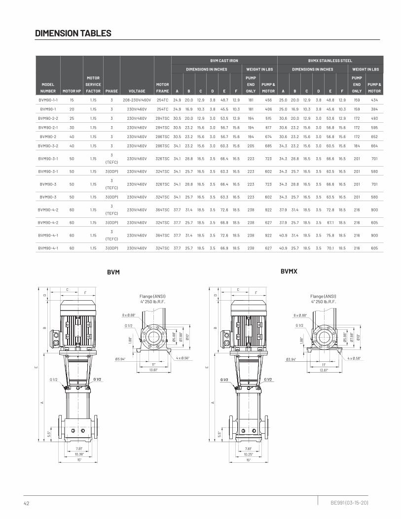
42 BE991 (03-15-20)
DIMENSION TABLES
MODEL
NUMBER MOTOR HP
MOTOR
SERVICE
FACTOR PHASE VOLTAGE
MOTOR
FRAME
BVM CAST IRON BVMX STAINLESS STEEL
DIMENSIONS IN INCHES WEIGHT IN LBS DIMENSIONS IN INCHES WEIGHT IN LBS
A B C D E F
PUMP
END
ONLY
PUMP &
MOTOR A B C D E F
PUMP
END
ONLY
PUMP &
MOTOR
BVM90-1-1 15 1.15 3 208-230V/460V 254TC 24.9 20.0 12.9 3.8 48.7 12.9 181 456 25.0 20.0 12.9 3.8 48.8 12.9 159 434
BVM90-1 20 1.15 3 230V/460V 254TC 24.9 16.9 10.3 3.8 45.5 10.3 181 406 25.0 16.9 10.3 3.8 45.6 10.3 159 384
BVM90-2-2 25 1.15 3 230V/460V 284TSC 30.5 20.0 12.9 3.0 53.5 12.9 194 515 30.6 20.0 12.9 3.0 53.6 12.9 172 493
BVM90-2-1 30 1.15 3 230V/460V 284TSC 30.5 23.2 15.6 3.0 56.7 15.6 194 617 30.6 23.2 15.6 3.0 56.8 15.6 172 595
BVM90-2 40 1.15 3 230V/460V 286TSC 30.5 23.2 15.6 3.0 56.7 15.6 194 674 30.6 23.2 15.6 3.0 56.8 15.6 172 652
BVM90-3-2 40 1.15 3 230V/460V 286TSC 34.1 23.2 15.6 3.0 60.3 15.6 205 685 34.3 23.2 15.6 3.0 60.5 15.6 184 664
BVM90-3-1 50 1.153
(TEFC)230V/460V 326TSC 34.1 28.8 16.5 3.5 66.4 16.5 223 723 34.3 28.8 16.5 3.5 66.6 16.5 201 701
BVM90-3-1 50 1.15 3 (ODP) 230V/460V 324TSC 34.1 25.7 16.5 3.5 63.3 16.5 223 602 34.3 25.7 16.5 3.5 63.5 16.5 201 580
BVM90-3 50 1.153
(TEFC)230V/460V 326TSC 34.1 28.8 16.5 3.5 66.4 16.5 223 723 34.3 28.8 16.5 3.5 66.6 16.5 201 701
BVM90-3 50 1.15 3 (ODP) 230V/460V 324TSC 34.1 25.7 16.5 3.5 63.3 16.5 223 602 34.3 25.7 16.5 3.5 63.5 16.5 201 580
BVM90-4-2 60 1.153
(TEFC)230V/460V 364TSC 37.7 31.4 18.5 3.5 72.6 18.5 238 922 37.9 31.4 18.5 3.5 72.8 18.5 216 900
BVM90-4-2 60 1.15 3 (ODP) 230V/460V 324TSC 37.7 25.7 18.5 3.5 66.9 18.5 238 627 37.9 25.7 18.5 3.5 67.1 18.5 216 605
BVM90-4-1 60 1.153
(TEFC)230V/460V 364TSC 37.7 31.4 18.5 3.5 72.6 18.5 238 922 40.9 31.4 18.5 3.5 75.8 18.5 216 900
BVM90-4-1 60 1.15 3 (ODP) 230V/460V 324TSC 37.7 25.7 18.5 3.5 66.9 18.5 238 627 40.9 25.7 18.5 3.5 70.1 18.5 216 605
BVM BVMX
G 1/2 G 1/2
G 1/2
Flange (ANSI)4" 250 lb.R.F.
G 1/2 G 1/2
G 1/2
Flange (ANSI)4" 250 lb.R.F.
G 1/2 G 1/2 G 1/2
7.81"
15"
5.5"
10.38"
1.88
"
Ø3.94"
8 x Ø.88"
Ø5.
88"
Ø7.
88"
Ø10
"
11"
13.61"
4 x Ø.56"
1.88
"
Ø3.94"
8 x Ø.88"
Ø5.
88"
Ø7.
88"
Ø10
"
11"
13.61"
4 x Ø.56"
7.81"
15"
5.5"
10.25"
AB
C
D
E
F
AB
C
D
E
F

43 BE991 (03-15-20)
DIMENSION TABLES
MODEL
NUMBER
MOTOR
HP
MOTOR
SERVICE
FACTOR PHASE VOLTAGE
MOTOR
FRAME
BVM CAST IRON BVMX STAINLESS STEEL
DIMENSIONS IN MM WEIGHT IN KGS DIMENSIONS IN MM WEIGHT IN KGS
A B C D E F
PUMP
END
ONLY
PUMP &
MOTOR A B C D E F
PUMP
END
ONLY
PUMP &
MOTOR
BVM90-1-1 15 1.15 3 208-230V/460V 254TC 632 509 329 95 1236 329 82 207 635 509 329 95 1239 329 72 197
BVM90-1 20 1.15 3 230V/460V 254TC 632 428 263 95 1156 263 82 184 635 428 263 95 1158 263 72 174
BVM90-2-2 25 1.15 3 230V/460V 284TSC 775 507 329 76 1358 329 88 234 777 507 329 76 1361 329 78 224
BVM90-2-1 30 1.15 3 230V/460V 284TSC 775 589 395 76 1440 395 88 280 777 589 395 76 1442 395 78 270
BVM90-2 40 1.15 3 230V/460V 286TSC 775 589 395 76 1440 395 88 306 777 589 395 76 1442 395 78 296
BVM90-3-2 40 1.15 3 230V/460V 286TSC 866 589 395 76 1531 395 93 311 871 589 395 76 1536 395 83 301
BVM90-3-1 50 1.15 3 (TEFC) 230V/460V 326TSC 866 731 419 89 1686 419 101 328 871 731 419 89 1691 419 91 318
BVM90-3-1 50 1.15 3 (ODP) 230V/460V 324TSC 866 653 419 89 1608 419 101 273 871 653 419 89 1613 419 91 263
BVM90-3 50 1.15 3 (TEFC) 230V/460V 326TSC 866 731 419 89 1686 419 101 328 871 731 419 89 1691 419 91 318
BVM90-3 50 1.15 3 (ODP) 230V/460V 324TSC 866 653 419 89 1608 419 101 273 871 653 419 89 1613 419 91 263
BVM90-4-2 60 1.15 3 (TEFC) 230V/460V 364TSC 958 797 470 89 1843 470 108 418 963 797 470 89 1848 470 98 408
BVM90-4-2 60 1.15 3 (ODP) 230V/460V 324TSC 958 653 470 89 1699 470 108 284 963 653 470 89 1704 470 98 274
BVM90-4-1 60 1.15 3 (TEFC) 230V/460V 364TSC 958 797 470 89 1843 470 108 418 1039 797 470 89 1924 470 98 408
BVM90-4-1 60 1.15 3 (ODP) 230V/460V 324TSC 958 653 470 89 1699 470 108 284 1039 653 470 89 1780 470 98 274
BVM BVMX
G 1/2 G 1/2
G 1/2
Flange (ANSI)4" 250 lb.R.F.
G 1/2 G 1/2
G 1/2
Flange (ANSI)4" 250 lb.R.F.
G 1/2 G 1/2 G 1/2
198
381
140
264
48
Ø100
8 x Ø22
Ø14
9
Ø20
0
Ø25
4
279
346
4 x Ø14
47
Ø100
8 x Ø22
Ø14
9
Ø20
0
Ø25
4279
346
4 x Ø14
198
381
140
260
AB
C
D
E
F
AB
C
D
E
F
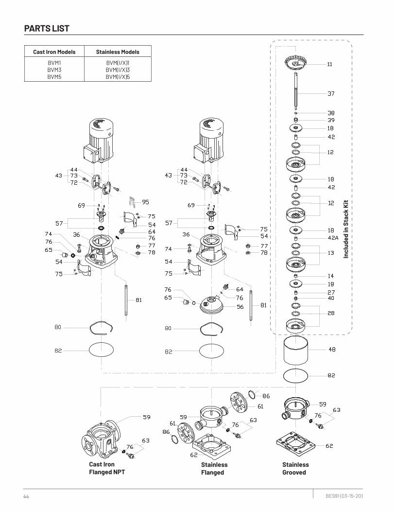
44 BE991 (03-15-20)
Cast IronFlanged NPT
StainlessFlanged
StainlessGrooved
Incl
uded
in S
tack
Kit
Cast Iron Models Stainless Models
BVM1BVM3BVM5
BVM(I/X)1BVM(I/X)3BVM(I/X)5
PARTS LIST

45 BE991 (03-15-20)
COMPONENT BVM1, BVM3 BVMI1, BVMX1, BVMI3, BVMX3 BVM5 BVMI5, BVMX5
11 Discharge Discharge Discharge Discharge
12 Diffuser, Normal Diffuser, Normal Diffuser, Normal Diffuser, Normal
13 Diffuser, with Bearing Diffuser, with Bearing Diffuser, with Bearing Diffuser, with Bearing
14 Bearing Bearing Bearing Bearing
18 Impeller Impeller Impeller Impeller
27 Clamp Clamp Clamp Clamp
28 Diffuser, Bottom Diffuser, Bottom Diffuser, Bottom Diffuser, Bottom
36 Motor Stool Motor Stool Motor Stool Motor Stool
37 Shaft Shaft Shaft Shaft
38 Stack Washer Stack Washer Stack Washer Stack Washer
39 Bushing Bushing Bushing Bushing
40 Bolt, shaft Bolt, shaft Bolt, shaft Bolt, shaft
42 Spacer Spacer Spacer Spacer
42A Spacer Spacer Spacer Spacer
42B Spacer Spacer Spacer Spacer
42C Spacer Spacer Spacer Spacer
43 Coupling Assembly Coupling Assembly Coupling Assembly Coupling Assembly
44 Coupling Half Coupling Half Coupling Half Coupling Half
48 Sleeve Sleeve Sleeve Sleeve
54 Coupling Guard Coupling Guard Coupling Guard Coupling Guard
56 n/a Pump Head n/a Pump Head
57 Mechanical Seal Assembly Mechanical Seal Assembly Mechanical Seal Assembly Mechanical Seal Assembly
59 Base Base Base Base
61 n/a Connecting Flange n/a Connecting Flange
62 n/a Base Plate n/a Base Plate
63 Drain Plug Drain Plug Drain Plug Drain Plug
64 Vent Plug Vent Plug Vent Plug Vent Plug
65 Pump Head Plug Pump Head Plug Pump Head Plug Pump Head Plug
69 Screw, Mechanical Seal Screw, Mechanical Seal Screw, Mechanical Seal Screw, Mechanical Seal
72 Shaft Pin Shaft Pin Shaft Pin Shaft Pin
73 Bolt, Coupling Bolt, Coupling Bolt, Coupling Bolt, Coupling
74 Bolt, Motor Bolt, Motor Bolt, Motor Bolt, Motor
75 Screw, Coupling Guard Screw, Coupling Guard Screw, Coupling Guard Screw, Coupling Guard
76 O-ring, Vent & Drain Plug O-ring, Vent & Drain Plug O-ring, Vent & Drain Plug O-ring, Vent & Drain Plug
77 Staybolt Nut Staybolt Nut Staybolt Nut Staybolt Nut
78 Staybolt Washer Staybolt Washer Staybolt Washer Staybolt Washer
80 Spring Washer Spring Washer Spring Washer Spring Washer
81 Staybolt Staybolt Staybolt Staybolt
82 O-ring, Sleeve O-ring, Sleeve O-ring, Sleeve O-ring, Sleeve
86 n/a Flange Retaining Ring n/a Flange Retaining Ring
95 Stack Height Gauge Stack Height Gauge Stack Height Gauge Stack Height Gauge
PARTS LIST

46 BE991 (03-15-20)
Cast Iron,Flanged NPT
StainlessFlanged
StainlessGrooved
Incl
uded
in S
tack
Kit
CAST IRON MODELS STAINLESS MODELS
BVM10BVM15BVM20
BVM(I/X)10BVM(I/X)15BVM(I/X)20
PARTS LIST

47 BE991 (03-15-20)
COMPONENT BVM10 BVMI10, BVMX10 BVM15, BVM20 BVMI/X15, BVMI/X20
11 Discharge Discharge Discharge Discharge
12 Diffuser, Normal Diffuser, Normal Diffuser, Normal Diffuser, Normal
13 Diffuser, with Bearing Diffuser, with Bearing Diffuser, with Bearing Diffuser, with Bearing
14 Bearing Bearing Bearing Bearing
18 Impeller Impeller Impeller Impeller
24 Wear Ring Wear Ring Wear Ring Wear Ring
25 Wear Ring Retainer Wear Ring Retainer Wear Ring Retainer Wear Ring Retainer
27 Clamp Clamp Clamp Clamp
28 Diffuser, Bottom Diffuser, Bottom Diffuser, Bottom Diffuser, Bottom
30 Strap Retainer Strap Retainer Strap Retainer Strap Retainer
36 Motor Stool Motor Stool Motor Stool Motor Stool
37 Shaft Shaft Shaft Shaft
38 Stack Washer Stack Washer Stack Washer Stack Washer
39 Bushing Bushing Bushing Bushing
40 Nut, shaft Nut, shaft Nut, shaft Nut, shaft
42 Spacer Spacer Spacer Spacer
42A Spacer Spacer Spacer Spacer
42B Spacer Spacer Spacer Spacer
42C Spacer Spacer Spacer Spacer
43 Coupling Assembly Coupling Assembly Coupling Assembly Coupling Assembly
44 Coupling Half Coupling Half Coupling Half Coupling Half
47 Strap Strap Strap Strap
48 Sleeve Sleeve Sleeve Sleeve
50 Motor Stool Adapter Motor Stool Adapter Motor Stool Adapter Motor Stool Adapter
54 Coupling Guard Coupling Guard Coupling Guard Coupling Guard
56 n/a Pump Head n/a Pump Head
57 Mechanical Seal Assembly Mechanical Seal Assembly Mechanical Seal Assembly Mechanical Seal Assembly
59 Base Base Base Base
61 n/a Connecting Flange n/a Connecting Flange
62 n/a Base Plate n/a Base Plate
63 Drain Plug Drain Plug Drain Plug Drain Plug
64 Vent Plug Vent Plug Vent Plug Vent Plug
65 Pump Head Plug Pump Head Plug Pump Head Plug Pump Head Plug
66 O-ring, Mechanical Seal O-ring, Mechanical Seal O-ring, Mechanical Seal O-ring, Mechanical Seal
69 Screw, Mechanical Seal Screw, Mechanical Seal Screw, Mechanical Seal Screw, Mechanical Seal
70 Bolt, strap Bolt, strap Bolt, strap Bolt, strap
71 Washer, strap Washer, strap Washer, strap Washer, strap
72 Shaft Pin Shaft Pin Shaft Pin Shaft Pin
73 Bolt, Coupling Bolt, Coupling Bolt, Coupling Bolt, Coupling
74 Bolt, Motor Bolt, Motor Bolt, Motor Bolt, Motor
75 Screw, Coupling Guard Screw, Coupling Guard Screw, Coupling Guard Screw, Coupling Guard
76 O-ring, Vent & Drain Plug O-ring, Vent & Drain Plug O-ring, Vent & Drain Plug O-ring, Vent & Drain Plug
77 Staybolt Nut Staybolt Nut Staybolt Nut Staybolt Nut
78 Staybolt Washer Staybolt Washer Staybolt Washer Staybolt Washer
80 Stack Bumper Stack Bumper Stack Bumper Stack Bumper
81 Staybolt Staybolt Staybolt Staybolt
82 O-ring, Sleeve O-ring, Sleeve O-ring, Sleeve O-ring, Sleeve
83 O-ring, Drain Plug O-ring, Drain Plug O-ring, Drain Plug O-ring, Drain Plug
86 n/a Flange Retaining Ring n/a Flange Retaining Ring
95 Stack Height Gauge Stack Height Gauge Stack Height Gauge Stack Height Gauge
PARTS LIST

48 BE991 (03-15-20)
Cast IronFlanged
StainlessFlanged
Incl
uded
in S
tack
Kit
Incl
uded
in S
tack
Kit
CAST IRON MODELS STAINLESS MODELS
BVM33BVM45BVM64BVM90
BVM(I/X)33BVM(X)45BVM(X)64BVM(X)90
PARTS LIST
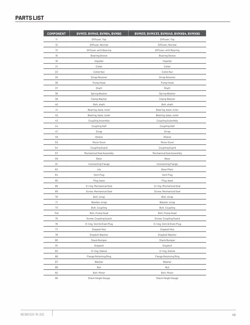
49 BE991 (03-15-20)
COMPONENT BVM33, BVM45, BVM64, BVM90 BVMI33, BVMX33, BVMX45, BVMX64, BVMX90
11 Diffuser, Top Diffuser, Top
12 Diffuser, Normal Diffuser, Normal
13 Diffuser, with Bearing Diffuser, with Bearing
16 Bearing Sleeve Bearing Sleeve
18 Impeller Impeller
21 Collet Collet
22 Collet Nut Collet Nut
30 Strap Retainer Strap Retainer
36 Pump Head Pump Head
37 Shaft Shaft
38 Spring Washer Spring Washer
39 Clamp Washer Clamp Washer
40 Bolt, shaft Bolt, shaft
41 Bearing, base, inner Bearing, base, inner
42 Bearing, base, outer Bearing, base, outer
43 Coupling Assembly Coupling Assembly
44 Coupling Half Coupling Half
47 Strap Strap
48 Sleeve Sleeve
53 Motor Stool Motor Stool
54 Coupling Guard Coupling Guard
57 Mechanical Seal Assembly Mechanical Seal Assembly
59 Base Base
61 Connecting Flange Connecting Flange
62 n/a Base Plate
64 Vent Plug Vent Plug
65 Plug, base Plug, base
66 O-ring, Mechanical Seal O-ring, Mechanical Seal
69 Screw, Mechanical Seal Screw, Mechanical Seal
70 Bolt, strap Bolt, strap
71 Washer, strap Washer, strap
73 Bolt, Coupling Bolt, Coupling
74A Bolt, Pump Head Bolt, Pump Head
75 Screw, Coupling Guard Screw, Coupling Guard
76 O-ring, Vent & Drain Plug O-ring, Vent & Drain Plug
77 Staybolt Nut Staybolt Nut
78 Staybolt Washer Staybolt Washer
80 Stack Bumper Stack Bumper
81 Staybolt Staybolt
82 O-ring, Sleeve O-ring, Sleeve
86 Flange Retaining Ring Flange Retaining Ring
87 Washer Washer
88 Nut Nut
92 Bolt, Motor Bolt, Motor
95 Stack Height Gauge Stack Height Gauge
PARTS LIST

50 BE991 (03-15-20)
TROUBLESHOOTING
SYMPTOM CAUSE
Pump does not operate.
1. Check that unit is securely plugged into outlet, or wired to controller or switch box.
2. Check to be sure you have electrical power and ensure that the piggyback plugs are tight.
3. Check that liquid fluid level is high enough to activate switch or controller.
4. Check to be sure that 1/8" (3 mm) vent hole in discharge pipe is not plugged.
5. Check for blockage in pump inlet, impeller, check valve or discharge pipe.
6. Disconnect the pump from the power source for a minimum of 30 minutes to allow the motor to cool and to protect yourself from sudden starts.
See Warning above. Check for the cause of overheating: pump running dry because the float switch is caught up on something; inlet pipe is plugged; outlet pipe is plugged
7. Motor windings may be open. Take unit to authorized service center.
Pump fails to empty sump.
1. Be sure all valves in discharge pipe are fully open.
2. Clean out discharge pipe and check valve.
3. Check for blockage in pump inlet or impeller.
4. Pump not sized properly. A higher capacity pump may be require.
Pump will not shutoff.1. Check switch or controller automatic floats for proper operation and location. See Installation
section for switch/controller instructions.
2. If pump is completely inoperative or continues to malfunction, consult your local serviceman.
TROUBLESHOOTING
Risk of electrical shock and possible unexpected starts. Disconnect all power to the pump before servicing or working on
pump. Make sure that power is locked out and that pump cannot be accidentally started.

51 BE991 (03-15-20)
WARRANTY
Limited WarrantyBERKELEY warrants to the original consumer purchaser (“Purchaser” or “You”) of the products listed below, that they will be free from defects in material and workmanship for the Warranty Period shown below.
Product Warranty Period
Water Systems:
Water Systems Products — jet pumps, small centrifugal pumps, submersible pumps and related accessories
whichever occurs first: 12 months from date of original installation, or 18 months from date of manufacture
Pro-Source™ Composite Tanks 5 years from date of original installation
Pro-Source™ Steel Pressure Tanks 5 years from date of original installation
Pro-Source™ Epoxy-Lined Tanks 3 years from date of original installation
Sump/Sewage/Effluent Products12 months from date of original installation, or 18 months from date of manufacture
Agricultural/Commercial:
Centrifugals – close-coupled motor drive, frame mount, SAE mount, engine drive, VMS, SSCX, SSHM, solids handling, submersible solids handling
12 months from date of original installation, or 24 months from date of manufacture
Submersible Turbines, 6” diameter and larger12 months from date of original installation, or 24 months from date of manufacture
Our limited warranty will not apply to any product that, in our sole judgement, has been subject to negligence, misapplication, improper installation, or improper maintenance. Without limiting the foregoing, operating a three phase motor with single phase power through a phase converter will void the warranty. Note also that three phase motors must be protected by three-leg, ambient compensated, extra-quick trip overload relays of the recommended size or the warranty is void.Your only remedy, and BERKELEY’s only duty, is that BERKELEY repair or replace defective products (at BERKELEY’s choice). You must pay all labor and shipping charges associated with this warranty and must request warranty service through the installing dealer as soon as a problem is discovered. No request for service will be accepted if received after the Warranty Period has expired. This warranty is not transferable.BERKELEY SHALL NOT BE LIABLE FOR ANY CONSEQUENTIAL, INCIDENTAL, OR CONTINGENT DAMAGES WHATSOEVER.THE FOREGOING LIMITED WARRANTIES ARE EXCLUSIVE AND IN LIEU OF ALL OTHER EXPRESS AND IMPLIED WARRANTIES, INCLUDING BUT NOT LIMITED TO IMPLIED WARRANTIES OF MERCHANTABILITY AND FITNESS FOR A PARTICULAR PURPOSE. THE FOREGOING LIMITED WARRANTIES SHALL NOT EXTEND BEYOND THE DURATION PROVIDED HEREIN.Some states do not allow the exclusion or limitation of incidental or consequential damages or limitations on the duration of an implied warranty, so the above limitations or exclusions may not apply to You. This warranty gives You specific legal rights and You may also have other rights which vary from state to state.This Limited Warranty is effective June 1, 2011 and replaces all undated warranties and warranties dated before June 1, 2011.
In the U.S.: BERKELEY, 293 Wright St., Delavan, WI 53115 In Canada: 269 Trillium Dr., Kitchener, Ontario N2G 4W5

For a detailed list of where Pentair trademarks are registered, please visit www.pentair.com/en/registrations.html. Pentair trademarks and logos are owned by Pentair plc or its affiliates. Third party registered and unregistered trademarks and logos are the property of their respective owners. Because we are continuously improving our products and services, Pentair reserves the right to change specifications without prior notice. Pentair is an equal opportunity employer.
BE991 (03-15-20) ©2020 Pentair. All Rights Reserved.
293 WRIGHT STREET | DELAVAN, WI 53115 | PH: 866-973-6835 | ORDERS FAX: 800-321-8793 | PENTAIR.COM/BERKELEY


![BVM-20E1U/20E1E BVM-14F1U/14F1E BVM-14E1U/14E1E BVM …20operating%20manual[1].pdf · (urbain extérieur) et E4 (environnement EMC contrôlé ex. studio de télévision). Für Kunden](https://img.pdfslide.us/doc/110x75/5e7c88b68c57e3573824d1a6/bvm-20e1u20e1e-bvm-14f1u14f1e-bvm-14e1u14e1e-bvm-20operating20manual1pdf.jpg)