Embed Size (px)
Citation preview

MODEL 1004 TYPE Y OR ZRAPID EXCHANGE® PURGING SYSTEM
PROCESS AUTOMATION
INSTALLATION AND OPERATION MANUAL

Model 1004 Installation and Operation Manual
2
Par
t No.
512
003
Dra
win
g N
o. 1
29-0
203a
03/
09
Table of Contents
Page 2 System Purpose and Description Purpose,Systemdescription,Importantnotes
Page 3 Identifying Your System Definesspecificfeaturesofthesystem
Page 3 General Information System&materialspecifications,Spareparts,Tools
&testequipment,Systemaccessories
Page 4 Enclosure and Device Design Designrequirements,Adjacentenclosures,Device
ventilation,Temperaturelimitations
Page 5 Installation Overview Installationdiagram
Page 6 Getting Started Establishingconnectionsizes,Determiningenclosure
inlet&outletconnectionlocations
Page 7 System Mounting LH,RH,TM,BM&WMconfigurations,FM&PM
configurations
Page 8 Hardware Mounting Requiredenclosureprotectionvent,Warning
nameplates
Page 9 Mounting Plate Dimensions Mountingplatedimensiondiagrams
Page 11 Pneumatic Tubing Requirements Protectivegassupplyrequirements,Pneumatic
connectionrequirements
Page 12 Tubing Installation LH,RH,TM,BM,WM,FM&PMtubing
configurations
Page 13 Tubing Connection Diagrams LH,RH,TM,BM,WM,FM,&PMconfiguration
connectionpoints,Pneumaticdiagram
Page 14 Electrical Supply Requirements Wiringrequirements,Enclosurepower&alarmsignal,
Enclosurewiringmethods&connections
Page 15 Conduit Installation Electrical&WPSstyleconduitandconnectionparts
Page 16 Set-Up Procedure ClassIpurgingset-up
Page 17 Operating Sequence ClassIpurgingoperation
Page 18 Troubleshooting Procedures Troubleshootingchart
Page 19 Warranty and Liability Statement Warrantynotes,Generalterms,Limitations
Page 20 Customer notes
Page 22 System Maintenance Regularmaintenance,Long-termmaintenance,
Maintenanceschedule
Page 23 Systems identification & application information
Purpose and Description
PurposePepperl+Fuchs'BebcoEPSSystemallowstheuseofgeneral-purposeornonratedelectricalorelectronicdevices,withexceptiontodevicesthatproduceexcessiveheat,utilizecombustiblegas,orexposearcingcontactstothehazardousatmosphere,inNEMA(NationalElectricalManufacturersAssociation)4or12enclosuresintheplaceofexplosionproofNEMA7enclosures.Otherpurposesincludeheat,moistureanddustcontaminationprevention.
DescriptionModel1004isaRapidExchangepurgingsystemthatoperatesonasupplyofcompressedinstrumentairorinertgas.Itregulatesandmonitorspressurewithinoneormoresealed(protected)enclosures,inordertorapidlyremoveandpreventflammablevaporaccumulationwithintheenclosure(s).Thesystemaccomplishesfourairexchangesandmaintainsa"safe"(0.25")pressureononeormoreenclosuresnotexceedingatotalvolumeof200cubicfeet.AnEPV-4enclosureprotectionventisrequiredforproperoperation.Thisprocessreducesthehazardous(classified)arearatingwithintheenclosure(s),inaccordancewiththeNEC-NFPA70,Article500,NFPA496andISA2.4.
Important NotesOne(1)permanentfilecopyandone(1)operationscopyofthismanualmustbestudiedandretainedbytheoperatorofthissystem.User’sagentsareresponsiblefortransferringthismanualtotheuser,priortostart-up.
Thecontentsofthismanualhavebeenarrangedtoallowtheuseofthisproductasastand-alonedeviceonequipmentandenclosuressuppliedbytheuseroritsagents.Themanual’sparametersencompassacombinationofbothNationalFireProtectionAssociation(NFPA)requirementsandPepperl+Fuchs,Inc.requirements.Pepperl+FuchsthereforeacknowledgestheuseofNFPA496asaguideline,thatwehaveenhancedcertainNFPArequirementsandthatadditionalinformationhasbeencompiledtocompletethisdocument.Themanualisintendedasacompleteguideandmustbeconsidered,unlessspecificallystatedotherwise,thatalldirectivescontainedhereinarerequirementsforsafe,practicalandefficientuseofthisproduct.
Thissystemisnotintendedforusetoprotectenclosuresordevicesthatcontainignitableconcentrationsofgasesorvapors.Thisexclusiongenerallyappliestoprocessorproductanalyzingsystemsequipment.
All specifications are subject to change without notice.

Model 1004 Installation and Operation Manual
3
Par
t No.
512
003
Dra
win
g N
o. 1
29-0
203a
03/
09Identifying Your System
Thisenclosureprotectionsystemisofferedinvariousstyles.Forproperinstallationandoperation,examinethesystemmodelnumbernameplatetoidentifythesystemstyle,areaclassification,andtype,asnotedbelow.
General Information
System SpecificationsSystemdimensions: Seepages9&10Shippingweight(lbs.): LPS-15,WPS-23Operatingtemp.range: -20°Fto+120°FSupplypressurerange: 80-120psimax.
Whenusingtheoptionalinlinefilter,max.supplypressureis80psiCapacity&filtration: 8.5oz.40micronsSupplyrequirements: CleanairorinertgasSafepressuresetpoint: 0.25"Safepressureflowrate: **0.1-3.5SCFHExchangepressure: *3"-5"Exchangeflowrate: **30SCFM/1800SCFHExchangetime: 1minute/7.5ft3
Systemsupplyport: 1/2"FPTEnclosuresupplyfitting: 1/2"tubefittingEnclosurereferencefitting: 1/4"tubefittingSwitchsetting(WPS&WPSAonly): 0.15"±0.02"WPS&WPSApressureswitchwiring: 1/2"FPTSwitchcontactratings:WPSStyle: 120VAC@15AmpsWPSAStyle: ***120/220VAC,24VDC@10Amps, 125VDC@50mA
* Enclosureintegritydeterminesactualflowandpressure**Withregulatorsetto80psimin.duringexchange***Supplyvoltages24VDCand240VACavailableuponrequest
Exchangeflowratingisbasedonsafetyfactorsconsideredafterextensivefactorytestinganddoesnotreflectactualflow.Flowwasmeasuredupstreamofsystemwithanelectronicflowmeterona5ft3enclosure.Thesystemwasinstalledwithtubingthatexceededthemaximumallowablelinearlengthandquantityofbendslistedinthismanualforsystemsupply,enclosuresupplyandenclosurereferenceconnections.ThesystemwastestedinconjunctionwiththeEPV-4-SA-00enclosureprotectionvent,mounteddirectlyonthetestenclosure.
ABS Traceable Certified Exchange Flow Measurements with System regulator set at 80 psi, ambient temperature of 75° F
120psisupplypressure: 48.38scfm/2902.99scfh100psisupplypressure: 47.58scfm/2855.34scfh
Material SpecificationsRegulatorbody: Zincw/enamelfinishRegulatorhandle: PolycarbonateEnclosurepressuregauge: Aluminumw/enamelfinishRapidExchangegauge: Polycase&brasstubeTubefittings: 316SSforgedbodyTubing: 316SS1/4".035weldedSystemnameplates: SilkscreenedLexan®&SSFastenerhardware: Aluminum&stainlesssteelMountingplate: 31614ga#3brushSSEXPpressureswitchbody: Anodizedcastalum.Enclosurewarningnameplate: SilkscreenedSS
Lexan®isaregisteredtrademarkoftheGeneralElectricCompany
Recommended Spare PartsQty Description Part#(supercedes)1 Enclosurepressureindicator-CI 510023(001000)1 Systemfilteredregulator 510074(002140)1 RapidExchangepressuregauge 510081(002310)1 Enclosurepressurecontrolvalvebody 510145(003840)1 RapidExchangecontrolvalvebody-PM 510149(003860)1 RapidExchangecontrolvalvebody 510155(003940)1 Installation&operationmanual 129-02031 GroupC-Dpressureswitch-CI 510044(001080)1 GroupA-Dpressureswitch-CI 510045(001085)1 Enclosurewarningnameplate-CI 513008(EWN-1
Pleasecallandreferencetheabovepartnumberforcurrentsparepartspricing.Immediatepricingisavailabletoallconfirmedcustomers.
Installation Tools & Testing Equipment1/2"chuckdrill
Completesetofdrillbits
11/2"conduitknockoutpunchor1.875"holesaw
Completesetoftubing,conduitbending,instrumentfittingandelectricalcraftsmanhandtools
0-10"differentialpressuregaugeornanometer(connectedtotheprotectedenclosuretomeasuremaximumpressure)
1004 - LPS - CI - YZ - LH - ##
Series Model NumberSystem Style LPS - less pressure switch WPS - with pressure switch WPSA - with pressure switchArea Classifi cation CI - Class I AreaSystem Type YZ - Div. 1 to Div. 2, Div. 2 to NonhazardousMounting Confi guration LH - left hand left side of enclosure RH - right hand right side of enclosure TM - top mount top of enclosure BM - bottom mount bottom of enclosure WM - wall mount wall surface FM - frame mount external frame or rack PM - panel mount enclosure surface cutout (Not available in WPS Style)
## - Additional factory installed accessories
Confidential according to ISO 16016
sheet
respons.
approved
norm 1 of 1
scale: 1:1
Label for 1004-WPSA-CI Type Y or Z
date: 2004-Feb-03Only valid as long as released in EDM or with a valid production documentation!
Twinsburg1004 WPSA UL Y or Z ID NP SS
125-0833Achange notice.
Dieses Dokument enthält sicherheitsrelevante Angaben. Es darf nicht ohne Absprache mit dem Normenfachmann geändert werden!
This document contains safety-relevant information. It must not be altered without the authorization of the norm expert!
TECHNICAL INFORMATION:
POLYCARB 0.01”MUST BE UL/CSA APPROVED
BLACK COPY ON WHITE BACKGROUNDFULL INFORMATION PERTAINING TO PRINT FONTS,DIMENSIONS AND COLOR SCHEMES ARE CONTAINED INTHIS COREL DRAW (.CDR) FILENAME UNDER DRAWINGNUMBER 125-0833A
LABEL MATERIAL:
ADHESIVE:
COLOR:
NOTE:
US.JMB
US.SSJ
US.WDB150-0355
2.50
1.50
SCALE = 1X
SCALE = 2X
All dimensions are in inches.All outside corners R=0.13
Tolerances: 2-place dec. +/- .01
APPROVED BY FM APPROVALS AS ASSOCIATED TYPE Y & Z PRESSURIZATION CONTROL
EQUIPMENT FOR USE IN HAZARDOUS LOCATIONS. REDUCES THE INTERNAL AREA
OF A CONNECTED ENCLOSURE IN ACCORDANCE WITH DRAWING NUMBER 1004-IOM.
APPROVED BY FM APPROVALS AS ASSOCIATED TYPE Y & Z PRESSURIZATION CONTROL
EQUIPMENT FOR USE IN HAZARDOUS LOCATIONS. REDUCES THE INTERNAL AREA
OF A CONNECTED ENCLOSURE IN ACCORDANCE WITH DRAWING NUMBER 1004-IOM.
LABEL P/N: 510938
REDUCES INTERNAL AREA CLASSIFICATION AS FOLLOWS:TYPE Y: CL. I, DIV. 1, GR. A-D / ZONE 1, GR. IIB+H2 TO DIV. 2 / ZONE 2
TYPE Z: CL. I, DIV. 2, GR. A-D / ZONE 2, GR. IIB+H2 TO NONHAZARDOUS
REDUCES INTERNAL AREA CLASSIFICATION AS FOLLOWS:TYPE Y: CL. I, DIV. 1, GR. A-D / ZONE 1, GR. IIB+H2 TO DIV. 2 / ZONE 2
TYPE Z: CL. I, DIV. 2, GR. A-D / ZONE 2, GR. IIB+H2 TO NONHAZARDOUS
Model 1004-WPSA-CI Type Y or Z
Model 1004-WPSA-CI Type Y or Z
C
LASSIFIED
®
C
LASSIFIED
®
PURGE CONTROL FOR USE IN HAZARDOUS LOCATIONS IN ACCORDANCE WITH THE NATIONAL FIRE
PROTECTION ASSOCIATION STANDARD FOR PURGED AND PRESSURIZED ENCLOSURES FOR ELECTRICAL
EQUIPMENT NFPA 496-1996 4S11
PURGE CONTROL FOR USE IN HAZARDOUS LOCATIONS IN ACCORDANCE WITH THE NATIONAL FIRE
PROTECTION ASSOCIATION STANDARD FOR PURGED AND PRESSURIZED ENCLOSURES FOR ELECTRICAL
EQUIPMENT NFPA 496-1996 4S11
200 CUBIC FEET MAXIMUM ENCLOSURE VOLUME
200 CUBIC FEET MAXIMUM ENCLOSURE VOLUME
Released EDM checkout 2008-JUL-17

Model 1004 Installation and Operation Manual
4
Par
t No.
512
003
Dra
win
g N
o. 1
29-0
203a
03/
09
Model 1004 System AccessoriesEnclosure Protection Vents(onerequiredwitheachsystem)EPV-4-SA-00 Straightw/sparkarrestorEPV-4-SA-90 Rtanglew/sparkarrestor
Additional ItemsSMK-2or-8 SystemmountingkitEPSK-1 ClassI,GroupC-DpressureswitchkitEPSK-1A ClassI,GroupA-DpressureswitchkitGPSK-1 ClassI,general-purposeswitchkitRAH Div.1remotealarmhornRAB-1 Div.1remotealarmbeaconRAB-2 Div.2remotealarmbeaconLCK LfittingconduitkitTCK TfittingconduitkitEFC-4 1/4"flushconnectorEFC-8 1/2"flushconnectorEBC-8 1/2"bulkheadconnectorEPC-14 11/2"pipeconnectorNC-8 1/2"ninetyconnectorSC-8 1/2"straightconnectorETW Enclosuretemperaturewarning
Enclosure & Device Design
1. Allwindowsmustbeshatterproofandsizedassmallaspossible.
2. AllNFPA496requiredmarkingsmustbeplacedonornearallenclosuredoorsandcovers.
3. Theenclosuremustwithstandaninternalpressureoften(10)inchesofwaterwithoutsustainingpermanentdeformationandresistallcorrosiveelementsinthesurroundingatmosphere.
4. Alllightweightobjectsintheenclosure,suchaspaperorinsulation,mustbefirmlysecured.
5. Theenclosureshouldbeconstructedfrommaterialssuchasmetaloranti-staticpolycarbonatetomeetorexceedNEMA4or12performancerequirements,butdoesnotrequirethirdpartyapproval.
6. Theinstallationofobstructionsorotherbarriersthatblockorimpedetheflowofprotectivegasmustbeavoided.
7. Thecreationofairpocketsorotherareasthattrapflammablegaseswithintheenclosureordevicesmustbeavoided.
8. Theenclosureshouldbelocatedinanareawhereimpacthazardsareminimal.
9. Iftheenclosureisnonmetallicandcontainsequipmentthatutilizesorswitchespowerloadsgreaterthan2500VA,itmustbeconstructedfromsubstantiallynoncombustiblematerials,suchasmaterialsdesignedtomeetorexceedANSI/UL94ratingsof94V-0or945V.
Adjacent Enclosures1. Adjacentenclosuresmustbeprotectedbyoneofthe
followingmeans:
a) purgedorpressurizedinserieswiththeprotectedenclosure
b) purgedorpressurizedseparatelyor
c) protectedbyothermeans;e.g.,explosionproofenclosures,hermeticallysealeddevicesorintrinsicsafecircuits
2. Adjacentpurgedorpressurizedenclosuresmustbedesignedtomeetallconstructionrequirementsabove.
Total Volume Calculation1. Thetotalvolumeofallpressurizedenclosures,devicesand
wirewaysmustbeconsidered.
2. Allenclosure,device,andwirewayvolumesmustbecalculatedwithoutconsiderationofinternallyconsumedspace.
Device Ventilation1. Encloseddeviceswithintheprotectedenclosurewhichdo
notexceed1.22in3offreevolumedonotrequireventilationtotheprotectedenclosure.
2. Ifthefreevolumeofaninternaldeviceexceeds1.22in3itmustbeprotectedbyoneofthefollowingmeans:
a) ventilatedonthetopandbottomsideswith1in2ofopeningforeach400in3ofvolumewithintheinternalprotectedenclosure,ataminimumdiameterof1/4"
b) purgedinserieswiththeprotectedenclosureorbepurgedseparatelyor
c) protectedbyothermeans;e.g.,explosionproofenclosures,hermeticallysealeddevices,orintrinsicsafecircuits
Temperature Limitations1. Theenclosuremusthavenosurfaceareathatexceeds80
percentoftheflammableorignitablesubstance’sauto-ignitiontemperature.
2. Internaldevicesthatexceedthistemperaturemustbeprotectedbyoneofthefollowingmanners:
a) ThedeviceisenclosedinachamberthatisCULUSorFMlistedasahermeticallysealeddevicethatprohibitstheentranceofaflammableorignitablesubstance,andmaintainsasurfacetemperaturebelowtemperaturelimits.
b) Itcanbeprovenbytestingthatthedeviceswillnotignitethesubstanceinvolved.
c) ThedeviceispurgedinaseparateenclosurethatbearsanETW(enclosuretemperaturewarningnameplate).Devicesmaybeaccessedonlyafterpowerhasbeenremovedandthedevicehasbeenallowedtocooltosafetemperature,ortheareaispositivelyknowntobenonhazardous.

Model 1004 Installation and Operation Manual
5
Par
t No.
512
003
Dra
win
g N
o. 1
29-0
203a
03/
09Installation Overview
Model 1002-WPS-LH Shown
PROTECTIVE GAS SUPPLY
SYSTEM SUPPLY TUBING
ELECTRICAL ALARM WIRING CONDUIT & SEAL
SERVICE VALVE
SYSTEM SUPPLY FITTING
ENCLOSURE PROTECTION
SYSTEM
SYSTEM MOUNTING
BOLT
ENCLOSURE SUPPLY TUBING
ENCLOSURE PROTECTION
VENT(required)
PROTECTED ENCLOSURE
ENCLOSURE CONNECTION
FITTINGS
ENCLOSURE REFERENCE
TUBING
ENCLOSURE WARNING
NAMEPLATE

Model 1004 Installation and Operation Manual
6
Par
t No.
512
003
Dra
win
g N
o. 1
29-0
203a
03/
09
Getting Started
Typical Single Protected Enclosure Connections
HELPFUL HINTSIfflammablegasesarelighterthanair,theinletconnectiontoeachenclosuremustenternearabottomcorner.Theoutletconnection,fortherequiredenclosureprotectionventorpipingtoanadjacentprotectedenclosure,mustexitnearanextremeoppositetopcorner.
Ifflammablegasesareheavierthanair,inletandoutletconnectionsmustbereversed.
Inallcases,themostprevalentgasmustdeterminethelocationofinletandoutletconnections.
HELPFUL HINTSToensureadequateprotectivegasflowtotheprotectedenclosure(s),allpipingandtubingmustbefullyreamed.
Precautionsmustbetakentopreventcrimpingandotherdamagetoprotectivegaspipingandtubing.
Whenprotectingmultipleenclosureswithasingleenclosureprotectionsystem,theenclosuresmustbeconnectedinseriesfromthesmallesttothelargesttoensureadequateprotectivegasflow.
Determining Enclosure Inlet & Outlet Connection Locations
PROTECTED ENCLOSURE
C
B
ENCLOSURE PROTECTION VENT(Required)
E
SUPPLY
REFERENCE
1/2" PROTECTIVE GAS SUPPLY
HEADER
ENCLOSURE PROTECTION
SYSTEM
Maximum tubing / pipe length and maximum number of bends / elbows
1/2"O.D.tubingfullyreamed
20feet10bends
1/2"O.D.tubingfullyreamed
Description
*Tubing or pipe diameter
Enclosure supply
System supply tubing
Enclosure reference
1/4"O.D.tubingfullyreamed
5feet5bends
20feet10bends
Multi - enclosure connections
11/2"I.D.pipefullyreamed
10feet5elbows
Optional remote venting
11/2"I.D.pipefullyreamed
30feet5elbows
A B EDC
ENCLOSURE PROTECTION
SYSTEM
PROTECTED ENCLOSURE
PROTECTED ENCLOSURE
D
SUPPLY
REFERENCE
B
TYPICAL MULTIPLE PROTECTED ENCLOSURE CONNECTIONS
1/2" PROTECTIVE GAS SUPPLY
HEADER
A
A
D
C
PROTECTED ENCLOSURE
*NOTE: Tube and pipe sizes are trade sizes and are not equal in inside diameters. DO NOT substitute tube for pipe with same trade size.
INLET
INLET
Connectionsforheavierthanairgasesandvapors
OUTLET
OUTLET
Connectionsforlighterthanairgasesandvapors
Model 1004 Installation and Operation Manual
7
Par
t No.
512
003
Dra
win
g N
o. 1
29-0
203a
03/
09
IMPORTANT NOTESThe system should be mounted at EYE LEVEL.
Care must be taken to ensure the system and all protruding components are clear of all enclosure accesses (doors and covers) and conduit, pipe, tubing or cable entries.
LH, RH, TM, BM and WM configurations are intended for mounting adjacent to the protected enclosure.
LH, RH, TM & BM configurations are also suitable for 2" schedule 40 pipe mounting.
Determine the mounting configuration of your system using the diagrams on pages 9 & 10.
Remove and save the manila envelope (containing the enclosure warning nameplate) which may be taped to the outer surface of the mounting flange.
Although all purge systems are factory tested and calibrated, we strongly suggest a bench test of basic functions prior to installation.
Mounting LH, RH, TM, BM & WM ConfigurationsSurface mounting Systems
1.Transferholepatternofsystemmountingplatetointendedsurface.
2. Checkforobstructionshinderingboltfastening,drillandreamthemountingholesbeforemountingthesystem.
3. Securethesystemtotheenclosure,orothermountingsurface,usingone(1)SMK-2mountingkitorequivalent-four(4)3/8"x3/4"stainlesssteelbolts,nutsandlockwashers.
Pipe mounting Systems
1. Locate2"schedule40pipe,(verticalforLH&RH,horizontalforTM&BM)withinfive(5)feetofprotectedenclosure.
2. Ensuresystemismountedinatrueverticalposition,securethesystemtopipe,usingone(1)PMK-2mountingkitorequivalent-two(2)3/8"x2"stainlesssteel“U”bolts,nutsandlockwashers.
Mounting FM & PM Configurations
1. Transferpanelcutoutpatterntotheintendedsurface.
2. Checkforobstructionswhichcouldprohibitboltfasteningorsystempneumaticconnections.
3. Cutpanelcutoutpatternontheintendedsurface.
4. Deburrallcutoutsurfaces.
5. SecuresystemtoenclosureusingSMK-8mountingkit,orequivalent-eight(8)1/4"x3/4"stainlesssteelnuts,bolts,mountingclipsandlockwashers.
HELPFUL HINTSFMandPMconfigurationsaredesignedtomountthroughapanelcutoutone(1)inchsmallerthantheoverallheightandwidthofthesystemmountingplate,usingclipsandfastenersprovidedwiththeSMK-8mountingkit.Thisdesignfeatureeliminatestheneedtodrillthesystemmountingboltholesintheprotectedenclosure.PMconfigurationsdonotrequireanddonotincludeaventuriorificeontheenclosurereferenceconnection.
FMconfigurationsareintendedformountingadjacenttotheprotectedenclosure.
PMconfigurationsareintendedformountingthroughacutoutintheprotectedenclosuresurface.
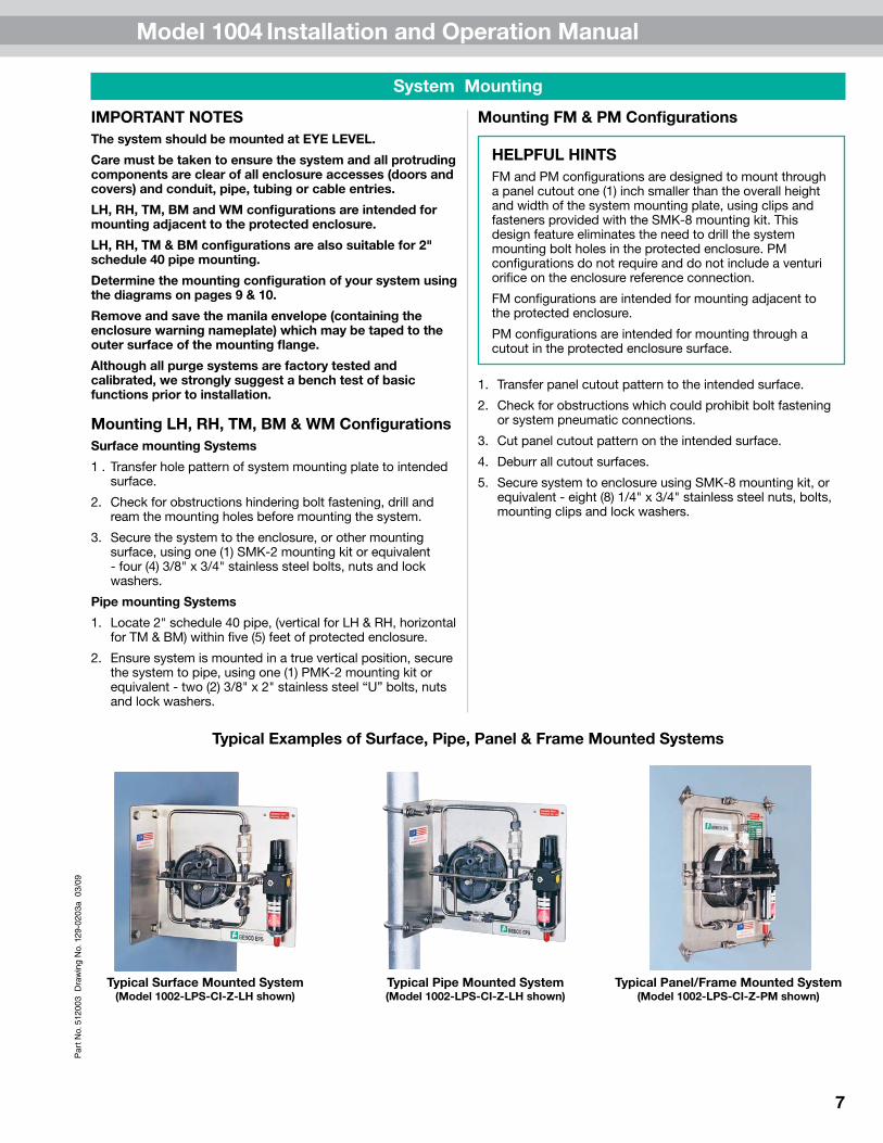
Typical Examples of Surface, Pipe, Panel & Frame Mounted Systems
System Mounting
Typical Surface Mounted System(Model 1002-LPS-CI-Z-LH shown)
Typical Pipe Mounted System(Model 1002-LPS-CI-Z-LH shown)
Typical Panel/Frame Mounted System(Model 1002-LPS-CI-Z-PM shown)

Model 1004 Installation and Operation Manual
8
Par
t No.
512
003
Dra
win
g N
o. 1
29-0
203a
03/
09
Hardware Mounting
Required Enclosure Protection VentAllconfigurationsmustbemountedinatrueverticalposition.
Theventmustbelocatedtoprovideaccessforroutinetestingofthevent’sflapperassembly.Aminimum8"clearanceisrequiredbelowtheventopening.
1. Determinethevent’smountingconfiguration,i.e.,-00verticalmountor-90sidemount.Seephotosbelow.
2.Determineventlocationandlayoutventmountingholeontheprotectedenclosure(asdeterminedonpage6,“GettingStarted”).
3. Usinga1.875"holesawor1.50"conduitpunch,drillanddeburrtheenclosureprotectionventmountinghole.
4. Removethehubmountingnutfromtheventhubandplacethehub,withO-ringintact,throughthemountinghole.TheO-ringmustbeontheoutsideoftheprotectedenclosure.
5. Reinstallthehubmountingnuttothemountinghubfrominsidetheprotectedenclosureandtighten.
Warning Nameplate(s)AnEWN(EnclosureWarningNameplate)mustbelocatedinaprominentpositiononornearallenclosureaccesses(doorsandcovers).
One(1)EWNisprovidedwitheachsystem,locatedinthemanilaenvelopetapedtothemountingflangeofthesystem.AdditionalEWNsareavailablefromPepperl+Fuchs.
AllEWNsprovidelabeledspacesallowingthecustomertomarktheprotectedenclosurewith:1)aTCode(temperatureidentificationnumber),2)Class,GroupandDivisionofsurroundingarea,and3)NFPApressurizationTypeX,YorZ,asmayberequiredbyplantandlocalcodesandisrequiredbyNFPA496.
AnETW(EnclosureTemperatureWarningnameplate)mustbelocatedinaprominentpositiononornearallenclosureaccesses(doorsandcovers)whenthetemperatureofaninternalcomponentexceeds80percentoftheignitiontemperatureoftheflammablevapor,gasordustinvolved.
TheETWwarnstheoperatortodeenergizeallequipmentforaspecifiedlengthoftime,allowingtheprotectedequipmenttocoolbeforeopeningtheprotectedenclosure.Thelengthoftimerequiredisdeterminedbythecustomerandcanbefactoryorfieldengraved.
AllEWNsandETWsarefurnishedwithanadhesiveback,butshouldalsoberivetedorscrewedtotheprotectedenclosure.
Enclosure Temperature Warning Nameplate
Enclosure Warning Nameplate - Class I
EPV - 4 - SA - 00Vertical Mount
EPV - 4 - SA - 90Side Mount
Model 1004 Installation and Operation Manual
9
Par
t No.
512
003
Dra
win
g N
o. 1
29-0
203a
03/
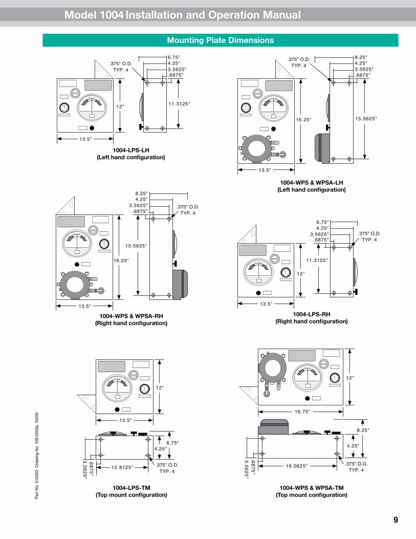
09Mounting Plate Dimensions
4.25"
8.25"
16.0625"
.68
75
"
.375" O.D.TYP. 4
3.5
62
5"
16.75"
12"
1004-LPS-LH(Left hand configuration)
1004-WPS & WPSA-LH(Left hand configuration)
1004-WPS & WPSA-RH(Right hand configuration)
1004-LPS-RH(Right hand configuration)
1004-LPS-TM(Top mount configuration)
1004-WPS & WPSA-TM(Top mount configuration)
4.25"6.75"
.6875"3.5625"
11.3125"
.375" O.D.TYP. 4
12"
13.5"
16.25"
13.5"
4.25"8.25"
.6875"3.5625"
15.5625"
.375" O.D.TYP. 4
4.25"8.25"
.6875"3.5625"
15.5625"
.375" O.D.TYP. 4
16.25"
13.5"
4.25"6.75"
.6875"3.5625"
11.3125"
.375" O.D.TYP. 4
12"
13.5"
12"
13.5"
6.75"
12.8125"
.68
75
"3
.56
25
"
4.25"
.375" O.D.TYP. 4

Model 1004 Installation and Operation Manual
10
Par
t No.
512
003
Dra
win
g N
o. 1
29-0
203a
03/
09
Mounting Plate Dimensions (continued)
1004-WPS & WPSA-WM(Wall mount configuration)
1004-LPS-BM(Bottom mount configuration)1004-WPS & WPSA-BM
(Bottom mount configuration)
6.75"
12.8125"
.68
75
"3
.56
25
"
4.25"
.375" O.D.TYP. 4
12"
13.5"
16.25"
13.5"
14.25"
6"
9.25"
18.25"
Panel Cutout14.5"
Panel Cutout17.25"
15.5"
.25" O.D.TYP. 8
5" 3.25"
1004-WPS & WPSA-FM(Frame mount configuration)
Panel Cutout14.5"
14"
15.5"
Panel Cutout13"
.25" O.D.TYP. 8
5" 1.75"
1004-LPS-FM & 1004-LPS-PM(Frame & panel mount configuration)
16.75"
12"
4.25"
8.25"
16.0625"
.68
75
"
.375" O.D.TYP. 4
3.5
62
5"
1004-LPS-WM(Wall mount configuration)
11.5"
2" 1"
.375" O.D.TYP. 4
6"
10"
7.75"
12"
13.5"
TYPICAL -WMMOUNTING FLANGE

Model 1004 Installation and Operation Manual
11
Par
t No.
512
003
Dra
win
g N
o. 1
29-0
203a
03/
09Pneumatic Tubing Requirements
Protective Gas Supply RequirementsTheprotectivegassupplytotheprotectionsystemmustbeaclean,instrumentqualitycompressedairornitrogenandmustcontainnomorethantraceamountsofflammablegas,vaporordust.
Theprotectivegassupplycompressorintakemustoriginateinanonhazardouslocation.Suctionductpassingthroughahazardouslocationandtheprotectionsystemtubingandpipingmustbefabricatedfromnoncombustiblematerialssuitableforprevailinghazardsandenvironmentalconditions.
Theprotectivegassupplymustoriginatefromadedicatedinstrumentqualitycompressedairheader(1/2"pipeorlarger),nofartherthantwenty(20)feetfromtheprotectionsystem.LocalcompressorsandgascylindersshouldnotbeusedbeforeconsultingwithPepperl+Fuchs.
Theprotectivegassupplytotheprotectionsystemmustberegulatedfrom120psimaximumto80psiminimum.
Pneumatic Connection RequirementsALLFITTINGSMAYBECUSTOMERORFACTORYFURNISHED
1. Forsystemsupply,one(1)SC-81/2"malestraightconnectororone(1)NC-81/2"maleelbowconnectororequivalentfittingpersystem.
One(1)similarfittingwhichwillconnecttheinertgassupplytubingtotheinertgassupplyheaderconnectionpointandone(1)lotof1/2"O.D.,.035"wallthickness,weldedorseamlessstainlesssteeltubing.
2. Forenclosuresupply,one(1)EFC-81/2"flushconnector,orone(1)EBC-81/2"feed-throughconnectororequivalentfittingpersystem.
3.Forenclosurereference,one(1)modelEFC-41/4"flushconnector,orone(1)EBC-41/4"feed-throughconnectororequivalentfittingpersystem.
4.One(1)lotof1/4"O.D.,.035"wallthickness,weldedorseamlessstainlesssteeltubing.
5.Formultipleenclosureconnections,two(2)EPC-141.50"pipemountinghubsorequivalentand1.50"150#ratedpipecouplings&unionsperinterconnection.
One(1)lot150#rating1.50"galvanizedoraluminumpipeandfittings,fullyreamedandunrestricted.
PM Pneumatic Connection RequirementsInadditiontoitemnumbers1,4and5above,thefollowingfittingsarerequiredforallPMconfigurations.
1. ForsystemsupplyonPMconfigurations,one(1)additionalEBC-8orequivalent1/2"throughbulkheadfittingpersystemisrequired.
2. Foratmosphericreference,one(1)PRB-4orequivalent1/4"femalebulkheadfittingandstainlesssteelsinteredelementisrequired
SYSTEM SUPPLY FITTINGSSC-8 NC-8
ENCLOSURE SUPPLY & REFERENCE FITTINGSEBC-4 & EBC-8EFC-4 & EFC-8
EPC-14
SYSTEM ATMOSPHERIC REFERENCE FITTING
PRB-4
MULTIPLE ENCLOSURE CONNECTION FITTING

Model 1004 Installation and Operation Manual
12
Par
t No.
512
003
Dra
win
g N
o. 1
29-0
203a
03/
09
HELPFUL HINTSAllworkmustbeperformedbytechniciansqualifiedinpneumatictubingandelectricalconduitinstallation.
Pepperl+Fuchsrecommendstheuseof.035"wallthickness,weldedorseamlessstainlesssteeltubing.
Ifflexibletubingisused,itmustbeinstalledinamannerthatprotectsitfromdamageandcorrosion.
Tubing Installation
Tubing LH, RH, TM, BM, WM & FM ConfigurationsSystem supply connections
1. Selectorinstallaprotectivegassupplyheadertap,fittedwiththepropertubesizefittingandlocatedwithintwenty(20)feetoftheenclosureprotectionsystem.
2. Ifaservicevalveisplacedbetweentheprotectivegassupplyheaderandtheenclosureprotectionsystem,itmustbeinstalledincloseproximityoftheprotectedenclosureandbelabeledinaccordancewithNFPA496.
3. Selecttheappropriatefittingsrequiredtoconnecttheprotectivegassupplytotheprotectionsystemregulatorasdeterminedonpage11,“PneumaticConnectionRequirements.”
4. Determineappropriatetubingroutefromtheprotectivegassupplyheadertotheprotectionsystemregulator.
5. Bendtubingusingindustrialgradebenders,checktubingfittoensureproperseatingbetweenthetubingandfittings.Fullyreamalltubingends.
6. Installtubingandtightenallfittingstofittingmanufacturer’sspecifications.Securetubingtoappropriatestructuralsupportsasrequired.
Enclosure supply & reference connections
1.Chooselocationfortheenclosuresupplyconnection(s)basedontherequirementsonpage6,“GettingStarted.”
2. Placetheenclosurereferenceconnectionfittingdirectlybehindtheenclosureprotectionsystemandatleastonefootawayfromtheenclosuresupplyandenclosureprotectionventconnections,wheneverpossible.Forsystemsprotectingmultipleenclosuresinseries,theenclosurereferenceconnectionfittingmustbeplacedonthelastenclosureintheseries.Seepage6,“GettingStarted.”
3. Drillanddeburrenclosuresupplyandreferencefittingholesontheprotectedenclosure.Mountthefittings.
4. Determineappropriateroutefortheenclosuresupplyandreferencetubing.
5. Bendtubingusingindustrialgradebenders,checktubingfittoensureproperseatingbetweenthetubingandfittings.Fullyreamalltubingends.
6. Installtubingandtightenallfittingstofittingmanufacturer’sspecifications.Securetubingtoappropriatestructuralsupportsasrequired.
Tubing PM ConfigurationsEnclosure bulkhead fittings
1. Selectthefittingsrequiredtoinstallthesystemsupply,systemsupplybulkheadFittingandatmosphericreferencebulkheadfitting.Seepage11,“PneumaticTubingRequirements.”
2.Chooselocationforthesystemsupplybulkheadfitting.Thisfittingallowstheprotectivegassupplytopassthroughthewallofaprotectedenclosuretotheprotectionsystem’sregulatorsupplyinletconnection.
3. Chooselocationfortheatmosphericreferencebulkheadfitting.Thisfittingallowstheenclosurepressuregaugetoreferenceatmosphericpressure.
4. Drillanddeburrsystemsupplyandreferencebulkheadfittingholesintheprotectedenclosure.Mountthefittings.
System supply & reference connections
1. Selectorinstallaprotectivegassupplyheadertap,fittedwiththepropertubesizefittingandlocatedwithintwenty(20)feetoftheenclosureprotectionsystem.
2. Ifaservicevalveisplacedbetweentheprotectivegassupplyheaderandtheprotectionsystem,itmustbeincloseproximityoftheprotectedenclosureandlabeledinaccordancewiththeNFPA496.
3. Determineappropriatetubingroutefromtheprotectivegassupplyheadertothesystemsupplybulkheadfitting.
4. Determineappropriatetubingroutefromthesystemsupplybulkheadfittingtotheprotectionsystemregulator.
5. Determineappropriatetubingroutefromtheatmosphericreferencebulkheadfittingtotheenclosurepressuregauge’sreferenceinletconnection.
6. Bendtubingusingindustrialgradebenders,checktubingfittoensureproperseatingbetweenthetubingandfittings.Fullyreamalltubingends.
7. Installtubingandtightenallfittingstofittingmanufacturer’sspecifications.Securetubingasrequired.

Model 1004 Installation and Operation Manual
13
Par
t No.
512
003
Dra
win
g N
o. 1
29-0
203a
03/
09Tubing Connection Diagrams
LH, RH, TM, BM, WM & FM Configuration Connection Points & Pneumatic Diagram
PM Configuration Connection Points & Pneumatic Diagram
HELPFUL HINTPneumaticconnectionsarebolded.
RapidExchange
controlvalve
Regulator
System supplyinlet
Enclosure supply outlet
Enclosurepressuregauge
Enclosurereference
inlet
Venturiorifice
Enclosurepressurecontrolvalve
Mountingplate
LPS Style
Protectedenclosure
WPS & WPSA Style
Inlet
Enclosurepressuregauge
OptionalEXPpressureswitch
Sinteredvent
Sinteredvent
Regulator
Venturiorifice
Systemsupply
Reference Enclosurereferencebulkheadfitting
Enclosuresupplybulkheadfitting
Supply
Requiredenclosureprotectionvent
RapidExchange
pressuregaugeRapidExchange
controlvalve
Enclosurepressurecontrolvalve
Enclosurepressuregauge
Atmosphericreference
inlet
Enclosurepressure
controlvalve
Mountingplate
Enclosureprotectionvent
Protectedenclosure
RapidExchange
controlvalve
Regulator
System supply inlet
SystemSupply
InletSystemsupply
bulkhead
Atmosphericreferencebulkhead
Enclosure Supply Outlets
Enclosurepressuregauge
Regulator
RapidExchange
pressuregauge
Sinteredvent
RapidExchange
controlvalve
Enclosurepressurecontrolvalve

Model 1004 Installation and Operation Manual
14
Par
t No.
512
003
Dra
win
g N
o. 1
29-0
203a
03/
09
Electrical Supply Requirements
General Wiring RequirementsWARNING!This device contains electrical parts that can cause shock or injury.
Allelectricalconnections,conduitandfittingsontheprotectedenclosuremustbesuitableforthehazardouslocationinwhichtheyareinstalled.Inaddition,allconduitandwiremustbeinstalledinaccordancewithNECasrequiredandallrelevantplantandlocalcodes.
Note:Donotusesealsonconduitusedasaprotected“wireway”tosupplyprotectivegastoadjacentprotectedenclosures.Thesameconduitcanbeutilizedforbothelectricalandpneumaticservicetoanadjacentprotectedenclosure(s),providedtheconduitisoversizedtoallowaminimumfreeclearanceequaltoorlargerthanthepipesizerequiredbetweenmultipleenclosuresasstatedonpage6,“GettingStarted.”
Enclosure Power RequirementsTheprotectedenclosure(s)electricalpowersourcemustoriginatefromacircuitbreakerorfuseddisconnectsuitableforthehazardouslocationinwhichitisinstalled.Theswitchmustbelocatedwithinfifty(50)feetoftheprotectedenclosure(s)andtheprotectionsystemandbeproperlymarked.
Alarm Signal RequirementsForTypeYandZpurgesystems,audiblealarmsorvisualindicatorsmustbeusedtonotifyoperatorsthatpressureinsidetheenclosureisbelowtheNFPAminimum
Alarmsareconnecteddirectlytotheenclosureandmonitorthedifferentialairpressurebetweentheenclosureandtheenvironmentoutsideit.Thesealarmsareactivatedbythereductioninfloworpressurewithintheprotectiveenclosureandhaveadirectconnectiontotheenclosure,eliminatingtheneedforanalarmontheprotectivegassupply.
• Thealarmmustbelocatedwheretheoperatorcanseeiteasily
• Thealarmmusttakeitsmeasurementfromtheenclosureonly
• Alarmslocatedinthehazardousareamustberatedforthearea
• Valvescannotbeconnectedbetweenthealarmandtheenclosure
IMPORTANT NOTE: NFPA 496 requires the use of an alarm or an indicator to detect the loss of safe enclosure pressure. In addition, the NFPA 496 requires that if an indicator alone is utilized, a protective gas supply alarm must also be installed between the last valve in the protective gas supply and the protected enclosure. Therefore, the protective gas supply to all LPS Style systems must be equipped with the above mentioned protective gas supply alarm. Exception: systems utilizing either an EPSK or GPSK enclosure pressure loss alarm switch accessory will satisfy the above mentioned NFPA requirement.
Typical Enclosure Wiring MethodsProtectedenclosuresshouldbewiredsimilartoexplosionproofenclosures,inaccordancewithArticle500oftheNationalElectricCode-NFPA70.
Singleconductorwiringshouldbeplacedinrigidmetalconduit,seal-flexconduitorothermediumsapprovedforuseinthehazardouslocationsurroundingtheprotectedenclosure.Additionally,NFPA496requirestheuseofapprovedsealsonallpressurizedenclosureconduitwiringentries,inaccordancewithNFPA70.Furthermore,theuseofanapprovedsealissimplythemostpracticalwaytopreventexcessiveleakagethroughconduitconnections.
However,whileexplosionproofenclosuresrequireconduitsealsonallcableentries,inaccordancewithNFPA70.Othermethodsofsealedcableentriesthataresuitableforhazardouslocationscanbeused,suchascompressionglands.
Inconclusion,therearetwoprimarygoals.First,theinstallershouldensurethatallassociatedwiringandcableisprotectedbypressurizationorothermeans,suchasexplosionproofconduitorintrinsicsafetybarriers.Secondly,theinstallershouldensurethatallassociatedconduitandwirewaysaresealedtoconserveprotectivegas,unlesstheyareusedtosupplyprotectivegastootherenclosuresordevices.
Typical Enclosure Wiring Connections
Adjacentpressurized
device
Explosionproofdevice
Seal
Intrinsicallysafeorfiberopticdevice
Independentlypressurized
device
Intrinsicallysafeorfiberopticdevice
Seal
Conduit
Conduit
Conduit
Glandfitting
Cable
Seal
Pressurizedraceway
Protectedenclosureordevice

Model 1004 Installation and Operation Manual
15
Par
t No.
512
003
Dra
win
g N
o. 1
29-0
203a
03/
09Conduit Installation
Electrical Conduit1.Choosethelocationfortheenclosure’selectricalconduit
connection(s)basedontherequirementsonpage14,“ElectricalSupplyRequirements.”
2. Drillanddeburrenclosureconduitfittingholesintheprotectedenclosure.Mountthefittings.
3. Determineappropriateroutefortheenclosureelectricalandpoweralarmsignalconduit.
4. Measure,cutandthreadconduit,checkconduitfittoinsureproperseating.Fullyreamallconduit.
5. Installconduitandtightenallfittingstofittingmanufacturersspecifications.Secureconduittoappropriatestructuralsupportsasrequired.
6. Sealallconduitwithanapprovedcompoundpriortooperationoftheprotectionsystem.
WPS & WPSA Style ConduitWPSandWPSAstylesystemsprovideelectricalcontactsforaudibleorvisualalarmdevicesthatsignalalossofprotectedenclosurepressure.WPSandWPSAstylesystemsarecalibratedtoalarmat0.15"forClassIapplications.Theswitchesaresuitableforhazardous(classified)outdoorlocations.Wiringmustbeinstalledwithasealandconduitfittingssuitableforthearea.Alarmcircuitpowermaybederivedfromtheprotectedenclosurepowersourceoranintrinsicallysafealarmsignalsource.Allassociatedalarmdevicesmustbeprotectedbysuitablemeans(explosionproof,purgedorintrinsicallysafe).
WPS & WPSA Style Conduit Connection PartsFittingKitsCanBeFactoryFurnished
1. ForWPSandWPSAstyleEXPpressurelossalarmswitchconnectedtoanenclosuremountedalarm,one(1)LCK(Lfittingconduitkit)orequivalentconduitelbow,couplingandsealfittings.
2. ForWPSandWPSAstyleEXPpressurelossalarmswitchconnectedtoaremotemountedalarm,one(1)TCK(Tfittingconduitkit)orequivalentconduittee,couplingandsealfittings.
3. One(1)lot150#rating1/2”galvanizedoraluminumpipe.
HELPFUL HINTItmaybeimpracticaltopourallelectricalconduitsealspriortoinstallationinthefield.However,allconduitconnectionsmustbesealedforpropertestingandoperationoftheenclosureprotectionsystem.Therefore,theuseoftemporarysealssuchasductsealormaskingtapeforbenchorshoptesting,priortofinalfieldinstallationmaybeused.
LCK “L” Fitting Conduit Kit
TCK “T” Fitting Conduit Kit
WPS Style EXP Pressure SwitchWith Cover Removed
Switchbody
Setpointcalibration
screw
Groundingscrew
1/2"conduitport
Electricalswitch
contacts
Lowportsintered
vent
Highporttubefitting
WPSA Style EXP Pressure SwitchWith Cover Removed
Switchbody
Setpointcalibration
screw
Groundingscrew
1/2"conduitport
Lowportsintered
vent
120VACpower&electricalswitch
contacts
Highporttubefitting

Model 1004 Installation and Operation Manual
16
Par
t No.
512
003
Dra
win
g N
o. 1
29-0
203a
03/
09
Set-up Procedure
Class I Purging Set-up1.ClosetheenclosurepressureandRapidExchangecontrol
valvesfullybyturningclockwise(CW).
2.ConnecttheinertgassupplytothesystemsupplyinletandsettheRapidExchangepressuregaugeto80psi.
3. Temporarilyconnecta0-10inchwatercolumnpressuregaugeormanometertotheprotectedenclosure.
4.Checkoperationofenclosureprotectionventasdetailedabove.See"HelpfulHint."
5.Sealenclosure(s)andadjustenclosurepressurecontrolvalvebyopeningslowlycounterclockwise(CCW)toseta“safe”pressureontheenclosurepressuregauge.
NOTE:Ifpressuresettingisdifficulttostabilizeorset,seepage18,“TroubleshootingProcedures.”
6.OpenRapidExchangecontrolvalvefullybyturning90°CCWandquicklyensuretheenclosureprotectionventopens.Note:Theenclosurepressuregaugeshouldmovequicklyoffscaletotheright,thisisnormalforallRapidExchangepurgingsystems.
7. Readjusttheregulatorto80psiminimum,whileinducingRapidExchange,untilthetestgaugereadsapproximately2inchesofpressureanddoesnotfluctuate.(insufficientenclosurepressurewillcausetheenclosureprotectionventto"shuttle")DONOTexceed10inchesofpressurewithintheprotectedenclosure.
8. Installandtightenallboltsonthepressurelossalarmswitch(ifutilized).Ensuretheconduitissealedwithapprovedcompounds.Energizepowertoswitchandalarmsystem(ifutilized)andtestthefunctionofthealarmsystem.
9.Ceasetestingandremovetestequipment.
Pepperl+FuchsRapidExchangepurgingsystemsprovideapre-calibratedandcertifiedvolumeexchangerate.WiththeRapidExchangepressuregaugesetat80psiminimum,themodel1004willaccomplishtherequiredvolumeexchangesatarateofONEMINUTEPER7.5CUBICFEETofenclosurevolume.
NOTE:Thevolumeexchangerateisbasedonafour(4)enclosurevolumeexchange.Multiplytherequiredexchangetimeby2.5forapplicationsrequiringaten(10)volumeexchange(motors).
Regardlessofenclosurevolumeorsystemflowrate,itisrequiredthatoperatorswithholdpowertotheenclosurewhileinducingtheClassIenclosurevolumeexchange,foratleastfive(5)minutes.Normalexchangetimesshouldbedoublediflargeobstructionsblockinertgasflow.
Thestart-upinstructionnameplateexchangetimeslotwillfeaturethestandardfactorforthissystem"ONEMINUTEPER7.5CUBICFEET,"buttheunitmayfeatureasetofdirectfactornameplateswithself-adhesivebackingsuchas“TENMINUTES,”forapplicationtothestart-upinstructions,dependentonhowthesystemwasspecifiedandpurchased.Fieldmodificationofthisnameplate,toshowadirectfactor,isacceptableasnotedaboveifthemethodusedtomarkthenameplatedoesnotdefacetheinstructionslisted.Materialsusedforthemarkingmustbeindelibleandwithstandprevailingenvironmentalconditions.
IMPORTANT NOTE: Operators must secure wrist or stop watch to manually time exchange cycle for all applications.
HELPFUL HINTSTheterm“safe”pressureforpurposesofthismanualisdefinedasaminimum.25inchofwatercolumnpressure.
Regulatormaybeinthelockedpositionuponarrival.Toadjustregulator,pullhandletooutwardposition.
Totestthevent’soperation,gentlyprodtheventflapperopenwithasoft-pointedobject,(example:eraserendofapencil)ensuringthattheventvalveworksfreely.Onverticallyconfiguredvents,thiscanbeaccomplishedfromwithintheprotectedenclosure.Sidemounted-90configuredventscanbetestedbyremovingtheconduitplugatthebottomofthemountingtee.Multipleoperationsrequireonlyonetestperdayifenclosureisnotopenedorleftunattended.
Model 1004 Installation and Operation Manual
17
Par
t No.
512
003
Dra
win
g N
o. 1
29-0
203a
03/
09Operating Sequence
WARNING! Do not exceed "safe" pressure with theenclosure pressure control valve. Operators must
follow step-by-step sequence of the start-up instructions nameplate on the protection system.
Class I Purging OperationWiththeinertgassupplyconnected,enclosurepower
deenergizedandalarmsystemenergized(ifutilized).
1.Carefullyreadstart-upinstructionnameplateonsystem.
2.Checkoperationoftheenclosureprotectionvent(modelEPV-4),openingitmanuallyseveraltimes.Seepage16,“HelpfulHint.”
3.Sealprotectedenclosure(s).
4.Openenclosurepressurecontrolvalve,byturningCCW,tosetenclosurepressuregaugeat“safe”pressure,thepressurelossalarmswitchshouldthenactivatetosilencethealarmsystem(ifutilized).
5.Ensuretheprotectionsystemenclosurepressuregaugemaintainsa“safe”pressureforone(1)minute.
6.OpenRapidExchangecontrolvalvefullybyturning90°CCWandquicklyensuretheenclosureprotectionventopens.Note:Theenclosurepressuregaugeshouldmovequicklyoffscaletotheright,thisisnormalforallRapidExchangepurgingsystems.
7. Standbyfortheexchangetimeasspecifiedonthestart-upinstructionnameplate(fiveminutesminimum),thenclosetheRapidExchangecontrolvalvefully.
8. Waitfortheenclosurepressuregaugetoreturntoa"safe"pressureandenergizetheprotectedenclosure(s)powerviathelocaldisconnectswitch.
9.Ensuretheenclosurepressureindicatormaintainsa“safe”pressurebeforeleavingsystemunattended.
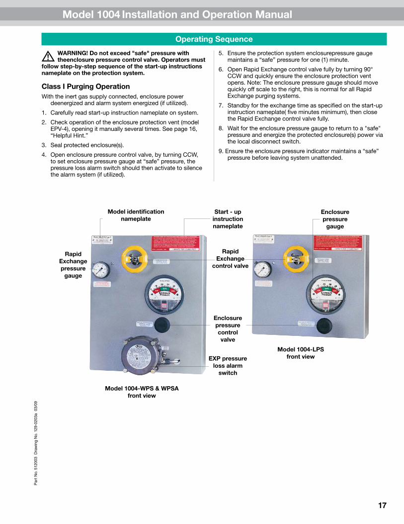
Model identification nameplate
Model 1004-LPS front view
Model 1004-WPS & WPSA front view
Enclosure pressure control valve
EXP pressure loss alarm
switch
Enclosure pressure
gauge
Rapid Exchange
pressure gauge
Start - up instruction nameplate
Rapid Exchange
control valve

Model 1004 Installation and Operation Manual
18
Par
t No.
512
003
Dra
win
g N
o. 1
29-0
203a
03/
09
Troubleshooting Procedures
Problem or Fault Possible Causes Corrective Action
Enclosurepressurecontrolvalvewillnotholda"safe".25inchpressure.
Leakagearoundgasketing,covers,seams,pipingandtubingconnections,conduitconnectionsandelectricalconduitsealsoftheenclosure.
Tightenenclosurelatches:Wheretighteningisnotfeasible,andgasketingmaterialsarenotpractical,holesorgapscanbeclosedwithsiliconesealantappliedfrominsidetheprotectedenclosure.
Enclosurepressuregaugereadingisdifficulttostabilize.
Insufficientenclosureleakageoropeningoftheventuriorificeiscrimpedtosmall.
Removetheorifice,cutoffthecrimpedendandreamthetube,thenrecrimpandreinstallthetubetonoteeffect.Astubeisshortened,reamed,andrecrimped,sensitivitydecreases,allowingeasieradjustmentofsetpointontheenclosurepressuregauge.
Enclosurepressurelossalarmswitchdoesnotappeartobeoperating.
Pressureswitchisoutofcalibration.
Pressureswitchhasnotbeenenergized(WPSAstylesystemsonly).
Calibratebyslowlyadjustingcounterclockwisetodecreasethesetpoint,andclockwisetoraisethesetpoint.(Donotattempttocalibratetheswitchuntilalleffortstomaketheswitchrespondproperlyhavefailed).
VerifythepowersupplyhasbeenappliedtopowercontactsofWPSAstylesystem.
Problemspersists,orifthesystemdoesnotappeartobeoperatingproperly.
Persistingproblems. ContactPepper+Fuchsapplications/customerservicedepartmentat330-486-0002
Thissectioncoversthemostcommonproblemsdocumentedwiththissystem.Anyproblemsnotcoveredinthissectionshouldbeaddresseddirectlytoourfactory.Pleaseaddressallserviceneedsto:
Pepperl+Fuchs, Inc. Customer Service Department

Model 1004 Installation and Operation Manual
19
Par
t No.
512
003
Dra
win
g N
o. 1
29-0
203a
03/
09
PEPPERL+FUCHS STANDARD 24-MONTH WARRANTY1. LimitedWarranty.Pepperl+Fuchs,Inc.(“P+F")warrantsPurgeUnitsandcomponentsforPurgeUnitsmanufacturedbyP+F
(“Product"or“Products")tobefreefromdefectsinmaterialandworkmanshipunderNormalUseforaperiodoftwenty-four(24)monthsfromthedateofshipmentofsuchProductsfromP+F’swarehouseorplaceofmanufacture(orfromP+F’sauthorizedrepresentativeordistributor).OnlytheoriginalpurchaserofsuchProducts(the“Customer")shallbeentitledtothebenefitoftheforegoingLimitedWarranty.Norepresentative,agentorsalesmanofP+FisauthorizedtogiveorprovideanywarrantyormakeanyrepresentationcontrarytoorinadditiontotheforegoingLimitedWarranty.
2. InspectionandClaims.CustomermustinspectandtestallProductsuponreceipt.AllclaimsundertheLimitedWarrantyprovidedhereinmustbemadewithinthirty(30)daysofthediscoveryofthedefect.CustomermustobtainshippinginstructionsfromP+FpriortoreturninganyProduct,whichProductmustbereturnedatCustomer’sexpenseinaccordancewithP+F’sinstructions.
3. LimitationsandExclusions.“NormalUse"shallmeanuseandoperationwithinratedcapacities,atthecorrectvoltage,andwithanyrequiredmaintenanceasprovidedintheapplicableP+FOperatingManuals.TheLimitedWarrantyprovidedhereindoesnotapplyto(i)anyProductswhichhavebeenalteredormodifiedinanywayordisassembledbytheCustomeroranyoneelse,(ii)anyProductswhichhavebeensubjecttomisuse,negligenceoraccident,orimproperlyinstalled,changed,substitutedorreplaced,(iii)anypartorcomponentnotmanufacturedbyP+F,or(iv)anypartorcomponentthatissubjecttowearorconsumption.ForpartsorcomponentsnotmanufacturedbyP+F,theCustomeroranyotheruserorownershallhaveonlythewarrantyprovidedbythemanufacturerofsuchpartorcomponent.TheLimitedWarrantysetforthhereinisalsosubjecttothefollowing:
(1) TheLimitedWarrantyislimitedtoelectronicandmechanicalperformanceonly,asexpresslydetailedintheproductspecifications,anddoesnotapplytocosmeticappearance;
(2) TheLimitedWarrantyshallnotapplytoanycablesattachedto,orintegratedwith,anyProducts.
(3) TheLimitedWarrantyshallnotapplytoanyProductswhicharestored,orutilized,inharshenvironmentalorelectricalconditionsoutsideP+F’swrittenspecifications.
THELIMITEDWARRANTYSETFORTHHEREINISTHEONLYWARRANTYMADEBYP+FWITHRESPECTTOTHEPRODUCTS.ITISEXPRESSLYAGREEDANDUNDERSTOODTHATP+FMAKESNOWARRANTYOFMERCHANTABILITYORFITNESSFORAPARTICULARPURPOSE.EXCEPTFORTHELIMITEDWARRANTYSETFORTHHEREIN,THEREISNOOTHERWARRANTY,EXPRESS,IMPLIEDORSTATUTORY;ANDTHEREISNOAFFIRMATIONOFFACTORPROMISEBYP+FWITHREFERENCETOTHEPRODUCTS.INNOEVENTSHALLP+FBELIABLEFORACTUALORANTICIPATEDLOSTPROFITSORFORINCIDENTALORCONSEQUENTIALORPUNITIVEDAMAGESORFORDAMAGESRESULTINGFROMBUSINESSINTERRUPTION,ORINJURYORDEATHOFPERSONS,ORINJURYTOPROPERTY.P+F’SLIABILITYONANYCLAIMOFANYKINDARISINGOUTOF,CONNECTEDWITHORRESULTINGFROMTHEDESIGN,MANUFACTURE,SALE,REPAIROROPERATIONOFAPRODUCT,SHALLNOTEXCEEDTHEPRICEALLOCABLETOTHATPRODUCTORTHEPARTTHEREOFWHICHGIVESRISETOTHECLAIM.THEREMEDYSETFORTHINTHISLIMITEDWARRANTYCONSTITUTESTHESOLEANDEXCLUSIVEREMEDYOFTHECUSTOMER.P+FSHALLNOTBELIABLEFORPENALTIESOFANYDESCRIPTION.
4. LimitationofRemedies.IntheeventofP+F’sliability,whetheronthisLimitedWarrantyorbasedoncontract,tort(including,butnotlimitedto,negligenceandstrictliability)orotherwise,Customer’ssoleandexclusiveremedywillbelimitedto,atP+F’soption,therepairorreplacement(f/o/bP+F’splaceofmanufacture)byP+Fofanynon-conformingitemsforwhichclaimismadebyCustomerinaccordancewithparagraph2,ortherepaymentoftheportionofthepurchasepricepaidbyCustomerattributabletothenon-conformingitem.
5. ResponsibilityofCustomer:SafetyandProtectionPrecautions.P+FtakesgreatcaretodesignandbuildreliableanddependableProducts;however,someProductscanfaileventually.Customermusttakeprecautionstodesignitsequipmenttopreventpropertydamageandpersonalinjuryintheunlikelyeventofafailure.ASAMATTEROFPOLICY,P+FDOESNOTRECOMMENDTHEINSTALLATIONOFPRODUCTSASTHESOLEDEVICEFORTHEPROTECTIONOFPERSONNELORPROPERTYAND,THEREFORE,THECUSTOMERSHOULDBUILDINREDUNDANCYORDUALCONTROLUSINGAPPROVEDSAFETYDEVICESFORTHESEAPPLICATIONS.
6. Conflicts.IntheeventthereisanyconflictbetweentheprovisionsofthisLimitedWarrantyandanyprovisionscontainedinanyorders,offers,acceptancesorotherwritingsorstatementsprovidedormadebyCustomertoP+F,theprovisionsofthisLimitedWarrantyshallprevail,andthecontractbetweenP+FandtheCustomershallbedeemedformedonlyupontheprovisionssetforthinthisLimitedWarranty,andanyadditionalorconflictingprovisioninsertedbyCustomershallbeofnoforceoreffect.
Warranty Terms and Conditions

Model 1004 Installation and Operation Manual
20
Par
t No.
512
003
Dra
win
g N
o. 1
29-0
203a
03/
09
Notes

Model 1004 Installation and Operation Manual
21
Par
t No.
512
003
Dra
win
g N
o. 1
29-0
203a
03/
09Notes

Model 1004 Installation and Operation Manual
22
Par
t No.
512
003
Dra
win
g N
o. 1
29-0
203a
03/
09
System Maintenance
Regular MaintenanceDraintheprotectionsystemregulatorfrequentlyandcleansystemwithnonsolventcleaningagentsonly.
Long-Term MaintenanceCalibratetheenclosurepressureindicatorto0inchesbyventingthepurgepressurereferenceportandtheprotectedenclosuretoatmosphereandadjustingthecalibrationscrewinthelowercenterportionoftheindicator’sface.
Fullyopentheenclosurepressurecontrolregulator,toblowoutanydepositsaroundthetipofthevalveandtoensurethattheenclosureprotectionventisoperatingproperly,thencarefullyreadjustsystemaccordingtotheset-upprocedureandoperatingsequenceonpages16and17.Replaceortightenstempackingnutasrequiredtoprohibitstempackingleakage.
Carefullydisassembletheenclosureprotectionventbylooseningthetwobottomhexnutsthatholdtheunittogether.
(DO NOT REMOVE CAP NUTS ON TOP OF VENT BODY)
Carefullycleantheflappervalveandventbodyseatswithwarmsoapandwater,beingcarefulnottoextendtheventvalvebeyonditsnormalopeningpoint,andbeingcarefulnottoexertanystressonthevalvehinge.
Examinetheentireprotectionsystemandtheprotectedenclosure(s),andreplaceanydefectivepartsduringroutineshutdownoftheprotectedenclosure(s).PartsareavailablefromPepperl+Fuchsonimmediatenoticeasrequired.
MAINTENANCE SCHEDULEDate Work performed Performed by

Model 1004 Installation and Operation Manual
23
Par
t No.
512
003
Dra
win
g N
o. 1
29-0
203a
03/
09Systems Identification & Application Information
Date of installation _____________________________________________________
Unit serial #____________________________________________________________
Item ___________________________________________________________________
Customer P.O.# ________________________________________________________
Customer project# _____________________________________________________
Service ________________________________________________________________
Type __________________________________________________________________
Features ______________________________________________________________
Application ____________________________________________________________
Notes: _______________________________________________________________________________________________
_____________________________________________________________________________________
_____________________________________________________________________________________
_____________________________________________________________________________________
_____________________________________________________________________________________
_____________________________________________________________________________________
_____________________________________________________________________________________
_____________________________________________________________________________________
_____________________________________________________________________________________
_____________________________________________________________________________________