Embed Size (px)
Citation preview
234782-1
Installation and Operation Manual
E32D5 (Digital Operation)
30DSERIES
The reproduction or copying of any part of this manual by any means whatsoever is strictly forbidden unless authorized previously in writing by the manufacturer. In line with policy to continually develop and improve its products, Moffat Ltd. reserves the right to change the specifications and design without prior notice.
© Copyright Moffat Ltd. July 2010.
MANUFACTURED BY Moffat Limited Christchurch New Zealand INTERNATIONAL CONTACTS AUSTRALIA
Moffat Pty Limited E.Mail: [email protected] Main Office: (tel) (03) 9518 3888 (fax) (03 9518 3833 Service: (tel): 1800 622 216 Spares: (tel): 1800 337 963 Customer Service: (tel): 1800 335 315 (fax): 1800 350 281 CANADA
Serve Canada Web: www.servecanada.com E.Mail: [email protected] Sales: (tel): 800 551 8795 (Toll Free) Service: (tel): 800 263 1455 (Toll Free) NEW ZEALAND
Moffat Limited Web: www.moffat.co.nz E.Mail: [email protected] Main Office: (tel): 0800 663328 UNITED KINGDOM
Blue Seal Web: www.blue-seal.co.uk E.Mail: [email protected] Sales: (tel): 0121 327 5575 (fax): 0121 327 9711 Spares: (tel): 0121 322 6640 (fax): 0121 327 9201 Service: (tel): 0121 322 6644 (fax): 0121 327 6257 UNITED STATES
Moffat Web: www.moffat.com Sales: (tel): 800 551 8795 (Toll Free) (tel): 336 661 1556 (fax): 336 661 9546 Service: (tel): 800 858 4477 (Toll Free) (tel): 366 661 1556 (fax): 336 661 1660 REST OF WORLD
Moffat Limited Web: www.moffat.co.nz E.Mail: [email protected]
Contents List
E32 Turbofan Convection Oven.
Model Numbers Covered in this Manual
E32D5 - Turbofan Oven - 5 Tray Convection Oven.
Introduction........................................................................................................... 2 Safety Information
Specifications......................................................................................................... 3
Installation............................................................................................................. 4 Installation Requirements Unpacking Location Clearances Stand Mounted Ovens Electrical Connection Water Connection Positioning and Levelling of Oven Initial Start-Up Commissioning Reversing the Oven Door
Operation ............................................................................................................... 8 Operation Guide Oven Control Panel Using the Oven - Manual Mode Cooking in Program Mode Setting the Oven Programs Oven Racks
Operator Accessible Parameters.......................................................................... 13 Setting the Operator Accessible Parameters Table of Operator Accessible Parameters
Cleaning ............................................................................................................... 14 Cleaning Guidelines Oven Cleaning
Fault Finding ........................................................................................................ 17
Electrical Schematics ........................................................................................... 18
Replacement Parts List ........................................................................................ 19
Introduction
2
Before using your new oven, please read this instruction manual carefully, pay particular attention to any information labelled ‘WARNING’, ‘CAUTION’, ‘IMPORTANT’ or ‘NOTE’ in this manual.
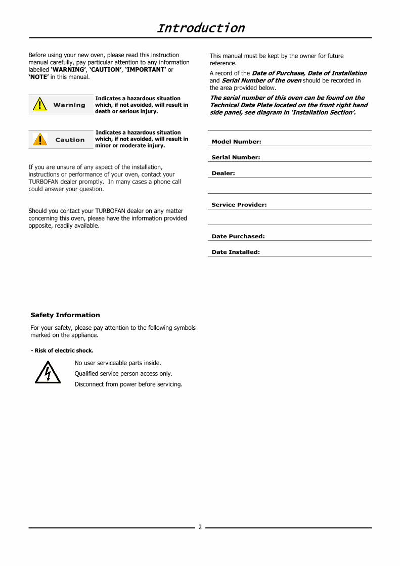
Indicates a hazardous situation which, if not avoided, will result in death or serious injury.
Indicates a hazardous situation which, if not avoided, will result in minor or moderate injury.
If you are unsure of any aspect of the installation, instructions or performance of your oven, contact your TURBOFAN dealer promptly. In many cases a phone call could answer your question. Should you contact your TURBOFAN dealer on any matter concerning this oven, please have the information provided opposite, readily available.
Caution
Warning
Model Number:
Serial Number:
Dealer:
Service Provider:
Date Installed:
Date Purchased:
This manual must be kept by the owner for future reference.
A record of the Date of Purchase, Date of Installation and Serial Number of the oven should be recorded in the area provided below.
The serial number of this oven can be found on the Technical Data Plate located on the front right hand side panel, see diagram in ‘Installation Section’.
Safety Information
For your safety, please pay attention to the following symbols marked on the appliance. - Risk of electric shock.
No user serviceable parts inside.
Qualified service person access only.
Disconnect from power before servicing.
Specifications
3
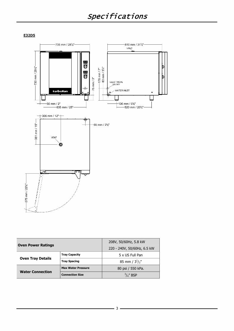
E32D5
Oven Power Ratings 208V, 50/60Hz, 5.8 kW
220 - 240V, 50/60Hz, 6.5 kW
Oven Tray Details Tray Capacity 5 x US Full Pan
Tray Spacing 85 mm / 31/3”
Water Connection Max Water Pressure 80 psi / 550 kPa.
Connection Size 3/4” BSP
Installation
4
MODEL
SERIAL xxxxxxLOT yywwxxx
CHRISTCHURCH ( NEW ZEALAND )
REGULATIONS AND USED ONLY IN A WELL-VENTILATED SPACE. REFER TO THETHIS APPLIANCE SHALL BE INSTALLED IN ACCORDANCE WITH CURRENT
THIS APPLIANCE MUST BE EARTHED / GROUNDED
MOFFAT LIMITED
INSTRUCTIONS BEFORE INSTALLING AND USING THIS APPLIANCE.
A @ V a.c.
V a.c. Hz kW
CODE
1P+N+E
E22M3USE22M3
12.0 115
110-120 50-60 1.5
Installation Requirements
Unpacking
1. Remove all packaging and transit protection including all protective plastic coating from the exterior stainless steel panels.
2. Check the oven and supplied parts for damage. Report any damage immediately to the carrier and distributor.
3. Check that the following parts have been supplied with your oven:-
4 x Leg Adjustable. Water Connection Elbow. 4. Report any deficiencies to the distributor who supplied
your oven. 5. Securely fit the 4 legs supplied with the oven. 6. Check that the available electrical supply is correct to
that shown on the Technical Data Plate located on the front right hand side panel.
• Refer to ‘Specifications’ section, ‘Oven Specifications Tables’.
Location
1. Position the oven in its approximate working position. 2. The unit should be positioned so that the control panel
and oven shelves are easily reachable for loading and unloading.
Clearances
To ensure correct ventilation for the motor and controls, the following minimum installation clearances are to be adhered to:-
Top 200 mm / 8”. Rear 75 mm / 3”. Left-hand side 75 mm / 3”. Right-hand side 75 mm / 3”.
NOTE: Fixed installations require at least 500 mm -
20” clearance at the right hand side of oven for service access.
Stand Mounted Oven
For ovens that are to be mounted to a stand, the oven feet are used to level the oven on the stand. Refer to the instructions supplied with separately ordered stands for mounting details.
Important:
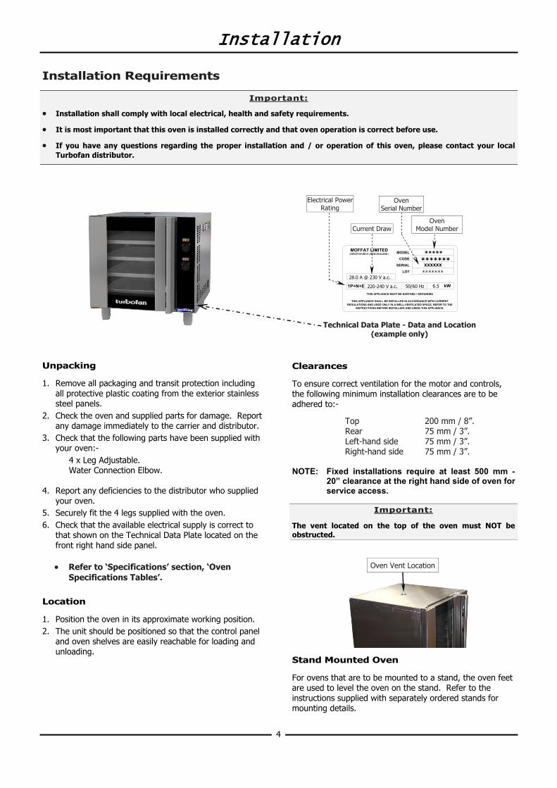
The vent located on the top of the oven must NOT be obstructed.
Important:
• Installation shall comply with local electrical, health and safety requirements.
• It is most important that this oven is installed correctly and that oven operation is correct before use.
• If you have any questions regarding the proper installation and / or operation of this oven, please contact your local Turbofan distributor.
Oven Serial Number
Current Draw Oven
Model Number
Electrical Power Rating
Technical Data Plate - Data and Location (example only)
*******
***** *******
6.5 220-240 V a.c. 50/60 Hz
28.0 A @ 230 V a.c.
Oven Vent Location
Installation
5
Electrical Connection
Each oven should be connected to an adequately protected power supply with an appropriate three wire power cord. An isolation switch must be mounted adjacent to, but not behind the oven and must be readily accessible to the operator. This switch must be clearly marked and readily accessible in case of fire. Check the electricity supply is correct to as shown on the Technical Data Plate on the front right hand corner of the oven side panel. NOTE: All electrical connections must only be carried
out by a suitably qualified person. 1. Remove oven right hand side panel. 2. Bring the supply cable up through the grommet at the
back of oven and through the compression gland on the electrical switchgear panel.
3. Connect the mains supply to the appropriately marked terminals on the terminal block.
Water Connection - Optional (not required for main oven operation)
1. If the manual addition of water into the oven for humidification or steaming effect on baked product is required, the unit’s water connection can be used.
2. A cold water supply should be fitted to the water inlet (¾” BSP hose connection) which is located on the rear of the right hand side of the oven.
3. Alternately, a connection elbow and sealing washer is supplied with this unit for direct connection of a ½” ID hose, and is recommended for easy installation and service.
4. Connect to the water supply.
- Max Inlet Pressure 80psi / 550kPa.
5. Turn ‘On’ the water supply and check for leaks. Positioning and Levelling of Oven
1. Correctly locate the oven into its final operating position and using a spirit level, adjust the oven feet so that the oven is level and at the correct height.
Initial Start-Up
Before using the new oven;
1. For first time use of the oven, operate the oven for about 1 hour at 200°C / 400°F to remove any fumes or odours which may be present.
2. Please refer to the Operation Section of this manual for details on how to correctly operate and shutdown the oven.
This oven must be earthed / grounded.
Warning
Commissioning
Before leaving the new installation; Check the oven functions in accordance with the operating instructions specified in the ‘Operation’ section of this manual.
Ensure that the operator has been instructed in the areas of correct operation and shutdown procedure for the appliance. NOTE: If for some reason it is not possible to get the
appliance to operate correctly, turn off the power supply at the mains supply and contact the supplier of this appliance.
Installation
6
Reversing the Oven Door
NOTE: This operation should only be carried out by a suitably competent person.
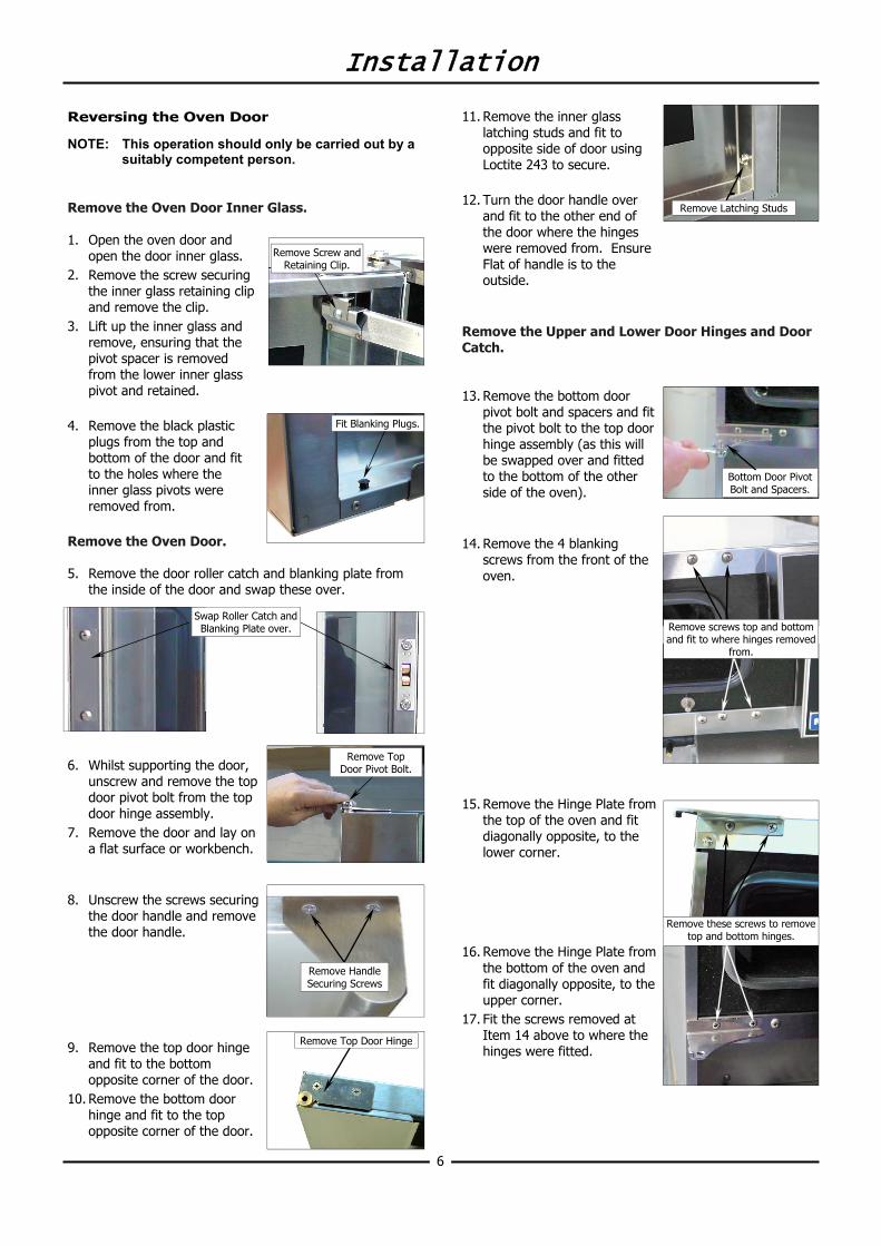
Remove the Oven Door Inner Glass. 1. Open the oven door and
open the door inner glass. 2. Remove the screw securing
the inner glass retaining clip and remove the clip.
3. Lift up the inner glass and remove, ensuring that the pivot spacer is removed from the lower inner glass pivot and retained.
4. Remove the black plastic
plugs from the top and bottom of the door and fit to the holes where the inner glass pivots were removed from.
Remove the Oven Door. 5. Remove the door roller catch and blanking plate from
the inside of the door and swap these over.
6. Whilst supporting the door, unscrew and remove the top door pivot bolt from the top door hinge assembly.
7. Remove the door and lay on a flat surface or workbench.
8. Unscrew the screws securing
the door handle and remove the door handle.
9. Remove the top door hinge
and fit to the bottom opposite corner of the door.
10. Remove the bottom door hinge and fit to the top opposite corner of the door.
Fit Blanking Plugs.
Remove Top Door Pivot Bolt.
Remove Top Door Hinge
Remove Handle Securing Screws
Swap Roller Catch and Blanking Plate over.
11. Remove the inner glass latching studs and fit to opposite side of door using Loctite 243 to secure.
12. Turn the door handle over
and fit to the other end of the door where the hinges were removed from. Ensure Flat of handle is to the outside.
Remove the Upper and Lower Door Hinges and Door Catch. 13. Remove the bottom door
pivot bolt and spacers and fit the pivot bolt to the top door hinge assembly (as this will be swapped over and fitted to the bottom of the other side of the oven).
14. Remove the 4 blanking
screws from the front of the oven.
15. Remove the Hinge Plate from
the top of the oven and fit diagonally opposite, to the lower corner.
16. Remove the Hinge Plate from
the bottom of the oven and fit diagonally opposite, to the upper corner.
17. Fit the screws removed at Item 14 above to where the hinges were fitted.
Remove these screws to remove top and bottom hinges.
Bottom Door Pivot Bolt and Spacers.
Remove screws top and bottom and fit to where hinges removed
from.
Remove Latching Studs
Remove Screw and Retaining Clip.
Installation
7
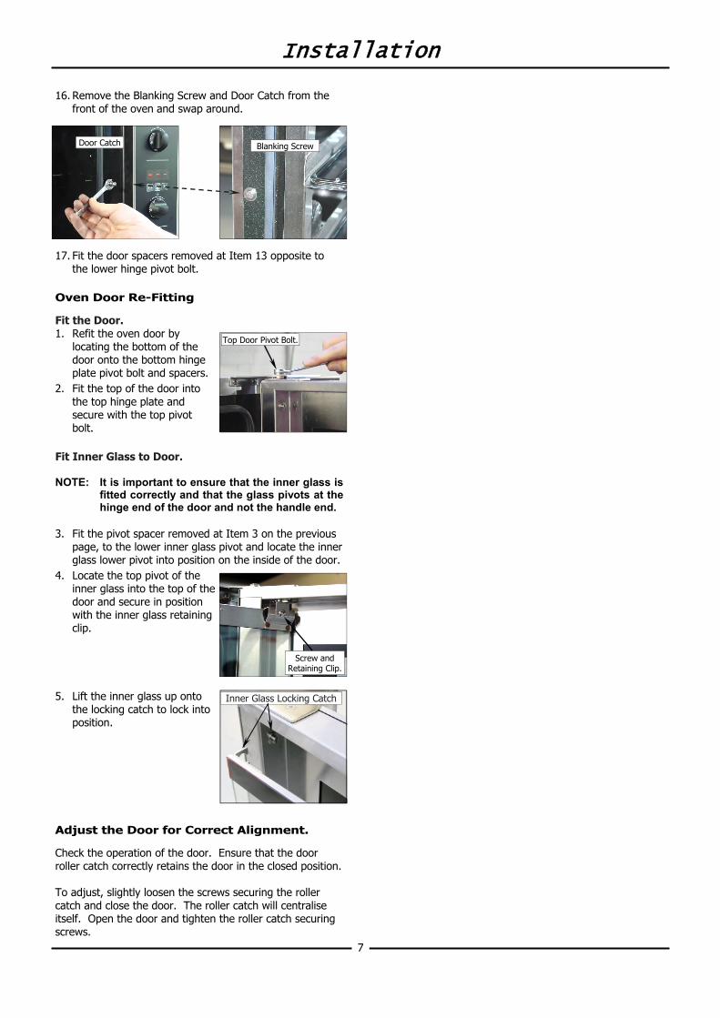
16. Remove the Blanking Screw and Door Catch from the front of the oven and swap around.
17. Fit the door spacers removed at Item 13 opposite to the lower hinge pivot bolt.
Oven Door Re-Fitting
Fit the Door. 1. Refit the oven door by
locating the bottom of the door onto the bottom hinge plate pivot bolt and spacers.
2. Fit the top of the door into the top hinge plate and secure with the top pivot bolt.
Fit Inner Glass to Door. NOTE: It is important to ensure that the inner glass is
fitted correctly and that the glass pivots at the hinge end of the door and not the handle end.
3. Fit the pivot spacer removed at Item 3 on the previous
page, to the lower inner glass pivot and locate the inner glass lower pivot into position on the inside of the door.
4. Locate the top pivot of the inner glass into the top of the door and secure in position with the inner glass retaining clip.
5. Lift the inner glass up onto
the locking catch to lock into position.
Adjust the Door for Correct Alignment.
Check the operation of the door. Ensure that the door roller catch correctly retains the door in the closed position. To adjust, slightly loosen the screws securing the roller catch and close the door. The roller catch will centralise itself. Open the door and tighten the roller catch securing screws.
Screw and Retaining Clip.
Top Door Pivot Bolt.
Blanking Screw Door Catch
Inner Glass Locking Catch
Operation
8
Operation Guide
• Turbofan Ovens have been designed to provide simple operation.
• This oven is intended for use in a commercial kitchen and must only be put to the use for which it was intended, i.e. cooking food product. To use this oven correctly please read the following sections carefully:-
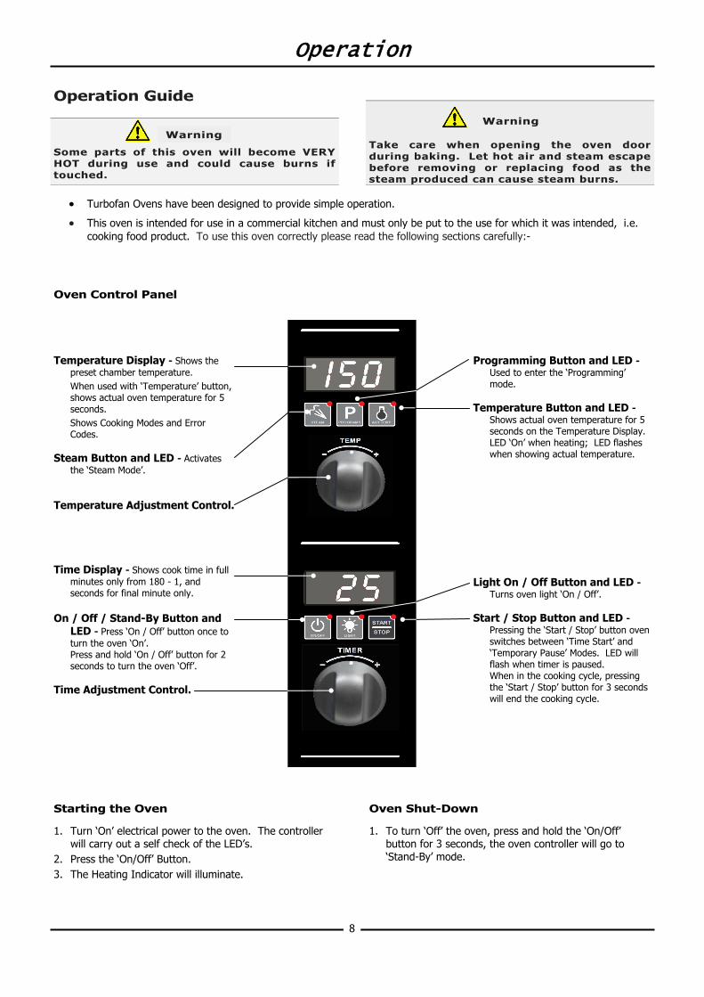
Oven Control Panel
Starting the Oven
1. Turn ‘On’ electrical power to the oven. The controller will carry out a self check of the LED’s.
2. Press the ‘On/Off’ Button. 3. The Heating Indicator will illuminate.
Oven Shut-Down
1. To turn ‘Off’ the oven, press and hold the ‘On/Off’ button for 3 seconds, the oven controller will go to ‘Stand-By’ mode.
Temperature Display - Shows the preset chamber temperature. When used with ‘Temperature’ button, shows actual oven temperature for 5 seconds. Shows Cooking Modes and Error Codes.
Steam Button and LED - Activates
the ‘Steam Mode’. Temperature Adjustment Control. Time Display - Shows cook time in full
minutes only from 180 - 1, and seconds for final minute only.
On / Off / Stand-By Button and
LED - Press ‘On / Off’ button once to turn the oven ‘On’.
Press and hold ‘On / Off’ button for 2 seconds to turn the oven ‘Off’.
Time Adjustment Control.
Programming Button and LED - Used to enter the ‘Programming’ mode.
Temperature Button and LED -
Shows actual oven temperature for 5 seconds on the Temperature Display.
LED ‘On’ when heating; LED flashes when showing actual temperature.
Light On / Off Button and LED -
Turns oven light ‘On / Off’. Start / Stop Button and LED -
Pressing the ‘Start / Stop’ button oven switches between ‘Time Start’ and ‘Temporary Pause’ Modes. LED will flash when timer is paused.
When in the cooking cycle, pressing the ‘Start / Stop’ button for 3 seconds will end the cooking cycle.
Some parts of this oven will become VERY HOT during use and could cause burns if touched.
Warning Take care when opening the oven door during baking. Let hot air and steam escape before removing or replacing food as the steam produced can cause steam burns.
Warning
Operation
9
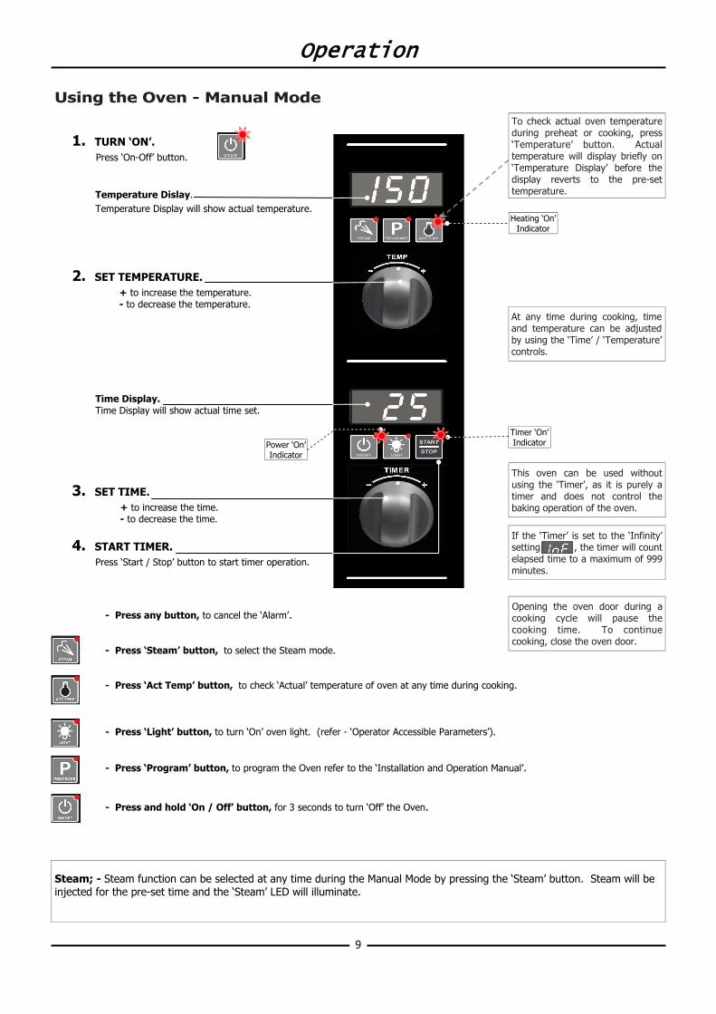
Using the Oven - Manual Mode
1. TURN ‘ON’.
Press ‘On-Off’ button.
Temperature Dislay. Temperature Display will show actual temperature.
2. SET TEMPERATURE.
+ to increase the temperature. - to decrease the temperature.
Time Display. Time Display will show actual time set.
3. SET TIME. + to increase the time. - to decrease the time.
4. START TIMER. Press ‘Start / Stop’ button to start timer operation.
- Press any button, to cancel the ‘Alarm’. - Press ‘Steam’ button, to select the Steam mode. - Press ‘Act Temp’ button, to check ‘Actual’ temperature of oven at any time during cooking. - Press ‘Light’ button, to turn ‘On’ oven light. (refer - ‘Operator Accessible Parameters’). - Press ‘Program’ button, to program the Oven refer to the ‘Installation and Operation Manual’. - Press and hold ‘On / Off’ button, for 3 seconds to turn ‘Off’ the Oven.
Timer ‘On’ Indicator
Heating ‘On’ Indicator
To check actual oven temperature during preheat or cooking, press ‘Temperature’ button. Actual temperature will display briefly on ‘Temperature Display’ before the display reverts to the pre-set temperature.
At any time during cooking, time and temperature can be adjusted by using the ‘Time’ / ‘Temperature’ controls.
Opening the oven door during a cooking cycle will pause the cooking time. To continue cooking, close the oven door.
This oven can be used without using the ‘Timer’, as it is purely a timer and does not control the baking operation of the oven.
Steam; - Steam function can be selected at any time during the Manual Mode by pressing the ‘Steam’ button. Steam will be injected for the pre-set time and the ‘Steam’ LED will illuminate.
If the ‘Timer’ is set to the ‘Infinity’ setting , the timer will count elapsed time to a maximum of 999 minutes.
Power ‘On’ Indicator
Operation
10
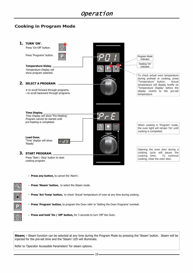
Cooking in Program Mode
1. TURN ‘ON’.
Press ‘On-Off’ button. Press ‘Programs’ button.
Temperature Dislay. Temperature Display will show program selected.
2. SELECT A PROGRAM. + to scroll forward through programs. - to scroll backward through programs.
Time Display. Time Display will show ‘Pre-Heating’. Program cannot be started until pre-heating is completed.
Load Oven. ‘Time’ display will show ‘Ready’.
3. START PROGRAM. Press ‘Start / Stop’ button to start cooking program.
- Press any button, to cancel the ‘Alarm’. - Press ‘Steam’ button, to select the Steam mode. - Press ‘Act Temp’ button, to check ‘Actual’ temperature of oven at any time during cooking. - Press ‘Program’ button, to program the Oven refer to ‘Setting the Oven Programs’ overleaf. - Press and hold ‘On / Off’ button, for 3 seconds to turn ‘Off’ the Oven.
To check actual oven temperature during preheat or cooking, press ‘Temperature’ button. Actual temperature will display briefly on ‘Temperature Display’ before the display reverts to the pre-set temperature.
Opening the oven door during a cooking cycle will pause the cooking time. To continue cooking, close the oven door.
Heating ‘On’ Indicator
When cooking in ‘Program’ mode, the oven light will remain ‘On’ until cooking is completed.
Program Mode Indicator
Steam; - Steam function can be selected at any time during the Program Mode by pressing the ‘Steam’ button. Steam will be injected for the pre-set time and the ‘Steam’ LED will illuminate. Refer to ‘Operator Accessible Parameters’ for steam options.
Operation
11
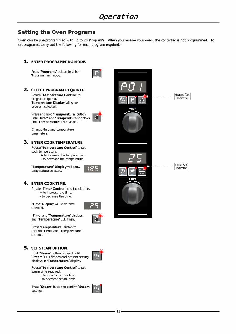
Setting the Oven Programs
Oven can be pre-programmed with up to 20 Program’s. When you receive your oven, the controller is not programmed. To set programs, carry out the following for each program required:-
1. ENTER PROGRAMMING MODE.
Press ‘Programs’ button to enter ‘Programming’ mode.
2. SELECT PROGRAM REQUIRED. Rotate ‘Temperature Control’ to program required. Temperature Display will show program selected.
Press and hold ‘Temperature’ button until ‘Time’ and ‘Temperature’ displays and ‘Temperature’ LED flashes. Change time and temperature parameters.
3. ENTER COOK TEMPERATURE. Rotate ‘Temperature Control’ to set cook temperature.
+ to increase the temperature. - to decrease the temperature.
‘Temperature’ Display will show temperature selected.
4. ENTER COOK TIME. Rotate ‘Timer Control’ to set cook time.
+ to increase the time. - to decrease the time.
‘Time’ Display will show time selected. ‘Time’ and ‘Temperature’ displays and ‘Temperature’ LED flash. Press ‘Temperature’ button to confirm ‘Time’ and ‘Temperature’ settings.
5. SET STEAM OPTION.
Hold ‘Steam’ button pressed until ‘Steam’ LED flashes and present setting displays in ‘Temperature’ display. Rotate ‘Temperature Control’ to set steam time required.
+ to increase steam time. - to decrease steam time.
Press ‘Steam’ button to confirm ‘Steam’ settings.
Timer ‘On’ Indicator
Heating ‘On’ Indicator
Operation
12
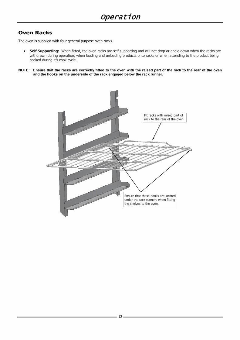
Oven Racks
The oven is supplied with four general purpose oven racks.
• Self Supporting: When fitted, the oven racks are self supporting and will not drop or angle down when the racks are withdrawn during operation, when loading and unloading products onto racks or when attending to the product being cooked during it’s cook cycle.
NOTE: Ensure that the racks are correctly fitted to the oven with the raised part of the rack to the rear of the oven
and the hooks on the underside of the rack engaged below the rack runner.
Ensure that these hooks are located under the rack runners when fitting the shelves to the oven.
Fit racks with raised part of rack to the rear of the oven
Operator Accessible Parameters
13
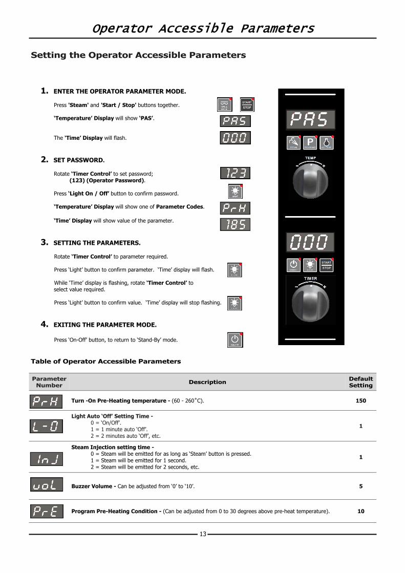
Setting the Operator Accessible Parameters
1. ENTER THE OPERATOR PARAMETER MODE.
Press 'Steam' and 'Start / Stop' buttons together. ‘Temperature’ Display will show ‘PAS’. The ‘Time’ Display will flash.
2. SET PASSWORD. Rotate ‘Timer Control’ to set password; (123) (Operator Password). Press ‘Light On / Off’ button to confirm password. ‘Temperature’ Display will show one of Parameter Codes. ‘Time’ Display will show value of the parameter.
3. SETTING THE PARAMETERS. Rotate ‘Timer Control’ to parameter required. Press ‘Light’ button to confirm parameter. ‘Time’ display will flash. While ‘Time’ display is flashing, rotate ‘Timer Control’ to select value required. Press ‘Light’ button to confirm value. ‘Time’ display will stop flashing.
4. EXITING THE PARAMETER MODE.
Press ‘On-Off’ button, to return to ‘Stand-By’ mode.
Table of Operator Accessible Parameters
Parameter Number Description Default
Setting
Turn -On Pre-Heating temperature - (60 - 260˚C). 150
Light Auto ‘Off’ Setting Time - 0 = ‘On/Off’. 1 = 1 minute auto ‘Off’. 2 = 2 minutes auto ‘Off’, etc.
1
Steam Injection setting time - 0 = Steam will be emitted for as long as ‘Steam’ button is pressed. 1 = Steam will be emitted for 1 second. 2 = Steam will be emitted for 2 seconds, etc.
1
Buzzer Volume - Can be adjusted from ‘0’ to ‘10’. 5
Program Pre-Heating Condition - (Can be adjusted from 0 to 30 degrees above pre-heat temperature). 10
Cleaning
14
Cleaning Guidelines
To achieve the best results, cleaning must be regular and thorough. If any small faults occur, have them looked at promptly. Don't wait until they cause a complete breakdown.
NOTE:
• Carefully read and follow the safety instructions on the label of the cleaning product to be used.
• DO NOT use harsh abrasive scouring pads or abrasive detergents as they could damage the oven.
• Ensure that any detergent or cleaning material has been completely removed after each cleaning.
To keep your oven clean and operating at peak efficiency, follow the procedures shown below:- Oven Cleaning
NOTE: • If oven usage is very high, the cleaning procedure
should be carried out on a more frequent basis.
• Allow the oven interior to cool to approx 50˚C / 120˚F before commencing cleaning.
Stainless Steel Surfaces a. Thoroughly clean the exterior surfaces of the oven
with, a damp cloth moistened with a mild detergent solution, or a soft bristled brush.
b. Baked on deposits or discolouration may require a good quality stainless steel cleaner. Always apply cleaner when the oven is cold and rub in the direction of the grain.
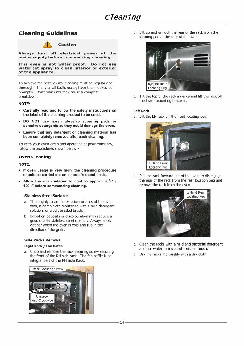
Side Racks Removal Right Rack / Fan Baffle
a. Undo and remove the rack securing screw securing the front of the RH side rack. The fan baffle is an integral part of the RH Side Rack.
b. Lift up and unhook the rear of the rack from the locating peg at the rear of the oven.
c. Tilt the top of the rack inwards and lift the rack off the lower mounting brackets.
Left Rack
a. Lift the LH rack off the front locating peg.
b. Pull the rack forward out of the oven to disengage the rear of the rack from the rear location peg and remove the rack from the oven.
c. Clean the racks with a mild anti bacterial detergent and hot water, using a soft bristled brush.
d. Dry the racks thoroughly with a dry cloth.
Always turn off electrical power at the mains supply before commencing cleaning. This oven is not water proof. Do not use water jet spray to clean interior or exterior of the appliance.
Caution
R/Hand Rear Locating Peg
L/Hand Front Locating Peg
L/Hand Rear Locating Peg
Unscrew Anti-Clockwise
Rack Securing Screw
Cleaning
15
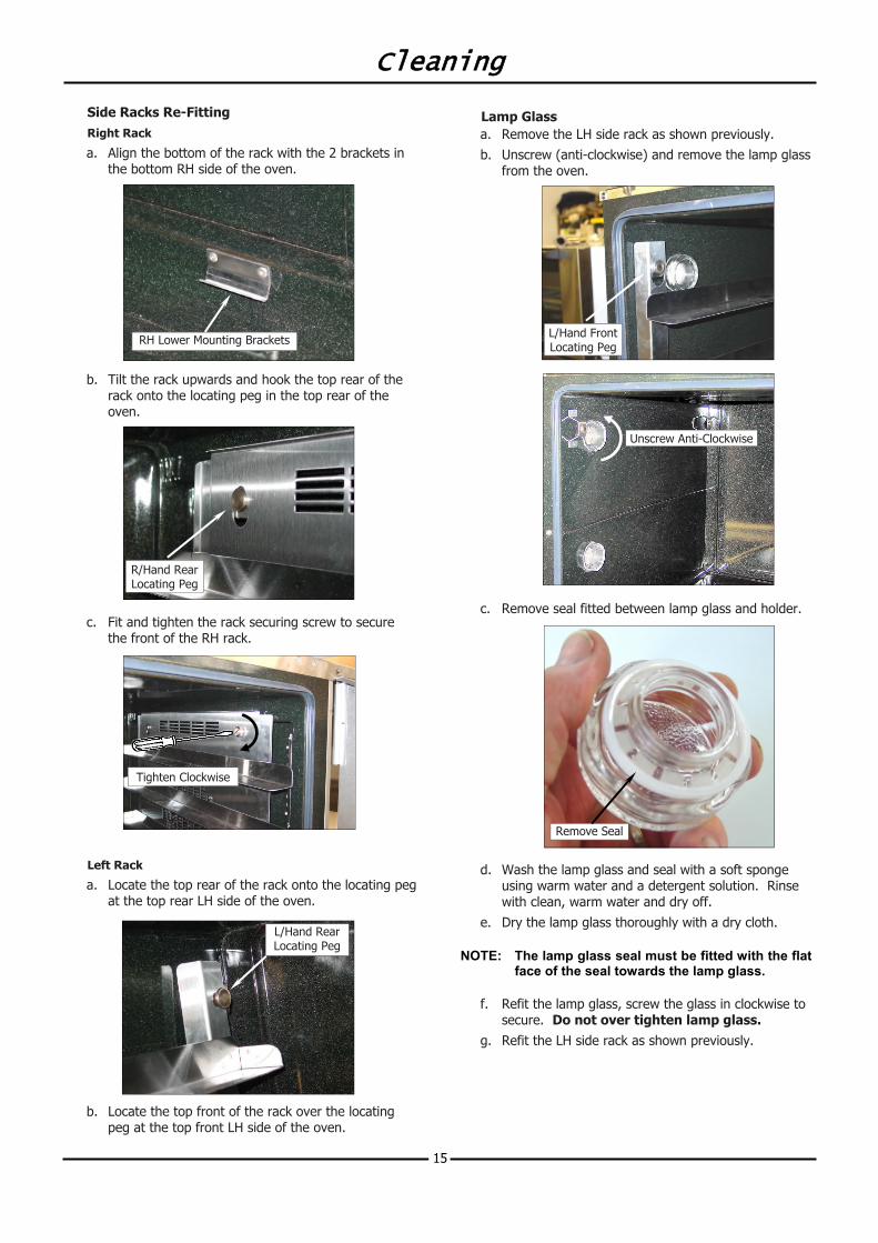
Side Racks Re-Fitting Right Rack
a. Align the bottom of the rack with the 2 brackets in the bottom RH side of the oven.
b. Tilt the rack upwards and hook the top rear of the rack onto the locating peg in the top rear of the oven.
c. Fit and tighten the rack securing screw to secure the front of the RH rack.
Left Rack
a. Locate the top rear of the rack onto the locating peg at the top rear LH side of the oven.
b. Locate the top front of the rack over the locating peg at the top front LH side of the oven.
Lamp Glass a. Remove the LH side rack as shown previously. b. Unscrew (anti-clockwise) and remove the lamp glass
from the oven.
c. Remove seal fitted between lamp glass and holder.
d. Wash the lamp glass and seal with a soft sponge using warm water and a detergent solution. Rinse with clean, warm water and dry off.
e. Dry the lamp glass thoroughly with a dry cloth. NOTE: The lamp glass seal must be fitted with the flat
face of the seal towards the lamp glass.
f. Refit the lamp glass, screw the glass in clockwise to secure. Do not over tighten lamp glass.
g. Refit the LH side rack as shown previously.
Unscrew Anti-Clockwise
Remove Seal
RH Lower Mounting Brackets
R/Hand Rear Locating Peg
L/Hand Rear Locating Peg
L/Hand Front Locating Peg
Tighten Clockwise
Cleaning
16
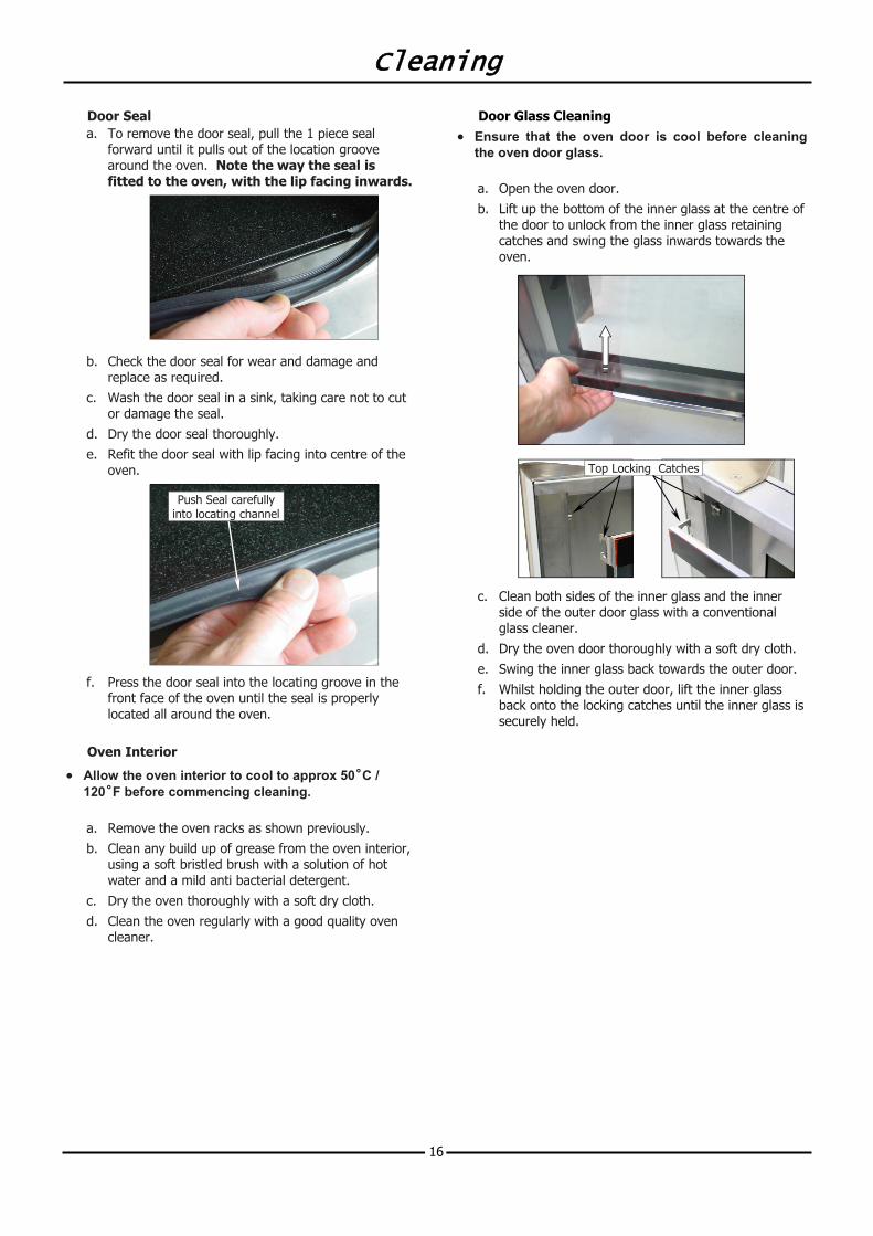
Door Seal a. To remove the door seal, pull the 1 piece seal
forward until it pulls out of the location groove around the oven. Note the way the seal is fitted to the oven, with the lip facing inwards.
b. Check the door seal for wear and damage and replace as required.
c. Wash the door seal in a sink, taking care not to cut or damage the seal.
d. Dry the door seal thoroughly. e. Refit the door seal with lip facing into centre of the
oven.
f. Press the door seal into the locating groove in the front face of the oven until the seal is properly located all around the oven.
Oven Interior
• Allow the oven interior to cool to approx 50˚C / 120˚F before commencing cleaning.
a. Remove the oven racks as shown previously. b. Clean any build up of grease from the oven interior,
using a soft bristled brush with a solution of hot water and a mild anti bacterial detergent.
c. Dry the oven thoroughly with a soft dry cloth. d. Clean the oven regularly with a good quality oven
cleaner.
Push Seal carefully into locating channel
Door Glass Cleaning • Ensure that the oven door is cool before cleaning
the oven door glass.
a. Open the oven door. b. Lift up the bottom of the inner glass at the centre of
the door to unlock from the inner glass retaining catches and swing the glass inwards towards the oven.
c. Clean both sides of the inner glass and the inner side of the outer door glass with a conventional glass cleaner.
d. Dry the oven door thoroughly with a soft dry cloth. e. Swing the inner glass back towards the outer door. f. Whilst holding the outer door, lift the inner glass
back onto the locking catches until the inner glass is securely held.
Top Locking Catches
Fault Finding
17
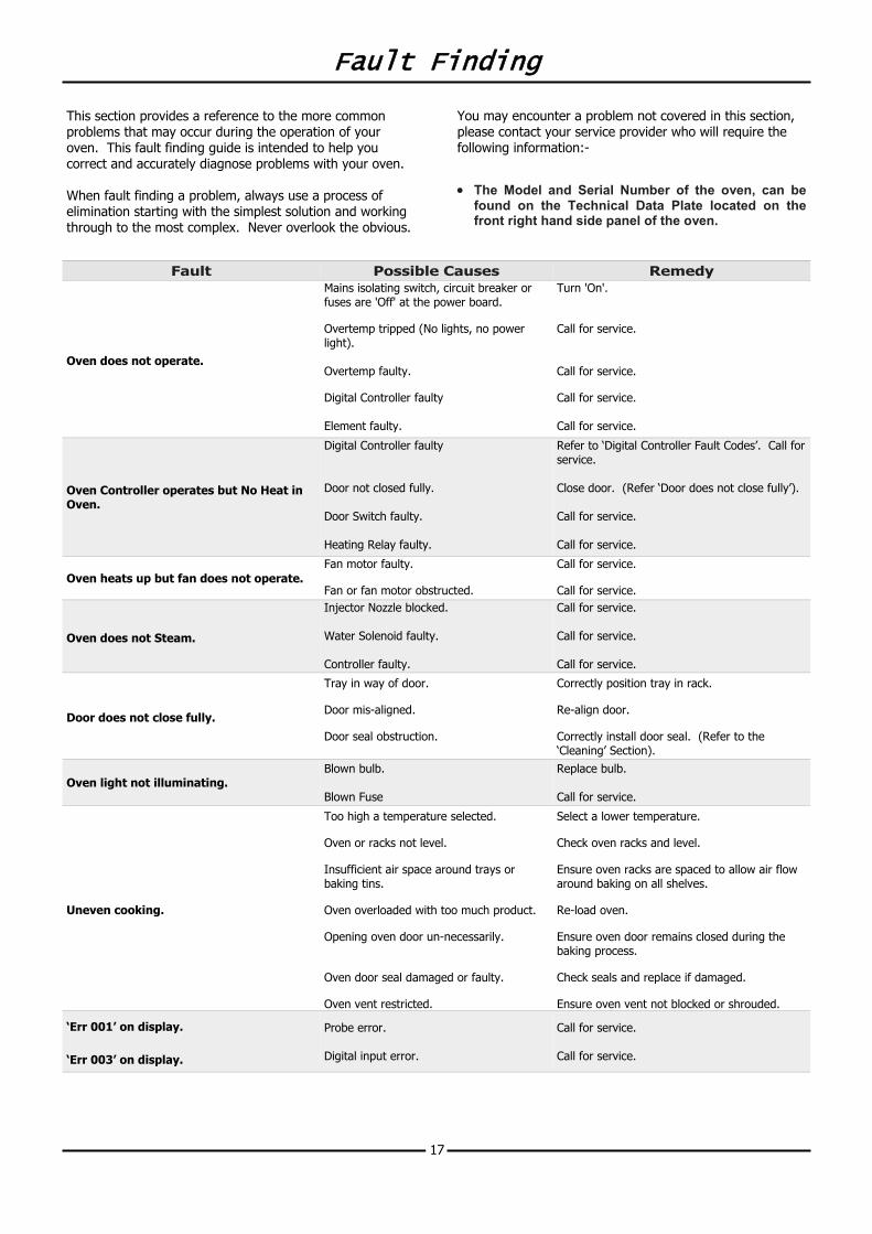
This section provides a reference to the more common problems that may occur during the operation of your oven. This fault finding guide is intended to help you correct and accurately diagnose problems with your oven. When fault finding a problem, always use a process of elimination starting with the simplest solution and working through to the most complex. Never overlook the obvious.
You may encounter a problem not covered in this section, please contact your service provider who will require the following information:-
• The Model and Serial Number of the oven, can be found on the Technical Data Plate located on the front right hand side panel of the oven.
Fault Possible Causes Remedy
Oven does not operate.
Mains isolating switch, circuit breaker or fuses are 'Off' at the power board. Overtemp tripped (No lights, no power light). Overtemp faulty. Digital Controller faulty Element faulty.
Turn 'On'. Call for service. Call for service. Call for service. Call for service.
Oven heats up but fan does not operate. Fan motor faulty. Fan or fan motor obstructed.
Call for service. Call for service.
Door does not close fully.
Tray in way of door. Door mis-aligned. Door seal obstruction.
Correctly position tray in rack. Re-align door. Correctly install door seal. (Refer to the ‘Cleaning’ Section).
Oven light not illuminating. Blown bulb. Blown Fuse
Replace bulb. Call for service.
Uneven cooking.
Too high a temperature selected. Oven or racks not level. Insufficient air space around trays or baking tins. Oven overloaded with too much product. Opening oven door un-necessarily. Oven door seal damaged or faulty. Oven vent restricted.
Select a lower temperature. Check oven racks and level. Ensure oven racks are spaced to allow air flow around baking on all shelves. Re-load oven. Ensure oven door remains closed during the baking process. Check seals and replace if damaged. Ensure oven vent not blocked or shrouded.
Oven does not Steam.
Injector Nozzle blocked. Water Solenoid faulty. Controller faulty.
Call for service. Call for service. Call for service.
Oven Controller operates but No Heat in Oven.
Digital Controller faulty Door not closed fully. Door Switch faulty. Heating Relay faulty.
Refer to ‘Digital Controller Fault Codes’. Call for service. Close door. (Refer ‘Door does not close fully’). Call for service. Call for service.
‘Err 001’ on display. ‘Err 003’ on display.
Probe error. Digital input error.
Call for service. Call for service.
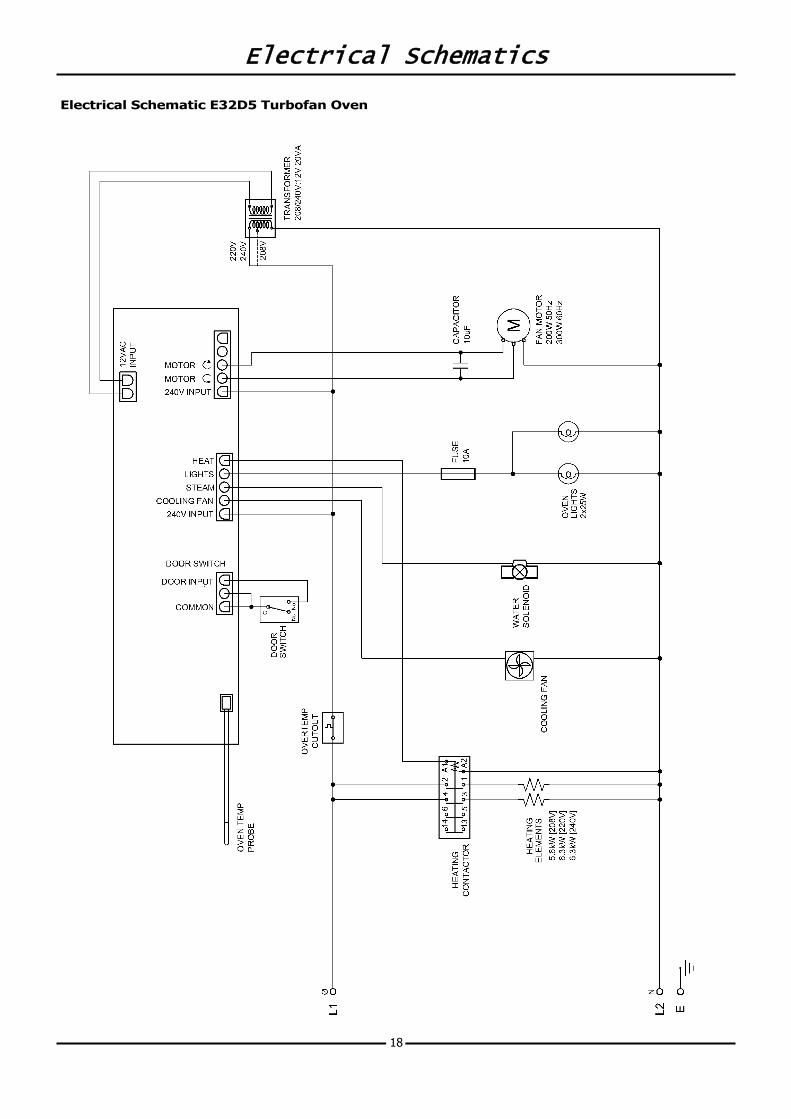
Electrical Schematics
18
Electrical Schematic E32D5 Turbofan Oven
Replacement Parts List
19
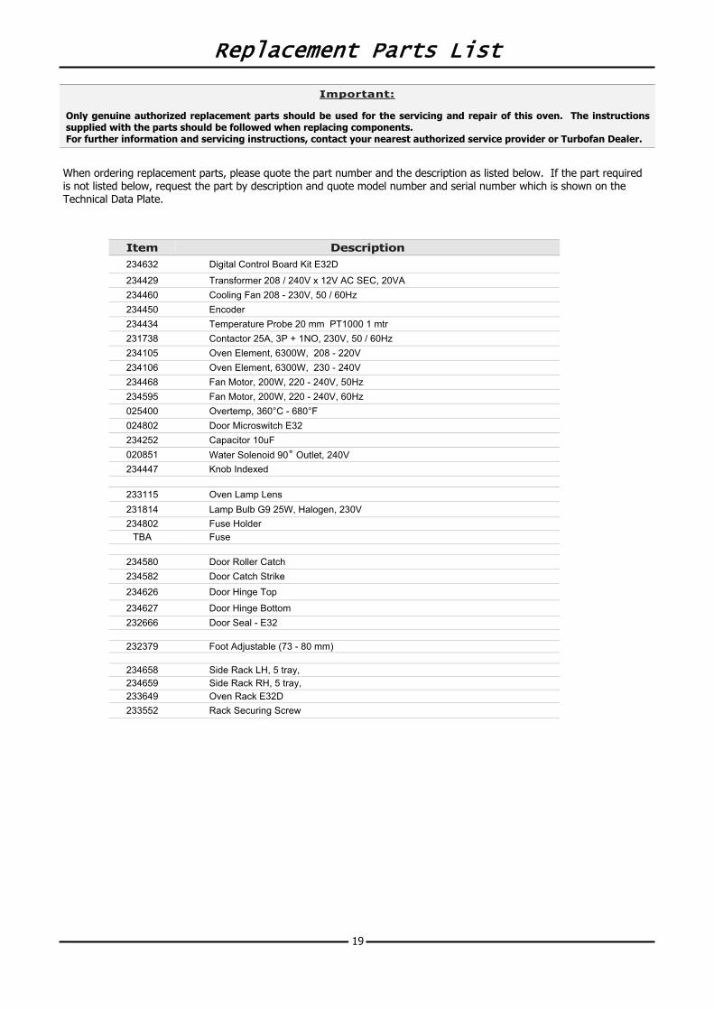
When ordering replacement parts, please quote the part number and the description as listed below. If the part required is not listed below, request the part by description and quote model number and serial number which is shown on the Technical Data Plate.
Important:
Only genuine authorized replacement parts should be used for the servicing and repair of this oven. The instructions supplied with the parts should be followed when replacing components. For further information and servicing instructions, contact your nearest authorized service provider or Turbofan Dealer.
Item Description 234632 Digital Control Board Kit E32D
234429 Transformer 208 / 240V x 12V AC SEC, 20VA 234460 Cooling Fan 208 - 230V, 50 / 60Hz 234450 Encoder 234434 Temperature Probe 20 mm PT1000 1 mtr 231738 Contactor 25A, 3P + 1NO, 230V, 50 / 60Hz 234105 Oven Element, 6300W, 208 - 220V 234106 Oven Element, 6300W, 230 - 240V 234468 Fan Motor, 200W, 220 - 240V, 50Hz 234595 Fan Motor, 200W, 220 - 240V, 60Hz 025400 Overtemp, 360°C - 680°F 024802 Door Microswitch E32 234252 Capacitor 10uF 020851 Water Solenoid 90˚ Outlet, 240V 234447 Knob Indexed
233115 Oven Lamp Lens 231814 Lamp Bulb G9 25W, Halogen, 230V
234580 Door Roller Catch 234582 Door Catch Strike 234626 Door Hinge Top
234627 Door Hinge Bottom 232666 Door Seal - E32
232379 Foot Adjustable (73 - 80 mm)
234658 Side Rack LH, 5 tray, 234659 Side Rack RH, 5 tray, 233649 Oven Rack E32D 233552 Rack Securing Screw
234802 Fuse Holder TBA Fuse