Embed Size (px)
Citation preview

INSTALLATION ANDOPERATION MANUAL
Central control for hydroboxes
EKCC7-W
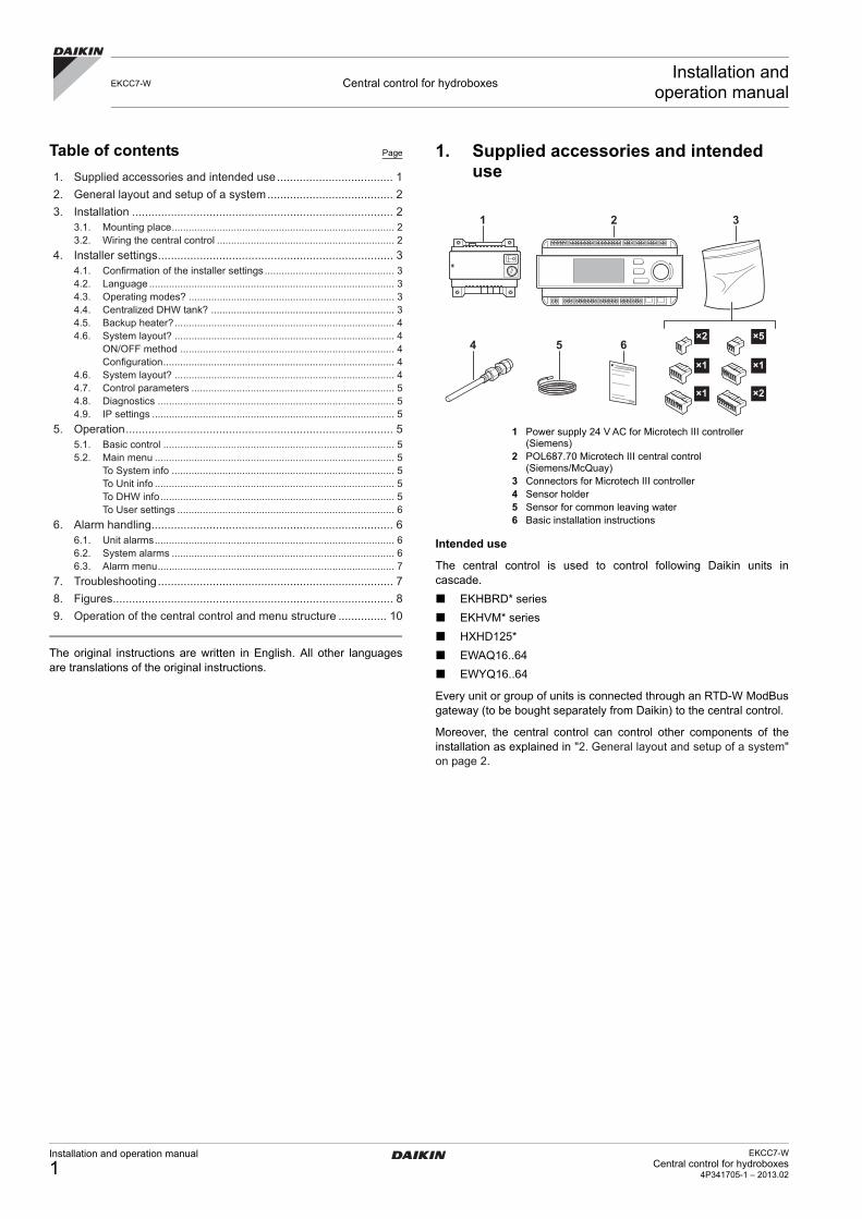
Table of contents Page
1. Supplied accessories and intended use .................................... 1
2. General layout and setup of a system....................................... 2
3. Installation ................................................................................. 23.1. Mounting place............................................................................... 23.2. Wiring the central control ............................................................... 2
4. Installer settings......................................................................... 34.1. Confirmation of the installer settings .............................................. 34.2. Language ....................................................................................... 34.3. Operating modes? ......................................................................... 34.4. Centralized DHW tank? ................................................................. 34.5. Backup heater?.............................................................................. 44.6. System layout? .............................................................................. 4
ON/OFF method ............................................................................ 4Configuration.................................................................................. 4
4.6. System layout? .............................................................................. 44.7. Control parameters ........................................................................ 54.8. Diagnostics .................................................................................... 54.9. IP settings ...................................................................................... 5
5. Operation................................................................................... 55.1. Basic control .................................................................................. 55.2. Main menu ..................................................................................... 5
To System info ............................................................................... 5To Unit info ..................................................................................... 5To DHW info................................................................................... 5To User settings ............................................................................. 6
6. Alarm handling........................................................................... 66.1. Unit alarms..................................................................................... 66.2. System alarms ............................................................................... 66.3. Alarm menu.................................................................................... 7
7. Troubleshooting......................................................................... 7
8. Figures....................................................................................... 8
9. Operation of the central control and menu structure ............... 10
The original instructions are written in English. All other languagesare translations of the original instructions.
1. Supplied accessories and intended use
1 Power supply 24 V AC for Microtech III controller (Siemens)
2 POL687.70 Microtech III central control (Siemens/McQuay)
3 Connectors for Microtech III controller4 Sensor holder5 Sensor for common leaving water6 Basic installation instructions
Intended use
The central control is used to control following Daikin units incascade.
EKHBRD* series
EKHVM* series
HXHD125*
EWAQ16..64
EWYQ16..64
Every unit or group of units is connected through an RTD-W ModBusgateway (to be bought separately from Daikin) to the central control.
Moreover, the central control can control other components of theinstallation as explained in "2. General layout and setup of a system"on page 2.
EKCC7-W Central control for hydroboxesInstallation and
operation manual
1 2 3
4 5 6×2
×1
×1
×5
×1
×2
Installation and operation manual
1EKCC7-W
Central control for hydroboxes4P341705-1 – 2013.02

2. General layout and setup of a system
The central control can control the following in a system:
Leaving water temperature to the secondary circuit (circuit to theheat emitters)The setpoint for the leaving water temperature to the secondarycircuit can be set. The central control will change the setpoint ofthe units and switch more or less units ON/OFF in order to reachthis setpoint.
Pump of the secondary circuit
Backup heater for room heating
Domestic hot water temperature in a centralized domestic hotwater tank
In case of a system with domestic hot water, the system can be setup in 2 ways:
1. System with integrated hot water tank(s)In this case, the units for domestic hot water have their owntank, 3-way valve and 3-way valve control. The parameters forheating domestic hot water (setpoint, schedule, etc.) must be seton the control of the unit itself. Refer to the operation/installationmanual of the unit.On the central control, you can define whether a unit hasdomestic hot water function or not. (This can be defined in theinstaller settings. Refer to "Configuration" on page 4.)If the unit is defined as a unit for domestic hot water, it willalways get the lowest priority to start up during room heating, inorder to reserve it as much as possible for DHW heating. Duringroom cooling, it will always get the highest priority in order torecover the heat to the DHW tank.Refer to Figure 3: System with integrated hot water tanks onpage 9 for a setup example.
1A~B Hydroboxes with integrated tank3~5 Hydroboxes/inverter chillers
A Domestic hot water tanks (EKHTS200/260)B Non-return valve (field supply)C Backup heater (field supply)D Leaving water temperature to secondary circuit sensor
(supplied with EKCC7-W)E Secondary circuit pump (field supply)F Central control (supplied with EKCC7-W)
When the system is set to heating or cooling (on the centralcontrol or by external contact connected to the central control),the central control will switch on the pump of the secondarycircuit and change the setpoint of the hydroboxes in order toreach the setpoint for the leaving water temperature to thesecondary circuit. In this example, units 1A and 1B arecontrolled together, since they are connected to the sameRTD-W.If the hydroboxes cannot reach the set temperature to thesecondary circuit and depending on other parameters set on thecentral control, the central control will also switch on the backupheater.
2. System with centralized domestic hot water tankIn this case, a tank sensor in the centralized tank is connected tothe central control. The central control will increase the setpointof the units and switch the 3-way valve when the temperature inthe tank becomes too low.
Refer to Figure 2: System with centralized domestic hot watertank on page 8 for a setup example.
1A~5 Hydroboxes/inverter chillersA Centralized domestic hot water tank (field supply)B Domestic hot water sensor (Daikin option: EKCLWS)C Non-return valve (field supply)D 3-way valve for DHW (field supply)E Backup heater with integrated pump (field supply)F Leaving water temperature to secondary circuit sensor
(supplied with EKCC7-W)G Secondary circuit pump (field supply)H Central control (supplied with EKCC7-W)
When the system is set to heating or cooling (on the centralcontrol or by external contact connected to the central control),the central control will switch on the pump of the secondarycircuit, switch the hydroboxes ON/OFF and change the setpointin order to reach the setpoint for the leaving water temperatureto the secondary circuit. In this example, units 1A and 1B arecontrolled together, since they are connected to the sameRTD-W.If the hydroboxes cannot reach the set temperature to thesecondary circuit and depending on other parameters set on thecentral control, the central control will also switch on the backupheater.When domestic hot water heating is required, the central controlwill switch the 3-way valve for DHW and increase the setpoint ofunits 1A and 1B until the required domestic hot watertemperature is reached.
3. Installation
3.1. Mounting place
When the central control is ON, the units will be controlled (setpointsetting, ON/OFF control, etc.) by the central control. This will overrulethe ON/OFF setting on the individual remote controllers. For ON/OFFcontrol using the remote controllers of the units, the central controlmust be set to OFF. In order to allow local control of the units at alltimes, the central control must be installed in the vicinity of theindividual remote controllers.
3.2. Wiring the central control
Also refer to Figure 1: Electrical wiring diagram on page 8.
Modbus wiringThe control uses Modbus to communicate with the hydroboxes.Make sure to wire the RS485 wiring (2-wire twisted pair + shield)from the central control to the RTD-Ws.Also make sure to configure the addresses on the RTD-Wcorrectly (refer to RTD-W manual).
Digital inputsIn order to start the system in heating/cooling by an externalvoltage free contact, wire the following digital inputs:- DI1-M (T10): Heating ON- DI2-M (T10): Cooling ON
- X1-M(T8): This voltage free input changes the value of the outdoor temperature at which the backup heater is allowed to operate. Also refer to "4.5. Backup heater?" on page 4.
- X2-M(T8): This voltage free input detects alarms of the backup heater.
INFORMATION
This means that the units are put in heating mode toheat the DHW tank. For this reason, this setup is onlyapplicable to EKHBRD*AC units set to configuration C(refer to ‘Application guide Altherma Flex forcommercial applications’).
This setup is not advised for EKHVM units, sinceheating mode is only possible up to an outdoortemperature of 25°C.
For EWYQ units, post-heating of domestic hot watermight be required, since the maximum leaving watertemperature of these units is limited to 55°C.
WARNING
All electrical wiring must be installed by a licensedelectrician and must comply with local regulations.
INFORMATION
The central control can also be configured to startheating/cooling using the central control. In that case,it is not necessary to wire these contacts.
EKCC7-WCentral control for hydroboxes4P341705-1 – 2013.02
Installation and operation manual
2

Analog inputs- AI1-M(T7): Common leaving water sensor. This sensor
measures the leaving water temperature to the secondary circuit. (Supplied with EKCC7-W).
- AI2-M(T7): Domestic hot water temperature. (Daikin option EKCLWS). Only if you have a centralized tank and DHW must be controlled by the central control.
Digital outputs- C3-DO3(T3): Contact to start the secondary pump. This
contact closes whenever heating or cooling is ON.- C4-DO4(T3): Contact to energize the 3-way valve for DHW.
This contact closes when DHW heating is requested.- C5-DO5(T4): Contact to start the backup heater. This contact
closes when backup heater operation is requested.- C8-DO8(T4): This contact closes when there is an alarm in
the system (e.g. one of the heatpump units is in alarm, faulty common leaving water sensor, etc.).
- C9-DO9(T5): Heating operation. This contact closes when the system is in room heating mode.
- C10-D010(T5): Cooling operation. This contact closes when the system is in room cooling mode.
4. Installer settings
Refer to "9. Operation of the central control and menu structure" onpage 10 for basic operation of the central control.All items in the ‘Installer settings’ menu are explained below in detail.To make the installer settings available, scroll to ‘Installer password’in the main menu and enter the installer password (default: ‘6000’)and then go to the ‘Installer settings’ menu.
4.1. Confirmation of the installer settings
Some settings require a restart of the central control in order tobecome effective. This is indicated in the first line of the ‘Installersettings’ menu. When this line shows ‘Restart now?’, changes weremade in the installer settings that require a restart to becomeeffective. Enter the line and select to restart the central control.When the line shows ‘No need to restart’, all changes are alreadyeffective.
4.2. Language
Select the desired language.
4.3. Operating modes?
Define the possible operating modes of the system.
Heating only/Cooling only/Heating and cooling
This will make sure the user can only select the appropriate modes.Restart the central control after changing these settings in order tomake them effective.
4.4. Centralized DHW tank?
Define if the system has a centralized DHW tank.
Only if the system has a centralized domestic hot water tank and fieldsupplied 3-way valve, select:
Centralized tank
And enter the desired value for:
DT LWT-SP tankThis value determines the temperature difference between thesetpoint of the leaving water temperature of the unit(s) and thesetpoint of the tank. The higher the value, the faster the tank canbe heated. The lower the value, the more efficiently the tank willbe heated.
DHW differentialDifferential for tank heating.
1 DHW differential2 SP tank (set by user)3 Start tank heating4 Stop tank heating
INFORMATION
Contact rating:
Switching voltage AC 24 V…230 V (–20%, +10%)
Rated current (res./ind.) Max. AC 3 A / 2 A (cos φ0.6)
Switching current at AC 19 V Min. AC 30 mA
Max. external supply line fusing 6.3 A slow wire fuse orcircuit breaker.
WARNING
Do not mix SELV/PELV and line voltage on the sameterminal.
Use external protection for inductive load.
4
3
21
Installation and operation manual
3EKCC7-W
Central control for hydroboxes4P341705-1 – 2013.02

4.5. Backup heater?
Define here if the system has a backup heater or not. If so, select‘Backup heating’ and define the backup heater method.
3 methods for the backup heating can be defined:
Method 1: Outd TempThe backup heater will be allowed to operate, depending on theoutdoor temperature.- BUH allowed: Below this temperature, BUH is allowed to
operate, but BUH has the lowest priority.Above this temperature, only heatpump units will run (even iftarget leaving water temperature cannot be reached, unlessa heatpump is in alarm, then also BUH will run.)
- BUH only: Below this outdoor temperature, all heatpump units will be stopped for room heating, and only BUH will operate for room heating.
1 At increasing outdoor temperature2 At decreasing outdoor temperature3 BUH only4 BUH allowed5 Outdoor temperatureA BUH-only zoneB BUH allowedC No BUH allowed
Method 2: Outd. Temp. + ext. contactsDefine the following settings:- With open contact
BUH allowed: Define the outdoor temperature for ‘BUHallowed’ with OPEN contact.BUH only: Define the outdoor temperature for ‘BUH only’ withOPEN contact.
- With closed contactBUH allowed: Define the outdoor temperature for ‘BUHallowed’ with CLOSED contact.BUH only: Define the outdoor temperature for ‘BUH only’ withCLOSED contact.
Method 3: Outd. Temp. + time- Time Zone 1
Define the outdoor temperature for ‘BUH allowed’ and ‘BUHonly’ from Time Zone 1 onwards.
- Time Zone 2Define the outdoor temperature for ‘BUH allowed’ and ‘BUHonly’ from Time Zone 2 onwards.
- Select time zonesSelect for every day of the week the time and zone (TimeZone 1=Z1/Time Zone 2=Z2)
4.6. System layout?
ON/OFF method
Define here if the system has to be set to off, heating or cooling onthe central control (refer to the ‘User settings’ menu > Set roommode) or by external contacts.
Configuration
Enter
No of units installed: The number of units installed.
Configure unit type autoWhen ‘YES’ is selected, the system will detect and configure theunit type (cooling only/heating only/reversible) automatically.
Unit configuration:For every unit, enter the following items (the number in the ‘Unit’column corresponds to the address on the RTD-W).• Group (GRP)
Enter which group the indoor unit belongs to. Units belongingto the same group are usually connected to the sameoutdoor unit, because the program will start up unitsbelonging to the same group first, before starting up unitsbelonging to another group. This is done in order to avoidseveral outdoor units running at the same time at low load.
• Type (TYP)It is recommended to configure the unit type automatically(see above). However, the type can be changed manually ifdesired. In this case, enter if the unit has cooling only,heating only or cooling and heating function.
• Domestic hot water (DHW)What happens when you enter yes (Y) depends on whetherthe domestic hot water is controlled by the central control ornot. (Refer to "2. General layout and setup of a system" onpage 2).If the domestic hot water function is controlled by the unit(s)itself (integrated tank) and DHW=Y for this unit, then this unitwill always get the lowest priority to start up in heating mode,in order to preserve it for domestic hot water heating. Incooling mode, it will get the highest priority in order to be ableto do heat recovery. Domestic hot water heating itself will bedone as configured on the remote controller of the unit.If the domestic hot water function is controlled by the centralcontrol (refer to Installer settings – Centralized DHW tank?),the units for domestic hot water must be configured toDHW=Y. When domestic hot water heating is requested, thecentral control will increase the setpoint for those units only.
1
2
3 4 5
A B
B C
C
A
1°C
INFORMATION
General note on schedule settings:
Settings with time 00:00 are neglected.
INFORMATION
The central control will show the maximum number ofunits that can be controlled. Only the unit numbersentered above have to be configured. After restartingthe central control, the list of units will be restricted tothe number of units installed.
EKCC7-WCentral control for hydroboxes4P341705-1 – 2013.02
Installation and operation manual
4
4.7. Control parameters
Diff. LWT Heat On/Off and Diff. LWT Cool On/OffDefines the differential above/below which the system takesaction to switch units ON or OFF. (TempxTime counter is started,see below).
Temperature increase slaves (Temp. Incr. slaves)This parameter determines the increase (heating)/decrease(cooling) for the slaves. The setpoint of the ‘leading’ unit will beequal to the setpoint of the leaving water temperature to thesecondary circuit. The setpoint of the slaves will be the setpointof the leaving water temperature to the secondary circuit plustemperature increase slaves (minus temperature increaseslaves in cooling). This will lead to fully loading up of the slaveunits, and capacity control by the leading unit.
TempxTime for ON and OFFDefines the temperature×time value that must be exceededbefore a unit is switched ON or OFF. A low value will result infast switching ON/OFF, a high value will result in slow switchingON/OFF.
Start delay units (seconds)Defines the time that must expire before the control starts theTempxTime ON counter as explained above, after a unit hasstarted. Since the units need time to build up capacity, it isadvised to keep this value above 500 seconds.
Corr. CLWT sensorThis is a correction value for the common leaving water sensor.
P-heating/P-coolingInfluences the number of units to be started up at the same time(with an interval of about 10 seconds) when heating or cooling isstarted. A low value will result in more units starting up, a highervalue in less.The number of units starting up when heating or cooling isswitched ON is calculated as follows:
e.g.: SP leaving water temp=50°CLeaving water temp at startup=22°CNumber of units in system=12P-heating=50°C→ ((50–22)/50)*12=7 units will be started up at a time (with atime difference of about 10 seconds)
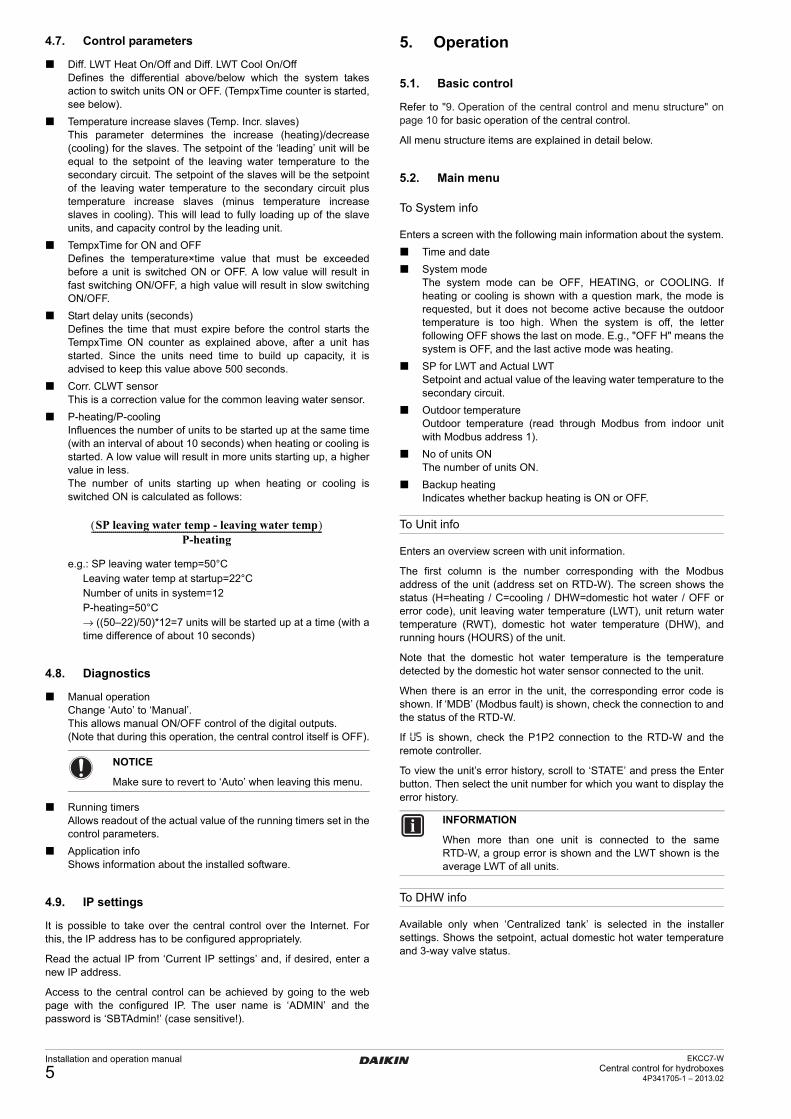
4.8. Diagnostics
Manual operationChange ‘Auto’ to ‘Manual’.This allows manual ON/OFF control of the digital outputs.(Note that during this operation, the central control itself is OFF).
Running timersAllows readout of the actual value of the running timers set in thecontrol parameters.
Application infoShows information about the installed software.
4.9. IP settings
It is possible to take over the central control over the Internet. Forthis, the IP address has to be configured appropriately.
Read the actual IP from ‘Current IP settings’ and, if desired, enter anew IP address.
Access to the central control can be achieved by going to the webpage with the configured IP. The user name is ‘ADMIN’ and thepassword is ‘SBTAdmin!’ (case sensitive!).
5. Operation
5.1. Basic control
Refer to "9. Operation of the central control and menu structure" onpage 10 for basic operation of the central control.
All menu structure items are explained in detail below.
5.2. Main menu
To System info
Enters a screen with the following main information about the system.
Time and date
System modeThe system mode can be OFF, HEATING, or COOLING. Ifheating or cooling is shown with a question mark, the mode isrequested, but it does not become active because the outdoortemperature is too high. When the system is off, the letterfollowing OFF shows the last on mode. E.g., "OFF H" means thesystem is OFF, and the last active mode was heating.
SP for LWT and Actual LWTSetpoint and actual value of the leaving water temperature to thesecondary circuit.
Outdoor temperatureOutdoor temperature (read through Modbus from indoor unitwith Modbus address 1).
No of units ONThe number of units ON.
Backup heatingIndicates whether backup heating is ON or OFF.
To Unit info
Enters an overview screen with unit information.
The first column is the number corresponding with the Modbusaddress of the unit (address set on RTD-W). The screen shows thestatus (H=heating / C=cooling / DHW=domestic hot water / OFF orerror code), unit leaving water temperature (LWT), unit return watertemperature (RWT), domestic hot water temperature (DHW), andrunning hours (HOURS) of the unit.
Note that the domestic hot water temperature is the temperaturedetected by the domestic hot water sensor connected to the unit.
When there is an error in the unit, the corresponding error code isshown. If ‘MDB’ (Modbus fault) is shown, check the connection to andthe status of the RTD-W.
If U5 is shown, check the P1P2 connection to the RTD-W and theremote controller.
To view the unit’s error history, scroll to ‘STATE’ and press the Enterbutton. Then select the unit number for which you want to display theerror history.
To DHW info
Available only when ‘Centralized tank’ is selected in the installersettings. Shows the setpoint, actual domestic hot water temperatureand 3-way valve status.
NOTICE
Make sure to revert to ‘Auto’ when leaving this menu.
SP leaving water temp - leaving water temp( )P-heating
--------------------------------------------------------------------------------------------------------------------
INFORMATION
When more than one unit is connected to the sameRTD-W, a group error is shown and the LWT shown is theaverage LWT of all units.
Installation and operation manual
5EKCC7-W
Central control for hydroboxes4P341705-1 – 2013.02

To User settings
Opens the ‘User settings’ menu with following items:
Time/dateEnter the correct time and date if you want to use the quietmode, room heating or DHW heating schedules.
Quiet modeSelect OFF, ON, or SCHEDULED.The central control will send the quiet mode command to theunits as selected. (Make sure to set the desired quiet mode levelon the units themselves. Refer to the installation manual of theunits – parameter [8-03].)A schedule for the quiet mode can be entered in the ‘Settings’menu (see below).
Set room modeSelect OFF, COOLING, or HEATING mode.If ‘By external contacts’ is selected in Installer settings - Systemlayout? - ON/OFF method, the mode cannot be selected on thecentral control, but only by external contacts.
Domestic hot waterSelect the domestic hot water mode.If set to ‘ON’, the domestic hot water will be heated inaccordance with the schedule that can be set in the ‘Settings’menu (see below).If ‘Reheat now?’ is set to ‘ON’, heating of the domestic hot waterwill be started immediately until the set reheat temperature(Reheat now till:) is reached.
Settings
Quiet mode scheduleEnter the quiet mode schedule for every day of the week.(1 = quiet mode activated)
Settings for room- Room heating
• Leaving water temp.Define the heating curve (leaving water temperature in function of outdoor temperature).
1 LWT at low Ta2 LWT at high Ta3 Low Ta4 High Ta
• Max. Ta heatingEnter the room temperature above which the system should not heat.
• LWT scheduleEnter the deviation from the heating curve in function of time.
- Room coolingAs above, but for cooling.
Settings for DHW
- DHW scheduleEnter the desired domestic hot water temperature in functionof time.
- Disinfect paramsEnter the desired disinfection temperature, disinfectionduration and day of the week and time to start disinfection.
The tank will be heated until the entered disinfection temperature foran (accumulated) time equal to the disinfection duration is reached.
6. Alarm handling
Unit alarms and system alarms can occur. For both types of alarm,the digital alarm output (C8-DO8) will be closed and an alarm will beindicated in the upper right corner of the display when an alarm isgenerated.
6.1. Unit alarms
When a unit alarm occurs, the central control will no longer use theunit (or group of units connected to the same RTD-W), and theremote controller of this unit (or group of units) will be set to OFF.This implies that the alarm can no longer be seen on the remotecontroller. (ON/OFF LED is OFF and no error code). However, thealarm can be seen on the central control in the 'Unit info' menu.
After the cause of the alarm is tackled, the unit has to be switched ONmanually (press the ON button on the remote controller). The unit willthen be controlled again by the central control and will switch ON orOFF as required.
6.2. System alarms
Following system alarms can occur:
Faulty common leaving water sensorWhen the common leaving water sensor indicates a value below0°C or above 150°C (open sensor), an alarm is generated andall units are switched ON in the currently requested mode up tothe currently requested setpoint.Units configured for heating a centralized DHW tank are alsoswitched to room heating, but when DHW heating is requested,the setpoint will be increased and the 3-way valve will beenergized, as in the normal DHW mode.
Faulty domestic hot water sensor (centralized tank)When the domestic hot water sensor indicates a value below0°C or above 150°C (open sensor), an alarm is generated andall units configured for DHW heating are operated for DHWheating and the DHW 3-way valve is energized when the DHWmode is requested.(The system operates as if it sees a DHW temperature thatnever reached the setpoint).
Backup heater alarmWhen the backup heater alarm is active (X2-M closed), an alarmis generated.
INFORMATION
Set the schedule timer on the units to OFF.
INFORMATION
General note on schedule settings:
Settings with time 00:00 are neglected.
INFORMATION
There is no need to define the setpoint on the units.The setpoint is transferred by the central control.Make sure the weather dependent function on theunits is set to OFF!
1
2
3 4
INFORMATION
This setting may also be available on the units. Makesure the setting on the unit is equal to or higher thanthe setting on the central control.
INFORMATION
This setting only needs to be done in case of acentralized tank! Centralized tank must be set in theinstaller settings for this menu to be accessible.
EKCC7-WCentral control for hydroboxes4P341705-1 – 2013.02
Installation and operation manual
6

6.3. Alarm menu
Press the alarm button to access the following screen:
Alarm listShows a list of the current alarms.
7. Troubleshooting
MDB is shown in the ‘Unit info’ menu.Make sure that the Modbus connection to the RTD-W with thecorresponding address is correct.Make sure that the correct number of connected units is definedin the installer settings.
U5 is shown in the ‘Unit info’ menu.Make sure that the P1P2 connection to the RTD-W with thecorresponding address is correct. If so, interrupt the power to theRTD-W and apply it again.
Some lines are not available in the menus.Interrupt the power to the EKCC7 central control, make thecorrect installer settings, and apply the power again.
Room mode cannot be set. The text "Not available. By externalcontacts" appears.Room mode can only be set by external contacts from thethermostat. To set the mode on the central control, change theinstaller settings.
Installation and operation manual
7EKCC7-W
Central control for hydroboxes4P341705-1 – 2013.02

8. Figures
Figure 1: Electrical wiring diagram
Figure 2: System with centralized domestic hot water tank
T7: AI1-MT7: AI2-M230 V
RTD-W RTD-W
T8: X1-MT8: X2-M
T3: C3-DO3T3: C4-DO4T4: C5-DO5T4: C8-DO8T5: C9-DO9
T5: C10-DO10
T10: DI1-MT10: DI2-M
AC 24...230 V (–20%, +10%)
Min. AC 30 mA
X1 M X2 DI1 M DI2
H
1A
A
BD
F G
E
1B
RTD-WRTD-W RTD-W RTD-W
3 4 5
C
EKCC7-WCentral control for hydroboxes4P341705-1 – 2013.02
Installation and operation manual
8

Figure 3: System with integrated hot water tanks
F
1A
B
D E
C
1B
A A
RTD-WRTD-W RTD-W RTD-W
3 4 5
Installation and operation manual
9EKCC7-W
Central control for hydroboxes4P341705-1 – 2013.02

9. Operation of the central control and menu structure
1 Alarm button: press this button to enter the alarm menu.
2 Main menu button: press this button to return to the ‘MAINMENU’ screen at all times.
3 Return button: press this button to return to the previous screen.
4 Select button: turn this button to scroll up and down through themenus. Press the button to enter your selection.
5 BSP LED. This LED should be green. See below for the possiblestates of the LED.
1 2 3
4
5
BSP LED status
Every second flashing between red and green
Download from SD card active
Green Application running
Yellow Application loaded but not running
Yellow flashing Application not loaded
Red flashing BSP error (software error)
Red ON Hardware error
EKCC7-WCentral control for hydroboxes4P341705-1 – 2013.02
Installation and operation manual
10

Screens shaded in gray are visible only depending on settings in the installer menu.
MAIN MENUTo System infoTo Unit infoTo DHW infoTo User settingsTo Installer settingsInstaller password
SYSTEM INFO15.02.2013 15:21:33System mode HeatingSP for LWT 30.0°CActual LWT 30.8°COutdoor temperature 9.0°CNr of units ON 0/3Backup heating OFF
MAIN MENUTo System infoTo Unit infoTo DHW infoTo User settingsTo Installer settingsInstaller password
UNIT INFOSTATE LWT RWT DHWT HOURS 1 H 50 45 50 199 2 H 50 45 400 3 OFF 31 32 440 4 A6 31 32 210
ERROR HISTORY UNITSELECT UNIT No 2 11/11/2012 10:38 A6
TIME/DATESELECT UNIT NR 2 21.11.2012 16:00:29
MAIN MENUTo System infoTo Unit infoTo DHW infoTo User settingsTo Installer settingsInstaller password
DHW INFODHW setpoint 60.0°CDHW temperature 58.6°CDHW 3-way valve OFF
MAIN MENUTo System infoTo Unit infoTo DHW infoTo User settingsTo Installer settingsInstaller password
USER SETTINGSTime/dateQuiet modeSet room modeDomestic hot waterSettings
TIME/DATESELECT UNIT NR 2
21.11.2012 16:00:29
QUIET MODE OFF
USER SETTINGSTime/dateQuiet modeSet room modeDomestic hot waterSettings
QUIET MODE SCHEDULED
SET ROOM MODE HEATING
USER SETTINGSTime/dateQuiet modeSet room modeDomestic hot waterSettings
SET ROOM MODE COOLING AND HEATING
SETTINGS FOR DHW Select DHW mode: ONReheat now? OFFReheat now till: 50°C
USER SETTINGSTime/dateQuiet modeSet room modeDomestic hot waterSettings
SETTINGS FOR DHW SELECT DHW MODE ON
SETTINGS FOR DHW Select DHW mode: ONReheat now? OFFReheat now till: 50°C
SETTINGS FOR DHW Reheat Now? OFF
SETTINGS FOR DHW Select DHW mode: ONReheat now? OFFReheat now till: 50°C
SETTINGS FOR DHW
Reheat Now till: 50°C
Installation and operation manual
11EKCC7-W
Central control for hydroboxes4P341705-1 – 2013.02

SETTINGS
Quiet mode scheduleSettings for roomSettings for DHW
USER SETTINGSTime/dateQuiet modeSet room modeDomestic hot waterSettings
QUIET MODE SCHEDULEMondayTuesdayWednesdayThursdayFridaySaturdaySunday
QUIET MODE SCHEDULE WednesdayTime 1 22:00 1Time 2 08:00 0Time 3 00:00 0Time 4 00:00 0Time 5 00:00 0Time 6 00:00 0
LWT SCHEDULE HEATINGMondayTuesdayWednesdayThursdayFridaySaturdaySunday
LWT SCHEDULE HEATING WednesdayTime 1 22:00 –10°CTime 2 06:00 0Time 3 00:00 0Time 4 00:00 0Time 5 00:00 0Time 6 00:00 0
SETTINGS FOR ROOM HEATING
Leaving water tempMax Ta heatingLWT schedule
DEFINE HEATING CURVE
Low Ta –10°CLWT at low Ta 60°C
High Ta 15°CLWT at high Ta 60°C
SETTINGS FOR ROOM HEATING
Leaving water tempMax Ta heatingLWT schedule
SETTINGS FOR ROOM HEATING
Leaving water tempMax Ta heatingLWT schedule
MAX. OUTDOOR FOR HEATING
Max Ta heating 20°C
LWT SCHEDULE COOLINGMondayTuesdayWednesdayThursdayFridaySaturdaySunday
LWT SCHEDULE COOLING WednesdayTime 1 22:00 10°CTime 2 06:00 0Time 3 00:00 0Time 4 00:00 0Time 5 00:00 0Time 6 00:00 0
SETTINGS FOR ROOM COOLING
Leaving water tempMin Ta coolingLWT schedule
SETTINGS FOR ROOM COOLING
Leaving water tempMin Ta coolingLWT schedule
MIN. OUTDOOR FOR COOLING
Min Ta cooling 20°C
SETTINGS
Quiet mode scheduleSettings for roomSettings for DHW
SETTINGS FOR ROOM
Room heatingRoom cooling
SETTINGS FOR ROOM COOLING
Leaving water tempMin Ta coolingLWT schedule
DEFINE COOLING CURVE
Low Ta 20°CLWT at low Ta 15°C
High Ta 30°CLWT at high Ta 8°C
USER SETTINGS
Room heatingRoom cooling
DHW SCHEDULEMondayTuesdayWednesdayThursdayFridaySaturdaySunday
DHW SCHEDULE WednesdayTime 1 22:00 65°CTime 2 06:00 50°CTime 3 00:00 0Time 4 00:00 0Time 5 00:00 0Time 6 00:00 0
SETTINGS
Quiet mode scheduleSettings for roomSettings for DHW
DHW SETTINGS
DHW scheduleDisinfect params
DHW SETTINGS
DHW scheduleDisinfect params
DISINFECT PARAMS Disinfect temp 55°C
Disinfection duration 60 min
Day Saturday
Time 22:00
EKCC7-WCentral control for hydroboxes4P341705-1 – 2013.02
Installation and operation manual
12

Indicates whether a restart of the central control is required to make changes made in the installer menu effective.
(1)Restart now? indicates that a restart of the central control is required in order to makechanges made in the installer menu effective.
MAIN MENUTo System infoTo Unit infoTo DHW infoTo User settingsTo Installer settingsInstaller password
INSTALLER SETTINGSRestart now?(1)Language EnglishOperating modes?Centralized DHW tank?Backup heater?System layout?Control parametersDiagnosticsIP settings
INSTALLER SETTINGS
Language English
INSTALLER SETTINGSRestart now?Set languagehOperating modes?Centralized DHW tank?Backup heater?System layout?Control parametersDiagnosticsIP settings
OPERATING MODES?
Heating and cooling
ON/OFF METHOD
BY EXTERNAL CONTACTS
INSTALLER SETTINGSRestart now?Set languagehOperating modes?Centralized DHW tank?Backup heater?System layout?Control parametersDiagnosticsIP settings
CENTRALIZED DHW TANK?
Centralized tankDT LWT-SP tank 15°CDHW differential 10°C
INSTALLER SETTINGSRestart now?Set languagehOperating modes?Centralized DHW tank?Backup heater?System layout?Control parametersDiagnosticsIP settings
CONTROL PARAMETERSDiff LWT Heat on 3°CDiff LWT Heat off 0°CDiff LWT Cool on 3°CDiff LWT Cool off 0°CTemp.incr.slaves 5°CTempxTime for ON 120Start delay units 600Corr. CLWT sensor 0TempxTime for OFF 120Pheating 50Pcooling 50
SYSTEM LAYOUT?ON/OFF methodConfiguration
INSTALLER SETTINGSRestart now?Set languagehOperating modes?Centralized DHW tank?Backup heater?System layout?Control parametersDiagnosticsIP settings
INSTALLER SETTINGSRestart now?Set languagehOperating modes?Centralized DHW tank?Backup heater?System layout?Control parametersDiagnosticsIP settings
BACKUP HEATER?
Backup heating Method
BACKUP HEATER?
Backup heating Method
BACKUP HEATER? Outd. Temp+Time Settings
BACKUP HEATER?Time zone 1BUH allowed 0°CBUH only –10°CTime zone 2BUH allowed 0°CBUH only –15°C Select time zones
BUH TIME ZONE SCHEDULE 1/7MondayTuesdayWednesdayThursdayFridaySaturdaySunday
BUH TIME ZONE SCHEDULE 4/7 WednesdayTime 1 22:00 Z1Time 2 08:00 Z2Time 3 12:00 0Time 4 14:00 0Time 5 16:00 0Time 6 18:00 0
CONFIGURATIONNo of units installedConfigure unit type auto.Unit configuration
SYSTEM LAYOUT?ON/OFF methodConfiguration
3UNIT CONFIGURATIONUnit GRP TYP DHW01 1 H/C YES 02 1 H/C NO 03 1 H/C NO
Installation and operation manual
13EKCC7-W
Central control for hydroboxes4P341705-1 – 2013.02
INSTALLER SETTINGSRestart now?Set languagehOperating modes?Centralized DHW tank?Backup heater?System layout?Control parametersDiagnosticsIP settings
MAIN MENUTo System infoTo Unit infoTo DHW infoTo Metering infoTo User settingsTo Installer settingsInstaller password
ENTER PASSWORD
hEnter passwordClose accountChange password
MANUAL OPERATIONAUTOSecondary pump ONBUH heater OFFDHW 3-way valve OFFCooling operation OFFHeating operation ONAlarm output OFF
DIAGNOSTICSManual operationRunning timersApplication info
RUNNING TIMERSHEATING TempxTime for ON 0TempxTime for OFF 0COOLINGTempxTime for ON 0TempxTime for OFF 0Start delay units 0
DIAGNOSTICSManual operationRunning timersApplication info
APPLICATION INFO24.Mrz.2011 Template WS9POL6872013231624TV01.00
DIAGNOSTICSManual operationRunning timersApplication info
MANUAL OPERATIONMANUALSecondary pump ONBUH heater OFFDHW 3-way valve OFFCooling operation OFFHeating operation ONAlarm output OFF
INSTALLER SETTINGSRestart now?Set languagehOperating modes?Centralized DHW tank?Backup heater?System layout?Control parametersDiagnosticsIP settings
IP SETTINGSDHCP ONCurrent IP settings 10.32.132.22 255.255.255.0 192.168.1.1New IP settings 10.32.132.22 255.255.255.0 192.168.1.1
EKCC7-WCentral control for hydroboxes4P341705-1 – 2013.02
Installation and operation manual
14

4P341705-1 2013.02
Cop
yrig
ht 2
013
Dai
kin
*4P341705-1 0000000I*


![Boletín 2013.02 Marzo [JCI ALIANZA - PANAMA]](https://img.pdfslide.us/doc/110x75/568c34431a28ab02358fca54/boletin-201302-marzo-jci-alianza-panama.jpg)