Embed Size (px)
Citation preview
INSTALLATION ANDOPERATION MANUAL
EKEQMCBAV3
Option kit for combination of Daikin condensing units withfield-supplied air handling units
4PEN383213-1_2016_10.book Page 1 Tuesday, October 11, 2016 10:39 AM
1 2
3 4
4 12 6
H1H3 H5 H5
H4H2 H7H6 H8
X24A
6710
3
2 11
5 14
9 8
5 3
L N R3 R4 R1
R3T
R2Y6Y5Y4Y3Y2Y1
Y6Y5Y4Y3Y2Y1
expansion valve gas liquid
NL R2T
R1T
airR5 R6 P1 P2
remocon outdoorF1 F2 T1 T2
ON/OFFC1 C2
FAN
H1 H2 H3 H4 H4
H7
F2F1
H5H8 H6
10
EKEQMCBAV3
5 EKEXV
≥600 mm ≥250 mm ≥250 mm
≥100 mm
≥150 mm
≥100 mm
1 2
3
5
4
4PEN383213-1_2016_10.book Page 1 Tuesday, October 11, 2016 10:39 AM
Dai
kin
Eu
rop
e N
.V.
CE -
DECL
ARAT
ION-
OF-
CONF
ORM
ITY
CE -
KONF
ORM
ITÄT
SERK
LÄRU
NGCE
- DE
CLAR
ATIO
N-DE
-CO
NFO
RMIT
ECE
- CO
NFO
RMIT
EITS
VERK
LARI
NG
CE -
DECL
ARAC
ION-
DE-C
ONF
ORM
IDAD
CE -
DICH
IARA
ZIO
NE-D
I-CO
NFO
RMIT
ACE
- ∆H
ΛΩΣH
ΣYM
MO
PΦΩΣH
Σ
CE -
DECL
ARAÇ
ÃO-D
E-CO
NFO
RMID
ADE
СЕ - ЗА
ЯВЛЕ
НИЕ-О-СО
ОТВЕ
ТСТВ
ИИCE
- O
PFYL
DELS
ESER
KLÆ
RING
CE -
FÖRS
ÄKRA
N-OM
-ÖVE
RENS
TÄM
MEL
SE
CE -
ERKL
ÆRI
NG O
M-S
AMSV
ARCE
- IL
MO
ITUS
-YHD
ENM
UKAI
SUUD
ESTA
CE -
PROH
LÁŠE
NÍ-O
-SHO
DĚ
CE -
IZJA
VA-O
-USK
LAĐE
NOST
ICE
- M
EGFE
LELŐ
SÉGI
-NYI
LATK
OZAT
CE -
DEKL
ARAC
JA-Z
GODN
OŚCI
CE -
DECL
ARAŢ
IE-D
E-CO
NFOR
MIT
ATE
CE -
IZJA
VA O
SKL
ADNO
STI
CE -
VAST
AVUS
DEKL
ARAT
SIOO
NCE
- ДЕ
КЛАР
АЦИЯ
-ЗА-СЪ
ОТВЕ
ТСТВ
ИЕ
CE -
ATIT
IKTI
ES-D
EKLA
RACI
JACE
- AT
BILS
TĪBA
S-DE
KLAR
ĀCIJ
ACE
- VY
HLÁS
ENIE
-ZHO
DYCE
- UY
GUN
LUK-
BEYA
NI
01ar
e in
conf
orm
ity w
ith th
e fo
llowi
ng s
tand
ard(
s) o
r oth
er n
orm
ative
doc
umen
t(s),
prov
ided
that
thes
e ar
e us
ed in
acc
orda
nce
with
our
ins
tructi
ons:
02de
r/den
folge
nden
Nor
m(e
n) o
der e
inem
and
eren
Nor
mdo
kum
ent o
der -
doku
men
ten
entsp
richt
/ent
spre
chen
, unt
er d
er V
orau
sset
zung
, da
ß sie
gem
äß u
nser
en A
nweis
unge
n ein
gese
tzt w
erde
n:03
sont
conf
orm
es à
la/a
ux n
orm
e(s)
ou
autre
(s) d
ocum
ent(s
) nor
mat
if(s)
, pou
r aut
ant q
u'ils
soien
t utili
sés c
onfo
rmém
ent à
nos
instr
uctio
ns:
04co
nfor
m d
e vo
lgend
e no
rm(e
n) o
f één
of m
eer a
nder
e bin
dend
e do
cum
ente
n zij
n, o
p vo
orwa
arde
dat
ze w
orde
n ge
bruik
t ove
reen
kom
stig
onze
instr
uctie
s:05
está
n en
con
form
idad
con
la(s)
sigu
iente
(s) n
orm
a(s)
u o
tro(s
) doc
umen
to(s
) nor
mat
ivo(s
), sie
mpr
e qu
e se
an u
tiliza
dos
de a
cuer
do c
on
nues
tras i
nstru
ccion
es:
06so
no c
onfo
rmi a
l(i) s
egue
nte(
i) sta
ndar
d(s)
o a
ltro(
i) do
cum
ento
(i) a
car
atte
re n
orm
ativo
, a p
atto
che
ven
gano
usa
ti in
conf
orm
ità a
lle
nostr
e ist
ruzio
ni:07
είναι
σύμφω
να με το(α)
ακόλουθο(α)
πρότυπο
(α) ή
άλλο έγγραφ
ο(α)
κανονισμώ
ν, υπ
ό την πρ
οϋπό
θεση
ότι χρησιμο
ποιού
νται
σύμφω
να
με τις ο
δηγίες μ
ας:
08es
tão
em c
onfo
rmida
de c
om a
(s) s
eguin
te(s
) nor
ma(
s) o
u ou
tro(s
) doc
umen
to(s
) nor
mat
ivo(s
), de
sde
que
este
s se
jam u
tiliza
dos
de
acor
do co
m a
s nos
sas i
nstru
ções
:09
соответствую
т следую
щим
стандартам или другим
норма
тивным
докум
ентам,
при
условии
их использования согласно
наш
им
инструкциям:
10ov
erho
lder
følge
nde
stand
ard(
er)
eller
and
et/a
ndre
ret
nings
given
de d
okum
ent(e
r), f
orud
sat
at d
isse
anve
ndes
i h
enho
ld til
vore
ins
truks
er:
11re
spek
tive
utru
stning
är
utfö
rd i
över
enss
täm
mels
e m
ed o
ch fö
ljer
följa
nde
stand
ard(
er)
eller
and
ra n
orm
givan
de d
okum
ent,
unde
r fö
rutsä
ttning
att
anvä
ndnin
g sk
er i ö
vere
nsstä
mm
else
med
våra
instr
uktio
ner:
12re
spek
tive
utsty
r er i
ove
rens
stem
mels
e m
ed fø
lgend
e sta
ndar
d(er
) elle
r and
re n
orm
given
de d
okum
ent(e
r), u
nder
foru
tsset
ning
av a
t dis
se b
ruke
s i h
enho
ld til
våre
instr
ukse
r:13
vasta
avat
seu
raav
ien s
tand
ardie
n ja
muid
en o
hjeell
isten
dok
umen
ttien
vaat
imuk
sia e
delly
ttäen
, et
tä n
iitä k
äyte
tään
ohje
idem
me
muk
aises
ti:14
za pře
dpok
ladu,
že js
ou vy
užívá
ny v
soula
du s
našim
i pok
yny,
odpo
vídají
nás
ledují
cím n
orm
ám n
ebo
norm
ativn
ím d
okum
entů
m:
15u
sklad
u sa
slije
dećim
stan
dard
om(im
a) ili
dru
gim n
orm
ativn
im d
okum
ento
m(im
a), u
z uvje
t da
se o
ni ko
riste
u sk
ladu
s naš
im u
puta
ma:
16m
egfe
lelne
k az a
lábbi
szab
vány
(ok)
nak v
agy e
gyéb
irán
yadó
dok
umen
tum
(ok)
nak,
ha a
zoka
t előí
rás s
zerin
t has
ználj
ák:
17sp
ełniają
wym
ogi n
astę
pując
ych
norm
i inn
ych
doku
men
tów
norm
aliza
cyjny
ch, p
od w
arun
kiem
że
używ
ane
są z
godn
ie z
nasz
ymi
instru
kcjam
i:18
sunt
în c
onfo
rmita
te c
u ur
măt
orul
(următ
oare
le) s
tand
ard(
e) s
au a
lt(e)
doc
umen
t(e) n
orm
ativ(
e), c
u co
ndiţia
ca
aces
tea
să fi
e ut
ilizat
e în
co
nfor
mita
te cu
instr
ucţiu
nile
noas
tre19
sklad
ni z n
asled
njim
i sta
ndar
di in
drug
imi n
orm
ativi
, pod
pog
ojem
, da
se u
pora
bljajo
v sk
ladu
z naš
imi n
avod
ili:20
on va
stavu
ses j
ärgm
is(t)e
stan
dard
i(te)
ga võ
i teist
e no
rmat
iivse
te d
okum
entid
ega,
kui n
eid ka
suta
taks
e va
stava
lt meie
juhe
ndite
le:21
съответстват
на следните
стандарти или други норм
ативни
документи
, при
условие,
че се
използват
съгласно
наш
ите инструкции
:22
atitin
ka že
miau
nur
odytu
s sta
ndar
tus i
r (ar
ba) k
itus n
orm
inius
dok
umen
tus s
u są
lyga,
kad
yra
naud
ojam
i pag
al mūsų
nuro
dym
us:
23ta
d, ja
lieto
ti atb
ilsto
ši ra
žotā
ja no
rādī
jumiem
, atb
ilst s
ekojo
šiem
stan
darti
em u
n cit
iem n
orm
atīvi
em d
okum
entie
m:
24sú
v z
hode
s n
asled
ovno
u(ým
i) no
rmou
(am
i) ale
bo in
ým(i)
nor
mat
ívnym
(i) d
okum
ento
m(a
mi),
za
pred
pokla
du, ž
e sa
pou
žívajú
v s
úlade
s n
ašim
náv
odom
:25
ürün
ün, t
alim
atlar
ımıza
gör
e ku
llanıl
mas
ı koş
uluyla
aşağıd
aki s
tand
artla
r ve
norm
beli
rten
belge
lerle
uyum
ludur
:
01Di
recti
ves,
as a
men
ded.
02Di
rekti
ven,
gem
äß Ä
nder
ung.
03Di
recti
ves,
telle
s que
mod
ifiées
.04
Rich
tlijne
n, zo
als g
eam
ende
erd.
05Di
recti
vas,
segú
n lo
enm
enda
do.
06Di
rettiv
e, co
me
da m
odific
a.07
Οδηγιώ
v, όπ
ως έχ
ουν τ
ροπο
ποιηθ
εί.08
Dire
ctiva
s, co
nfor
me
alter
ação
em
.09
Директив
со всеми
поправкам
и.
10Di
rekti
ver,
med
sene
re æ
ndrin
ger.
11Di
rekti
v, m
ed fö
reta
gna
ändr
ingar
.12
Dire
ktive
r, m
ed fo
reta
tte e
ndrin
ger.
13Di
rekti
ivejä,
sella
isina
kuin
ne ov
at mu
utettu
ina.
14v p
latné
m zn
ění.
15Sm
jernic
e, ka
ko je
izm
ijenje
no.
16irá
nyelv
(ek)
és
m
ódos
ítása
ik re
ndelk
ezés
eit.
17z p
óźnie
jszym
i pop
rawk
ami.
18Di
recti
velor
, cu
amen
dam
ente
le re
spec
tive.
19Di
rekti
ve z
vsem
i spr
emem
bam
i.20
Dire
ktiivi
d ko
os m
uuda
tuste
ga.
21Ди
рективи,
с техните изме
нения.
22Di
rekty
vose
su p
apild
ymais
.23
Dire
ktīvā
s un
to p
apild
inājum
os.
24Sm
ernic
e, v
platn
om zn
ení.
25De
ğiştir
ilmiş
halle
riyle
Yöne
tmeli
kler.
01fo
llowi
ng th
e pr
ovisi
ons o
f:02
gem
äß d
en V
orsc
hrifte
n de
r:03
conf
orm
émen
t aux
stipu
lation
s des
:04
over
eenk
omsti
g de
bep
aling
en va
n:05
siguie
ndo
las d
ispos
icion
es d
e:06
seco
ndo
le pr
escr
izion
i per
:07
με τή
ρηση
τωv δ
ιατάξεωv
τωv:
08de
aco
rdo
com
o p
revis
to e
m:
09в соответствии
с положе
ниям
и:
10un
der i
agtta
gelse
af b
este
mm
elser
ne i:
11en
ligt v
illkor
en i:
12git
t i he
nhold
til b
este
mm
elsen
e i:
13no
udat
taen
mää
räyk
siä:
14za
dod
ržen
í usta
nove
ní pře
dpisu
:15
prem
a od
redb
ama:
16kö
veti a
(z):
17zg
odnie
z po
stano
wien
iami D
yrek
tyw:
18în
urm
a pr
eved
erilo
r:
19ob
upo
števa
nju d
oločb
:20
vasta
valt n
õuet
ele:
21следвайки клаузите
на:
22lai
kant
is nu
osta
tų, p
ateik
iamų:
23iev
ērojo
t pra
sības
, kas
not
eikta
s:24
održ
iavajú
c usta
nove
nia:
25bu
nun
koşu
lların
a uy
gun
olara
k:
01
Note
*as
set o
ut in
<A>
and j
udge
d pos
itively
by <B
> ac
cord
ing to
the
Certi
ficat
e <C>
.02
Hi
nweis
*wi
e in d
er <A
> aufg
eführ
t und
von <
B> po
sitiv
beur
teilt g
emäß
Zer
tifika
t <C>
.03
Re
mar
que *
tel qu
e défi
ni da
ns <
A> et
évalu
é pos
itivem
ent p
ar
<B>
confo
rmém
ent a
u Cer
tifica
t <C>
.04
Be
mer
k *zo
als ve
rmeld
in <
A> en
posit
ief be
oord
eeld
door
<B
> ov
eree
nkom
stig C
ertif
icaat
<C>
.05
No
ta *
como
se es
tablec
e en <
A> y
es va
lorad
o po
sitiva
mente
por <
B> de
acue
rdo c
on el
Ce
rtific
ado
<C>.
06
Nota
*de
linea
to ne
l <A>
e giu
dicato
posit
ivame
nte
da <
B> se
cond
o il C
ertif
icato
<C>
.07
Ση
μείωση
*όπ
ως κα
θορίζ
εται στο
<A>
και κρίν
εται θετικά
από
το
<B>
σύμφω
να με
το Πιστοπο
ιητικ
ό <C
>.08
No
ta *
tal co
mo es
tabele
cido e
m <A
> e c
om o
pare
cer
posit
ivo de
<B>
de ac
ordo
com
o Cer
tifica
do <
C>.
09 Пр
имечание
*как у
казано
в <A
> и в
соответствии
с п
олож
ительным
реше
нием
<B>
согласно
Св
идетельству <
C>.
10
Bem
ærk
*so
m an
ført
i <A>
og po
sitivt
vurd
eret
af <B
> i h
enho
ld til
Certi
fikat
<C>
.
11
Info
rmat
ion
*en
ligt <
A> oc
h god
känts
av <B
> en
ligt
Certi
fikat
et <
C>.
12
Merk
*so
m de
t frem
komm
er i <
A> og
gjen
nom
posit
iv be
dømm
else a
v <B>
ifølge
Ser
tifika
t <C>
.13
Hu
om *
jotka
on es
itetty
asiak
irjass
a <A>
ja jo
tka <
B> on
hy
väks
ynyt
Serti
fikaa
tin <
C> m
ukais
esti.
14
Pozn
ámka
*jak
bylo
uved
eno v
<A>
a poz
itivně
zjištěn
o <B>
v s
oulad
u s o
svědče
ním
<C>
.15
Na
pom
ena
*ka
ko je
izlož
eno u
<A>
i poz
itivno
ocije
njeno
od
stra
ne <
B> pr
ema C
ertif
ikatu
<C>
.
16
Megj
egyz
és *
a(z)
<A>
alapjá
n, a(
z) <B
> iga
zolta
a me
gfelel
ést,
a(z)
<C>
tanú
sítvá
ny sz
erint
.17
Uw
aga *
zgod
nie z
doku
menta
cją <
A>, p
ozyty
wną o
pinią
<B>
i Świ
adec
twem
<C>
.18
No
tă *
aşa c
um es
te sta
bilit î
n <A>
şi ap
recia
t poz
itiv
de <
B> în
confo
rmita
te cu
Cer
tifica
tul <
C>.
19
Opom
ba *
kot je
določ
eno v
<A>
in od
obre
no s
stran
i <B>
v s
kladu
s ce
rtifik
atom
<C>
.20
Mä
rkus
*na
gu on
näida
tud do
kume
ndis
<A>
ja he
aks
kiide
tud <B
> jär
gi va
stava
lt ser
tifika
adile
<C>
.21
Забележка
*както е
изложе
но в
<A> и о
ценено
положи
телно
от <
B> съ
гласно
Cертификата <
C>.
22
Pasta
ba *
kaip
nusta
tyta <
A> ir
kaip
teigia
mai n
uspręs
ta <B
> pa
gal S
ertif
ikatą
<C>
.23
Pi
ezīm
es *
kā no
rādīt
s <A>
un at
bilsto
ši <B
> po
zitīva
jam
vērtē
jumam
sask
aņā a
r ser
tifikā
tu <C
>.24
Po
znám
ka *
ako b
olo uv
eden
é v <
A> a
pozit
ívne z
isten
é <B>
v s
úlade
s os
vedč
ením
<C>
.25
No
t *<A
>’da
beli
rtildiği
gibi
ve <
C> S
ertif
ikas
ına
göre
<B
> ta
rafın
dan
olum
lu ola
rak
değe
rlend
irildiğ
i gibi
.<
A>
DA
IKIN
.TC
F.0
24G
1/0
8-2
014
<B
>T
ÜV
(N
B1
856
)
<C
>0
5102
601
01
EN
60
335
-2-4
0,
3P383344-2B
Sh
igek
i Mo
rita
Dire
cto
rO
ste
nd, 1
st o
f Apr
il 20
16
Low
Vol
tage
201
4/35
/EU
E
lect
rom
agne
tic C
ompa
tibili
ty 2
014/
30/E
U*
EK
EQ
MC
BA
V3
** =
,
, 1,
2, 3
, ...,
9
01 a
dec
lares
unde
r its s
ole re
spon
sibilit
y tha
t the a
ir con
dition
ing eq
uipme
nt to
which
this
decla
ratio
n rela
tes:
02 d
erkl
ärt a
uf se
ine al
leinig
e Ver
antw
ortun
g das
s die
Ausrü
stung
der K
limag
eräte
für d
ie die
se E
rklär
ung b
estim
mt is
t:03
f d
éclar
e sou
s sa s
eule
resp
onsa
bilité
que l
'équip
emen
t d'ai
r con
dition
né vi
sés p
ar la
prés
ente
décla
ratio
n:04
l v
erkla
art h
ierbij
op ei
gen e
xclus
ieve v
eran
twoo
rdeli
jkheid
dat d
e airc
ondit
ioning
appa
ratuu
r waa
rop d
eze v
erkla
ring b
etrek
king h
eeft:
05 e
dec
lara b
ajo su
única
resp
onsa
bilida
d que
el eq
uipo d
e aire
acon
dicion
ado a
l que
hace
refer
encia
la de
clara
ción:
06 i
dich
iara s
otto l
a pro
pria
resp
onsa
bilità
che g
li app
arec
chi d
i con
dizion
amen
to a c
ui è r
iferita
ques
ta dic
hiara
zione
:07
g δηλών
ει με
αποκλειστ
ική τη
ς ευθύνη ό
τι ο ε
ξοπλ
ισμός
των κ
λιματιστ
ικών σ
υσκευώ
ν στα
οποία
αναφέρεται η
παρούσα
δήλω
ση:
08 p
dec
lara s
ob su
a exc
lusiva
resp
onsa
bilida
de qu
e os e
quipa
mento
s de a
r con
dicion
ado a
que e
sta de
clara
ção s
e refe
re:
09 u
заявляет,
исключ
ительно п
од св
ою от
ветст
венность,
что о
борудование д
ля ко
ндиционирования в
оздуха
, к ко
торому
относится
насто
ящее
заявление:
10 q
erkl
ære
r und
er en
eans
var, a
t uds
tyret
til kli
mare
guler
ing, s
om de
nne d
eklar
ation
vedr
ører
:11
s d
eklar
erer
i ege
nska
p av h
uvud
ansv
arig,
att lu
ftkon
dition
ering
sutru
stning
en so
m be
rörs
av de
nna d
eklar
ation
inne
bär a
tt:12
n e
rklæ
rer e
t fulls
tendig
ansv
ar fo
r at d
et luf
tkond
isjon
ering
sutst
yr so
m be
røre
s av d
enne
dekla
rasjo
n, inn
ebæ
rer a
t:13
j ilm
oittaa
yksin
omaa
n oma
lla va
stuull
aan,
että t
ämän
ilmoit
ukse
n tar
koitta
mat il
masto
intila
itteet:
14 c
pro
hlašu
je ve
své p
lné od
pově
dnos
ti, že
klim
atizačn
í zař
ízení,
k nim
ž se t
oto pr
ohláš
ení v
ztahu
je:15
y iz
javlju
je po
d isk
ljučiv
o vlas
titom
odgo
vorn
ošću
da op
rema
za kl
imati
zacij
u na k
oju se
ova i
zjava
odno
si:16
h te
ljes f
elelős
sége
tuda
tában
kijel
enti,
hogy
a klí
mabe
rend
ezés
ek, m
elyek
re e
nyila
tkoza
t von
atkoz
ik:
17 m
dek
laruje
na włas
ną i w
yłącz
ną od
powi
edzia
lność
, że k
limaty
zator
y, któ
rych d
otycz
y nini
ejsza
dekla
racja
:18
r d
eclară p
e pro
prie
răsp
unde
re că
echip
amen
tele d
e aer
cond
iţiona
t la ca
re se
referă a
ceas
tă de
claraţie
:19
o z
vso o
dgov
orno
stjo i
zjavlj
a, da
je op
rema
klim
atskih
napr
av, n
a kate
ro se
izjav
a nan
aša:
20 x
kinn
itab o
ma tä
ieliku
l vas
tutus
el, et
käes
oleva
dekla
ratsi
ooni
alla k
uuluv
kliim
asea
dmete
varu
stus:
21 b
декларира
на св
оя от
говорност, че
оборудването
за кл
иматична
инсталация
, за к
оето
се от
нася
тази
декларация
:22
t v
isišk
a sav
o atsa
komy
be sk
elbia,
kad o
ro ko
ndici
onav
imo į
rang
a, ku
riai ta
ikoma
ši de
klara
cija:
23 v
ar p
ilnu a
tbildī
bu ap
liecin
a, ka
tālāk
uzsk
aitītā
s gais
a kon
dicion
ēšan
as ie
kārta
s, uz
kurie
m att
iecas
šī de
klarā
cija:
24 k
vyh
lasuje
na vl
astnú
zodp
oved
nosť
, že k
limati
začn
é zar
iaden
ie, na
ktor
é sa v
zťah
uje to
to vy
hláse
nie:
25 w
tam
amen
kend
i sor
umlul
uğun
da o
lmak
üze
re b
u bil
dirini
n ilg
ili old
uğu
klim
a do
nanım
ının
aşağ
ıdaki
gibi o
lduğu
nu b
eyan
ede
r:
4PEN383213-1_2016_10.book Page 1 Tuesday, October 11, 2016 10:39 AM
4PEN383213-1_2016_10.book Page 1 Tuesday, October 11, 2016 10:39 AM
CONTENTS Page
Introduction ............................................................... 1
Before installation.............................................................................. 1
Installation ................................................................. 2
Accessories....................................................................................... 2
Name and function of parts ............................................................... 2
Before installation.............................................................................. 2
Selecting the installation site............................................................. 3
Refrigerant piping work ..................................................................... 3
Piping installation .............................................................................. 4
Valve kit installation ........................................................................... 5
Installation of the electrical control box ............................................. 6
Electric wiring work ........................................................................... 6
Installation of thermistors .................................................................. 8
Test operation.................................................................................... 9
Operation and maintenance..................................... 9
What to do before operation.............................................................. 9
Operation and display signals ......................................................... 10
Troubleshooting............................................................................... 10
Maintenance.................................................................................... 10
Disposal requirements .................................................................... 10
The English text is the original instruction. Other languages are translations of the original instructions.
INTRODUCTION
Field-supplied air handling units can be connected with a Daikin condensing unit via a control box and expansion valve kit. Each air handling unit can be connected with 1 control box and 1 expansion valve kit. This manual describes the installation of the expansion valve kit and the installation and operation of the EKEQMA control box.
BEFORE INSTALLATION
The system will operate as a standard indoor unit to control the room temperature. This system does not require a specific external controller but take below cautions into account.
Multiple outdoor unit connections are not allowed in 1 refrigerant system.
The automatic refrigerant charging and leak detection function are not possible when the EKEQMCBA is used.
The manufacturer of this outdoor unit has limited responsibility for total performance of the system because performance is determined by the total system. The discharge air may fluctuate depending on selected air handling unit and depending on the installation configuration.
Connectivity to DIII-net devices only allowed with:- ITouch Manager II- Modbus Interface DIII
This equipment is not designed for year-round cooling applications with low indoor humidity conditions, such as Electronic Data Processing rooms.
This appliance can be used by children aged from 8 years and above and persons with reduced physical, sensory or mental capabilities or lack of experience and knowledge if they have been given supervision or instruction concerning use of the appliance in a safe way and understand the hazards involved. Children shall not play with the appliance. Cleaning and user maintenance shall not be made by children without supervision.
EKEQMCBAV3Option kit for combination of Daikin condensing units
with field-supplied air handling units
Installation and operation manual
READ THESE INSTRUCTIONS CAREFULLY BEFORE INSTALLATION AND OPERATION.
IMPROPER INSTALLATION OR ATTACHMENT OF EQUIPMENT OR ACCESSORIES COULD RESULT IN ELECTRIC SHOCK, SHORT-CIRCUIT, LEAKS, FIRE OR OTHER DAMAGE TO THE EQUIPMENT. BE SURE ONLY TO USE ACCESSORIES MADE BY DAIKIN WHICH ARE SPECIFICALLY DESIGNED FOR USE WITH THE EQUIPMENT AND HAVE THEM INSTALLED BY A PROFESSIONAL.
IF UNSURE OF INSTALLATION PROCEDURES OR USE, ALWAYS CONTACT YOUR DAIKIN DEALER FOR ADVICE AND INFORMATION.
Do only use this system in combination with a field-supplied air handling unit. Do not connect this system to other appliances.
Only optional controls as listed in the optional accessories list can be used.
Installation and operation manual
1EKEQMCBAV3
Option kit for combination of Daikin condensing unitswith field-supplied air handling units
4P383213-1B – 2016.10
4PEN383213-1_2016_10.book Page 2 Tuesday, October 11, 2016 10:39 AM
INSTALLATION
For installation of the air handling unit, refer to the air handling unit installation manual.
Never operate the air conditioner with the discharge pipe thermistor (R3T), suction pipe thermistor (R2T) and pressure sensors (S1NPH, S1NPL) removed. Such operation may burn out the compressor.
The equipment is not intended for use in a potentially explosive atmosphere.
ACCESSORIES
Obligatory accessory
Refer to chapter "Valve kit installation" on page 5 for installation instructions.
Optional accessories
NAME AND FUNCTION OF PARTS (See figure 1)
BEFORE INSTALLATION
Refer to the installation manual of the outdoor unit for details on refrigerant piping, additional refrigerant charging, and inter-unit wiring.
Precautions for R410A
The refrigerant requires strict cautions for keeping the system clean, dry and tight.- Clean and dry
Foreign materials (including mineral oils or moisture) should be prevented from getting mixed into the system.
- Tight Read "Piping installation" on page 4 carefully and follow these procedures correctly.
Since R410A is a mixed refrigerant, the required additional refrigerant must be charged in its liquid state. (If the refrigerant is in state of gas, its composition changes and the system will not work properly).
The connected air handling units must have heat exchangers designed exclusively for R410A.
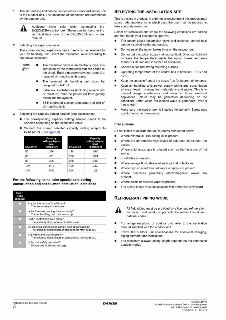
Cautions for selection of the air handling unit
Select the air handling unit (field supply) according to the technical data and limitations mentioned in Table 1.
Lifetime of the outdoor unit, operation range or operation reliability may be influenced if you neglect these limitations.
This control box can only be used in heat pump applications.
Depending on the heat exchanger, a connectable EKEXV (expansion valve kit) must be selected to these limitations.
Table 1
Quantity
Thermistor (R1T) 1
Thermistor (R3T/R2T) (2.5 m cable)
2
Insulation sheet 2
Rubber sheet 2
Wire to wire splice 6
Installation and operation manual
1
Screw nut 9
Tie wrap 6
Capacity setting adaptor 10
Stopper (closing cup) 1
EKEQMCBA
Expansion valve kit EKEXV
EKEQMCBA
Remote controller:- BRC1D528- BRC1E52- BRC2E52- BRC3E52
1
Parts and components
1 Outdoor unit
2 Control box
3 Air handling unit (field supply)
4 Field piping (field supply)
5 Expansion valve kit
Wiring connections
6 Outdoor unit power supply
7 Control box wiring(Power supply and communication between control box and outdoor unit)
8 Air handling unit thermistors
9 Power supply and control wiring for air handling unit and controller (power supply is separate from the outdoor unit)
10 Air thermistor control for air handling unit
11 Remote controller
Since design pressure is 4 MPa or 40 bar, pipes of larger wall thickness may be required. Refer to paragraph "Selection of piping material" on page 4.
NOTE For maximum number of indoor units, see the outdoor unit specifications.
If the total capacity of the connected indoor units exceeds the capacity of the outdoor unit, cooling and heating performance may drop when running the indoor units.Refer to the section on performance charac-teristics in the Engineering Data Book for details.
The capacity class of the air handling unit is determined by the selection of the expansion valve kit according to Table 1.
EKEXV class
Allowed heat exchanger cooling capacity (kW)
Allowed heat exchanger heating capacity (kW)
Minimum Maximum Minimum Maximum
50 5.0 6.2 5.6 7.0
63 6.3 7.8 7.1 8.8
80 7.9 9.9 8.9 11.1
100 10.0 12.3 11.2 13.8
125 12.4 15.4 13.9 17.3
140 15.5 17.6 17.4 19.8
200 17.7 24.6 19.9 27.7
250 24.7 30.8 27.8 34.7
400 35.4 49.5 39.8 55.0
500 49.6 61.6 55.1 69.3
Cooling saturated suction temperature (SST) = 6°C
Heating saturated suction temperature (SST) = 46°C
Air temperature = 27°C DB/19°C WB
Air temperature = 20°C DB
Superheat (SH) = 5 K Subcool (SC) = 3 K
EKEQMCBAV3Option kit for combination of Daikin condensing unitswith field-supplied air handling units4P383213-1B – 2016.10
Installation and operation manual
2
4PEN383213-1_2016_10.book Page 3 Tuesday, October 11, 2016 10:39 AM
1 The air handling unit can be connected as a standard indoor unit to the outdoor unit. The limitations of connection are determined by the outdoor unit.
2 Selecting the expansion valve
The corresponding expansion valve needs to be selected for your air handling unit. Select the expansion valve according to the above limitations.
3 Selecting the capacity setting adaptor (see accessories)
The corresponding capacity setting adaptor needs to be selected depending on the expansion valve.
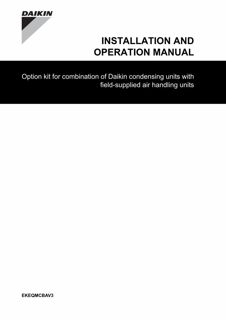
Connect the correct selected capacity setting adaptor to X24A (A1P). (See figure 3)
For the following items, take special care during construction and check after installation is finished
SELECTING THE INSTALLATION SITE
This is a class A product. In a domestic environment this product may cause radio interference in which case the user may be required to take adequate measures.
Select an installation site where the following conditions are fulfilled and that meets your customer’s approval.
The option boxes (expansion valve and electrical control box) can be installed inside and outside.
Do not install the option boxes in or on the outdoor unit.
Do not put the option boxes in direct sunlight. Direct sunlight will increase the temperature inside the option boxes and may reduce its lifetime and influence its operation.
Choose a flat and strong mounting surface.
Operating temperature of the control box is between –10°C and 40°C.
Keep the space in front of the boxes free for future maintenance.
Keep air handling unit, power supply wiring and transmission wiring at least 1 m away from televisions and radios. This is to prevent image interference and noise in those electrical appliances. (Noise may be generated depending on the conditions under which the electric wave is generated, even if 1 m is kept.)
Make sure the control box is installed horizontally. Screw nuts position must be downwards.
Precautions
Do not install or operate the unit in rooms mentioned below.
Where mineral oil, like cutting oil is present.
Where the air contains high levels of salt such as air near the ocean.
Where sulphurous gas is present such as that in areas of hot spring.
In vehicles or vessels.
Where voltage fluctuates a lot such as that in factories.
Where high concentration of vapor or spray are present.
Where machines generating electromagnetic waves are present.
Where acidic or alkaline vapor is present.
The option boxes must be installed with entrances downward.
REFRIGERANT PIPING WORK
For refrigerant piping of outdoor unit, refer to the installation manual supplied with the outdoor unit.
Follow the outdoor unit specifications for additional charging, piping diameter and installation.
The maximum allowed piping length depends on the connected outdoor model.
Additional limits exist when connecting the EKEQMCBA control box. These can be found in the technical data book of the EKEQMCBA and in this manual.
NOTE The expansion valve is an electronic type, it is controlled by the thermistors that are added in the circuit. Each expansion valve can control a range of air handling units sizes.
The selected air handling unit must be designed for R410A.
Extraneous substances (including mineral oils or moisture) must be prevented from getting mixed into the system.
SST: saturated suction temperature at exit of air handling unit.
EKEXV kit
Capacity setting adaptor
label (indication) EKEXV kit
Capacity setting adaptor
label (indication)
50 J56 140 J160
63 J71 200 J224
80 J90 250 J280
100 J112 400 J22
125 J140 500 J28
Tick when
checked
Are the thermistors fixed firmly?Thermistor may come loose.
Is the freeze-up setting done correctly?The air handling unit may freeze up.
Is the control box fixed firmly?The unit may drop, vibrate or make noise.
Do electrical connections comply with specifications?The unit may malfunction or components may burn out.
Are wiring and piping correct?The unit may malfunction or components may burn out.
Is the unit safely grounded?Dangerous at electric leakage.
All field piping must be provided by a licensed refrigeration technician and must comply with the relevant local and national codes.
Installation and operation manual
3EKEQMCBAV3
Option kit for combination of Daikin condensing unitswith field-supplied air handling units
4P383213-1B – 2016.10
4PEN383213-1_2016_10.book Page 4 Tuesday, October 11, 2016 10:39 AM
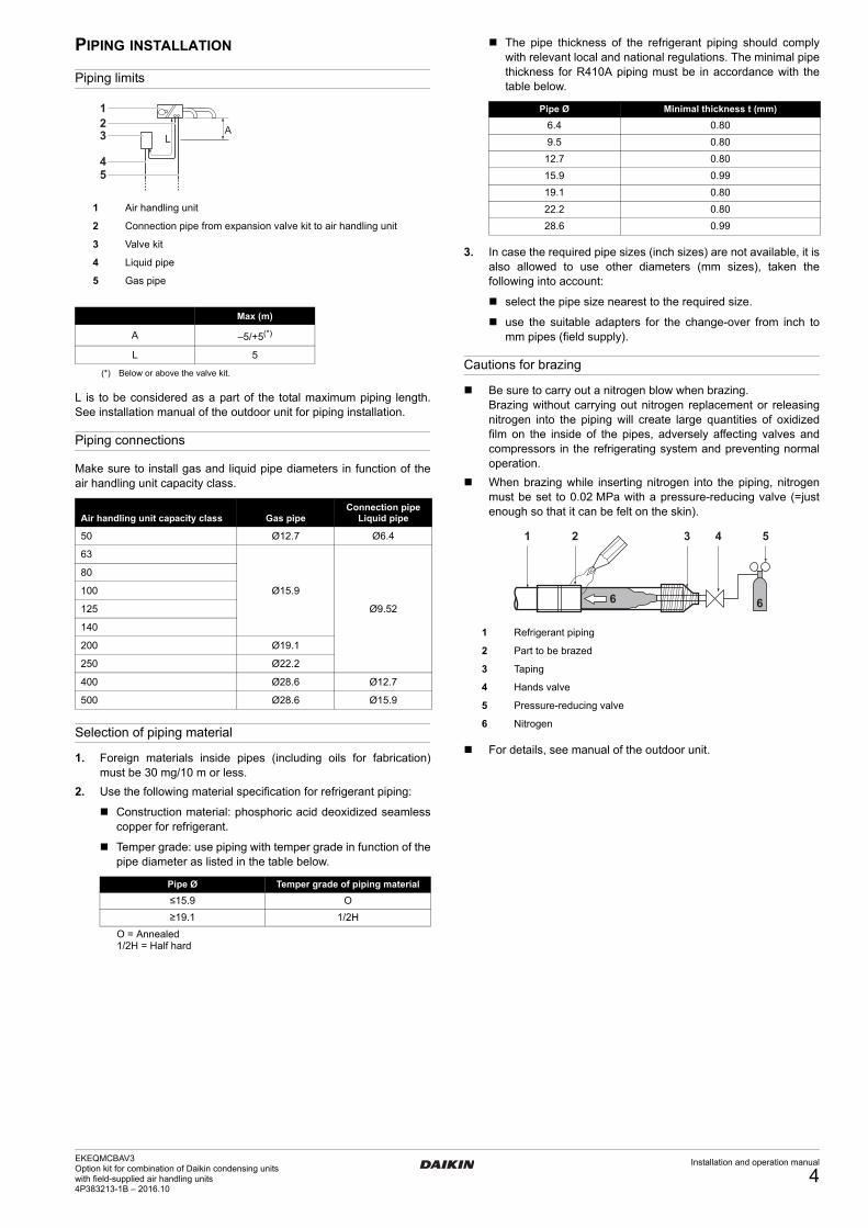
PIPING INSTALLATION
Piping limits
L is to be considered as a part of the total maximum piping length. See installation manual of the outdoor unit for piping installation.
Piping connections
Make sure to install gas and liquid pipe diameters in function of the air handling unit capacity class.
Selection of piping material
1. Foreign materials inside pipes (including oils for fabrication) must be 30 mg/10 m or less.
2. Use the following material specification for refrigerant piping:
Construction material: phosphoric acid deoxidized seamless copper for refrigerant.
Temper grade: use piping with temper grade in function of the pipe diameter as listed in the table below.
The pipe thickness of the refrigerant piping should comply with relevant local and national regulations. The minimal pipe thickness for R410A piping must be in accordance with the table below.
3. In case the required pipe sizes (inch sizes) are not available, it is also allowed to use other diameters (mm sizes), taken the following into account:
select the pipe size nearest to the required size.
use the suitable adapters for the change-over from inch to mm pipes (field supply).
Cautions for brazing
Be sure to carry out a nitrogen blow when brazing.Brazing without carrying out nitrogen replacement or releasing nitrogen into the piping will create large quantities of oxidized film on the inside of the pipes, adversely affecting valves and compressors in the refrigerating system and preventing normal operation.
When brazing while inserting nitrogen into the piping, nitrogen must be set to 0.02 MPa with a pressure-reducing valve (=just enough so that it can be felt on the skin).
For details, see manual of the outdoor unit.
1 Air handling unit
2 Connection pipe from expansion valve kit to air handling unit
3 Valve kit
4 Liquid pipe
5 Gas pipe
Max (m)
A –5/+5(*)
(*) Below or above the valve kit.
L 5
Air handling unit capacity class Gas pipeConnection pipe
Liquid pipe
50 Ø12.7 Ø6.4
63
Ø15.9
Ø9.52
80
100
125
140
200 Ø19.1
250 Ø22.2
400 Ø28.6 Ø12.7
500 Ø28.6 Ø15.9
Pipe Ø Temper grade of piping material
≤15.9 O
≥19.1 1/2H
O = Annealed 1/2H = Half hard
LA3
21
54
Pipe Ø Minimal thickness t (mm)
6.4 0.80
9.5 0.80
12.7 0.80
15.9 0.99
19.1 0.80
22.2 0.80
28.6 0.99
1 Refrigerant piping
2 Part to be brazed
3 Taping
4 Hands valve
5 Pressure-reducing valve
6 Nitrogen
1 2 3 4 5
66
EKEQMCBAV3Option kit for combination of Daikin condensing unitswith field-supplied air handling units4P383213-1B – 2016.10
Installation and operation manual
4
4PEN383213-1_2016_10.book Page 5 Tuesday, October 11, 2016 10:39 AM
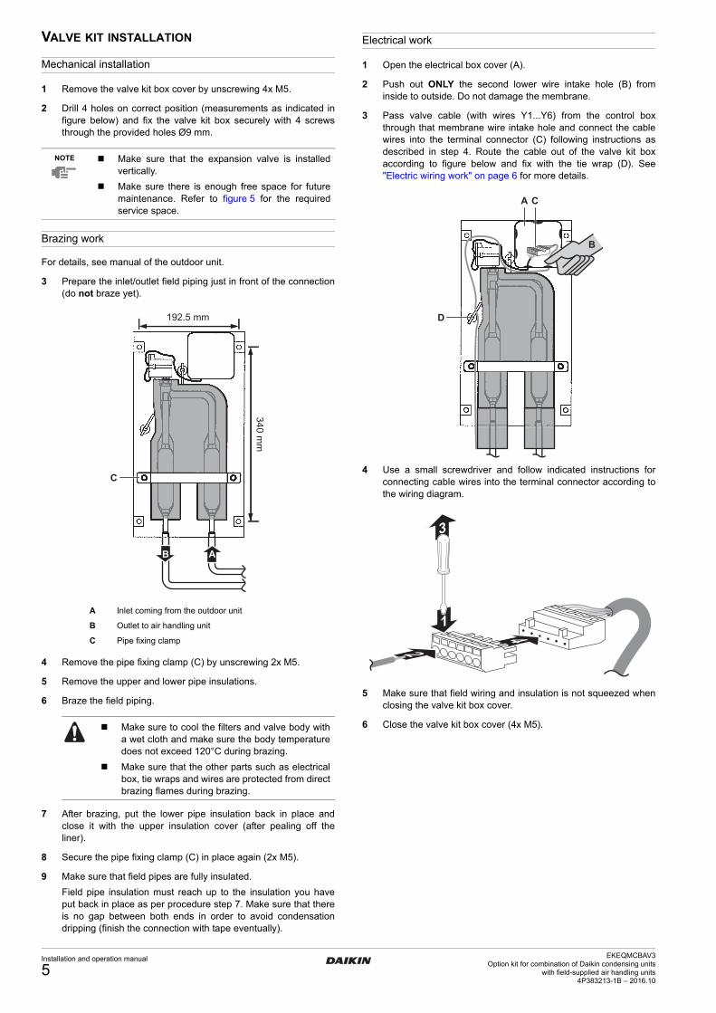
VALVE KIT INSTALLATION
Mechanical installation
1 Remove the valve kit box cover by unscrewing 4x M5.
2 Drill 4 holes on correct position (measurements as indicated in figure below) and fix the valve kit box securely with 4 screws through the provided holes Ø9 mm.
Brazing work
For details, see manual of the outdoor unit.
3 Prepare the inlet/outlet field piping just in front of the connection (do not braze yet).
4 Remove the pipe fixing clamp (C) by unscrewing 2x M5.
5 Remove the upper and lower pipe insulations.
6 Braze the field piping.
7 After brazing, put the lower pipe insulation back in place and close it with the upper insulation cover (after pealing off the liner).
8 Secure the pipe fixing clamp (C) in place again (2x M5).
9 Make sure that field pipes are fully insulated.
Field pipe insulation must reach up to the insulation you have put back in place as per procedure step 7. Make sure that there is no gap between both ends in order to avoid condensation dripping (finish the connection with tape eventually).
Electrical work
1 Open the electrical box cover (A).
2 Push out ONLY the second lower wire intake hole (B) from inside to outside. Do not damage the membrane.
3 Pass valve cable (with wires Y1...Y6) from the control box through that membrane wire intake hole and connect the cable wires into the terminal connector (C) following instructions as described in step 4. Route the cable out of the valve kit box according to figure below and fix with the tie wrap (D). See "Electric wiring work" on page 6 for more details.
4 Use a small screwdriver and follow indicated instructions for connecting cable wires into the terminal connector according to the wiring diagram.
5 Make sure that field wiring and insulation is not squeezed when closing the valve kit box cover.
6 Close the valve kit box cover (4x M5).
NOTE Make sure that the expansion valve is installed vertically.
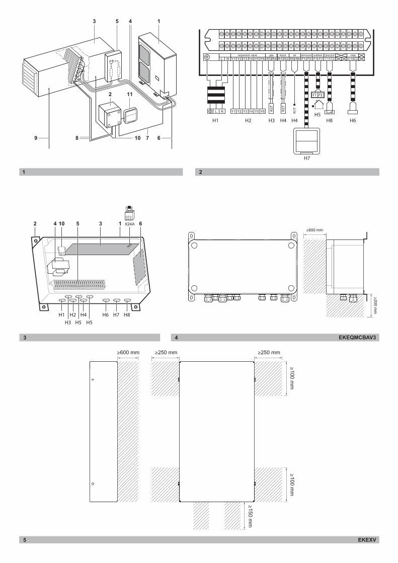
Make sure there is enough free space for future maintenance. Refer to figure 5 for the required service space.
A Inlet coming from the outdoor unit
B Outlet to air handling unit
C Pipe fixing clamp
Make sure to cool the filters and valve body with a wet cloth and make sure the body temperature does not exceed 120°C during brazing.
Make sure that the other parts such as electrical box, tie wraps and wires are protected from direct brazing flames during brazing.
192.5 mm
340 mm
C
B A
A C
D
B
41
2
3
Installation and operation manual
5EKEQMCBAV3
Option kit for combination of Daikin condensing unitswith field-supplied air handling units
4P383213-1B – 2016.10
4PEN383213-1_2016_10.book Page 6 Tuesday, October 11, 2016 10:39 AM
INSTALLATION OF THE ELECTRICAL CONTROL BOX (See figure 3)
Mechanical installation
1 Fix the control box with its hanger brackets to the mounting surface.
Use 4 screws (for holes of Ø6 mm).
2 Open the lid of the control box.
3 For electrical wiring: refer to paragraph "Electric wiring work" on page 6.
4 Install the screw nuts.
5 Close the unnecessary openings with stoppers (closing cups).
6 Close the lid securely after installation to ensure that the control box is watertight.
ELECTRIC WIRING WORK
All field wiring and components must be installed by a licensed electrician and must comply with all international, European, national and local directives, laws, regulations and/or codes that are relevant and applicable.
Use copper wire only.
A main switch or other means for disconnection, having a contact separation in all poles, must be incorporated in the fixed wiring in accordance with relevant local and national legislation.
Refer to the installation manual attached to the outdoor unit for the size of power supply electric wire connected to the outdoor unit, the capacity of the circuit breaker and switch, wiring and wiring instructions.
Attach the earth leakage circuit breaker and fuse to the power supply line.
Connection of the wires inside the control box
1 For connection to outdoor unit and to controller (field supply):
Pull the wires inside through the screw nut and close the nut firmly in order to ensure a good pull relieve and water protection.
2 The cables require an additional pull-relief. Strap the cable with the installed tie wrap.
Precautions
Thermistor cable and remote controller wire should be located at least 50 mm away from power supply wires and from wires to the controller. Not following this guideline may result in malfunction due to electrical noise.
Use only specified wires, and tightly connect wires to the terminals. Keep wiring in neat order so that it does not obstruct other equipment. Incomplete connections could result in overheating, and in worse case electric shock or fire.
1 Control box
2 Hanger brackets
3 Main PCB
4 Transformer
5 Terminal
6 Optional PCB (KRP4)
NOTE Make sure there is enough free space for future maintenance. Refer to figure 4 for the required service space.
EKEQMCBAV3Option kit for combination of Daikin condensing unitswith field-supplied air handling units4P383213-1B – 2016.10
Installation and operation manual
6

4PEN383213-1_2016_10.book Page 7 Tuesday, October 11, 2016 10:39 AM
Connecting the wiring: EKEQMCBAV3
Connect the wires to the terminal board according to the wiring diagram in figure 2. See figure 3 for wiring intake in the control box. The wiring intake hole indication H1 refers to the H1 cable of the corresponding wiring diagram. There are 2 wiring intake holes to allow for branching of the communication wire.
Connect cables according to specifications of the next table.
Table connection and application
Wiring diagram
A1P ....................Printed circuit board
A2P ....................Printed circuit board (option KRP4)
F1U ....................Fuse (250 V, F5A)(A1P)
F3U ....................Field fuse
HAP....................Light emitting diode (service monitor-green)
K1R ....................Magnetic relay
K4R ....................Magnetic relay (fan)
Q1DI...................Earth leakage breaker
R1T ....................Thermistor (air)
R2T ....................Thermistor (liquid)
R3T ....................Thermistor (gas)
R7.......................Capacity adaptor
T1R ....................Transformer (220 V/21.8 V)
X1M,X3M ...........Terminal block
Y1E ....................Electronic expansion valve
X1M-C1/C2 ........Output: fan ON/OFF
X1M-F1/F2 .........Communication outdoor unit
X1M-P1/P2.........Communication remote controller
X1M-R1/R2 ........Thermistor liquid
X1M-R3/R4 ........Thermistor gas
X1M-R5/R6 ........Thermistor air
X1M-T1/T2 ......... Input: ON/OFF
X1M-Y1~6 ..........Expansion valve
............Field wiring
L .........................Live
N.........................Neutral
, ..........Connector
.........................Wire clamp
......................Protective earth (screw)
...............Separate component
...............Optional accessory
BLK.....................Black
BLU ....................Blue
BRN....................Brown
GRN ...................Green
GRY....................Gray
ORG ...................Orange
PNK....................Pink
RED....................Red
WHT ...................White
YLW....................Yellow
Description Connect to Type of cableCross section
(mm2)(*)Maximum length
(m) Specifications
L, N, earth
Power supply Power supply H05VV-F3G2.5 2.5 — Power supply 230 V 1~ 50 Hz
Y1~Y6(†)
Expansion valve connection
Expansion valve kit LIYCY3 x 2 x 0.75
0.75
20 Digital output 12 V DC
R1,R2Thermistor R2T
(liquid pipe)
—
H05VV-F2 x 0.75
Standard: 2.5Max.: 20
Analog input 16 V DCR3,R4
Thermistor R3T(gas pipe)
R5,R6 Thermistor R1T (air)
P1,P2 Remote controller
100 Communication line 16 V DCF1,F2
Communication to outdoor unit
Outdoor unit
T1,T2 ON/OFF
Controller field supply
— Digital input 16 V DC
LIYCY4 x 2 x 0.75Optional connection: when the function of the switch box needs to be
extended: see KRP4A51 for details of settings and instructions.
— Capacity step
— Error signal
— Operation signal
C1,C2 Fan signalAir handling unit fan
field supplyH05VV-F3G2.5 2.5 —
Digital output: voltage free.Maximum 230 V, maximum 2 A
(*) Recommended size (all wiring must comply with local codes).(†) For EKEXV400 and 500, Y5 does not need to be connected.
Installation and operation manual
7EKEQMCBAV3
Option kit for combination of Daikin condensing unitswith field-supplied air handling units
4P383213-1B – 2016.10
4PEN383213-1_2016_10.book Page 8 Tuesday, October 11, 2016 10:39 AM
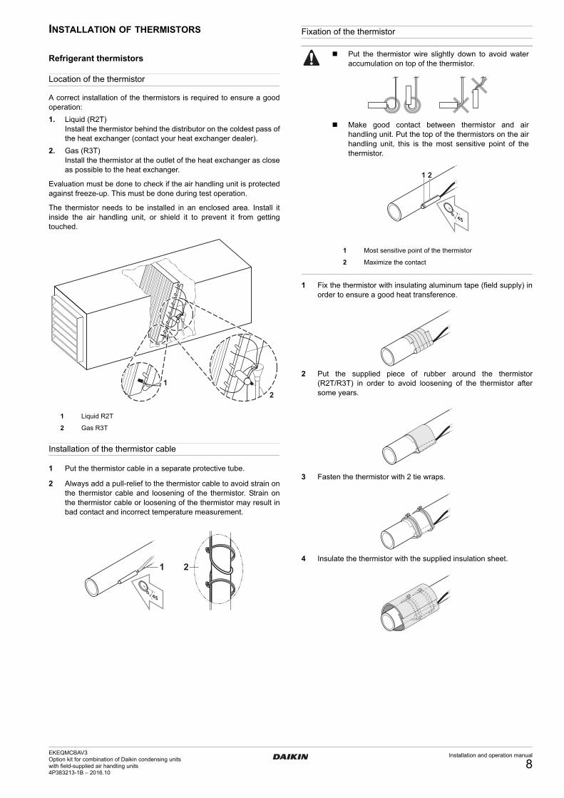
INSTALLATION OF THERMISTORS
Refrigerant thermistors
Location of the thermistor
A correct installation of the thermistors is required to ensure a good operation:
1. Liquid (R2T)Install the thermistor behind the distributor on the coldest pass of the heat exchanger (contact your heat exchanger dealer).
2. Gas (R3T)Install the thermistor at the outlet of the heat exchanger as close as possible to the heat exchanger.
Evaluation must be done to check if the air handling unit is protected against freeze-up. This must be done during test operation.
The thermistor needs to be installed in an enclosed area. Install it inside the air handling unit, or shield it to prevent it from getting touched.
Installation of the thermistor cable
1 Put the thermistor cable in a separate protective tube.
2 Always add a pull-relief to the thermistor cable to avoid strain on the thermistor cable and loosening of the thermistor. Strain on the thermistor cable or loosening of the thermistor may result in bad contact and incorrect temperature measurement.
Fixation of the thermistor
1 Fix the thermistor with insulating aluminum tape (field supply) in order to ensure a good heat transference.
2 Put the supplied piece of rubber around the thermistor (R2T/R3T) in order to avoid loosening of the thermistor after some years.
3 Fasten the thermistor with 2 tie wraps.
4 Insulate the thermistor with the supplied insulation sheet.
1 Liquid R2T
2 Gas R3T
12
1 2
45
Put the thermistor wire slightly down to avoid water accumulation on top of the thermistor.
Make good contact between thermistor and air handling unit. Put the top of the thermistors on the air handling unit, this is the most sensitive point of the thermistor.
21
45
1 Most sensitive point of the thermistor
2 Maximize the contact
EKEQMCBAV3Option kit for combination of Daikin condensing unitswith field-supplied air handling units4P383213-1B – 2016.10
Installation and operation manual
8
4PEN383213-1_2016_10.book Page 9 Tuesday, October 11, 2016 10:39 AM
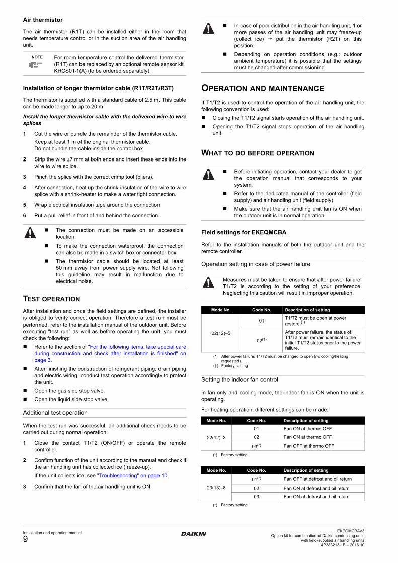
Air thermistor
The air thermistor (R1T) can be installed either in the room that needs temperature control or in the suction area of the air handling unit.
Installation of longer thermistor cable (R1T/R2T/R3T)
The thermistor is supplied with a standard cable of 2.5 m. This cable can be made longer to up to 20 m.
Install the longer thermistor cable with the delivered wire to wire splices
1 Cut the wire or bundle the remainder of the thermistor cable.
Keep at least 1 m of the original thermistor cable.Do not bundle the cable inside the control box.
2 Strip the wire ±7 mm at both ends and insert these ends into the wire to wire splice.
3 Pinch the splice with the correct crimp tool (pliers).
4 After connection, heat up the shrink-insulation of the wire to wire splice with a shrink-heater to make a water tight connection.
5 Wrap electrical insulation tape around the connection.
6 Put a pull-relief in front of and behind the connection.
TEST OPERATION
After installation and once the field settings are defined, the installer is obliged to verify correct operation. Therefore a test run must be performed, refer to the installation manual of the outdoor unit. Before executing "test run" as well as before operating the unit, you must check the following:
Refer to the section of "For the following items, take special care during construction and check after installation is finished" on page 3.
After finishing the construction of refrigerant piping, drain piping and electric wiring, conduct test operation accordingly to protect the unit.
Open the gas side stop valve.
Open the liquid side stop valve.
Additional test operation
When the test run was successful, an additional check needs to be carried out during normal operation.
1 Close the contact T1/T2 (ON/OFF) or operate the remote controller.
2 Confirm function of the unit according to the manual and check if the air handling unit has collected ice (freeze-up).
If the unit collects ice: see "Troubleshooting" on page 10.
3 Confirm that the fan of the air handling unit is ON.
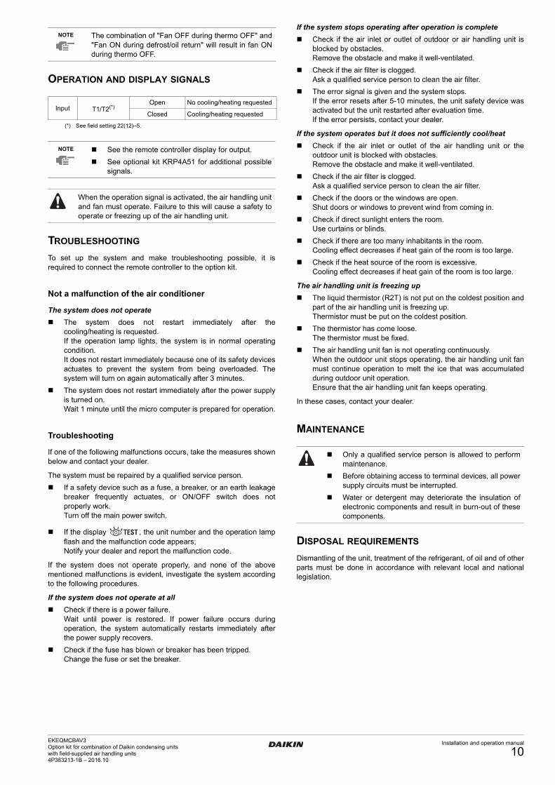
OPERATION AND MAINTENANCE
If T1/T2 is used to control the operation of the air handling unit, the following convention is used:
Closing the T1/T2 signal starts operation of the air handling unit.
Opening the T1/T2 signal stops operation of the air handling unit.
WHAT TO DO BEFORE OPERATION
Field settings for EKEQMCBA
Refer to the installation manuals of both the outdoor unit and the remote controller.
Operation setting in case of power failure
Setting the indoor fan control
In fan only and cooling mode, the indoor fan is ON when the unit is operating.
For heating operation, different settings can be made:
NOTE For room temperature control the delivered thermistor (R1T) can be replaced by an optional remote sensor kit KRCS01-1(A) (to be ordered separately).
The connection must be made on an accessible location.
To make the connection waterproof, the connection can also be made in a switch box or connector box.
The thermistor cable should be located at least 50 mm away from power supply wire. Not following this guideline may result in malfunction due to electrical noise.
In case of poor distribution in the air handling unit, 1 or more passes of the air handling unit may freeze-up (collect ice) put the thermistor (R2T) on this position.
Depending on operation conditions (e.g.: outdoor ambient temperature) it is possible that the settings must be changed after commissioning.
Before initiating operation, contact your dealer to get the operation manual that corresponds to your system.
Refer to the dedicated manual of the controller (field supply) and air handling unit (field supply).
Make sure that the air handling unit fan is ON when the outdoor unit is in normal operation.
Measures must be taken to ensure that after power failure, T1/T2 is according to the setting of your preference. Neglecting this caution will result in improper operation.
Mode No. Code No. Description of setting
22(12)–5
01T1/T2 must be open at power restore.(*)
(*) After power failure, T1/T2 must be changed to open (no cooling/heating requested).
02(†)
(†) Factory setting
After power failure, the status of T1/T2 must remain identical to the initial T1/T2 status prior to the power failure.
Mode No. Code No. Description of setting
22(12)–3
01 Fan ON at thermo OFF
02 Fan ON at thermo OFF
03(*)
(*) Factory setting
Fan OFF at thermo OFF
Mode No. Code No. Description of setting
23(13)–8
01(*)
(*) Factory setting
Fan OFF at defrost and oil return
02 Fan ON at defrost and oil return
03 Fan ON at defrost and oil return
Installation and operation manual
9EKEQMCBAV3
Option kit for combination of Daikin condensing unitswith field-supplied air handling units
4P383213-1B – 2016.10
4PEN383213-1_2016_10.book Page 10 Tuesday, October 11, 2016 10:39 AM
OPERATION AND DISPLAY SIGNALS
TROUBLESHOOTING
To set up the system and make troubleshooting possible, it is required to connect the remote controller to the option kit.
Not a malfunction of the air conditioner
The system does not operate
The system does not restart immediately after the cooling/heating is requested.If the operation lamp lights, the system is in normal operating condition.It does not restart immediately because one of its safety devices actuates to prevent the system from being overloaded. The system will turn on again automatically after 3 minutes.
The system does not restart immediately after the power supply is turned on.Wait 1 minute until the micro computer is prepared for operation.
Troubleshooting
If one of the following malfunctions occurs, take the measures shown below and contact your dealer.
The system must be repaired by a qualified service person.
If a safety device such as a fuse, a breaker, or an earth leakage breaker frequently actuates, or ON/OFF switch does not properly work.Turn off the main power switch.
If the display , the unit number and the operation lamp flash and the malfunction code appears;Notify your dealer and report the malfunction code.
If the system does not operate properly, and none of the above mentioned malfunctions is evident, investigate the system according to the following procedures.
If the system does not operate at all
Check if there is a power failure.Wait until power is restored. If power failure occurs during operation, the system automatically restarts immediately after the power supply recovers.
Check if the fuse has blown or breaker has been tripped.Change the fuse or set the breaker.
If the system stops operating after operation is complete
Check if the air inlet or outlet of outdoor or air handling unit is blocked by obstacles.Remove the obstacle and make it well-ventilated.
Check if the air filter is clogged.Ask a qualified service person to clean the air filter.
The error signal is given and the system stops.If the error resets after 5-10 minutes, the unit safety device was activated but the unit restarted after evaluation time.If the error persists, contact your dealer.
If the system operates but it does not sufficiently cool/heat
Check if the air inlet or outlet of the air handling unit or the outdoor unit is blocked with obstacles.Remove the obstacle and make it well-ventilated.
Check if the air filter is clogged.Ask a qualified service person to clean the air filter.
Check if the doors or the windows are open.Shut doors or windows to prevent wind from coming in.
Check if direct sunlight enters the room.Use curtains or blinds.
Check if there are too many inhabitants in the room.Cooling effect decreases if heat gain of the room is too large.
Check if the heat source of the room is excessive.Cooling effect decreases if heat gain of the room is too large.
The air handling unit is freezing up
The liquid thermistor (R2T) is not put on the coldest position and part of the air handling unit is freezing up.Thermistor must be put on the coldest position.
The thermistor has come loose.The thermistor must be fixed.
The air handling unit fan is not operating continuously.When the outdoor unit stops operating, the air handling unit fan must continue operation to melt the ice that was accumulated during outdoor unit operation.Ensure that the air handling unit fan keeps operating.
In these cases, contact your dealer.
MAINTENANCE
DISPOSAL REQUIREMENTS
Dismantling of the unit, treatment of the refrigerant, of oil and of other parts must be done in accordance with relevant local and national legislation.
NOTE The combination of "Fan OFF during thermo OFF" and "Fan ON during defrost/oil return" will result in fan ON during thermo OFF.
Input T1/T2(*)
(*) See field setting 22(12)–5.
Open No cooling/heating requested
Closed Cooling/heating requested
NOTE See the remote controller display for output.
See optional kit KRP4A51 for additional possible signals.
When the operation signal is activated, the air handling unit and fan must operate. Failure to this will cause a safety to operate or freezing up of the air handling unit.
Only a qualified service person is allowed to perform maintenance.
Before obtaining access to terminal devices, all power supply circuits must be interrupted.
Water or detergent may deteriorate the insulation of electronic components and result in burn-out of these components.
EKEQMCBAV3Option kit for combination of Daikin condensing unitswith field-supplied air handling units4P383213-1B – 2016.10
Installation and operation manual
10

4PEN383213-1_2016_10.book Page 1 Tuesday, October 11, 2016 10:39 AM

4PEN383213-1_2016_10.book Page 2 Tuesday, October 11, 2016 10:39 AM
4P383213-1B 2016.10
Cop
yrig
ht 2
014
Dai
kin
*4P383213-1 B 0000000Y*
4PEN383213-1_2016_10.book Page 1 Tuesday, October 11, 2016 10:39 AM