Embed Size (px)
Citation preview
Installation and Operation Manual
Part # H004595Rev. 10August 2017
Power over Ethernet (PoE) Clocks
© American Time2
PoE Installation ManualSafety Precautions
All electrical power wiring connected to the Power over Ethernet Clocks must be installed by qualified persons in conformance with applicable national and local electrical codes. Improper installation of this equipment can result in electrical shock and fire.
The PoE clock should be installed in a secure location protected from:
—Physical damage
—Water, including condensation
Operation of this product in a manner inconsistent with the instructions in the manual may result in personal injury and damage to the product and will void the warranty.
American Time140 3rd Street South, PO Box 707
Dassel, MN 55325-0707
Phone: 800-328-8996 Fax: 800-789-1882american-time.com

3© American Time
PoE Installation Manual Table of Contents
Introduction .......................................................................................................................................................................... 4Specifications ....................................................................................................................................................................... 5 Analog Clocks ............................................................................................................................................................ 5 Digital Clocks ............................................................................................................................................................ 6 Relay ......................................................................................................................................................................... 7Installation ........................................................................................................................................................................... 8 Analog Clocks ............................................................................................................................................................ 8 Digital Clocks ............................................................................................................................................................ 9 Relay ....................................................................................................................................................................... 12Network Clock Connect...................................................................................................................................................... 14 System Requirements .............................................................................................................................................. 14 Installation ............................................................................................................................................................... 14 Login ....................................................................................................................................................................... 14 Main Screen ............................................................................................................................................................ 15 Configuration ........................................................................................................................................................... 17 Clock Tab .......................................................................................................................................................... 17 Time Zone Tab .................................................................................................................................................. 18 DST Tab ............................................................................................................................................................ 18 Network Tab ..................................................................................................................................................... 19 Buzzer Tab ........................................................................................................................................................ 20 Manuf Tab ......................................................................................................................................................... 20 Schedule Editor ................................................................................................................................................. 21 Event Editor ....................................................................................................................................................... 22 Web Browser Interface ...................................................................................................................................... 23 Network ................................................................................................................................................... 23 Time Synchronization ............................................................................................................................... 24 Daylight Saving Time ................................................................................................................................ 24 Other Configurations ................................................................................................................................ 25Troubleshooting: DHCP ....................................................................................................................................................... 26Troubleshooting: Clock Time ............................................................................................................................................. 28Appendix A: NIST Time Servers .........................................................................................................................................29Appendix B: Supported Time Zones ..................................................................................................................................29Appendix C: Buzzer/Relay Scheduling Examples..............................................................................................................30Appendix D: Brightness Control Scheduling Example ...................................................................................................... 32
© American Time4
PoE Installation ManualA
pp
en
dix
Trou
ble
shooti
ng
Con
figur
atio
nN
etw
ork
Clo
ck
Connect
Inst
alla
tion
Intr
oducti
on
Specifi
cati
ons
Introduction
Power over Ethernet (PoE) provides an accurate synchronized time source. PoE and Simple Network Time Protocol (SNTP) are used to make installation and setup as simple as possible. All you need to do is connect the clock to a PoE enabled Local Area Network (LAN) Ethernet drop.
PoEPower over Ethernet (PoE) describes a system that passes electrical power, along with data, on Ethernet cabling. Power may come from a power supply within a networking device such as a PoE switch or it may be injected into the Ethernet cable using a midspan injector.
There are several advantages for using PoE. PoE eliminates the need to run AC power cables for certain devices. Instead, the more cost effective category 5 or 6 cable is run for PoE devices. Also, since PoE is symmetrically distributed, the power source may be determined after the cables are ran.
PoE clocks require connection to a PoE enabled LAN. In a typical installation, a PoE switch or a PoE injector would be used to power your PoE clock.
NetworkThese Power over Ethernet Clocks are plug and play on networks with Dynamic Hosting Configuration Protocol (DHCP). A NIST time server is used for the default time server but may be changed using the Network Clock Connect application or the configuration web page.
The clocks may also be configured using static IP addresses.
5© American Time
PoE Installation Manual Specifications
Power over Ethernet Analog ClocksAvailable in the following configurations:PEXXXXXXXXB – Buzzer versionPEXXXXXXXX – Analog VersionNote: The X's are model dependent
Optional Products:PoE Injector, single port – TMA200USB Drive with Network Clock Connect Software – H004167B-POESecurity Bracket (part number varies by size)
Features• Time Zone Management• Supports up to 10 SNTP servers for redundancy• Supports Daylight Saving Time• Power over Ethernet (IEEE802.3af)• DHCP or Static IP addressing• Network Clock Connect configuration• Status LED indicator• Scheduling (Buzzer version) - maximum of 100 scheduled events
SpecificationsDimensions: Varies by modelWeight: Varies by modelPower Consumption: PoE, IEEE802.3af compliant, 1WOperating Temperature: 32˚F to 104˚F (0˚ to 40˚C)Operating Humidity: 95% maximum, non-condensingAccuracy: ±1 second
Buzzer Option SpecificationsSound Level: 65dBA at 10 feet
© American Time6
PoE Installation Manual
Power over Ethernet Digital/Calendar Clocks Available in the following configurations:POEXXXXSXEPOEXXXXSEB - Buzzer versionPOEXMXXSE - Calendar versionPOEXMXXSEB - Calendar buzzer versionNote: The X's are model dependent
Optional Products:PoE Injector, single port – TMA200USB Drive with Network Clock Connect Software – H004167B-POEDouble Dial Kit (part number varies by size)
Features• Time Zone Management• Supports up to 10 SNTP servers for redundancy• Supports Daylight Saving Time• 12/24 Hour Mode with AM/PM indicators• Power over Ethernet (IEEE802.3af)• DHCP or Static IP addressing• Network Clock Connect configuration• Programmable Brightness Controls (High, Low, Sleep, Off)• Countdown Timer• Scheduling (Buzzer/Relay) - maximum of 100 scheduled events• Calendar Clock Display Modes: -MM:DD:YY -DD:MM:YY -YY:MM:DD -M:D:YY -D:M:YY -YY:M:D• Configurable date/time toggle durations
SpecificationsDimensions: 2.5" display: 4 & 6 digit - 141/8" x 41/8" x 23/8"d 4" display: 4 digit - 171/2" x 61/4" x 21/2"d 4" display: 6 digit - 257/8" x 63/16" x 21/2"dWeight: Varies by modelPower Consumption: PoE, IEEE 802.3af compliant
Operating Temperature: 32˚F to 104˚F (0˚ to 40˚C)Operating Humidity: 95% maximum, non-condensingAccuracy: ±1 second
Buzzer Option SpecificationsSound Level: 65dBA at 10 feet
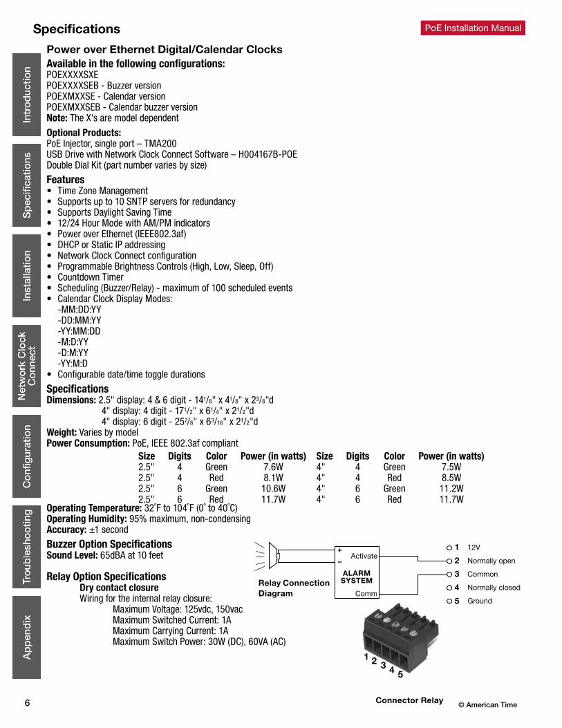
Relay Option Specifications Dry contact closure Wiring for the internal relay closure: Maximum Voltage: 125vdc, 150vac Maximum Switched Current: 1A Maximum Carrying Current: 1A Maximum Switch Power: 30W (DC), 60VA (AC)
1 2 3 4 5
1
2
3
4
5
Normally open
Common
Ground
Normally closed
12VActivate
+
–
ALARMSYSTEM
Comm
Specifications
Relay ConnectionDiagram
Connector Relay
Size Digits Color Power (in watts)2.5" 4 Green 7.6W2.5" 4 Red 8.1W2.5" 6 Green 10.6W2.5" 6 Red 11.7W
Size Digits Color Power (in watts)4" 4 Green 7.5W4" 4 Red 8.5W4" 6 Green 11.2W4" 6 Red 11.7W
7© American Time
PoE Installation Manual
12
Specifications
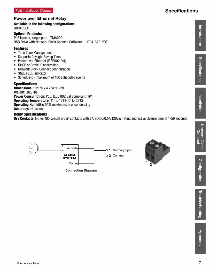
Power over Ethernet RelayAvailable in the following configurations:H004896R
Optional Products:PoE Injector, single port – TMA200USB Drive with Network Clock Connect Software – H004167B-POE
Features• Time Zone Management• Supports Daylight Saving Time• Power over Ethernet (IEEE802.3af)• DHCP or Static IP addressing• Network Clock Connect configuration• Status LED indicator• Scheduling - maximum of 100 scheduled events
SpecificationsDimensions: 2.21"h x 4.2"w x .9"dWeight: .028 lbs.Power Consumption: PoE, IEEE 802.3af compliant, 1WOperating Temperature: 41˚ to 131˚F (0˚ to 55˚C)Operating Humidity: 95% maximum, non-condensingAccuracy: ±1 second
Relay SpecificationsDry Contacts: NO (or NC-special order) contacts with 2A 30vdc/0.5A 120vac rating and active closure time of 1-59 seconds
1
2
Normally open
Common
Activate+
–
ALARMSYSTEM
Comm
Connection Diagram
© American Time8
PoE Installation ManualAnalog Clock Installation
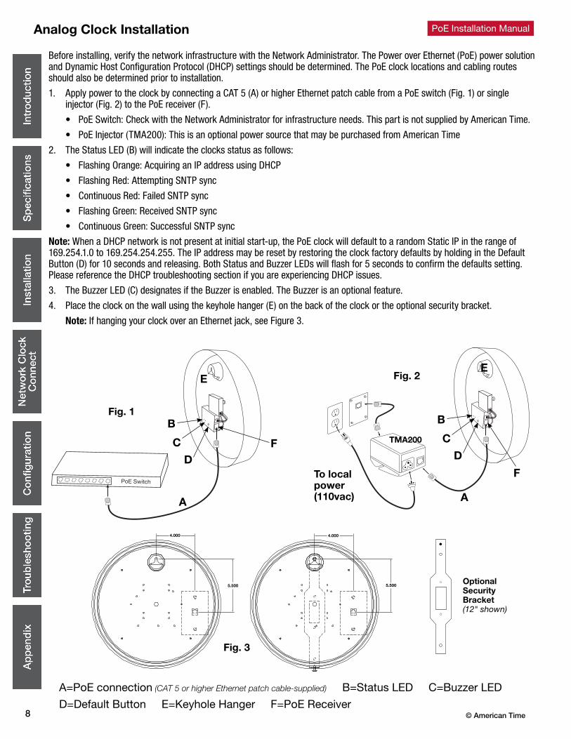
Before installing, verify the network infrastructure with the Network Administrator. The Power over Ethernet (PoE) power solution and Dynamic Host Configuration Protocol (DHCP) settings should be determined. The PoE clock locations and cabling routes should also be determined prior to installation.
1. Apply power to the clock by connecting a CAT 5 (A) or higher Ethernet patch cable from a PoE switch (Fig. 1) or single injector (Fig. 2) to the PoE receiver (F).
• PoE Switch: Check with the Network Administrator for infrastructure needs. This part is not supplied by American Time.
• PoE Injector (TMA200): This is an optional power source that may be purchased from American Time
2. The Status LED (B) will indicate the clocks status as follows:
• Flashing Orange: Acquiring an IP address using DHCP
• Flashing Red: Attempting SNTP sync
• Continuous Red: Failed SNTP sync
• Flashing Green: Received SNTP sync
• Continuous Green: Successful SNTP sync
Note: When a DHCP network is not present at initial start-up, the PoE clock will default to a random Static IP in the range of 169.254.1.0 to 169.254.254.255. The IP address may be reset by restoring the clock factory defaults by holding in the Default Button (D) for 10 seconds and releasing. Both Status and Buzzer LEDs will flash for 5 seconds to confirm the defaults setting. Please reference the DHCP troubleshooting section if you are experiencing DHCP issues.
3. The Buzzer LED (C) designates if the Buzzer is enabled. The Buzzer is an optional feature.
4. Place the clock on the wall using the keyhole hanger (E) on the back of the clock or the optional security bracket.
Note: If hanging your clock over an Ethernet jack, see Figure 3.
A=PoE connection (CAT 5 or higher Ethernet patch cable-supplied) B=Status LED C=Buzzer LED
D=Default Button E=Keyhole Hanger F=PoE Receiver
A
B
D
E
C
Fig. 1
F
reset
AC
DC
To wiring box
Optional SecurityBracket(12" shown)
To local power(110vac)
EFig. 2
A
TMA200
Fig. 3
B
D
C
F

9© American Time
PoE Installation Manual Digital Clock Installation
Before installing, verify the network infrastructure with the Network Administrator. The Power over Ethernet (PoE) power solution and Dynamic Host Configuration Protocol (DHCP) settings should be determined. The PoE clock locations and cabling routes should also be determined prior to installation.
1. Apply power to the clock by connecting a CAT 5 (A) or higher Ethernet patch cable from a PoE switch (Fig. 1) or single injector (Fig. 2) to the rear panel of the PoE clock. The time should display in less than one minute.
• PoE Switch: Check with the Network Administrator for infrastructure needs. This part is not supplied by American Time.
• PoE Injector (TMA200): This is an optional power source that may be purchased from American Time
Note: When a DHCP network is not present at initial start-up, the PoE clock will default to a random Static IP in the range of 169.254.1.0 to 169.254.254.255.
If DHCP is enabled and the clock does not receive a DHCP IP or loses the IP, the following symptoms will occur:
– For 6 digit clocks, the seconds digits on the far right hand side of the clock will flash. – For 4 digit clocks, the AM/PM indicators on the left side of the clock will flash
2. Upon startup the clock Firmware version and IP address will scroll across the display.
3. To adjust the Time Zone, push the Set button (B). Each button push will adjust the time by -1 hour. Example: If set to Central Standard Time, push the button once for Mountain Standard Time.
4. Place the clock on the wall using the keyhole hanger (C) on the back of the clock. A mounting template is included with the Quick Start Installation Guide.
Default Settings can be restored to the clock by: 1. Remove power to the clock for at least 2 seconds (disconnect the patch cable (A) from the back of the clock). 2. Hold down the Set button (B) on the back of the clock. 3. Apply power back to the clock (connect the powered patch cable to the clock) while continuing to hold down the Set button. 4. 888 should scroll across the clock display. 5. Release the Set button.
Note: The IP address set to the clock can be checked by quickly pressing the Set button (B) twice. The Set button is located on the back of the clock next to the patch cable (A) plug-in. Once pressed the clock IP address will scroll quickly across the display.
A=PoE connection (CAT 5 or higher Ethernet patch cable-supplied) B=Set Button C=Keyhole hanger D=Relay
A
B CCFig. 1 D
Fig. 2
CCB
A
To local power(110vac)
TMA200
D
© American Time10
PoE Installation ManualDigital Clock Installation
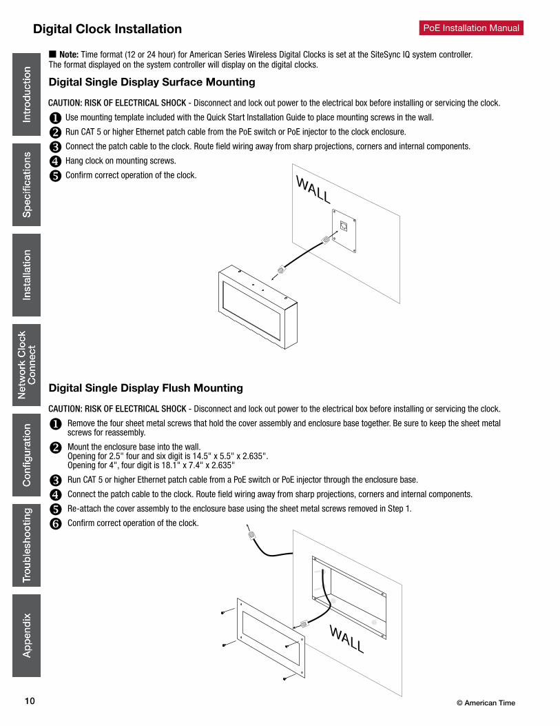
CAUTION: RISK OF ELECTRICAL SHOCK - Disconnect and lock out power to the electrical box before installing or servicing the clock.
u Use mounting template included with the Quick Start Installation Guide to place mounting screws in the wall.
v Run CAT 5 or higher Ethernet patch cable from the PoE switch or PoE injector to the clock enclosure.
w Connect the patch cable to the clock. Route field wiring away from sharp projections, corners and internal components.
x Hang clock on mounting screws.
y Confirm correct operation of the clock.
Digital Single Display Surface Mounting
Digital Single Display Flush Mounting
CAUTION: RISK OF ELECTRICAL SHOCK - Disconnect and lock out power to the electrical box before installing or servicing the clock.
u Remove the four sheet metal screws that hold the cover assembly and enclosure base together. Be sure to keep the sheet metal screws for reassembly.
v Mount the enclosure base into the wall. Opening for 2.5" four and six digit is 14.5" x 5.5" x 2.635". Opening for 4", four digit is 18.1" x 7.4" x 2.635"
w Run CAT 5 or higher Ethernet patch cable from a PoE switch or PoE injector through the enclosure base.
x Connect the patch cable to the clock. Route field wiring away from sharp projections, corners and internal components.
yRe-attach the cover assembly to the enclosure base using the sheet metal screws removed in Step 1.
z Confirm correct operation of the clock.
n Note: Time format (12 or 24 hour) for American Series Wireless Digital Clocks is set at the SiteSync IQ system controller. The format displayed on the system controller will display on the digital clocks.

11© American Time
PoE Installation Manual Digital Clock Installation
Digital Double Face Display Mounting
CAUTION: RISK OF ELECTRICAL SHOCK - Disconnect and lock out power to the electrical box before installing or servicing the clock.
u For wall mount, assemble double dial clock enclosure as shown in Figure 1. For ceiling mount, use the same assembly procedure, except use the two knockouts that are located on the top of the wraparound (see Figure 2).
v Depending on the orientation of the 4" square backbox, use two #8-32 x 3/4" screws and two #8-32 nuts for the two dummy holes in the mounting plate.
w Run patch cable through the conduit.
x Using two #8-32 x 3/4" screws, mount double dial clock enclosure assembly to 4" square backbox (see Figure 2).
y Loosen the eight screws in the digital clock approximately 3/32" (see Figure 2)
z Make patch cable connection to the digital clock.
Slide the digital clock into the wraparound making sure the screws and slots line up (see Figure 2), then tighten the eight screws securely.
Repeat steps 5 through 7 for the second clock
Slots
Screws
4 square backbox(not supplied)
Wraparound
Digital clock
Digital clock
Knockouts for ceiling mount
WALL
Wraparound
Plate Bushing
LocknutConduitFigure 1
Figure 2
© American Time12
PoE Installation ManualRelay Installation
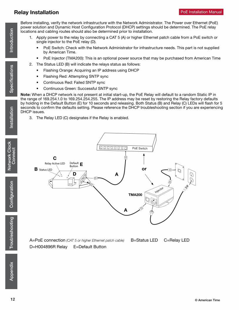
Before installing, verify the network infrastructure with the Network Administrator. The Power over Ethernet (PoE) power solution and Dynamic Host Configuration Protocol (DHCP) settings should be determined. The PoE relay locations and cabling routes should also be determined prior to installation.
1. Apply power to the relay by connecting a CAT 5 (A) or higher Ethernet patch cable from a PoE switch or single injector to the PoE relay (D).
• PoE Switch: Check with the Network Administrator for infrastructure needs. This part is not supplied by American Time.
• PoE Injector (TMA200): This is an optional power source that may be purchased from American Time
2. The Status LED (B) will indicate the relays status as follows:
• Flashing Orange: Acquiring an IP address using DHCP
• Flashing Red: Attempting SNTP sync
• Continuous Red: Failed SNTP sync
• Continuous Green: Successful SNTP sync
Note: When a DHCP network is not present at initial start-up, the PoE Relay will default to a random Static IP in the range of 169.254.1.0 to 169.254.254.255. The IP address may be reset by restoring the Relay factory defaults by holding in the Default Button (E) for 10 seconds and releasing. Both Status (B) and Relay (C) LEDs will flash for 5 seconds to confirm the defaults setting. Please reference the DHCP troubleshooting section if you are experiencing DHCP issues.
3. The Relay LED (C) designates if the Relay is enabled.
A=PoE connection (CAT 5 or higher Ethernet patch cable) B=Status LED C=Relay LED
D=H004896R Relay E=Default Button
Status LED
Relay Active LED DefaultButton
Injector
E
AB
C
D
A
or
TMA200
13© American Time
PoE Installation Manual User Notes

© American Time14
PoE Installation ManualNetwork Clock Connect
Network Clock Connect has been developed by American Time for configuring and monitoring your network clocks. This application will allow the user to quickly manage all of the compatible network clocks installed on the network.
System Requirements
Personal Computers:
Windows 7 - 32-bit Windows 8
Windows 7 - 64-bit Windows 10
PC with 500Mhz or higher processor clock speed recommended
50MB free storage
256MB or RAM or higher recommended
VGA (800x600) or higher-resolution video adapter and monitor
Keyboard and Mouse
Installation
1. Network Clock Connect may be downloaded from, http://www.american-time.com/support/product-documentation. Click Search Now and click on Network Clock Connect from the list. The software will automatically download. It is also provided through the optional USB drive (H004167B-POE-sold separately).
2. Run the Windows Installer Package, NCCSetup.msi, file by double-clicking the icon:
3. Follow the instructions in the Network Clock Connect Setup Wizard.
Login – Default Password clock4u
1. Double-click on the Network Clock Connect desktop icon to start the application.
2. Enter clock4u in the password prompt and press OK.
15© American Time
PoE Installation Manual
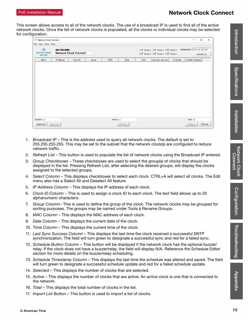
This screen allows access to all of the network clocks. The use of a broadcast IP is used to find all of the active network clocks. Once the list of network clocks is populated, all the clocks or individual clocks may be selected for configuration.
1. Broadcast IP – This is the address used to query all network clocks. The default is set to 255.255.255.255. This may be set to the subnet that the network clock(s) are configured to reduce network traffic.
2. Refresh List – This button is used to populate the list of network clocks using the Broadcast IP entered.
3. Group Checkboxes – These checkboxes are used to select the group(s) of clocks that should be displayed in the list. Pressing Refresh List, after selecting the desired groups, will display the clocks assigned to the selected groups.
4. Select Column – This displays checkboxes to select each clock. CTRL+A will select all clocks. The Edit menu also has a Select All and Deselect All feature.
5. IP Address Column – This displays the IP address of each clock.
6. Clock ID Column – This is used to assign a clock ID to each clock. The text field allows up to 20 alphanumeric characters.
7. Group Column– This is used to define the group of the clock. The network clocks may be grouped for sorting purposes. The groups may be named under Tools à Rename Groups.
8. MAC Column – This displays the MAC address of each clock.
9. Date Column – This displays the current date of the clock.
10. Time Column – This displays the current time of the clock.
11. Last Sync Success Column – This displays the last time the clock received a successful SNTP synchronization. The field will turn green to designate a successful sync and red for a failed sync.
12. Schedule Button Column – This button will be displayed if the network clock has the optional buzzer/relay. If the clock does not have a buzzer/relay, the field will display N/A. Reference the Schedule Editor section for more details on the buzzer/relay scheduling.
13. Schedule Timestamp Column – This displays the last time the schedule was altered and saved. The field will turn green to designate a successful schedule update and red for a failed schedule update.
14. Selected – This displays the number of clocks that are selected.
15. Active – This displays the number of clocks that are active. An active clock is one that is connected to the network.
16. Total – This displays the total number of clocks in the list.
17. Import List Button – This button is used to import a list of clocks.
Network Clock Connect

© American Time16
PoE Installation ManualNetwork Clock Connect
18. Export List Button – This button is used to export a list of clocks. This button cannot be pressed if no clocks are selected.
• This is useful for saving the network clock list for future reference to identify clocks that may become nonresponsive.
19. SNTP Sync Button – This button is used to synchronize the selected clocks to the configured SNTP server. The selected clocks Last Sync Success fields will change red when this button is pressed. Once the clocks obtain the SNTP sync, the Last Sync Success field will update to green with the correct date and time.
20. Configure Button – This is used to enter the Configuration Menu for the selected clocks. Reference the Configuration section for more details.
21. Print List Button – This button is used to print the list of clocks.
22. Help Menu – This menu contains a shortcut to the American Time PoE clock support site. Manuals, firmware/software updates, and tutorials are contained on the support site.
17© American Time
PoE Installation Manual Configuration
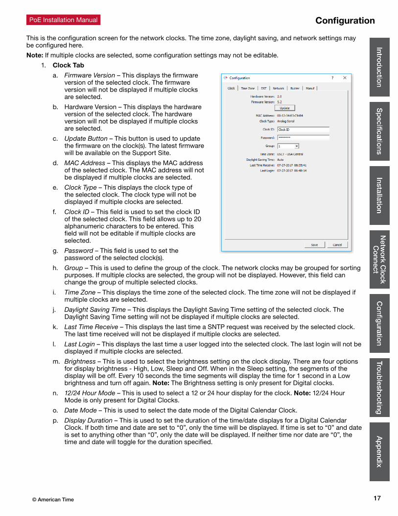
This is the configuration screen for the network clocks. The time zone, daylight saving, and network settings may be configured here.
Note: If multiple clocks are selected, some configuration settings may not be editable.
1. Clock Tab
a. Firmware Version – This displays the firmware version of the selected clock. The firmware version will not be displayed if multiple clocks are selected.
b. Hardware Version – This displays the hardware version of the selected clock. The hardware version will not be displayed if multiple clocks are selected.
c. Update Button – This button is used to update the firmware on the clock(s). The latest firmware will be available on the Support Site.
d. MAC Address – This displays the MAC address of the selected clock. The MAC address will not be displayed if multiple clocks are selected.
e. Clock Type – This displays the clock type of the selected clock. The clock type will not be displayed if multiple clocks are selected.
f. Clock ID – This field is used to set the clock ID of the selected clock. This field allows up to 20 alphanumeric characters to be entered. This field will not be editable if multiple clocks are selected.
g. Password – This field is used to set the password of the selected clock(s).
h. Group – This is used to define the group of the clock. The network clocks may be grouped for sorting purposes. If multiple clocks are selected, the group will not be displayed. However, this field can change the group of multiple selected clocks.
i. Time Zone – This displays the time zone of the selected clock. The time zone will not be displayed if multiple clocks are selected.
j. Daylight Saving Time – This displays the Daylight Saving Time setting of the selected clock. The Daylight Saving Time setting will not be displayed if multiple clocks are selected.
k. Last Time Receive – This displays the last time a SNTP request was received by the selected clock. The last time received will not be displayed if multiple clocks are selected.
l. Last Login – This displays the last time a user logged into the selected clock. The last login will not be displayed if multiple clocks are selected.
m. Brightness – This is used to select the brightness setting on the clock display. There are four options for display brightness - High, Low, Sleep and Off. When in the Sleep setting, the segments of the display will be off. Every 10 seconds the time segments will display the time for 1 second in a Low brightness and turn off again. Note: The Brightness setting is only present for Digital clocks.
n. 12/24 Hour Mode – This is used to select a 12 or 24 hour display for the clock. Note: 12/24 Hour Mode is only present for Digital Clocks.
o. Date Mode – This is used to select the date mode of the Digital Calendar Clock.
p. Display Duration – This is used to set the duration of the time/date displays for a Digital Calendar Clock. If both time and date are set to “0”, only the time will be displayed. If time is set to “0” and date is set to anything other than “0”, only the date will be displayed. If neither time nor date are “0”, the time and date will toggle for the duration specified.

© American Time18
PoE Installation Manual
2. Time Zone Tab
a. Time Zone – This is used to select the time zone. Selecting the CUSTOM time zone will enable the Custom Time Zone fields. Reference Appendix B for a list of all available time zone configurations.
b. Custom Time Zone – The is used to select a custom time zone with a bias of hours and minutes from UTC time. The CUSTOM selection must be made in the Time Zone field for this to be enabled. The bias may be configured in the range of 0:00 – 23:59, positive or negative.
c. Facility Time Offset – This is used to offset the received SNTP time with a positive or negative bias of hours and minutes. The Offset Facility Time checkbox must be checked for this field to be editable.Note: This function is typically used by school districts to accommodate bus schedules.
d. Offset Facility Time – This checkbox enables the Facility Time Offset.
3. DST Tab
a. Daylight Saving Time – This is used to set the DST to AUTO, OFF, or CUSTOM. The AUTO selection is the standard DST for the United States.
Note: Not all time zone selections will allow for changing the DST to AUTO or OFF. For example, if USCT – USA. Central is selected for the time zone, the DST cannot be set to OFF. In this example DST=OFF can be done by selecting UTC-6 for the time zone and selecting the DST to OFF. Reference Appendix B for a list of all available DST configurations.
b. Custom Daylight Savings – This is used to select a custom DST date and time. The Daylight Saving Time must be set to CUSTOM for these fields to be editable.
Configuration
19© American Time
PoE Installation Manual
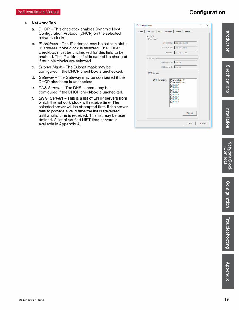
4. Network Tab
a. DHCP – This checkbox enables Dynamic Host Configuration Protocol (DHCP) on the selected network clocks.
b. IP Address – The IP address may be set to a static IP address if one clock is selected. The DHCP checkbox must be unchecked for this field to be enabled. The IP address fields cannot be changed if multiple clocks are selected.
c. Subnet Mask – The Subnet mask may be configured if the DHCP checkbox is unchecked.
d. Gateway – The Gateway may be configured if the DHCP checkbox is unchecked.
e. DNS Servers – The DNS servers may be configured if the DHCP checkbox is unchecked.
f. SNTP Servers – This is a list of SNTP servers from which the network clock will receive time. The selected server will be attempted first. If the server fails to provide a valid time the list is traversed until a valid time is received. This list may be user defined. A list of verified NIST time servers is available in Appendix A.
Configuration
© American Time20
PoE Installation ManualConfiguration
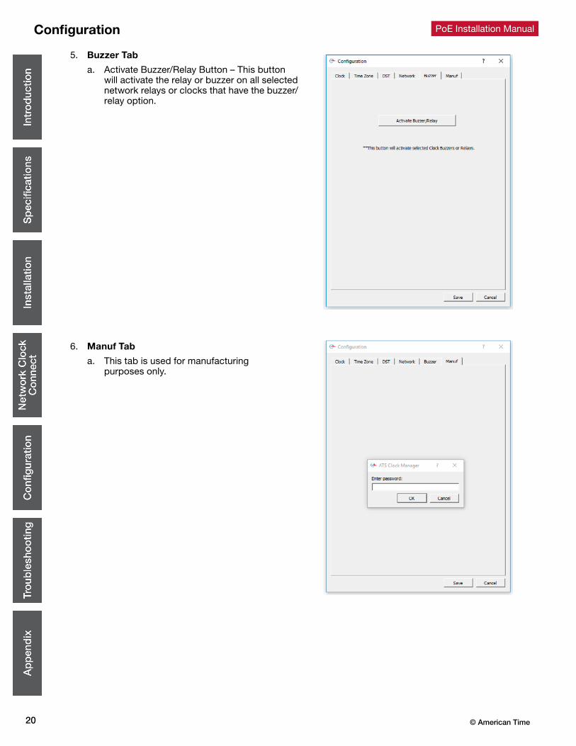
5. Buzzer Tab
a. Activate Buzzer/Relay Button – This button will activate the relay or buzzer on all selected network relays or clocks that have the buzzer/relay option.
6. Manuf Tab
a. This tab is used for manufacturing purposes only.
21© American Time
PoE Installation Manual Configuration
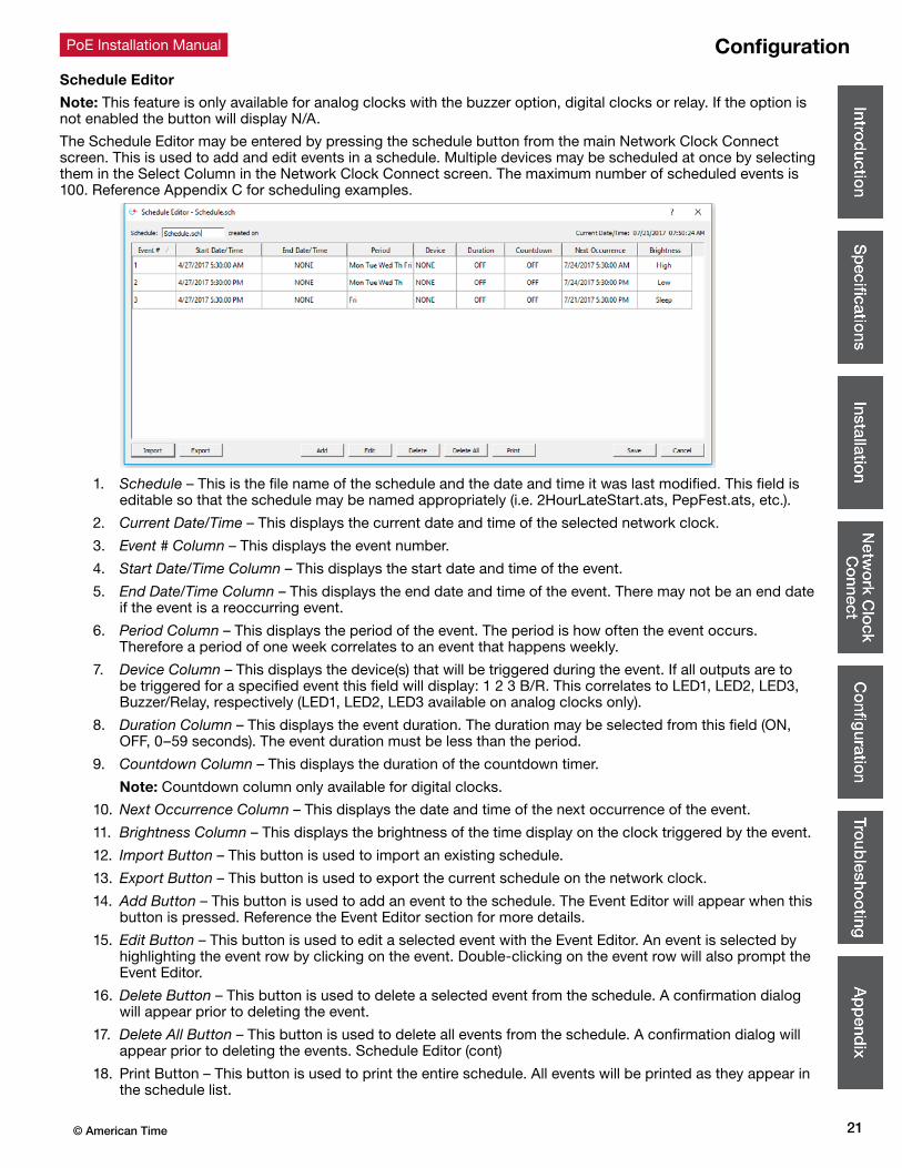
Schedule Editor
Note: This feature is only available for analog clocks with the buzzer option, digital clocks or relay. If the option is not enabled the button will display N/A.
The Schedule Editor may be entered by pressing the schedule button from the main Network Clock Connect screen. This is used to add and edit events in a schedule. Multiple devices may be scheduled at once by selecting them in the Select Column in the Network Clock Connect screen. The maximum number of scheduled events is 100. Reference Appendix C for scheduling examples.
1. Schedule – This is the file name of the schedule and the date and time it was last modified. This field is editable so that the schedule may be named appropriately (i.e. 2HourLateStart.ats, PepFest.ats, etc.).
2. Current Date/Time – This displays the current date and time of the selected network clock.
3. Event # Column – This displays the event number.
4. Start Date/Time Column – This displays the start date and time of the event.
5. End Date/Time Column – This displays the end date and time of the event. There may not be an end date if the event is a reoccurring event.
6. Period Column – This displays the period of the event. The period is how often the event occurs. Therefore a period of one week correlates to an event that happens weekly.
7. Device Column – This displays the device(s) that will be triggered during the event. If all outputs are to be triggered for a specified event this field will display: 1 2 3 B/R. This correlates to LED1, LED2, LED3, Buzzer/Relay, respectively (LED1, LED2, LED3 available on analog clocks only).
8. Duration Column – This displays the event duration. The duration may be selected from this field (ON, OFF, 0–59 seconds). The event duration must be less than the period.
9. Countdown Column – This displays the duration of the countdown timer.
Note: Countdown column only available for digital clocks.
10. Next Occurrence Column – This displays the date and time of the next occurrence of the event.
11. Brightness Column – This displays the brightness of the time display on the clock triggered by the event.
12. Import Button – This button is used to import an existing schedule.
13. Export Button – This button is used to export the current schedule on the network clock.
14. Add Button – This button is used to add an event to the schedule. The Event Editor will appear when this button is pressed. Reference the Event Editor section for more details.
15. Edit Button – This button is used to edit a selected event with the Event Editor. An event is selected by highlighting the event row by clicking on the event. Double-clicking on the event row will also prompt the Event Editor.
16. Delete Button – This button is used to delete a selected event from the schedule. A confirmation dialog will appear prior to deleting the event.
17. Delete All Button – This button is used to delete all events from the schedule. A confirmation dialog will appear prior to deleting the events. Schedule Editor (cont)
18. Print Button – This button is used to print the entire schedule. All events will be printed as they appear in the schedule list.

© American Time22
PoE Installation Manual
Schedule Editor (cont.)
19. Save Button – This button is used to Save the current schedule. The schedule name and last modified date will be updated. If multiple clocks were selected in the Network Clock Connect screen, the Other Clocks Selected prompt will appear. This allows all of the selected clocks to be updated with the same schedule.
20. Cancel Button – This button is used to cancel any changes made to the schedule.
Event Editor
The Event Editor may be entered by adding a new event or editing an existing event in the Schedule Editor. Here the event is defined with a start date/time, end date/time (optional), period, duration, and device selection. Reference Appendix C for event entry examples. The maximum number of scheduled events is 100.
1. Current Date/Time – This displays the current date and time of the selected network clock.
2. Schedule – This displays the filename of the schedule in which the event resides. The last modified date and time is also displayed.
3. Start Date Calendar – This is used to select the start date of the event. A date selection prior to the current date is not possible.
4. Start Time (HH:MM:SS) – This is used to select the start time of the event.
5. Specify End Date/Time – This checkbox is used to define an end date and time for the event. The event will be a reoccurring event if this checkbox is not selected. The End Date Calendar and End Time will not be enabled unless this box is checked.
6. End Date Calendar – This is used to select the end date of the event. An end date cannot be selected unless the Specify End Date/Time checkbox is checked. A date selection prior to the current date is not possible.
7. End Time (HH:MM:SS) – This is used to select the end time of the event. The end time cannot be defined unless the Specify End Date/Time checkbox is checked.
8. Period – This is used to define the period of the event. The period is the interval of time between event occurrences. An entry of 0 will disable the event. A numeric value must be entered into the text field. The pull-down menu consists of seconds, minutes, hours, days, and weeks. Here are the possible entries per period duration:
• <x> seconds – 0<x<60
• <x> minutes – 0<x<60
• <x> hours – 0<x<24
• <x> days – 0<x<366
• <x> weeks – 0<x<54
Note: Select a period of one day in order to specify days on which the event will occur.
Configuration
Relay/Analog Clock Buzzer Event Editor Digital Clock Event Editor

23© American Time
PoE Installation Manual Configuration
Event Editor (cont.)
9. Device – This is used to select the devices that will trigger for this event. Any combination of LED 1, LED 2, LED 3 and Buzzer/Relay may be selected.
10. Duration – This is used to define the duration of the event (ON, OFF, 0–59 seconds). The event duration must be less than the period.
11. Brightness – This is used to schedule a change in brightness on the clock display. (High, Low, Sleep, Off).
Note: Brightness settings only available for digital clocks.
12. Countdown Duration (Min) – This is used to define the duration of the Countdown timer (Off, 1 Minute-59 Minutes).
Note: Countdown Duration (Min) settings are only available for digital clocks.
13. Save Button – This saves the event entry into the schedule.
14. Cancel Button – This cancels the event entry.
Web Browser InterfaceEach clock may also be configured using a web browser. Not all configurations that are in the Network Clock Connect application are available in the web interface. Network, time zone, and daylight saving time configurations are available in the web interface. Internet Explorer, Firefox, and Chrome are all supported web browsers.
First the IP address of the clock must be obtained to use the web interface. This can be obtained by using the Network Clock Connect application. Once the IP address is obtained, enter the address into the URL bar of the browser. The page at left should be displayed.
The default password is clock4u. Once the password has been entered click on the Authenticate button to log into the web interface.
Network
All changes require the Save Settings button to be clicked. For the changes to take effect, the Restart button must be clicked.
By default the network parameters are set up using DHCP. In order to set static values, uncheck the DHCP check box and enter new values in the address fields. If the values aren’t changed, the current addresses will be kept. The PoE clock must be restarted for these changes to take effect. Addresses in the Network section must be entered in IPv4, dotted quad, format (xxx.xxx.xxx.xxx).
© American Time24
PoE Installation ManualConfiguration
Network (cont)
When a DHCP network is not present at intial start-up, the PoE clock will default to a random Static IP address in the range of 169.254.1.0 to 169.254.254.255.
For analog clocks the IP address may be reset by restoring the clock to factory defaults by holding in the Default Button for 9-12 seconds. Both Status and Relay LEDs will flash for 5 seconds to confirm the defaults setting. Please reference the DHCP troubleshooting section if you are experiencing DHCP issues.
For digital clocks the IP address may be reset by restoring the clock to factory defaults using the following steps:
1. Remove power to the clock for at least 2 seconds (disconnect the patch cable from the back of the clock).
2. Hold down the Set button on the back of the clock.
3. Apply power back to the clock (reconnect the powered patch cable to the clock) while continuing to hold down the Set button.
4. 888 should scroll across the clock display.
5. Release the Set button.
Time Synchronization
• All changes require the Save Settings button to be clicked. For the changes to take effect, the Restart button must be clicked.
1. SNTP Servers – This is a list of NP servers from which the network clock will receive time. The selected server will be attempted first. If the server fails to provide a valid time the list is traversed until a valid time is received. This list may be user defined. A list of verified NIST time servers is available in Appendix A.
2. Time Zone – The Time Zone entry sets the time zone. Selecting the CUSTOM time zone will enable the Custom Time Zone fields. Reference Appendix B for a list of all available time zone configurations.
3. SNTP Resync Period (HH:MM) – The SNTP Resync Period is used to determine how often the clock requests the time from the SNTP server. The default and recommended interval for the clock to resync is every 15 minutes.
Use 12 Hour Format
• All changes require the Save Settings button to be clicked. For the changes to take effect, the Restart button must be clicked.
This allows the user to select between 12 and 24 hour time display. Note: Available only for digital clocks.
Daylight Saving Time
• All changes require the Save Settings button to be clicked. For the changes to take effect, the Restart button must be clicked.
Daylight Saving Time (DST) varies greatly from one country to another and sometimes even within countries themselves. As a result, there are many parameters used to handle all of the various rules in use throughout the world. The default setting uses the rule observed by the majority of the United States.
1. Daylight Saving Time – The Daylight Saving Time entry is used to set the DST to AUTO, OFF, or CUSTOM. The AUTO selection is the standard DST for the United States.
Note: Not all time zone selections will allow for changing the DST to AUTO or OFF. For example, if USCT – USA Central is selected for the time zone then the DST cannot be set to OFF. However, this may be done by selecting UTC-6 for the time zone and selecting the DST to OFF. Reference Appendix B for a list of all available DST configurations.
2. Fixed Day – The Fixed Day check box will be enabled if the Daylight Saving Time is set to CUSTOM. It is used to indicate whether or not DST occurs on a specific date. For example, if DST started on March 1st of every year, the Fixed Day box needs to be checked. The Fixed Day check box changes how the Start and Stop parameters function. If the box is checked, the Day of Week and Week of Month portion of the Start and Stop parameters are disabled. If the box is not checked, the Date portion of the Start and Stop parameters is disabled. The default setting is to have the box unchecked (Fixed Day disabled).
3. Start/End Date/Time – The Start and Stop parameters indicate when DST changes occur. These parameters are available when CUSTOM DST is desired (continued on next page).

25© American Time
PoE Installation Manual
• Fixed Day-
• Floating Day-
Note: The default is set using the rule observed by the United States which starts on the second Sunday in March at 2:00 AM and ends on the first Sunday in November at 2:00 AM. The Daylight Saving Time selection may be set to AUTO or Custom with the following settings:
4. Hour Bias (± Hour:Min) – The Hour Bias determines the bias during DST. A bias of +1:0 will advance the clocks ahead 1 hour at the start of DST and fall back 1 hour at the end of DST.
Clock Type and Date Mode
• All changes require the Save Settings button to be clicked. For the changes to take effect, the Restart button must be clicked.
1. Clock Type– This displays the clock type. This is not configurable.
2. Date Mode – This is used to select the date mode of the Digital Calendar Clock.
3. Display Duration – This is used to set the duration of the time/date displays for a Digital Calendar Clock. If both time and date are set to “0”, only the time will be displayed. If date is set to “0” and time is set to anything other than “0”, only the date will be displayed. If neither time nor date are “0”, the time and date will toggle for the durations specified.
Other Configurations
• All changes require the Save Settings button to be clicked. For the changes to take effect, the Restart button must be clicked.
1. Unit Name – The Unit Name is used to name and identify each clock. The name may consist of up to 20 alphanumeric characters.
2. Password – The password field displays the current password. To change the password, enter a new password, click on the Save Settings button and then click on the Restart button. The default password is clock4u.
3. Brightness – the Brightness selection is used to change the brightness of the time display on the clock. (High, Low, Sleep, Off). When in the Sleep setting, the time segments of the display will be off. Every 20 seconds the time segments will display the time for 2-3 seconds in a Low brightness and turn off again
Note: The Brightness setting is only available for digital clocks.
Configuration
Fixed Day
Start Day
Start Time
Stop Date
Stop Time
2nd Sun
02 00
02 00
Mar 8th
1st Sun Nov 1st
Fixed Day
Start Day
Start Time
Stop Date
Stop Time
2nd Sun
02 00
02 00
Mar 8th
1st Sun Nov 1st
+
Fixed DayDaylight Saving Time
Start Day
Start Time
Stop Date
Stop Time
Hour Bias
2nd
CUSTOM
1 Hours 00 Minutes
Sun
02 00
02 00
Mar 8th
1st Sun Nov 1st

© American Time26
PoE Installation ManualRelay/Analog Clock Troubleshooting: DHCP
When a DHCP network is not present at initial start-up, the PoE clock will default to a random Static IP in the range of 169.254.1.0 to 169.254.254.255. The status LED will be illuminated red. If unable to obtain an IP address through DHCP, follow these troubleshooting steps:
1. Verify that there is power to the PoE clock. The Status LED of the PoE receiver will be illuminated if there is power to the clock.
2. Verify the Ethernet cable connection to the PoE clock. Make sure the patch cable is securely connected and not damaged. Have the cable tested or connect another Ethernet device to this cable to confirm proper connection.
3. Verify with the Network Administrator to ensure that DHCP is enabled on the network you are connecting the PoE clocks.
4. Verify that DHCP is enabled on the PoE receiver.
a. Configure a PC that is on the same local network as the PoE receiver, with the following network configurations:
Tip: Note existing PC settings first. Contact your Network Administrator for assistance or reference the following link: https://support.microsoft.com/en-us/help/15089/windows-change-tcp-ip-settings
• IP address: 169.254.0.1
• Subnet Mask: 255.255.0.0
b. Using the Network Clock Connect application, press the Refresh List button
c. Select the clock that was not receiving DHCP (IP address should be in the range of 169.254.1.0 and 169.254.254.255), and press the Configure button
d. Click on the Network tab and verify that the DHCP checkbox is selected
B – Status LED
C – Buzzer/Relay LED
D – Default Button
F – PoE Receiver/Relay
5. Return PC to the previous settings noted above in Step 4.
If the problem cannot be resolved after following these steps, please call Technical Support at American Time at
800-328-8996.
B DC
F
27© American Time
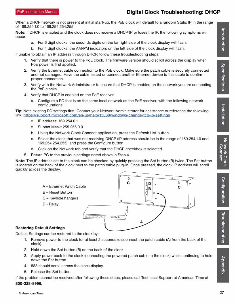
PoE Installation Manual Digital Clock Troubleshooting: DHCP
When a DHCP network is not present at initial start-up, the PoE clock will default to a random Static IP in the range of 169.254.1.0 to 169.254.254.255.
Note: If DHCP is enabled and the clock does not receive a DHCP IP or loses the IP, the following symptoms will occur:
a. For 6 digit clocks, the seconds digits on the far right side of the clock display will flash.
b. For 4 digit clocks, the AM/PM indicators on the left side of the clock display will flash.
If unable to obtain an IP address through DHCP, follow these troubleshooting steps:
1. Verify that there is power to the PoE clock. The firmware version should scroll across the display when PoE power is first applied.
2. Verify the Ethernet cable connection to the PoE clock. Make sure the patch cable is securely connected and not damaged. Have the cable tested or connect another Ethernet device to this cable to confirm proper connection.
3. Verify with the Network Administrator to ensure that DHCP is enabled on the network you are connecting the PoE clocks.
4. Verify that DHCP is enabled on the PoE receiver.
a. Configure a PC that is on the same local network as the PoE receiver, with the following network configurations:
Tip: Note existing PC settings first. Contact your Network Administrator for assistance or reference the following link: https://support.microsoft.com/en-us/help/15089/windows-change-tcp-ip-settings
• IP address: 169.254.0.1
• Subnet Mask: 255.255.0.0
b. Using the Network Clock Connect application, press the Refresh List button
c. Select the clock that was not receiving DHCP (IP address should be in the range of 169.254.1.0 and 169.254.254.255), and press the Configure button
d. Click on the Network tab and verify that the DHCP checkbox is selected
5. Return PC to the previous settings noted above in Step 4.
Note: The IP address set to the clock can be checked by quickly pressing the Set button (B) twice. The Set button is located on the back of the clock next to the patch cable plug-in. Once pressed, the clock IP address will scroll quickly across the display.
Restoring Default Settings
Default Settings can be restored to the clock by:
1. Remove power to the clock for at least 2 seconds (disconnect the patch cable (A) from the back of the clock).
2. Hold down the Set button (B) on the back of the clock.
3. Apply power back to the clock (connecting the powered patch cable to the clock) while continuing to hold down the Set button.
4. 888 should scroll across the clock display.
5. Release the Set button.
If the problem cannot be resolved after following these steps, please call Technical Support at American Time at
800-328-8996.
A
B CC D
A – Ethernet Patch Cable
B – Reset Button
C – Keyhole hangers
D - Relay

© American Time28
PoE Installation ManualTroubleshooting Clock Time
When the time displayed in the Network Clock Connect application is incorrect, follow the steps below:
1. Verify that the SNTP servers are working.
2. Verify that the SNTP server addresses are properly entered into the Network Tab.
3. Ping the SNTP servers with a PC on the same local network as the network clock(s).
4. Verify with the network administrator that Port 123 is open for SNTP time synchronization.
5. If the SNTP servers do not respond, update the NTP Servers List with new SNTP Servers. When the time displayed on the clock(s) differs from the Network Clock Connect application, follow the steps below:
6. Press the Refresh List button to refresh the time displayed in the application.
For Analog Clocks:
7. Home hands using Instruction Sheet 3133 for H004640 movement.Call American Time if you need assistance.
Note: The hands may be off by minutes or seconds if the clock has been jarred. This procedure will reset the hands to 12 o’clock.
If the problem cannot be resolved after following these steps, please call Technical Support at American Time at 800-328-8996.

29© American Time
PoE Installation Manual Appendix A: NIST Internet Time Servers
Please reference http:/tf.nist.gov/tf-cgi/servers.cgi for the latest NIST Internet Time servers list, which includes the status of each server.
Appendix B: Supported Time ZonesTime Zone
Code Description Hours Difference from UTC (Winter)
Hours Difference from UTC (Summer)
Auto DST Adjustment?
00 LMT (Local Mean Time) - based on longitude CALCULATED CALCULATED CONFIG
01 USA Alaska -9 -8 YES
02 USA Aleutian (HAST/HADT) -10 -9 YES
03 USA Arizona -7 -7 NO
04 USA Atlantic / Puerto Rico (AST) -4 -4 NO
05 USA Central (CST/CDT) -6 -5 YES
06 USA Chammoro (chST) +10 +10 NO
07 USA Eastern (EST/EDT) -5 -4 YES
08 USA Hawaii (HST) -10 -10 NO
09 USA Indiana East (USIND) -5 -5 NO
10 USA Mountain (MST/MDT) -7 -6 YES
11 USA Pacific (PST/PDT) -8 -7 YES
12 USA Midway Island / Samoa (SST) -11 -11 NO
13 USA Wake Islands (WAKT) +11 +11 NO
14 UTC+0 +0 +0 CONFIG
15 UTC+1 +1 +1 CONFIG
16 UTC+2 +2 +2 CONFIG
17 UTC+3 +3 +3 CONFIG
18 UTC+4 +4 +4 CONFIG
19 UTC+5 +5 +5 CONFIG
20 UTC+6 +6 +6 CONFIG
21 UTC+7 +7 +7 CONFIG
22 UTC+8 +8 +8 CONFIG
23 UTC+9 +9 +9 CONFIG
24 UTC+10 +10 +10 CONFIG
25 UTC+11 +11 +11 CONFIG
26 UTC+12 +12 +12 CONFIG
27 UTC+13 +13 +13 CONFIG
28 UTC-1 -1 -1 CONFIG
29 UTC-2 -2 -2 CONFIG
30 UTC-3 -3 -3 CONFIG
31 UTC-4 -4 -4 CONFIG
32 UTC-5 -5 -5 CONFIG
33 UTC-6 -6 -6 CONFIG
34 UTC-7 -7 -7 CONFIG
35 UTC-8 -8 -8 CONFIG
36 UTC-9 -9 -9 CONFIG
37 UTC-10 -10 -10 CONFIG
38 UTC-11 -11 -11 CONFIG
39 UTC-12 -12 -12 CONFIG
99 Custom Time Zone CONFIG CONFIG CONFIG
© American Time30
PoE Installation Manual
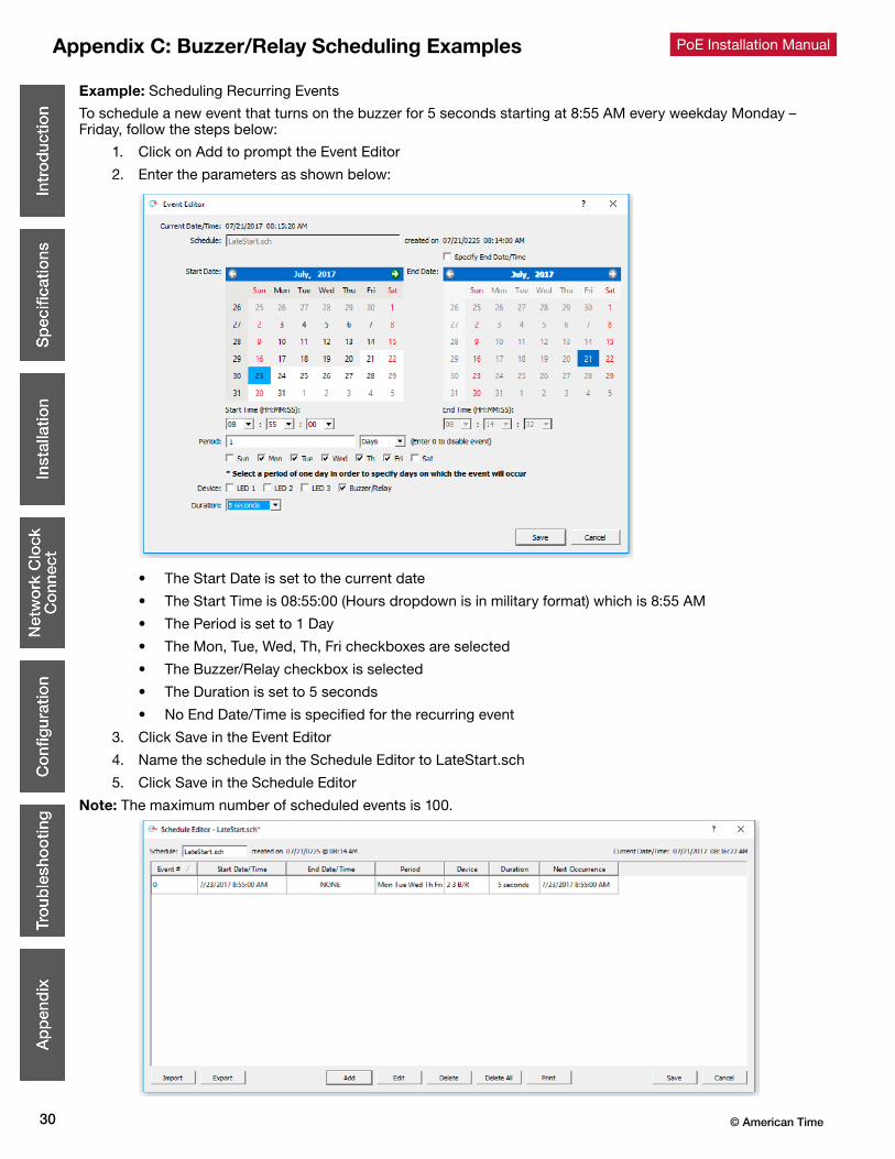
Example: Scheduling Recurring Events
To schedule a new event that turns on the buzzer for 5 seconds starting at 8:55 AM every weekday Monday – Friday, follow the steps below:
1. Click on Add to prompt the Event Editor
2. Enter the parameters as shown below:
• The Start Date is set to the current date
• The Start Time is 08:55:00 (Hours dropdown is in military format) which is 8:55 AM
• The Period is set to 1 Day
• The Mon, Tue, Wed, Th, Fri checkboxes are selected
• The Buzzer/Relay checkbox is selected
• The Duration is set to 5 seconds
• No End Date/Time is specified for the recurring event
3. Click Save in the Event Editor
4. Name the schedule in the Schedule Editor to LateStart.sch
5. Click Save in the Schedule Editor
Note: The maximum number of scheduled events is 100.
Appendix C: Buzzer/Relay Scheduling Examples
31© American Time
PoE Installation Manual
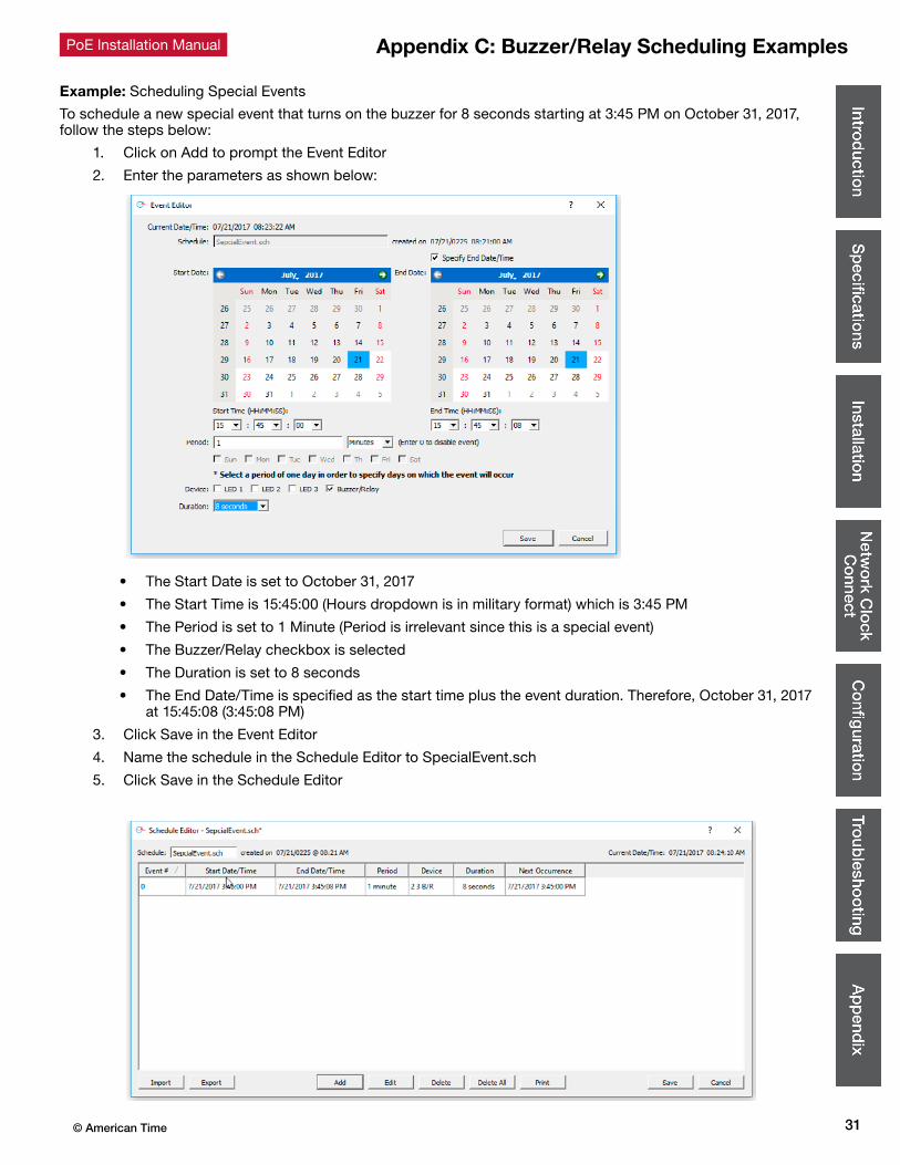
Example: Scheduling Special Events
To schedule a new special event that turns on the buzzer for 8 seconds starting at 3:45 PM on October 31, 2017, follow the steps below:
1. Click on Add to prompt the Event Editor
2. Enter the parameters as shown below:
• The Start Date is set to October 31, 2017
• The Start Time is 15:45:00 (Hours dropdown is in military format) which is 3:45 PM
• The Period is set to 1 Minute (Period is irrelevant since this is a special event)
• The Buzzer/Relay checkbox is selected
• The Duration is set to 8 seconds
• The End Date/Time is specified as the start time plus the event duration. Therefore, October 31, 2017 at 15:45:08 (3:45:08 PM)
3. Click Save in the Event Editor
4. Name the schedule in the Schedule Editor to SpecialEvent.sch
5. Click Save in the Schedule Editor
Appendix C: Buzzer/Relay Scheduling Examples

© American Time32
PoE Installation Manual
Example: Scheduling Display Brightness Events (Digital Clocks)
To schedule a new special event that dims the clocks display over the weekend to save energy, follow the steps below:
In this example, two events will be used. Event #0 will turn the clocks display to a Low Brightness state every Saturday at 12:00 AM starting on July 22nd. Event #1 will turn the clocks display back to a High Brightness state every Monday at 12:00 AM, starting on July 23th.
1. Click on Add to prompt the Event Editor
2. Enter the parameters as shown below:
Event #0
• The Start Date is set to September 10, 2011
• The Start Time is 00:00:00 (Hours dropdown is in military format) which is 12:00 AM
• The Period is set to 1 Day
• The Sat checkbox is selected
• The Buzzer/Relay checkbox is not selected
• The Duration is set to 2 seconds (Duration is irrelevant as long as it is not set to ON or OFF for this example)
• Brightness is set to Low (Sleep Mode could also be used for this example)
• Countdown Duration is set to Off (available only with clocks with countdown functionality)
• No End Date/Time is specified for the recurring event
3. Click Save in the Event Editor
4. Click on Add to prompt the Event Editor
Appendix D: Brightness Control Scheduling Example

33© American Time
PoE Installation Manual
5. Enter the parameters as shown below:
Event #1
• The Start Date is set to July 23, 2017
• The Start Time is 00:00:00 (Hours dropdown is in military format) which is 12:00 AM
• The Period is set to 1 Day
• The Mon checkbox is selected
• The Buzzer/Relay checkbox is not selected
• The Duration is set to 2 seconds (Duration is irrelevant as long as it is not set to ON or OFF for this example)
• Brightness is set to High
• Countdown Duration is set to Off (available only with clocks with countdown functionality)
• No End Date/Time is specified for the recurring event
6. Name the schedule in the Schedule Editor to BrightnessEvent.sch
7. Click Save in the Schedule Editor
Appendix D: Brightness Control Scheduling Example