Embed Size (px)
Citation preview

Installation and Operation Instructions Document 1218A
H23
3050
0A
WARNINGIf the information in this manual is notfollowed exactly, a fire or explosion mayresult causing property damage, personalinjury or loss of life.
Do not store or use gasoline or otherflammable vapors and liquids in the vicinityof this or any other appliance.
WHAT TO DO IF YOU SMELL GAS• Do not try to light any appliance.• Do not touch any electrical switch; do not
use any phone in your building.• Immediately call your gas supplier from a
nearby phone. Follow the gas supplier'sinstructions.
• If you cannot reach your gas supplier, callthe fire department.
Installation and service must be performed bya qualified installer, service agency, or gassupplier.
FOR YOUR SAFETY: This product must be installed and serviced by a professional service technician,qualified in hot water boiler and heater installation and maintenance. Improper installation and/or operationcould create carbon monoxide gas in flue gases which could cause serious injury, property damage, ordeath. Improper installation and/or operation will void the warranty.
AVERTISSEMENTAssurez-vous de bien suivres les instructionsdonnées dans cette notice pour réduire auminimum le risque d’incendie ou d’explosion oupour éviter tout dommage matériel, touteblessure ou la mort.
Ne pas entreposer ni utiliser d’essence nid’autres vapeurs ou liquides inflammables dansle voisinage de cet appareil ou de tout autreappareil.QUE FAIRE SI VOUS SENTEZ UNE ODEUR DE GAZ:
• Ne pas tenter d’allumer d’appareils.• Ne touchez à aucun interrupteur. Ne pas vous
servir des téléphones dansle bâtiment où vousvous trouvez.
• Appelez immédiatement votre fournisseur degaz depuis un voisin. Suivez les instructionsdu fournisseur.
• Si vous ne pouvez rejoindre le fournisseur degaz, appelez le sservice des incendies.
L’installation et l’entretien doivent être assurés parun installateur ou un service d’entretien qualifié oupar le fournisseur de gaz.
Installation and OperationInstructions for
NeoTherm®
Modulating BoilerModel NTH
Sizes 080–500 MBTU/h

LAARS Heating SystemsPage 2
TABLE OF CONTENTS
SECTION 1.General Information1.1 Introduction ...................................................... 31.2 Model Identification ......................................... 31.3 Appliance Overview ......................................... 31.4 Warranty .......................................................... 31.5 Unpacking ....................................................... 41.6 Dimensions ...................................................... 41.7 Locating the Appliance .................................... 41.8 Locating Appliance for Correct Vent Distance
from Outside Wall or Roof Termination ........... 8
SECTION 2.Venting and Combustion Air2.1 Combustion Air ................................................ 82.1.1 Combustion Air From Room ............................ 82.1.2 Intake Combustion Air ..................................... 92.2 Venting ............................................................ 92.3 Locating Vent & Combustion Air Terminals ... 112.3.1 Side Wall Vent Terminal ................................ 122.3.2 Side Wall Combustion Air Terminal ............... 122.3.3 Vertical Vent Terminal ................................... 122.3.4 Vertical Combustion Air Terminal .................. 122.3.5 Installations in the Commonwealth
of Massachusetts .......................................... 122.4 Common Vent Test ....................................... 12
SECTION 3.Gas Supply and Piping3.1 Gas Supply and Piping .................................. 13
SECTION 4.Water Connections4.1 Heating System Piping:
Hot Supply Connections ................................ 144.2 Cold Water Make-Up ..................................... 144.3 Freeze Protection .......................................... 144.4 Recognized Chemicals .................................. 16
SECTION 5.Electrical Connections5.1 Main Power ................................................... 215.2 Control Features ............................................ 215.2.1 User Mode ..................................................... 215.2.1.1 Temperature Control Point Adjustment ......... 215.2.1.2 Direct Hot Water Control Point Adjustment ... 215.2.2 Setup Mode ................................................... 215.2.2.1 Adjusting the Temperature Display
Units in °F or °C............................................. 22
5.2.2.2 Adjusting the Outdoor Reset On or Off .......... 225.2.2.3 Adjusting Low Boiler Temperature Setpoint .. 225.2.2.4 Adjusting High Outdoor Temperature
Setpoint ......................................................... 225.2.2.5 Adjusting Low Outdoor Temperature
Setpoint ......................................................... 225.2.2.6 Anti Short Cycle Time .................................... 225.2.3 Diagnostic Mode............................................ 225.2.3.1 High Limit Setting .......................................... 225.2.3.2 DHW Limit Setting ......................................... 225.3 Pump Connections ........................................ 235.4 Temperature Control ..................................... 235.5 Temperature Control - Indirect Tank ............. 235.6 Outdoor Reset Operation .............................. 235.7 External Control Connections ........................ 235.8 Wiring Diagram.............................................. 24
SECTION 6.Operating Instructions6.1 Filling the Boiler System ................................ 266.2 Operating the Burner and Set Up .................. 266.2.1 Burner Operation ........................................... 266.2.2 Boiler Setpoint and Adjustment ..................... 276.3 Shutting Down the NeoTherm ....................... 286.4 To Restart the NeoTherm .............................. 28
SECTION 7.Maintenance7.1 System Maintenance ..................................... 287.2 Appliance Maintenance and
Component Description ................................. 297.2.1 Burner ............................................................ 297.2.2 Modulating Gas Valve / Venturi ..................... 307.2.3 Appliance Control .......................................... 307.2.4 Ignitor Assembly ............................................ 307.2.5 Flame Sensor ................................................ 307.2.6 Transformers ................................................. 307.2.7 Blower ........................................................... 307.2.8 Heat Exchanger Coils .................................... 307.2.9 Gas Pressure Switches (optional) ................... 31
SECTION 8.Trouble Shooting8.1 Sequence of Operation ................................. 318.2 Short Cycling ................................................. 328.3 Error Codes ................................................... 32
SECTION 9.Replacement Parts9.1 General Information ....................................... 329.2 Parts List ....................................................... 33

NeoTherm Boiler Page 3
SECTION 1.General Information
WARNINGThe NeoTherm hydronic boiler must be installed inaccordance with the procedures detailed in thismanual, or the LAARS Heating Systems warranty willbe voided. The installation must conform to therequirements of the local jurisdiction having authority,and, in the United States, to the latest edition of theNational Fuel Gas Code, ANSI Z223.1/NFPA54. InCanada, the installation must conform to the latestedition of CSA B149.1 Natural Gas and PropaneGas Installation Code, and/or local codes. Whererequired by the authority having jurisdiction, theinstallation of NeoTherm boilers must conform to theStandard for Controls and Safety Devices forAutomatically Fired Boilers, ANSI/ASME CSD-1. Anymodifications to the boiler, its gas controls, or wiringmay void the warranty. If field conditions requiremodifications, consult the factory representativebefore initiating such modifications.
1.1 IntroductionThis manual provides information necessary for
the installation, operation, and maintenance of LAARSHeating Systems NeoTherm appliances. Read itcarefully before installation.
All application and installation procedures shouldbe reviewed completely before proceeding with theinstallation. Consult the LAARS Heating Systemsfactory, or local factory representative, with anyproblems or questions regarding this equipment.Experience has shown that most operating problems arecaused by improper installation.
The NeoTherm appliance is protected against overpressurization. A pressure relief valve is fitted to allappliances. It is installed inside the jacket (see Section 4for instructions on how to pipe the relief valve outlet).IMPORTANT: The inlet gas pressure to the appliancemust not exceed 13" W.C. (3.2kPa).
All installations must be made in accordance with1) American National Standard Z223.1/NFPA54-LatestEdition “National Fuel Gas Code” or 2) CSA B149.1
“Natural Gas and Propane Installation Code” and withthe requirement of the local utility or other authoritieshaving jurisdiction. Such applicable requirements takeprecedence over the general instructions containedherein.
All electrical wiring is to be done in accordancewith the local codes, or in the absence of local codes,with: 1) The National Electrical Code ANSI/NFPA No.70-latest Edition, or 2) CSA STD. C22.1 “CanadianElectrical Code - Part 1”. This appliance must beelectrically grounded in accordance with these codes.
1.2 Model IdentificationConsult the rating plate on the unit. The following
information describes the model number structure.(1-2) Model Series Designation
N T = NeoTherm(3) Usage
H = Hydronic(4-6) Size
0 8 0 = 80,000 BTU/hr input1 0 5 = 105,000 BTU/hr input1 5 0 = 150,000 BTU/hr input2 1 0 = 210,000 BTU/hr input2 8 5 = 285,000 BTU/hr input3 9 9 = 399,000 BTU/hr input5 0 0 = 500,000 BTU/hr input
(7) FuelN = Natural GasP = LP Gas
(8) Options CodeX = Standard UnitJ = CSD-1, FM, GAP, IL Code (size 500 only)
(9) Pump OptionsN = Factory-mounted pump (standard)X = No pump
(10) Revision1 = First version
1.3 Appliance OverviewSee Figures 2 through 6.
1.4 WarrantyLAARS Heating Systems’ NeoTherm appliances
are covered by a limited warranty. The owner shouldcomplete the warranty registration at www.Laars.com.
All warranty claims must be made to an authorizedLAARS Heating Systems representative. Claims must
Model Nomenclature1 2 3 4 5 6 7 8 9 10
N T H 1
SERIESN T
USAGEH - HYDRONIC
SIZEMBTU/h0 8 01 0 51 5 02 1 02 8 53 9 95 0 0
FUELN - NATURALP - PROPANE
OPTIONS CODEX - STANDARDJ - CSD-1,
FM, GAP,IL (500 only)
PUMP OPTIONSN - PUMP-MTD
(standard)X - NO PUMP
REVISION1 - FIRST

LAARS Heating SystemsPage 4
include the serial number and model (this informationcan be found on the rating plate), installation date, andname of the installer. Shipping costs are not included inthe warranty coverage.
Some accessory items may be shipped in separatepackages. Verify receipt of all packages listed on thepacking slip. Inspect everything for damageimmediately upon delivery, and advise the carrier of anyshortages or damage. Any such claims should be filedwith the carrier. The carrier, not the shipper, isresponsible for shortages and damage to theshipment whether visible or concealed.
1.5 UnpackingThe NeoTherm is shipped in a single crate with the
following standard components packed on top of theappliance (see Figure 1):A. exhaust terminal C. temperature/pressure gaugeB. intake terminal D. alternate terminal screens1. Remove all packing and tie-down materials.2. Check contents of the carton against items shown.
1.6 DimensionsDimensions are shown in Figure 7.
1.7 Locating the ApplianceThe NeoTherm is for indoor installations only.
Figure 2. Location of Components, Sizes 80–105.
The appliance should be located to provideclearances on all sides for maintenance and inspection.It should not be located in an area where leakage of anyconnections will result in damage to the area adjacent tothe appliance or to lower floors of the structure.
When such a location is not available, it isrecommended that a suitable drain pan, adequatelydrained, be installed under the appliance.
The appliance is design certified by CSA-International for installation on combustible flooring; inbasements; in closets, utility rooms or alcoves.
Figure 1. Contents of Shipping Package.

NeoTherm Boiler Page 5
Figure 4. Location of Components, Size 285.
Figure 3. Location of Components, Sizes 150–210.
LAARS Heating SystemsPage 6
Figure 6. Location of Components, Size 500.
Figure 5. Location of Components, Size 399.

NeoTherm Boiler Page 7
Figure 7. Dimensional Drawing.
A B C D E F G H J K ConnectionsSIZE in in in in in in in in in in NPT Size (in)
water gas80 19-3/8 18-3/8 8 11-1/4 12 21-1/8 14 13-5/8 9-3/8 8-7/8 1 1/2
105 19-3/8 18-1/8 5-7/8 10-5/8 11-5/8 20-7/8 14-1/8 13-3/8 7-7/8 8-7/8 1 1/2150 19-3/8 18-1/8 3 10-3/4 7-1/2 19-3/8 14-1/8 13-1/4 5-1/8 8-7/8 1 1/2210 26-5/8 18-1/8 3-1/8 17-3/4 7-5/8 19-3/8 14-1/8 17-3/4 5-1/8 8-7/8 1 1/2285 26-5/8 18-1/2 5-3/4 14 17-3/4 19 14 20-1/8 5-1/8 8-3/4 1-1/4 3/4399 31-1/2 18-5/8 4-1/8 14-5/8 21-3/8 19 19-1/4 25 5-1/8 8-3/4 1-1/4 3/4500 37-3/4 18-3/4 4-1/8 14-7/8 27-5/8 19 2-3/4 29-3/4 5-1/8 8-3/4 1-1/2 1
A B C D E F G H J K ConnectionsSIZE cm cm cm cm cm cm cm cm cm cm NPT Size (in)
water gas80 49 47 20 29 30 54 36 35 24 23 1 1/2
105 49 46 15 27 30 53 36 34 20 23 1 1/2150 49 46 8 27 19 49 36 34 13 23 1 1/2210 68 46 8 45 19 49 36 45 13 23 1 1/2285 68 47 15 36 45 48 36 51 13 22 1-1/4 3/4399 80 47 10 37 54 48 49 64 13 22 1-1/4 3/4500 96 48 10 38 70 48 7 76 13 22 1-1/2 1

LAARS Heating SystemsPage 8
SECTION 2.Venting and Combustion Air
2.1 Combustion AirNeoTherm boilers and water heaters must have
provisions for combustion and ventilation air inaccordance with the applicable requirements forCombustion Air Supply and Ventilation in the NationalFuel Gas Code, ANSI Z223 1; or in Canada, the NaturalGas and Propane Installation Code, CSA B149.1. Allapplicable provisions of local building codes must alsobe adhered to.
A NeoTherm unit can take combustion air fromthe space in which it is installed, or the combustionair can be ducted directly to the unit. Ventilation airmust be provided in either case.
2.1.1 Combustion Air From RoomIn the United States, the most common
requirements specify that the space shall communicatewith the outdoors in accordance with method 1 or 2,which follow. Where ducts are used, they shall be of thesame cross-sectional area as the free area of theopenings to which they connect.
Method 1: Two permanent openings, onecommencing within 12" (300mm) of the top and onecommencing within 12" (300mm) of the bottom, of theenclosure shall be provided. The openings shallcommunicate directly, or by ducts, with the outdoors orspaces that freely communicate with the outdoors.When directly communicating with the outdoors, orwhen communicating to the outdoors through verticalducts, each opening shall have a minimum free area of 1square inch per 4000 Btu/hr (550 square mm/kW) oftotal input rating of all equipment in the enclosure.When communicating to the outdoors throughhorizontal ducts, each opening shall have a minimumfree area of not less than 1 square inch per 2000 Btu/hr(1100 square mm/kW) of total input rating of allequipment in the enclosure.
Method 2: One permanent opening, commencingwithin 12" (300mm) of the top of the enclosure, shall bepermitted. The opening shall directly communicate withthe outdoors or shall communicate through a vertical orhorizontal duct to the outdoors or spaces that directlycommunicate with the outdoors and shall have aminimum free area of 1 square inch per 3000 Btu/hr(734 square mm/kW) of the total input rating of allequipment located in the enclosure. This opening mustnot be less than the sum of the areas of all ventconnectors in the confined space.
Other methods of introducing combustion andventilation air are acceptable, providing they conform tothe requirements in the applicable codes listed above.
In Canada, consult local building and safety codes or,in absence of such requirements, follow CAN/CGA B149.
NeoTherm Boilers must never be installed oncarpeting. The location for the appliance should bechosen with regard to the vent pipe lengths and externalplumbing. The unit shall be installed such that the gasignition system components are protected from water(dripping, spraying, rain, etc.) during operation andservice (circulator replacement, control replacement,etc.). When vented vertically, the NeoTherm must belocated as close as practical to the vertical section of thevent. If the vent terminal and/or combustion air terminalterminate through a wall, and there is potential for snowaccumulation in the local area, both terminals should beinstalled at an appropriate level above grade or themaximum expected snow line.
The dimensions and requirements that are shownin Table 1 should be met when choosing the locationsfor the appliance.
1.8 Locating Appliance for Correct VentDistance from Outside Wall orRoof TerminationThe forced draft combustion air blower in the
appliance has sufficient power to vent properly whenthe guidelines in Table 2 are followed.NOTE: When located on the same wall, the NeoThermcombustion air intake terminal must be installed aminimum of 12" (30cm) below the exhaust vent terminal.
For concentric vent terminal kit (optional), followinstallation instructions included with the kit.
REQUIRED CLEARANCE FROM SUGGESTED SERVICE
APPLIANCE COMBUSTIBLE MATERIAL ACCESS CLEARANCE
SURFACE IN. CM IN. CM
Left Side 1 2.5 1 2.5Right Side 1 2.5 12 31Top 1 2.5 24 61Back 1 2.5 6 15Closet, Front 1 2.5 6 15Alcove, Front 1 2.5 24 61Vent 0 0 – –
Table 1. Clearances.
SIZE MAX EQUIVALENT* VENT LENGTH PVC/CPVC(EACH INTAKE AND EACH EXHAUST)
2" DIA / 5.1CM 3" DIA / 7/6CM 4" DIA / 10.2CM
80 40 ft 6.1M 100 ft 30.5M n/a105 40 ft 6.1M 100 ft 30.5M n/a150 n/a 100 ft 30.5M n/a210 n/a 100 ft 30.5M n/a285 n/a 20 ft 6.1M 100 ft 30.5M399 n/a n/a 100 ft 30.5M500 n/a n/a 100 ft 30.5M
* Each 90° fitting = 5 equivalent feet 1.5M
Table 2. Vent / Air Pipe Sizes.

NeoTherm Boiler Page 9
2.1.2 Intake Combustion AirThe combustion air can be taken through the wall,
or through the roof. When taken from the wall, it mustbe taken from out-of-doors by means of the LAARShorizontal wall terminal, shown in Table 3. See Table 2to select the appropriate diameter air pipe. When takenfrom the roof, a field-supplied rain cap or an elbowarrangement must be used to prevent entry of rain water(see Figure 8).
Use ABS, PVC, CPVC or galvanized pipe for thecombustion air intake (see Table 4), sized per Section 1.7.Route the intake to the heater as directly as possible. Sealall joints. Provide adequate hangers. The unit must notsupport the weight of the combustion air intake pipe. Max-imum linear pipe length allowed is shown in Table 2.Subtract 5 allowable linear ft. (1.5m) for every elbow used.
The connection for the intake air pipe is at the top ofthe unit. To aid in boiler service, a removable adapter isrecommended when making the connection to the boiler.
In addition to air needed for combustion, air shallalso be supplied for ventilation, including air required forcomfort and proper working conditions for personnel.
2.2 Venting WARNING
Failure to use CPVC or stainless steel venting for thefirst 16" of vent material or for any part of the ventingthat is installed inside a closet may lead to propertydamage, personal injury or death.
WARNINGFailure to use the appropriate vent material,installation techniques, glues/sealants could lead tovent failure causing property damage, personal injuryor death.
WARNINGAll venting must be installed according to this manualand any other applicable local codes, including butnot limited to, ANSI Z223.1/NFPA 54, CSA B149.1,CSAB149.2 and ULC-S636. Failure to follow thismanual and applicable codes may lead to propertydamage, severe injury, or death.
The NeoTherm is a Category IV appliance andmay be installed with PVC and CPVC that complieswith ANSI/ASTM D1785 F441, or a stainless steel
INSTALLATION STANDARDS
MATERIAL UNITED STATES CANADA
ABS ANSI/ASTM D1527 All venting must be ULC-S636 certified for use asPVC, sch 40 ANSI/ASTM D1785 or D2665 venting material. The venting material must be chosen
CPVC, sch 40 ANSI/ASTM F441 based upon the intended application of the boiler.
Table 4. Required Combustion Air Vent Material.
INSTALLATION STANDARDS
MATERIAL UNITED STATES CANADA
Stainless Steel UL 1738 All venting must be ULC-S636 certified for use asPVC, sch 40 ANSI/ASTM D178 venting material. The venting material must be chosen
CPVC, sch 40 ANSI/ASTM F441 based upon the intended application of the boiler.
Table 5. Required Exhaust Vent Material.
Figure 8. Combustion Air and Vent Through Roof.
HORIZONTAL INTAKE AND EXHAUST PVC VENT TERMINAL KITS2" PVC 3" PVC 4" PVC
SIZE Standard Concentric Standard Concentric StandardCA006000 CA005900 239-44069-01
80 included optional optional optional n/a105 included optional optional optional n/a150 n/a n/a included optional n/a210 n/a n/a included optional n/a285 n/a n/a optional optional included399 n/a n/a n/a n/a included500 n/a n/a n/a n/a included
Table 3. PVC Vent Terminal Kits.

LAARS Heating SystemsPage 10
*When vent terminal is less than 10 feet (3m) horizontallyfrom a forced air inlet, the terminal must be at least 3 feet(0.9m) above the air inlet.
Figure 9. Combustion Air and Vent Through Side Wall.
U.S. Installations (see note 1) Canadian Installations (see note 2)
A= Clearance above grade, veranda, porch, 12 inches (30 cm) 12 inches (30 cm)deck, or balcony See note 6 See note 6
B= Clearance to window or door that may be Direct vent only: 12 inches (30cm); 36 inches (91 cm)opened Other than Direct vent: 4 ft (1.2m) below or to
side of opening; 1 ft (30cm) above opening
C= Clearance to permanently closed window See note 4 See note 5
D= Vertical clearance to ventilated soffit locatedabove the terminal within a horizontal See note 4 See note 5distance of 2 feet (61cm) from the centerline of the terminal
E= Clearance to unventilated soffit See note 4 See note 5
F= Clearance to outside corner See note 4 See note 5
G= Clearance to inside corner See note 4 See note 5
H= Clearance to each side of center line 3 feet (91 cm) within a height 15 feet aboveextended above meter/regulator assembly See note 4 the meter/regulator assembly
I= Clearance to service regulator vent outlet See note 4 3 feet (91 cm)
J= Clearance to nonmechanical air supply Direct vent only: 12 inches (30cm);inlet to building or the combustion air inlet Other than Direct vent: 4 ft (1.2m) below or to 36 inches (91 cm)to any other appliance side of opening; 1 ft (30cm) above opening
K= Clearance to a mechanical air supply inlet 3 feet (91 cm) above if within 10 feet (3 m) 6 feet (1.83 m)horizontally
L= Clearance above paved sidewalk or paved Vent termination not allowed in this location Vent termination not allowed in this locationdriveway located on public property for category IV appliances. for category IV appliances.
M= Clearance under veranda, porch, deck, See note 4 12 inches (30 cm) (see note 3)or balcony
Notes:1. In accordance with the current ANSI Z223.1 / NFPA 54 National Fuel Gas Code.2. In accordance with the current CAN/CGA-B149 Installation Codes.3. Permitted only if veranda, porch, deck, or balcony is fully open on a minimum of two sides beneath the floor.4. For clearances not specified in ANSI Z223.1 / NFPA 54, clearance is in accordance with local installation codes and the requirements of the
gas supplier.5. For clearances not specified in CAN/CGA-B149, clearance is in accordance with local installation codes and the requirements of the gas
supplier.6. IMPORTANT: terminal must be placed such that it remains a minimum 12" above expected snow line. Local codes may have more
specific requirements, and must be consulted.
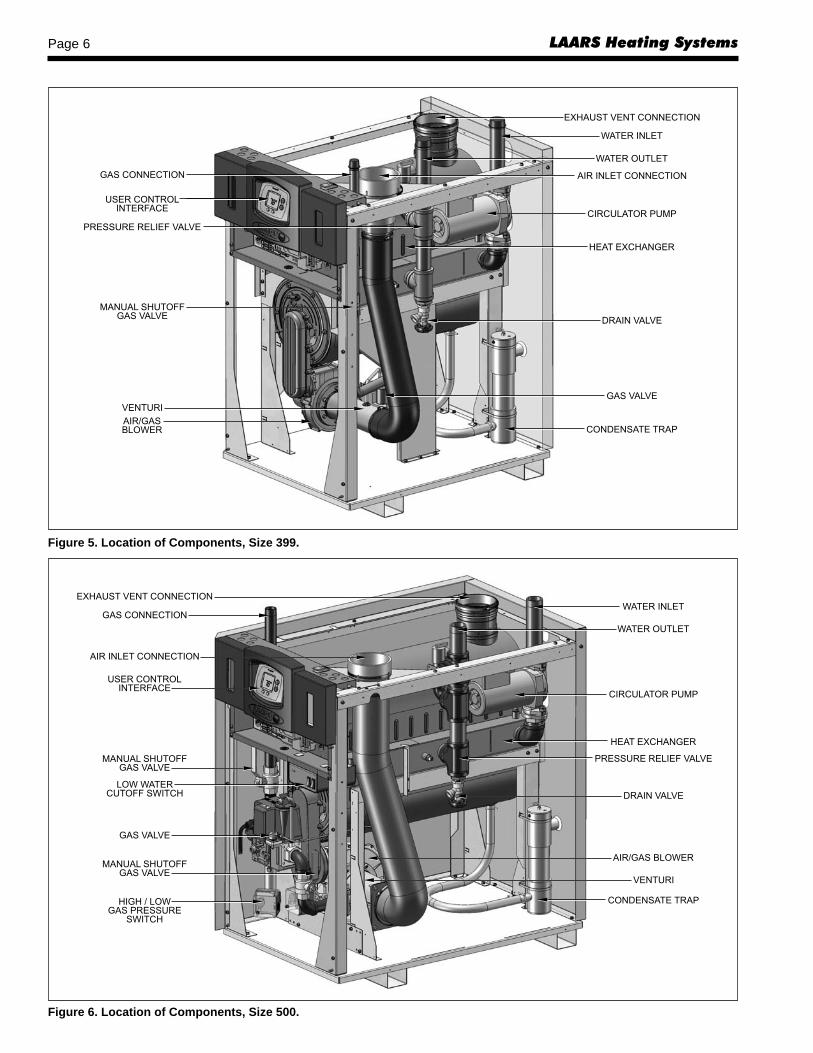
NeoTherm Boiler Page 11
venting system that complies with UL 1738 Standard(see Table 5).
Installations in Canada require the use ofventing material certified to ULCS636. All Gasvents connected to the NeoTherm, plastic, stainlesssteel or otherwise must be certified to this ULCstandard. Appropriate selection of vent material isvery important for proper performance and safeoperation of the NeoTherm. Vent material MUSTbe selected based upon operating conditions suchas outlet water temperature and installed location.
The flue temperature of the NeoThermchanges dramatically with changes in operatingwater temperature. Therefore, it is necessary toassess the application of the boiler to determine therequired certified vent class. If the NeoTherm isgoing to be installed in an application where theoutlet water temperature exceeds 145F, and/orinstalled in a closet, class IIB or higher ventmaterial is required. If the system temperaturesare unknown at the time of installation, class IIB orhigher venting material is recommended.
In Canada all venting used must meet thefollowing requirements:1. ULC-S636 certified and marked2. The first 3 feet of venting must be accessible
for visual inspection.3. All components used in the vent system must
be from a certified manufacturer.4 . Vent system components must not be mixed
with alternate manufacturers certifiedcomponents and/or unlisted components.
5 . The venting must be installed according to thevent manufacturers installation instructions.
The unit’s vent can terminate through the roof, orthrough an outside wall. It can be installed throughwalls that are 3" (7.6cm) to 12" (30cm) in thickness.
The venting should be connected to the 16" CPVCsection included with the boiler. The 16" section ofCPVC must be used to make the connection to the boiler.See Table 2 to select the appropriate vent pipe diameter.The vent pipe must pitch upward, toward the ventterminal, so that condensate will run back to theNeoTherm to drain. Route the vent pipe to the heater asdirectly as possible. Seal all joints and provide adequatehangers as required in the venting system manufacturer’sInstallation Instructions. Horizontal portions of theventing system must be supported to prevent sagging andmay not have any low sections that could trapcondensate. The unit must not support the weight of thevent pipe. Horizontal runs must slope upwards not lessthan ¼ inch per foot from the unit to the vent terminal.Up to 100 equivalent feet (30m) of pipe can be used.Subtract 5 feet (1.5m) for each elbow used.IMPORTANT NOTE ABOUT COMMON VENTING:A single vent that is shared by multiple NeoThermunits MUST be engineered by a competent venting
specialist, and involves the selection of draft inducingequipment, hardware and controls to properly balanceflue gas pressures. Do not common vent NeoThermunits unless the vent system meets thisrequirement. NeoTherm units are never permittedto share a vent with Category I appliances.
A condensate drain is built into the NeoTherm. Afloat switch monitors the condensate trap, and willopen if the condensate level gets too high. This willprevent the NeoTherm from firing if there is ablockage or overflow.
Connect a 3/4" PVC pipe between the drainconnection and a floor drain (or condensate pump if afloor drain is not accessible).
The condensate drain must be installed so as toprevent accumulation of condensate. When acondensate pump is not used, the tubing mustcontinuously slope downward toward the drain withno spiraling.
Consult local codes for disposal method.
CautionCondensate is mildly acidic (pH.....5), and may harmsome floor drains and/or pipes, particularly thosethat are metal. Ensure that the drain, drainpipe,and anything that will come in contact with thecondensate can withstand the acidity, or neutralizethe condensate before disposal. Damage causedby failure to install a neutralizer kit or toadequately treat condensate will not be themanufacturer’s responsibility.
2.3 Locating Vent & Combustion AirTerminals2.3.1 Side Wall Vent TerminalThe appropriate Laars side wall vent terminal
must be used, and is listed in this installation andoperation manual. The terminal must be located inaccordance with ANSI Z223.1/NFPA 54 andapplicable local codes. In Canada, the installationmust be in accordance with CSA B149.1 or .2 andlocal applicable codes. Consider the following wheninstalling the terminal:1. Figure 9 shows the requirements for mechanical
vent terminal clearances for the U.S. and Canada.2. Vent terminals for condensing appliances or
appliances with condensing vents are notpermitted to terminate above a public walkway,or over an area where condensate or vapor couldcreate a nuisance or hazard.
3. Locate the vent terminal so that vent gases can-not be drawn into air conditioning system inlets.
4. Locate the vent terminal so that vent gasescannot enter the building through doors,windows, gravity inlets or other openings.Whenever possible, avoid locations underwindows or near doors.

LAARS Heating SystemsPage 12
5. Locate the vent terminal so that it cannot beblocked by snow. The installer may determinethat a vent terminal must be higher than theminimum shown in codes, depending upon localconditions.
6. Locate the terminal so the vent exhaust does notsettle on building surfaces or other nearby objects.Vent products may damage surfaces or objects.
7. If the boiler or water heater uses ductedcombustion air from an intake terminal located onthe same wall, locate the vent terminal at least 1foot (0.3m) above the combustion air terminal.
2.3.2 Side Wall Combustion Air TerminalThe LAARS side wall combustion air terminal, or
concentric terminal (see Table 3), must be used whenthe heater takes air from a side wall. Consider thefollowing when installing the terminal:1. Do not locate the air inlet terminal near a source of
corrosive chemical fumes (e.g., cleaning fluid,chlorine compounds, etc.)
2. Locate the terminal so that it will not be subject todamage by accident or vandalism. It must be atleast 7 feet (2.1m) above a public walkway.
3. Locate the combustion air terminal so that itcannot be blocked by snow. The National Fuel GasCode requires that it be at least 12 inches (30cm)above grade, but the installer may determine itshould be higher, depending upon local conditions.
4. If the NeoTherm is side-wall vented to the samewall, locate the vent terminal at least 1 foot (0.3m)above the combustion air terminal.
2.3.3 Vertical Vent TerminalWhen the unit is vented through the roof, the vent
must extend at least 3 feet (0.9m) above the point atwhich it penetrates the roof. It must extend at least 2feet (0.6m) higher than any portion of a building withina horizontal distance of 10 feet (3.0m), and high enoughabove the roof line to prevent blockage from snow.When the combustion air is taken from the roof, thecombustion air must terminate at least 12" (30cm)below the vent terminal (see Figure 8).
2.3.4 Vertical Combustion Air TerminalWhen combustion air is taken from the roof, a
field-supplied rain cap or an elbow arrangement must beused to prevent entry of rain water (see Figure 8). Theopening on the end of the terminal must be at least 12"(30cm) above the point at which it penetrates the roof,and high enough above the roof line to prevent blockagefrom snow. When the vent terminates on the roof, thecombustion air must terminate at least 12" (30cm)below the vent terminal.
2.3.5 Installations in the Commonwealth ofMassachusetts
In Massachusetts the following items are required ifthe side-wall exhaust vent termination is less than seven (7)
feet above finished grade in the area of the venting,including but not limited to decks and porches. FromMassachusetts Rules and regulations 248 CMR 5.081. Installation of Carbon Monoxide Detectors
At the time of installation of the side wall ventedgas fueled appliance, the installing plumber orgasfitter shall observe that a hard-wired carbonmonoxide detector with an alarm battery back-up isinstalled on the floor level where the gas applianceis to be installed. In addition, the installingplumber or gasfitter shall observe that a batteryoperated or hard-wired carbon monoxide detectorwith an alarm is installed on each additional levelof the dwelling, building or structure served by theside-wall horizontally vented gas fueled equip-ment. It shall be the responsibility of the propertyowner to secure the services of qualified licensedprofessionals for installation of hard-wired carbonmonoxide detectors.a. In the event that the side-wall horizontallyvented gas fueled equipment is installed in a crawlspace or an attic, the hard-wired carbon monoxidewith alarm and battery back-up may be installed onthe next adjacent floor level.b. In the event that the requirements of the subdivi-sion cannot be met at the time of completion ofinstallation, the owner shall have a period of thirty(30) days to comply with the above requirements,provided, however, that during said thirty (30) dayperiod, a battery operated carbon monoxidedetector with an alarm be installed.
2. Approved Carbon Monoxide DetectorsEach carbon monoxide detector shall comply withNFPA 720 and be ANSI/UL 2034 listed and IAScertified.
3. SignageA metal or plastic identification plate shall be per-manently mounted to the exterior of the building ata minimum height of eight (8) feet above gradedirectly in line with the exhaust vent terminal forhorizontally vented gas fueled heating appliance orequipment. The sign shall read, in print no lessthan one-half (1/2) inch in size: "GAS VENTDIRECTLY BELOW, KEEP CLEAR OF ALLOBSTRUCTIONS".
4. InspectionThe state or local gas inspector of the side-wallhorizontally vented gas fueled appliance shall notapprove the installation unless, upon inspection,the inspector observes carbon monoxide detectorsand signage installed in accordance with theprovisions of 248 CMR 5.08(2)(a) 1-4.
2.4 Common Vent TestNOTE: This section does not describe a method for

NeoTherm Boiler Page 13
SECTION 3.Gas Supply and Piping
3.1 Gas Supply and PipingGas piping should be supported by suitable
hangers or floor stands, not the appliance.Review the following instructions before
proceeding with the installation.1. Verify that the appliance is fitted for the proper type of
gas by checking the rating plate. NeoTherm willfunction properly without the use of high altitudemodification at elevations up to 10,000 feet (3050 m).
2. The maximum inlet gas pressure must not exceed13" W.C. (3.2kPa). The minimum inlet gaspressure is 4" W.C. (1.0kPa).
3. Refer to Table 6A, 6B and 6C to size piping.4. Run gas supply line in accordance with all
applicable codes.5. Locate and install manual shutoff valves in
accordance with state and local requirements.6. A sediment trap must be provided upstream of the
gas controls.7. All threaded joints should be coated with piping
common venting NeoTherm units. It describes what mustbe done when a unit is removed from a common ventsystem. NeoTherm units require special vent systems andfans for common vent. Contact the factory if you havequestions about common venting NeoTherm units.
When an existing boiler is removed from acommon venting system, the common venting system islikely to be too large for proper venting of theappliances remaining connected to it.
At the time of removal of an existing boiler, thefollowing steps shall be followed with each applianceremaining connected to the common venting systemplaced in operation, while the other appliancesremaining connected to the common venting system arenot in operation.1. Seal any unused openings in the common venting
system.2. Visually inspect the venting system for proper size
and horizontal pitch and determine there is noblockage or restriction, leakage, corrosion andother deficiencies which could cause an unsafecondition.
3. Insofar as it is practical, close all building doorsand windows and all doors between the space inwhich the appliances remaining connected to thecommon venting system are located and otherspaces of the building. Turn on clothes dryers andany appliance not connected to the commonventing system. Turn on any exhaust fans, such asrange hoods and bathroom exhausts, so they willoperate at maximum speed. Do not operate asummer exhaust fan. Close fireplace dampers.
4. Place in operation the appliance being inspected.Follow the lighting instructions. Adjust thermostatso the appliance will operate continuously.
5. Test for spillage at the draft hood relief openingafter 5 minutes of main burner operation. Use theflame of a match or candle, or smoke from acigarette, cigar or pipe.
6. After it has been determined that each applianceremaining connected to the common ventingsystem properly vents when tested as outlinedabove, return doors, windows, exhaust fans,fireplace dampers and any other gas burningappliance to their previous conditions of use.
7. Any improper operation of the common ventingsystem should be corrected so that the installationconforms to the National Fuel Gas Code, ANSIZ223.1/NFPA 54 and/or CSA B149.1, InstallationCodes. When resizing any portion of the commonventing system, the common venting system shouldbe resized to approach the minimum size as deter-mined using the appropriate tables and guidelines inthe National Fuel Gas Code, ANSI Z223.1 NFPA 54and/or CSA B149.1, Installation Codes.
EQUIVALENT LENGTHS OF STRAIGHT PIPE FOR TYPICAL SCH 40 FITTINGSNOMINAL PIPE SIZE
FITTING 1/2" 3/4" 1" 1-1/4" 1-1/2" 2"LINEAR FEET
90° ELBOW 3.6 4.4 5.2 6.6 7.4 8.5TEE 4.2 5.3 6.6 8.7 9.9 12
Table 6B.
SCH 40 METAL PIPE CAPACITY FOR 0.60 SPECIFIC GRAVITY NATURAL GASNOMINAL PIPE SIZE @ 0.30" W.C. PRESSURE DROP
LENGTH 1/2" 3/4" 1" 1-1/4" 1-1/2" 2"FT CUBIC FEET OF GAS PER HOUR
20 92 190 350 730 1100 210040 130 245 500 760 145060 105 195 400 610 115080 90 170 350 530 990
100 150 305 460 870
Table 6C.
NEOTHERMNATURAL GAS
REQUIREDCU FT
SIZE / HR.
80 80105 105150 150210 210285 285399 399500 500Table 6A.
TO SIZE PIPING:Measure linear distance from meter outlet to lastboiler. Add total input of all boilers and divide by1000 to obtain cu ft / hr required. Add totalequivalent length of fittings used according toTable 6B. Align total length (pipe and fittings) onleft side column of Table 6C with highest cubicfeet of gas required.
Notes:Consult and confirm with Applicable Fuel GasCode before beginning work. For LP installations,consult gas supplier for pipe sizing. Verify gasinlet pressure is between 13 and 4 in W.C. beforestarting boiler.

LAARS Heating SystemsPage 14
compound resistant to action of liquefiedpetroleum gas.
8. The appliance and its individual shutoff valvemust be disconnected from the gas supply pipingduring any pressure testing of that system at testpressures in excess of 1/2 PSIG (3.45kPa).
9. The unit must be isolated from the gas supplysystem by closing its individual manual shutoffvalve during any pressure testing of the gas supplypiping system at test pressures equal to or less than1/2 PSIG (3.45kPa).
10. The appliance and its gas connection must be leaktested before placing it in operation.
11. Purge all air from gas lines.
WARNING:Open flame can cause gas to ignite and result inproperty damage, severe injury, or loss of life.
NOTE: The NeoTherm appliance and all other gasappliances sharing the gas supply line must be firing atmaximum capacity to properly measure the inlet supplypressure. The pressure can be measured at the supplypressure port on the gas valve. Low gas pressure couldbe an indication of an undersized gas meter, undersizedgas supply lines and/or an obstructed gas supply line.Some NeoTherm units are equipped with low and highgas pressure switches that are integrally vent limited.These types of devices do not require venting toatmosphere.
SECTION 4.Water Connections
4.1 Heating System Piping: Hot SupplyConnections
NOTE: This appliance must be installed in a closedpressure system with a minimum of 12 psi (82.7kPa)static pressure at the boiler.
Hot water piping should be supported by suitablehangers or floor stands. Do not support piping with thisappliance. Due to expansion and contraction of copperpipe, consideration should be given to the type ofhangers used. Rigid hangers may transmit noise throughthe system resulting from the piping sliding in thehangers. It is recommended that padding be used whenrigid hangers are installed. Maintain 1" (2.5cm)clearance to combustibles for hot water pipes.
Pipe the discharge of the relief valve (full size) toa drain or in a manner to prevent injury in the event ofpressure relief. Install an air purger, an air vent, adiaphragm-type expansion tank, and a hydronic flowcheck in the system supply loop. Minimum fill pressuremust be 12psig (82.7kPa). Install shutoff valves where
required by code.Suggested piping diagrams are shown in Figures
10 through 15. These diagrams are meant only as aguide. Components required by local codes must beproperly installed. The NeoTherm boiler’s efficiencyis higher with lower return water temperatures.Therefore, to get the most of low return temperaturewith multiple boilers, pipe as shown in Figure 13.
All NeoTherm models are built standard with apump mounted inside the jacket. Sizes 399 and 500 canbe ordered without the pump, as an option. If the boileris a size 399 or 500, it is important to know whetherthere is an internal pump in the unit or not.
NeoTherm boilers that are pump-mounted MUSTbe piped in a primary-secondary fashion (using eitherpiping or a hydraulic separator) such that the pump thatis mounted on the boiler ONLY serves the boiler.
For best results, the NeoTherm boiler should belocated within 15 feet (4.6m) of the supply and returnheader (or the hydraulic separator). The pump is sizedfor a maximum of 30 feet (9.1m) of piping and theheadloss of the boiler only (see Table 7).
If a pump-mounted boiler must be installed withlonger piping runs, then larger diameter tubing may beused. Consult the Applications Engineering Departmentat the factory for assistance.
Models 399 and 500 can be ordered without amounted pump. If ordered without the pump, a field-supplied pump should be chosen to supply the boileronly. Primary/secondary piping methods should still beused, to ensure proper water flow through the unit.
4.2 Cold Water Make-Up1. Connect the cold water supply to the inlet
connection of an automatic fill valve.2. Install a suitable back flow preventer between the
automatic fill valve and the cold water supply.3. Install shut off valves where required.NOTE: The boiler, when used in connection with arefrigeration system, must be installed so the chilledmedium is piped in parallel with the boiler withappropriate valves to prevent the chilled medium fromentering the boiler.
The boiler piping system of a hot water heatingboiler connected to heating coils located in air handlingappliances where they may be exposed to refrigeratedair circulation must be equipped with flow controlvalves or other automatic means to prevent gravitycirculation of the boiler water during the cooling cycle.
A boiler installed above radiation level, or asrequired by the authority having jurisdiction, must beprovided with a low water cutoff device either as a partof the boiler or at the time of boiler installation.
4.3 Freeze ProtectionNeoTherm units are certified for indoor use only,
and are not design-certified for placement outdoors.

NeoTherm Boiler Page 15
Proper precautions for freeze protection arerecommended for boiler installations in areas where thedanger of freezing exists.
Power outage, interruption of gas supply, failureof system components, activation of safety devices, etc.,may prevent a boiler from firing. Any time a boiler issubjected to freezing conditions, and the boiler is notable to fire, and/or the water is not able to circulate,there is a risk of freezing in the boiler or in the pipesin the system. When water freezes, it expands whichmay result in bursting of pipes, or damage to the boiler,which could result in leaking or flooding conditions.
Do not use automotive anti-freeze. Laarsrecommends a mixture of minimum 70% water andmaximum 30% of inhibited HVAC glycol solution,which contains an anti-foaming agent, as the preferredmethod of freeze protection for NeoTherm boilers.Percentage of glycol used in the NeoTherm boilermust not exceed 30%. Typically, this mixture willserve as burst protection for temperatures down toapproximately –35°F (-30°C).IMPORTANT NOTES: Different glycol products mayprovide varying degrees of protection. Glycol productsmust be maintained properly in a heating system, or they
Figure 10. Hydronic Piping — Single Boiler (zoning with circulators).

LAARS Heating SystemsPage 16
may become ineffective. Consult the glycol specifications,or the glycol manufacturer, for information about specificproducts, maintenance of solutions, and set up accordingto your particular conditions.
4.4 Recognized Chemicals The following manufacturers offer glycols,
inhibitors, and anti foamants that are suitable for use inthe NeoTherm. Please refer to the manufacturersinstructions for proper selection and application.
1. Sentinel Performance Solutions Group2. Hercules Chemical Company3. Dow Chemical Company
Figure 11. Hydronic Piping — Single Boiler with Indirect DWH Tank (zoning with circulators)..

NeoTherm Boiler Page 17
Figure 12. Hydronic Piping — Single Boiler, Low Temp Radiant Space Heating using Low Loss Header and Zone Valves.
BOILER HEAD (FT) AT TEMP RISE PUMPSIZE 20°F 25°F 30°F MODEL INCL.
80 14.9 10.1 7.1 008105 23.1 17 12.4 0011150 28.5 19 13.6 0011210 24.1 16.7 11.6 0013285 25.5 17.5 14 0013399 28 20 14.5 1400-45500 24 18 12 1400-45
Table 7. NeoTherm Pump Data.
Pre-mounted pumps are sized for:a) 25-30°F Temp Rise with;b) 30 feet external boiler loop piping, and;c) 6 elbows (90°).

LAARS Heating SystemsPage 18
Figure 13. Hydronic Piping — Multiple Boilers (zoning with circulators).
Temperature Rise in °F20°F 25°F 30°F
Flow H/L Flow H/L Flow H/LSize gpm feet gpm feet gpm feet 80 7.6 14.9 6.1 10.1 5.1 7.1 105 10.0 23.1 8.0 17.0 6.7 12.4 150 14.3 28.5 11.4 19.0 9.5 13.6 210 20.0 24.1 16.0 16.7 13.4 11.6
Temperature Rise in °C11°C 14°C 17°C
Flow H/L Flow H/L Flow H/LSize lpm m lpm m lpm m 80 7.6 14.9 6.1 10.1 5.1 7.1 105 10.0 23.1 8.0 17.0 6.7 12.4 150 14.3 28.5 11.4 19.0 9.5 13.6 210 20.0 24.1 16.0 16.7 13.4 11.6
Table 8. Water Flow Requirements, Sizes 80-210.

NeoTherm Boiler Page 19
Figure 14. Hydronic Piping — Multiple Boilers with Indirect DWH Tank (zoning with circulators).
Temperature Rise in °F20°F 25°F 30°F 35°F 40°F
Flow H/L Flow H/L Flow H/L Flow H/L Flow H/LSize gpm feet gpm feet gpm feet gpm feet gpm feet285 27 25.5 22 17.5 18 14 15 10.5 13 8399 38 28 31 20 25 14.5 22 11 19 9500 47 24 38 16 32 12 27 9 24 8
Temperature Rise in °C11°C 14°C 17°C 19°C 22°C
Flow H/L Flow H/L Flow H/L Flow H/L Flow H/LSize lpm m lpm m lpm m lpm m lpm m285 102 7.8 81 5.3 68 4.3 58 3.2 51 2.4399 145 8.5 116 6.1 96 4.4 83 3.4 72 2.7500 179 7.3 143 4.9 119 3.7 102 2.7 89 2.4
Table 9. Water Flow Requirements, Sizes 285-500.
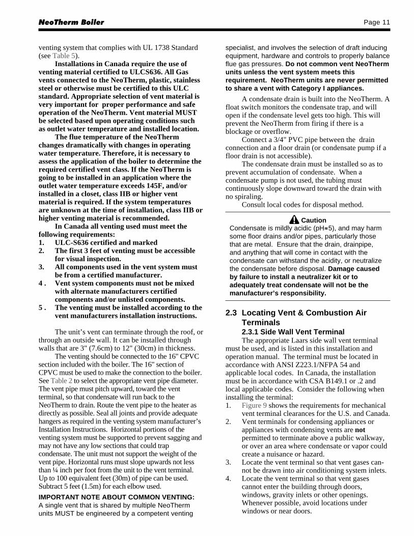
LAARS Heating SystemsPage 20
Figure 15. Hydronic Piping — Multiple Boilers, Reverse Return, Multi-Temp Zones (zoning with circulators).

NeoTherm Boiler Page 21
SECTION 5.Electrical Connections
WARNINGThe appliance must be electrically grounded inaccordance with the requirements of the authorityhaving jurisdiction or, in the absence of suchrequirements, with the latest edition of the NationalElectrical Code, ANSI/NFPA 70, in the U.S. and withlatest edition of CSA C22.1 Canadian Electrical Code,Part 1, in Canada. Do not rely on the gas or water pipingto ground the metal parts of the boiler. Plastic pipe ordielectric unions may isolate the boiler electrically.Service and maintenance personnel, who work on oraround the boiler, may be standing on wet floors andcould be electrocuted by an ungrounded boiler.Electrocution can result in severe injury or death.
Single pole switches, including those of safetycontrols and protective devices must not be wired in agrounded line.
All electrical connections are made on the terminalblocks that are located inside the control panel.NOTE: All internal electrical components have beenprewired. No attempt should be made to connectelectrical wires to any other location except the terminalblocks.
Wiring connections are shown in Figure 20.
5.1 Main PowerConnect a minimum 15A fused, 120-volt supply to
the main power switch (hot leg is connected directly toswitch). Neutral leg is connected directly to the whitewire. Ground wire can be connected to the groundinglug in the box.
5.2 Control FeaturesThe NeoTherm boiler control is a versatile control
that interfaces with a user display. The user displayallows access to many features of the control for setup,diagnostics and operation. There are three menu
MENU ITEM
Outlet water temperature Displays the current outlet watertemperature and allows the setpointto be adjusted.
Inlet water temperature Displays the current inlet watertemperature
Delta T Displays the current Temperaturerise across the heat exchanger
DHW water temperature Displays the current DHWtemperature and allows the setpointto be adjusted
Stack Temperature Displays the current stacktemperature
Outdoor Temperature Displays the current Outdoor airtemperature
Firing Rate Displays an indicator of the currentfiring rate based upon fan RPM. Theactual firing rate may vary.
Table 10. User Mode Menu Structure.
structures to choose from, USERUSERUSERUSERUSER mode, SETUPSETUPSETUPSETUPSETUP mode, andDIAGNOSTICDIAGNOSTICDIAGNOSTICDIAGNOSTICDIAGNOSTIC mode. Each mode will give the user access todifferent types of information. The menus are accessedby using the buttons located on the display.
5.2.1 User ModeUSERUSERUSERUSERUSER mode is the home screen shown on the
control. To navigate from item to item within USERUSERUSERUSERUSERmode press the NEXT button. If a menu that is useradjustable is selected, such as outlet or DHW the UP orDOWN arrows can be used to adjust the temperaturesetpoint. Once the correct value is selected the DONEbutton can be pressed to select the adjusted values. TheUSERUSERUSERUSERUSER mode menu structure and information that isavailable is shown in Table 10.
5.2.1.1 Temperature Control PointAdjustment
To adjust the temperature control point, confirmthe display is in USERUSERUSERUSERUSER mode and the outlet temperature isbeing displayed. Press the UP or DOWN arrow to adjustthe control point temperature. The control pointtemperature is measured at the outlet of the heatexchanger. When making adjustments make sure thecontrol point is set far enough away from the high limitto keep the temperature rise of the heat exchanger fromcausing nuisance high limit tripping problems.
5.2.1.2 Domestic Hot Water Control PointAdjustment
To adjust the DHW temperature control point,confirm the display is in USERUSERUSERUSERUSER mode. Scroll through themenu structure using the NEXT button until the currentDHW temperature is being displayed. Use the UP orDOWN arrow to adjust the setpoint to the desired value.Press the DONE button when complete.
5.2.2 Setup ModeSETUPSETUPSETUPSETUPSETUP mode is accessed by holding the UP and
DOWN arrow keys simultaneously for 3 seconds. SETUPSETUPSETUPSETUPSETUPmode allows the parameters listed in Table11 to beadjusted by using the NEXT button to select the
Figure 16. Control Buttons on User Interface.

LAARS Heating SystemsPage 22
parameter to be adjusted and then the UP or DOWNarrow keys to make the adjustment. When theadjustment is complete press the DONE (or NEXT) buttonto move to next menu item.
5.2.2.1 Adjusting the TemperatureDisplay Units in °F or °C
Confirm the display is in SETUPSETUPSETUPSETUPSETUP mode. Scroll to theF/CF/CF/CF/CF/C menu. Press the UP or DOWN arrow to adjustbetween Fahrenheit and Celsius. Press the DONE keywhen complete.
5.2.2.2 Adjusting the Outdoor ResetOn or Off
Confirm the display is in SETUPSETUPSETUPSETUPSETUP mode. Scroll to theLBTHODLODLBTHODLODLBTHODLODLBTHODLODLBTHODLOD menu using the NEXT button. Use the UP orDOWN arrows to select on or off. When outdoor reset isturned on, three new menus will be added to setup mode.
5.2.2.3 Adjusting Low BoilerTemperature Setpoint
Confirm the display is in SETUPSETUPSETUPSETUPSETUP mode. Scroll to theLBTLBTLBTLBTLBT menu. Use the UP or DOWN arrows to scroll to theminimum water temperature desired during outdoor reset.
5.2.2.4 Adjusting High OutdoorTemperature Setpoint
Confirm the display is in SETUPSETUPSETUPSETUPSETUP mode. Scroll to theHODHODHODHODHOD menu. Use the UP or DOWN arrows to scroll to themaximum outdoor temperature the reset curve will useto equate to the minimum water temperature.
5.2.2.5 Adjusting Low OutdoorTemperature Setpoint
Confirm the display is in SETUPSETUPSETUPSETUPSETUP mode. Scroll to theLODLODLODLODLOD menu. Use the UP or DOWN arrows to scroll to theminimum outdoor temperature the reset curve will use
to equate to the maximum water temperature.5.2.2.6 Anti Short Cycle TimeConfirm the display is in SETUPSETUPSETUPSETUPSETUP mode. Scroll to the
ASCASCASCASCASC menu. Use the UP or DOWN arrows to adjust thetime for the anti short cycle period. The numbersdisplayed are in minutes of delay. The anti short cycletime creates a delay for the specified period of timebetween the completion of a call for heat and when thenext call for heat may occur.
5.2.3 Diagnostic ModeDIAGNOSTICDIAGNOSTICDIAGNOSTICDIAGNOSTICDIAGNOSTIC mode is accessed by holding the NEXT
button for 3 seconds. DIAGNOSTICDIAGNOSTICDIAGNOSTICDIAGNOSTICDIAGNOSTIC mode allows the user tomonitor and control the items shown in Table 12. Toscroll through the menu structure use the NEXT button.When a value that is adjustable has been selected the UPor DOWN arrow keys may be used to adjust the setpoint.When adjustments are complete press the DONE button.
5.2.3.1 High Limit SettingThe appliance high limit sensor is located on the
outlet of the boiler. The sensor is a dual element sensorthat is limit rated. This sensor must be replaced withLaars original equipment parts only. The high limit setpoint is not adjustable.
5.2.3.2 DHW Limit SettingThe DHW maximum temperature setting has been
adjusted at the factory, and can be viewed by enteringthe DIAGNOSTICDIAGNOSTICDIAGNOSTICDIAGNOSTICDIAGNOSTIC mode and scrolling to the DHWDHWDHWDHWDHW menu.Once in the DHWDHWDHWDHWDHW menu, the maximum temperature willbe displayed.
WARNINGThe DHW sensor is NOT a limit rated device. An anti-scald device MUST be installed to prevent exces-sively hot water from reaching the end user. Failureto install an anti-scald device may lead to propertydamage, personal injury or death.
MENU ITEM DEFINITION
Fahrenheit / Selects the temperature units beingCelsius displayedLBTHODLOD Turn outdoor reset on or offLBT Low boiler temperature setpoint.
Display and set the lowest boiler watertemperature desired during outdoor reset
HOD High outdoor temperature setpoint.Display the current setpoint and allow foradjustment of the high outdoor temperaturesetpoint for the reset curve.
LOD Low outdoor temperature setpoint.Display the current setpoint andallow for adjustment of the Low outdoortemperature setpoint for the reset curve
RMT Remote firing control.Set the Remote Firing Control ON or OFF.This allows the use of a external analogsignal to control boiler modulation
RMT ADR RMT Address. Display the currentModbus address and allows for adjustmentof the address.
ASC Anti short cycle. Display the current AntiShort cycle time and allows for adjustmentusing the up and down arrows.
Table 11. Setup Mode Parameters.
MENU ITEM DESCRIPTION
mA Display the flame sense signalAlert codes Displays the current alert codeLockout code Displays the current lockout codeOutlet Limit Displays outlet temperature limitDHW limit Displays Domestic Hot Water limit settingStack Limit Displays Stack limit settingMin. firing rate Displays the minimum firing rate allowedMin. forced Allows the user to force the boiler to fire atfiring rate the minimum firing rateMax forced Allows the user to force the boiler to fire atfiring rate the maximum firing rateRate indicator Displays a indicator of the firing rate based
off of the fan RPM. Actual firing rate mayvary depending upon setup.
Table 12. Diagnostic Mode Menu Structure.

NeoTherm Boiler Page 23
5.3 Pump ConnectionsThe boiler pump is wired at the factory (pump
mounted models only). The NeoTherm Controlenergizes the pump upon a call for heat. Once the callfor heat is satisfied the pump will remain on for thedefined pump overrun time.
The system pump connections are located onTerminal Block 5 in the control panel (see Figure 17).The system pump contacts are rated for 120Vac, 7.4amps. To use the contacts power must be supplied onone terminal. The other terminal wired to the pump or acontact controlling the pump.
The DHW pump connections are located onTerminal Block 5 in the control panel. The DHW pumpcontacts are rated for 120Vac, 7.4 amps. To use thecontacts power must be supplied on one terminal. Theother terminal wired to the pump or a contactcontrolling the pump.
5.4 Temperature ControlThe NeoTherm temperature control measures the
temperature on the outlet sensor, measuring the supplywater temperature. Set the control setpoint for thedesired supply temperature.
The manual reset high limit is located on the outletof the NeoTherm. The manual reset limit temperaturemust be set a minimum of 10° higher than the controlpoint to avoid nuissance high limit tripping issues.
5.5 Temperature Control - Indirect TankFor indirect domestic hot water applications a
DHW sensor or mechanical aquastat may be used todetermine the domestic load call. To do this, the sensoror aquastat should be connected to Terminal block 6
connections labeled "DHW temp sensor". The sensor isa dual element sensor. The Laars sensor is the onlysensor that can be used with this controller. To connectan aquastat use the middle and far right connector onTerminal block 6, connections labeled "DHW tempsensor". Once a sensor or switch is installed, the callshould be "Audodetected" by the control.
5.6 Outdoor Reset OperationOutdoor reset varies the control point setpoint
based on the outdoor temperature. The reset functionworks as shown in Figure 18. When the Outdoor airtemperature reaches the High Outdoor temperaturesetpoint (HOD), the control point is adjusted to the LowBoiler temperature setpoint (LBT). When the outdoorair temperature reaches the Low Outdoor temperature(LOD) setpoint, the control setpoint is adjusted to theCH setpoint temperature. To access the LOD, HOD andLBT variables, refer to Sections 5.2.2.3 through 5.2.2.5.To access CH setpoint, refer to Section 5.2.1.1.
The outdoor air temperature sensor must beconnected to terminal block 7 in the control panel. Theconnection points are labeled “outdoor temp sen.” Thesensor is not polarity sensitive, so the wires may beconnected to either terminal.
5.7 External Control ConnectionsNeoTherm units are built with a terminal strip to
allow the NeoTherm to receive a 4-20mA modulatingsignal from an external controller (such as a buildingautomation system or multiple boiler control).
When a 4-20mA signal is supplied to NeoTherm,it will modulate according to the signal supplied.
The Brown/White wire is for signal (+) and the
Figure 17. Control Panel Layout.

LAARS Heating SystemsPage 24
Brown wire is for signal (–).A call for heat signal MUST also be connected to
the field interlock terminal strip on the NeoTherm(shown in Figures 17 and 20).
The NeoTherm unit will modulate between 4mAand 20mA (for 20% and 100%, respectively).Important Note: DO NOT MAKE/BREAK NEOTHERMLINE VOLTAGE TO SIGNAL CALL FOR HEAT. A “callfor heat / end call for heat” MUST be connected to thefield interlock terminals. The NeoTherm does notrecognize 4mA as a signal to shut off. If the call for heatis not connected between the field interlock terminals,the NeoTherm will remain in low fire when it sees 4mAas a modulating signal.
CautionNeoTherm supply voltage must not be disengaged,except for service or isolation, or unless otherwiseinstructed by procedures outlined in this manual. Tosignal a call for heat, use the 24V field-interlock, asshown in the wiring diagram(s).Some NeoTherm components are designed to haveconstant voltage during normal operation. If theNeoTherm's supply voltage is toggled as a call forheat signal, premature failure of these componentsmay result.
5.8 Wiring Diagram (see Figures 19 and 20)
CautionLabel all wires prior to disconnection when servicingcontrols. Wiring errors can cause improper anddangerous operation. Verify proper operation afterservicing
Figure 19. Ladder Diagram.Figure 18. Outdoor Reset Setpoint Temperatures.

NeoTherm Boiler Page 25
Figure 20. Wiring Diagram (all sizes).

LAARS Heating SystemsPage 26
water valve.13. Check gauge for correct water pressure and also
check water level in the system. If the heightindicated above the boiler insures that water is atthe highest point in the circulating loop, then thesystem is ready for operation.
14. Refer to local codes and the make-up water valvemanufacturer’s instructions as to whether themake-up water valve should be left open or closed.
15. After placing the unit in operation, the ignitionsystem safety shutoff device must be tested. First,shut off the manual gas valve, and call the unit forheat. Main gas terminals will be energized,attempting to light, for four (4) seconds, and thenwill de-energize. The unit will go into lockoutafter the required number of trial for ignitionperiods. Second, turn the power off, press themanual reset button on the boiler control, or theuser display, open the manual gas valve and allowthe unit to light. While the unit is operating, closethe manual gas valve and ensure that power to themain gas valve has been cut.
16. Within three (3) days of start-up, recheck all airbleeders and the expansion tank as described inSteps 4 and 8 above.
Important Note: The installer is responsible foridentifying to the owner/operator the location of allemergency shutoff devices.
WARNINGDo not use this appliance if any part has been underwater. Immediately call a qualified service technicianto inspect the applianceand to replace any part of the control system and anygas control that may have beenunder water.
6.2 Operating the Burner and Set UpThe NeoTherm modulating appliance utilizes an
advanced, state-of-the-art design. The setup must bechecked before the unit is put in operation. Problemssuch as failure to start, rough ignition, strong exhaustodors, etc. can be due to improper setup. Damage to theboiler resulting from improper setup is not covered bythe limited warranty.
6.2.1 Burner OperationREQUIRED TOOLS: differential pressure gauge
capable of reading negative 0.01 inches W.C.(0.002kPa), screw drivers, torx bits, combustibleanalyzer.1. Using this manual, make sure the installation is
complete and in full compliance with theinstructions and all local codes.
2. Determine that the appliance and system are filledwith water and all air has been bled from both.
SECTION 6.Operating Instructions
6.1 Filling the Boiler System1. Ensure the system is fully connected. Close all
bleeding devices and open make-up water valve.Allow system to fill slowly.
2. If make-up water pump is employed, adjustpressure switch on pumping system to provide aminimum of 12 psi (81.8 kPa) at the highest pointin the heating loop.
3. If a water pressure regulator is provided on themake-up water line, adjust the pressure regulatorto provide at least 12 psi (81.8 kPa) at the highestpoint in the heating loop.
4. Open bleeding devices on all radiation units at thehigh points in the piping throughout the system,unless automatic air bleeders are provided at suchpoints.Note that there is an air bleed located on the leftside of the unit, on top of the water manifold.
5. Cycle the boiler pump on and off 10 times, 10seconds on and 10 seconds off to remove all airfrom the heat exchanger. Then run system andappliance pump for a minimum of 30 minutes withthe gas shut off.
WARNINGFailure to remove all air from the heat exchangercould lead to property damage, severe injury or death.
6. Open all strainers in the circulating system, checkflow switch operation (if equipped), and check fordebris. If debris is present, clean out to ensureproper circulation.
7. Recheck all air bleeders as described in Step 4.8. Check liquid level in expansion tank. With the
system full of water and under normal operatingpressure, the level of water in the expansion tankshould not exceed ¼ of the total, with the balancefilled with air.
9. Start up boiler according to the procedure in thismanual. Operate the entire system, including thepump, boiler, and radiation units for one (1) hour.
10. Recheck the water level in the expansion tank. Ifthe water level exceeds ¼ of the volume of theexpansion tank, open the tank drain, and drain tothat level.
11. Shut down the entire system and vent all radiationunits and high points in the system piping, asdescribed in Step 4.
12. Close make-up water valve and check strainer inpressure reducing valve for sediment or debrisfrom the make-up water line. Reopen make-up
NeoTherm Boiler Page 27
Open all valves.3. Observe all warnings on the Operating Instructions
label and turn on gas and electrical power toappliance.
4. The NeoTherm will enter the start sequence. Theblower and pump will energize for pre-purge, thenthe ignition sequence starts. After all safetydevices are verified, the gas valve opens. Ifignition doesn’t occur, turn off the NeoTherm,check that there is proper gas supply. Wait 5minutes and start the unit again.
5. Turn the NeoTherm on.
6. After placing the appliance in operation, theBurner Safety Shutoff Device must be tested.To test:(a) Close gas shutoff valve with burner
operating.(b) The flame will go out and blower will
continue to run for the post purge cycle. Oneor three additional attempts to light willfollow including pre-purge, ignitor on, valve/flame on and post purge. Ignition will notoccur as the gas is off. The ignition controlwill lockout.
(c) Open gas shutoff valve. Reset the boilercontrol by pressing the RESET button on thecontrol or on the display. Restart theappliance. The ignition sequence will startagain and the burner will start. The appliancewill return to its previous mode of operation.
CautionShould any odor of gas be detected, or if the gasburner does not appear to be functioning in a normalmanner, CLOSE MAIN SHUTOFF VALVE. Do notshut off switch. Contact your heating contractor, gascompany, or factory representative.
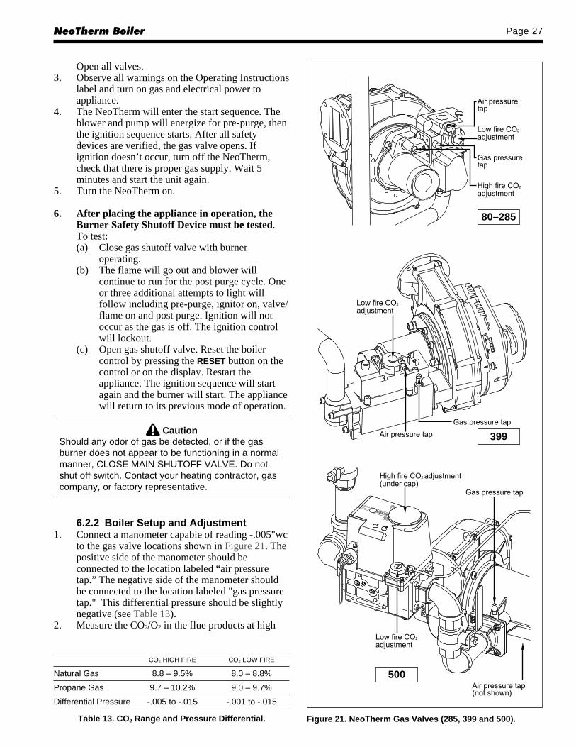
6.2.2 Boiler Setup and Adjustment1. Connect a manometer capable of reading -.005"wc
to the gas valve locations shown in Figure 21. Thepositive side of the manometer should beconnected to the location labeled “air pressuretap.” The negative side of the manometer shouldbe connected to the location labeled "gas pressuretap." This differential pressure should be slightlynegative (see Table 13).
2. Measure the CO2/O2 in the flue products at high
CO2 HIGH FIRE CO2 LOW FIRE
Natural Gas 8.8 – 9.5% 8.0 – 8.8%
Propane Gas 9.7 – 10.2% 9.0 – 9.7%
Differential Pressure -.005 to -.015 -.001 to -.015
Table 13. CO2 Range and Pressure Differential. Figure 21. NeoTherm Gas Valves (285, 399 and 500).
399
80–285
500

LAARS Heating SystemsPage 28
fire. The NeoTherm can be forced to high fire toallow for easier setup. Refer to Section 5.2.3 forinstructions on how to access the forced rate menu.The CO2 readings should be between the valuesshown in Table 13. If the CO2 is not within therange shown, adjustments may be made. To adjustthe high fire CO2, locate the high fire adjusterscrew according to the appropriate figure. Slowlymake adjustments in 1/16 of a revolutionincrements until the CO2 is within the rangeidentified.NOTE: NeoTherm 399 does not have a high fireadjustment.
3. Measure the CO2/O2 in the flue products at lowfire. The NeoTherm can be forced to low fire toallow for easier setup. Refer to Section 5.2.3 forinstructions on how to access the forced rate menu.The CO2 readings should be between the valuesshown in Table 13. If the CO2 is not within therange shown, adjustments may be made. To adjustthe low fire CO2, locate the low fire adjuster screwaccording to the appropriate figure. Slowly makeadjustments in 1/16 of a revolution incrementsuntil the CO2 is within the range identified.
4. Repeat steps 2 and 3 to confirm that the CO2
ranges are within the required ranges. Adjust ifnecessary.
5. Confirm that the differential pressure is still withinthe appropriate range.
6. If any of the measurements cannot be adjusted tothe specified ranges or the CO levels are above150ppm when adjusted please consult the factoryfor further information.
7. Remove the differential pressure gauge from theair and gas pressure taps making sure to close allports after the gauge has been removed.
WARNINGImproper adjustment may lead to poor combustionquality, increasing the amount of carbon monoxideproduced. Excessive carbon monoxide levels maylead to personal injury or death.
6.3 Shutting Down the NeoTherm1. Turn off the main electrical disconnect switch.2. Close all manual gas valves.3. If freezing is anticipated, drain the NeoTherm and
be sure to also protect building piping fromfreezing. All water must be removed from heatexchanger or damage from freezing may occur.
This step to be performed by a qualified service person.
6.4 To Restart the NeoThermIf drained, follow Section 6.1 in this manual for
proper filling and purging.1. Turn off the main electrical disconnect switch.
2. Close all manual gas valves.3. WAIT FIVE (5) MINUTES.4. Set the aquastat or thermostat to its lowest setting.5. Open all manual gas valves.6. Reset all safety switches (pressure switch, manual
reset high limit, etc.).7. Set the temperature controller to the desired
temperature setting and switch on electrical power.8. Burner will go through a prepurge period and
ignitor warm-up period, followed by ignition.
SECTION 7.Maintenance
WARNINGDisconnect all power to the appliance beforeattempting any service to the appliance. Contact withelectricity can result in severe injury or death.
7.1 System Maintenance1. Lubricate the system water-circulating pump, if
required, per the instructions on the pump.2. If a strainer is employed in a pressure reducing
valve or the piping, clean it every six months.3. Inspect the venting system for obstruction or
leakage at least once a year. Periodically clean thescreens in the vent terminal and combustion airterminal (when used).
4. Keep the appliance area clear and free fromcombustible materials, gasoline, and otherflammable vapors and liquids.
5. If the appliance is not going to be used forextended periods in locations where freezingnormally occurs, it should be isolated from thesystem and completely drained of all water.
6. Low water cutoffs, if installed, should be checkedevery 6 months. Float type low water cutoffsshould be flushed periodically.
7. Inspect and clean the condensate collection, floatswitch and disposal system yearly.
8. When a means is provided to neutralizecondensate, ensure that the condensate is beingneutralized properly.
9. Inspect flue passages, and clean with brushes/vacuums, if necessary. Sooting in flue passagesindicates improper combustion. Determine thecause and correct.
10. Inspect the vent system and air intake system, andensure that all joints are sealed properly. If jointsneed to be resealed, completely remove existingsealing material, and clean with alcohol. Applynew sealing material, and re-assemble.

NeoTherm Boiler Page 29
7.2 Appliance Maintenance andComponent DescriptionUse only genuine LAARS replacement parts.
CautionLabel all wires prior to disconnection when servicingcontrols. Wiring errors can cause improper anddangerous operation. Verify proper operation afterservicing.
The gas and electric controls on the appliance areengineered for long life and dependable operation, butthe safety of the equipment depends on their properfunctioning. It is strongly recommended that a qualifiedservice technician inspect the basic items listed belowevery year.
a. Appliance controlb. Automatic gas valvec. Pressure switchesd. Blower
e. Pumpf. Flow switchg. Low water cutoff
7.2.1 BurnerCheck the burner for debris. Remove the blower
arm assembly to access the burner. Remove the 4 boltsconnecting the blower to the arm (see Figure 22).Remove the 5 bolts, which hold the burner arm in place.Pull burner up and out. Clean burner, if necessary, byblowing compressed air from the outside of the burnerinto the center of the burner, and wipe the inside of theburner clean with glass cleaner. A dirty burner may bean indication of improper combustion or dirtycombustion air. Determine the cause, and correct. Ifdamaged, replace the burner gasket when replacing theburner.NOTE: When installing the burner, make sure theflange is aligned with the mating surface, as each iskeyed to control fit.
Figure 22. Burner Service.
LAARS Heating SystemsPage 30
7.2.2 Modulating Gas Valve / VenturiThe modulating gas valve consists of a valve body
that incorporates the ON/OFF gas flow control and anegative pressure regulator. It provides the air/gas ratiocontrol in combination with the venturi to the unit. It isdesigned to operate with gas supply pressure between 4and 13 inches w.c.. To remove the gas valve and orventuri. Shut off the 120 Volt power supply to theboiler. Turn off all manual gas valves connecting theboiler to the main gas supply line. Remove the frontdoor of the boiler to gain access to the gas valve andventuri. Disconnect the four (4) flange bolts connectingthe gas manifold pipe to the gas valve. Remove theelectrical connections to the gas valve. Remove the boltsconnecting the venturi flange to the blower. This allowsthe entire gas valve/venturi assembly to be removed asan assembly to facilitate inspection and cleaning.
After the valve has been removed, reassemble inreverse order making sure to include all gaskets and O-rings. Turn on the manual gas valves and check for gasleaks. Turn on the 120 Volt power. Place the unit inoperation following the instructions in Section 6.2.Once the boiler is operating check for leaks again andconfirm all fasteners are tight.
Check appliance setup according to Section 6.2.
7.2.3 Appliance ControlThe NeoTherm appliance control is an integrated
control that incorporates the manual reset high limitcontrol, the operating temperature control, modulatingcontrol, ignition control, outdoor reset control, pumpcontrol and many other features. If any of these featuresare thought to be defective, please consult the factoryfor proper trouble shooting practices prior to replacingthe control. If control replacement is required, turn offall power to the appliance. Shut all manual gas valves tothe appliance. Remove the front door to the applianceand the control panel plastic bezel. Remove all wireconnections from the control board. The control boardconnections are keyed to only allow connection in theproper location, but proper handling techniques shouldbe used to avoid damage to the wiring or connectors. Toremove the control push in on the two tabs on the leftside of the board to unlatch the clips from the controlpanel. Rotate the control around the fastening points onthe right side of the control to remove the hooks fromthe control panel. To replace the control repeat the stepsabove in the reverse order making sure to connect allwires in the proper location. Place the appliance inoperation following the steps outlined in Section 6.2.
7.2.4 Ignitor AssemblyThe ignitor assembly is a two rod system that
consists of a ground rod and a sense rod. To remove theignitor assembly, shut off the 120 Volt power supply tothe appliance. Turn off all manual gas valves connectingthe appliance to the main gas supply line. Remove thefront door of the boiler to gain access to the ignitor
assembly. Remove the two wires connected to theassembly. Then remove the two bolts connecting theignitor assembly to the burner door. Remove andreplace the old ignitor assembly gasket. Reinstall a newignitor assembly in the reverse order if the old assemblyis determined defective. Replace gasket if necessary.
7.2.5 Flame SensorThe flame sensor is a single rod system. To replace
the flame sensor electrode, shut off the 120 Volt powersupply to the boiler. Turn off all manual gas valvesconnecting the boiler to the main gas supply line.Remove the front door of the boiler to gain access to theflame sensor electrode. Remove the flame sensor wirefrom the electrode. Remove the two bolts fastening theelectrode to the burner doors. Remove and replace theold flame sensor gasket. Reinstall a new flame sensorelectrode in the reverse order if the old electrode isdetermined defective.
CautionIgniters and sensors get hot and
can cause burns or injury.
7.2.6 TransformersThere are various transformers used on the
NeoTherm units. Be sure to replace the transformerswith factory parts. These transformers are not capable ofsupplying control voltage for external devices such aszone valves, which must have their own separate powersupply. Should a transformer need replacing, shut offthe 120 Volt power. Unplug the transformer wires,remove the mounting screws and remove thetransformer. Replace transformer in the reverse order.
7.2.7 BlowerThe combustion air blower is a high-pressure
centrifugal blower with a variable speed motor. Thespeed of the motor is determined by the control logic.The 120 Volt current remains on to the blower at alltimes. If a blower change is required, turn off the 120Volt power and gas supply to the unit. Take the frontpanel off. Disconnect the 120 Volt and control signalconnections from the blower. Disconnect the boltsconnecting the venturi to the blower housing.Disconnect the fan outlet bolts from the burner doorblower arm. If the fan is determined to be defectivereplace the existing fan with a new one reversing thesteps above. Make sure to install all of the required O-rings and gaskets between the blower arm and theblower and blower face and venturi flange.
7.2.8 Heat Exchanger CoilsBlack carbon soot buildup on the external surfaces
of the heat exchanger is caused by one or more of thefollowing; incomplete combustion, combustion air
NeoTherm Boiler Page 31
problems, venting problems and heater short cycling.Soot buildup or other debris on the heat exchanger mayrestrict the flue passages.
If black carbon soot buildup on the heat exchangeris suspected, disconnect electrical supply to the unit,and turn off the gas supply by closing the manual gasvalve on the unit. Access the heat exchanger through theburner door at the front of the boiler, and inspect thetubing using a flashlight. If there is a buildup of blackcarbon soot or other debris on the heat exchanger, cleanper the following:
CautionBlack carbon soot buildup on a dirty heat exchangercan be ignited by a random spark or flame. Toprevent this from happening, dampen the sootdeposits with a wet brush or fine water spray beforeservicing the heat exchanger.
1. Shut off the 120 Volt power supply to the boiler2. Turn off all manual gas valves connecting the
boiler to the main gas supply line.3. For NT 500 models only (all other sizes please
skip to step four). NT 500 models will require thegas valve to be removed in order to remove theburner door. To do this, remove the wireconnections from the gas valve. Remove the flangebolts from the gas supply pipe connected to the gasvalve (1B). Remove the flange bolts connectingthe gas train to the venturi (1A). Remove the gastrain assembly keeping gaskets and o-rings.
4. Remove the four bolts connecting the blowerflange to the burner door arm.
5. Remove the nuts located on the outside diameterof the burner door to the heat exchanger.
6. Remove the burner door/burner assembly from theheat exchanger.
7. Disconnect the condensate drain line.8. Attach a longer hose to drain and run to a bucket.9. Clean the heat exchanger by brushing light
accumulations of soot and debris. Use a brush withsoft bristle (non metal) to avoid damaging thesurface of the heat exchanger tubes.
10. Once the tubes have been brushed clean rinse thetubes and combustion chamber with a smallamount of water to rinse all of the debris out of thebottom of the flue collector and into the longercondensate trap line, which is being diverted into aseparate container.
NOTE: The Warranty does not cover damage causedby lack of required maintenance, lack of water flow,or improper operating practices.
WARNINGFailure to rinse the debris from the heat exchangerand temporary drain line may lead to clogged
condensate lines, traps and neutralizers. Condensatepumps (if used) may also be damaged from thedebris left behind, possibly causing property damage.
11. Install all components removed in the reverseorder to place the appliance back in operation.Make sure all gaskets are in place as componentsare installed. Replace any damaged gaskets. DoNOT reuse damaged gaskets.
12. Place the appliance in operation according toSection 6.2 checking all gas connections for leaks.Confirm all fasteners are tight.
7.2.9 Gas Pressure Switches (optional)The high and low gas pressure switches are 24V
manual reset switches that act to cut power to the gasvalves if the gas pressure is too low or too high forproper operation. The gas pressure switches used areintegrally vent limited, and do not require venting toatmosphere. To remove a switch, remove the screw onthe plastic housing and pull the clear cover off.Disconnect the two wires from the screw terminals.Twist the switch off the pipe nipple. Reassemble inreverse order. For natural gas, set the low gas pressureswitch to 3" w.c. For propane, set the low gas pressureswitch to 5" w.c. For natural and propane, set the highgas pressure switch to 14".
SECTION 8.Trouble Shooting
8.1 Sequence of OperationThe NeoTherm appliance is a cold start appliance
that should start only on a call for heat from a tankaquastat, room thermostat, zone valve end switch orother space temperature control device.1. Upon a call for heat: (a) the internal pump and
system pump will start; (b) the blower will begin a30 second pre-purge.
2. Following the prepurge cycle the direct sparkignition will spark and will begin a 4 second trialfor ignition. The unit is allowed one or threeignition retries.
3. The gas valve will then be energized and a reducedrate ignition will occur. The unit will remain in areduced rate start-up period for several seconds.
4. After the reduced rate start time is over, the unitwill be in normal operation. Firing rate willmodulate based on the heating load via thetemperature controller settings and readings.
5. When the call for heat is complete, or the unit reachesits setpoint temperature, the gas valve will close, andthe fan will continue to run for its 20 second post-purge. If a pump delay time is used, the pump willcontinue to run for the specified amount of time(adjustable from 0.1 to 10 minutes).

LAARS Heating SystemsPage 32
CODE # ERROR NAME ERROR DESCRIPTION POSSIBLE SOLUTIONS
109 Ignition failed Failed to prove flame Main gas supply off or low pressure, safety interrupt,and proceed to RUN mode malfunctioning gas valve
27 Internal error: flame rod Flame rod grounded Faulty wiring, sensor probe grounded, material build upshort to ground on sensor probe
63 LCI off Safety chain interrupt Check flow switch, additional high limit, LWCO, gaspressure switches, condensate level switch for proper
operation137 ILK failed to close No power at ILK Check J5 pin 1 for power - if no power, confirm all
safeties are operating correctly69 Outlet high limit High limit tripped. Determine cause of high temperature limit trip. Low/no
water flow, manual valves closed, improper settings92 Outlet sensor fault Outlet sensor error Check wiring and sensor resistance to confirm
connections and sensor operation122 Light off proving rate failed Fan speed at ignition Consult factory
out of tolerance80 DHW limit DHW high limit reached Check pump operation and time delay, manual valves93 DHW sensor fault DHW sensor open or shorted Check wiring and sensor resistance to confirm
connections and sensor operation96 OAT temperature sensor fault Outdoor Air Temperature Check wiring to sensor and sensor to determine if sensor
sensor faulty is open or shorted
Table 14. Error Codes.
8.2 Short CyclingBecause the NeoTherm is a modulating boiler, and
its input will decrease when there is a reduction inheating load, short cycling is greatly reduced. If theheating load drops below the minimum input of theboiler for an extended period, the boiler will have atendency to short cycle. This can be a symptom ofimproper control strategy or setpoints, or a loaddistribution problem. The NeoTherm control has a built-in anti-short cycle (ASC) feature. The ASC is a timedsetting that will delay the boiler start for a specifiedtime after one call for heat is completed. The ASC timemay be adjusted as desired (see Sections 5.2.2 and5.2.2.6 for more information).
8.3 Error Codes - See Table 14.
SECTION 9.Replacement PartsUse only genuine LAARS replacement parts.
9.1 General InformationTo order or purchase parts for the LAARS
NeoTherm, contact your nearest LAARS dealer ordistributor. If they cannot supply you with what youneed, contact Customer Service (see back cover foraddress, telephone and fax numbers).

NeoTherm Boiler Page 33
9.2
Part
s Li
stIT
EMD
ESC
RIP
TIO
NSI
ZE 8
0SI
ZE 1
05SI
ZE 1
50SI
ZE 2
10SI
ZE 2
85SI
ZE 3
99SI
ZE 5
00
Jack
et C
ompo
nent
s, S
ee F
igur
e 25
1Fr
ont P
anel
Ass
embl
yR
50D
3200
R50
D32
00R
50D
3200
R50
D32
00R
50D
3200
R50
D32
00R
50D
3200
2Fr
ont P
anel
Han
dle
R50
D32
04R
50D
3204
R50
D32
04R
50D
3204
R50
D32
04R
50D
3204
R50
D32
043
Rea
r Pan
elR
50D
3101
R50
D31
01R
50D
3101
R50
D31
01R
50D
3101
R50
D31
01R
50D
3101
4Le
ft S
ide
Pan
elR
15D
3002
R15
D30
02R
15D
3002
R30
D30
02R
30D
3002
R40
D30
02R
50D
3002
5R
ight
Sid
e P
anel
R15
D30
01R
15D
3001
R15
D30
01R
30D
3001
R30
D30
01R
40D
3001
R50
D30
016
Left
Top
Pan
elR
8D33
03R
10D
3303
R15
D33
03R
21D
3303
R30
D33
03R
40D
3303
R50
D33
037
Mid
dle
Top
Pan
elR
8D33
02R
10D
3302
R15
D33
02R
21D
3302
R30
D33
02R
40D
3302
R50
D33
028
Rig
ht T
op P
anel
R8D
3301
R10
D33
01R
15D
3301
R21
D33
01R
30D
3301
R40
D33
01R
50D
3301
9Ja
cket
Ang
le S
uppo
rtR
8D31
02 (R
H)
R15
D31
02R
15D
3102
R30
D31
02R
30D
3102
R40
D31
02R
50D
3102
R15
D31
02 (L
H)
(2)
(2)
(2)
(2)
(2)
(2)
10Ja
cket
Sup
port
Left
Sta
nchi
onR
50D
3003
R50
D30
03R
50D
3003
R50
D30
03R
50D
3003
R50
D30
03R
50D
3003
11Ja
cket
Sup
port
Rig
ht S
tanc
hion
R50
D30
04R
50D
3004
R50
D30
04R
50D
3004
R50
D30
04R
50D
3004
R50
D30
0412
Fron
t Bez
elR
50D
7101
R50
D71
01R
50D
7101
R50
D71
01R
50D
7101
R50
D71
01R
50D
7101
Inte
rnal
Com
pone
nts
– Se
e Fi
gure
26
20B
ase
Ass
embl
y15
D11
0015
D11
0015
D11
00R
30D
1100
R30
D11
00R
40D
1100
R50
D11
0021
Left
Rea
r Sup
port
Sta
nchi
onR
50D
1001
R50
D10
01R
50D
1001
R50
D10
01R
50D
1001
R50
D10
01R
50D
1001
22Le
ft Fr
ont/R
ight
Rea
r Sup
port
Sta
nchi
onR
50R
1002
R50
R10
02R
50R
1002
R50
R10
02R
50D
1002
R50
D10
02R
50D
1002
(2)
(2)
(2)
23C
antil
ever
ed B
ase
Sta
nchi
onR
15D
1002
R15
D10
02R
15D
1002
R40
D10
01R
40D
1001
R40
D10
01—
24Fr
ont/R
ear S
tanc
hion
Bra
ceR
50D
1005
R50
D10
05R
50D
1005
R20
D10
06R
50D
1005
R50
D10
05R
50D
1005
(2)
25M
ount
ing
Rai
lR
15D
1004
R15
D10
04R
15D
1004
R30
D10
04R
30D
1004
R30
D10
04R
50D
1004
(2)
(2)
(2)
(2)
26R
ight
Fro
nt S
uppo
rt S
tanc
hion
——
——
——
R50
D10
0327
Con
dens
ate
Trap
Ass
embl
yR
20D
4020
R20
D40
20R
20D
4020
R20
D40
20R
50D
4020
R50
D40
20R
50D
4020
28H
eat E
xcha
nger
Rai
l Clip
R50
D10
06R
50D
1006
R50
D10
06R
50D
1006
R50
D10
06R
50D
1006
R50
D10
06(4
)(4
)(4
)(4
)(4
)(4
)(4
)
29P
VC
Soc
ket t
o N
PTF
Ada
pter
RP
2056
100
RP
2056
100
RP
2056
100
RP
2056
100
RP
2054
000
RP
2054
900
—30
PV
C R
educ
erR
D20
1030
3R
D20
1030
3R
P20
5299
9R
P20
5300
0R
P20
5290
0R
P20
5280
0R
P20
5280
030
aC
PV
C R
educ
erR
P20
6560
0R
P20
6560
0R
PD
2010
501
RP
D20
1050
1—
——
30b
2" P
ipe
CP
VC
RD
2010
207
RD
2010
207
RD
2010
207
RD
2010
207
——
—31
Nyl
on N
PT
to H
ose
Bar
b A
dapt
erR
P20
5609
7R
P20
5609
7R
P20
5609
7R
P20
5609
7R
P20
5609
7R
P20
5480
0—
32S
tanc
hion
Bra
ceR
40D
1001
R40
D10
01R
40D
1001
R40
D10
01R
40D
1001
R40
D10
01—
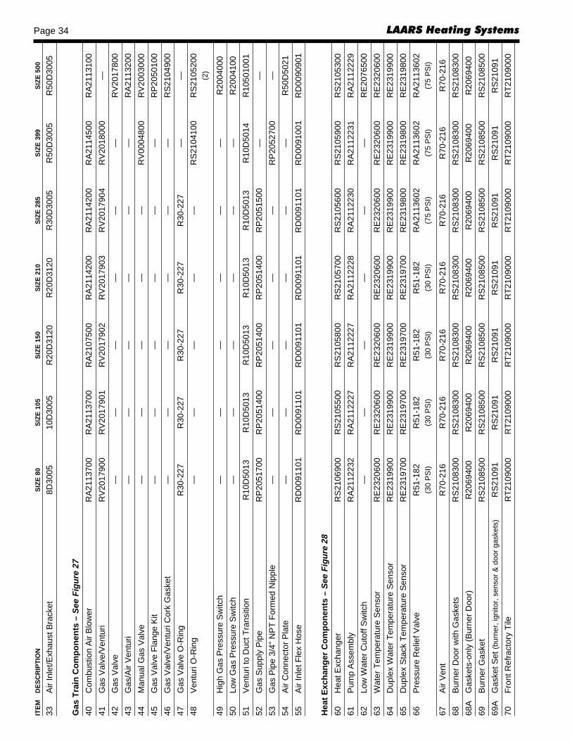
LAARS Heating SystemsPage 34IT
EMD
ESC
RIP
TIO
NSI
ZE 8
0SI
ZE 1
05SI
ZE 1
50SI
ZE 2
10SI
ZE 2
85SI
ZE 3
99SI
ZE 5
00
33A
ir In
let/E
xhau
st B
rack
et8D
3005
10D
3005
R20
D31
20R
20D
3120
R30
D30
05R
50D
3005
R50
D30
05
Gas
Tra
in C
ompo
nent
s –
See
Figu
re 2
740
Com
bust
ion
Air
Blo
wer
RA
2113
700
RA
2113
700
RA
2107
500
RA
2114
200
RA
2114
200
RA
2114
500
RA
2113
100
41G
as V
alve
/Ven
turi
RV
2017
900
RV
2017
901
RV
2017
902
RV
2017
903
RV
2017
904
RV
2018
000
—42
Gas
Val
ve—
——
——
—R
V20
1780
043
Gas
/Air
Ven
turi
——
——
——
RA
2113
200
44M
anua
l Gas
Val
ve—
——
——
RV
0004
800
RV
2003
000
45G
as V
alve
Fla
nge
Kit
——
——
——
RP
2050
100
46G
as V
alve
/Ven
turi
Cor
k G
aske
t—
——
——
—R
S21
0490
047
Gas
Val
ve O
-Rin
gR
30-2
27R
30-2
27R
30-2
27R
30-2
27R
30-2
27—
—48
Ven
turi
O-R
ing
——
——
—R
S21
0410
0R
S21
0520
0(2
)
49H
igh
Gas
Pre
ssur
e S
witc
h—
——
——
—R
2004
000
50Lo
w G
as P
ress
ure
Sw
itch
——
——
——
R20
0410
051
Ven
turi
to D
uct T
rans
ition
R10
D50
13R
10D
5013
R10
D50
13R
10D
5013
R10
D50
13R
10D
5014
R10
5010
0152
Gas
Sup
ply
Pip
eR
P20
5170
0R
P20
5140
0R
P20
5140
0R
P20
5140
0R
P20
5150
0—
—53
Gas
Pip
e 3/
4" N
PT
Form
ed N
ippl
e—
——
——
RP
2052
700
—54
Air
Con
nect
or P
late
——
——
——
R50
D50
2155
Air
Inle
t Fle
x H
ose
RD
0091
101
RD
0091
101
RD
0091
101
RD
0091
101
RD
0091
101
RD
0091
001
RD
0090
901
Hea
t Exc
hang
er C
ompo
nent
s –
See
Figu
re 2
860
Hea
t Exc
hang
erR
S21
0690
0R
S21
0550
0R
S21
0580
0R
S21
0570
0R
S21
0560
0R
S21
0590
0R
S21
0530
061
Pum
p A
ssem
bly
RA
2112
232
RA
2112
227
RA
2112
227
RA
2112
228
RA
2112
230
RA
2112
231
RA
2112
229
62Lo
w W
ater
Cut
off S
witc
h—
——
——
—R
E20
7650
063
Wat
er T
empe
ratu
re S
enso
rR
E23
2060
0R
E23
2060
0R
E23
2060
0R
E23
2060
0R
E23
2060
0R
E23
2060
0R
E23
2060
064
Dup
lex
Wat
er T
empe
ratu
re S
enso
rR
E23
1990
0R
E23
1990
0R
E23
1990
0R
E23
1990
0R
E23
1990
0R
E23
1990
0R
E23
1990
065
Dup
lex
Sta
ck T
empe
ratu
re S
enso
rR
E23
1970
0R
E23
1970
0R
E23
1970
0R
E23
1970
0R
E23
1980
0R
E23
1980
0R
E23
1980
066
Pre
ssur
e R
elie
f Val
veR
51-1
82R
51-1
82R
51-1
82R
51-1
82R
A21
1360
2R
A21
1360
2R
A21
1360
2(3
0 P
SI)
(30
PS
I)(3
0 P
SI)
(30
PS
I)(7
5 P
SI)
(75
PS
I)(7
5 P
SI)
67A
ir V
ent
R70
-216
R70
-216
R70
-216
R70
-216
R70
-216
R70
-216
R70
-216
68B
urne
r Doo
r with
Gas
kets
RS
2108
300
RS
2108
300
RS
2108
300
RS
2108
300
RS
2108
300
RS
2108
300
RS
2108
300
68A
Gas
kets
-onl
y (B
urne
r Doo
r)R
2069
400
R20
6940
0R
2069
400
R20
6940
0R
2069
400
R20
6940
0R
2069
400
69B
urne
r Gas
ket
RS
2108
500
RS
2108
500
RS
2108
500
RS
2108
500
RS
2108
500
RS
2108
500
RS
2108
500
69A
Gas
ket S
et (b
urne
r, ig
nito
r, se
nsor
& d
oor g
aske
ts)
RS2
1091
RS2
1091
RS2
1091
RS2
1091
RS2
1091
RS2
1091
RS2
1091
70Fr
ont R
efra
ctor
y Ti
leR
T210
9000
RT2
1090
00R
T210
9000
RT2
1090
00R
T210
9000
RT2
1090
00R
T210
9000

NeoTherm Boiler Page 35
71R
ear R
efra
ctor
y Ti
leR
T210
9100
RT2
1091
00R
T210
9100
RT2
1091
00R
T210
9100
RT2
1091
00R
T210
9100
72M
ain
Bur
ner w
/gas
ket
R20
6910
1R
2069
102
R20
6910
3R
2069
104
R20
6910
5R
2069
106
R20
6910
673
Flam
e S
enso
r w/g
aske
tR
2069
200
R20
6920
0R
2069
200
R20
6920
0R
W20
1210
0R
W20
1210
0R
W20
1210
074
Igni
tor w
/gas
ket
R20
6930
0R
2069
300
R20
6930
0R
2069
300
RW
2012
000
RW
2012
000
RW
2012
000
74A
Igni
tor G
aske
tR
W20
1330
0R
W20
1330
0R
W20
1330
0R
W20
1330
0R
W20
1330
0R
W20
1330
0R
W20
1330
074
BS
crew
, Ign
itor/F
lam
e S
enso
rm
4-.7
X8m
mm
4-.7
X8m
mm
4-.7
X8m
mm
4-.7
X8m
mm
4-.7
X8m
mm
4-.7
X8m
mm
4-.7
X8m
m74
CFl
ame/
Sen
sor G
aske
tR
W20
1340
0R
W20
1340
0R
W20
1340
0R
W20
1340
0R
W20
1340
0R
W20
1340
0R
W20
1340
075
Air/
Gas
Cha
nnel
RS
2108
400
RS
2108
600
RS
2108
600
RS
2108
700
RS
2108
700
RS
2108
700
RS
2108
800
75A
Scr
ew, A
ir/G
as C
hann
elR
S21
0940
0R
S21
0940
0R
S21
0940
0R
S21
0940
0R
S21
0940
0R
S21
0940
0R
S21
0940
0(5
)(5
)(5
)(5
)(5
)(5
)(5
)
76D
rain
R10
-143
R10
-143
R10
-143
R10
-143
R10
-143
R10
-143
R10
-143
77S
ight
Gla
ssR
S21
0900
0R
S21
0900
0R
S21
0900
0R
S21
0900
0R
S21
0900
0R
S21
0900
0R
S21
0900
0
Elec
tric
al C
ompo
nent
s –
See
Figu
re 2
980
Con
trol P
anel
Enc
losu
reR
50D
7001
R50
D70
01R
50D
7001
R50
D70
01R
50D
7001
R50
D70
01R
50D
7001
81Tr
ansf
orm
erR
E21
0870
0R
E21
0870
0R
E21
0870
0R
E21
0870
0R
E21
0870
0R
E21
0870
0R
E21
0870
082
Hig
h V
olta
ge S
hiel
dR
50D
7002
R50
D70
02R
50D
7002
R50
D70
02R
50D
7002
R50
D70
02R
50D
7002
83To
p P
anel
Bra
cket
R50
D70
03R
50D
7003
R50
D70
03R
50D
7003
R50
D70
03R
50D
7003
R50
D70
0384
Ele
ctro
nic
Con
trol M
odul
e, s
tand
ard
R50
D70
18R
50D
7016
R50
D70
14R
50D
7012
R50
D70
06R
50D
7010
R50
D70
06E
lect
roni
c C
ontro
l Mod
ule,
CS
D-1
——
——
——
R50
D70
08E
lect
roni
c C
ontro
l Mod
ule,
190
° H
igh
Lim
itR
50D
7019
R50
D70
17R
50D
7015
R50
D70
13R
50D
7007
R50
D70
11R
50D
7007
Ele
ctro
nic
Con
trol M
odul
e, 1
90°
Hig
h Li
mit,
CS
D-1
——
——
——
R50
D70
0985
Roc
ker S
witc
hR
E23
2270
0R
E23
2270
0R
E23
2270
0R
E23
2270
0R
E23
2270
0R
E23
2270
0R
E23
2270
086
Con
trol D
ispl
ayR
E23
2660
0R
E23
2660
0R
E23
2660
0R
E23
2660
0R
E23
2660
0R
E23
2660
0R
E23
2660
087
Wire
Har
ness
R50
D74
07R
50D
7407
R50
D74
07R
50D
7407
R50
D74
07R
50D
7405
R50
D74
0188
CS
D-1
Wire
Har
ness
——
——
——
R50
D74
03
ITEM
DES
CR
IPTI
ON
SIZE
80
SIZE
105
SIZE
150
SIZE
210
SIZE
285
SIZE
399
SIZE
500
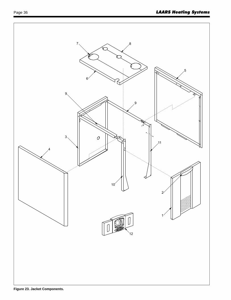
LAARS Heating SystemsPage 36
Figure 23. Jacket Components.

NeoTherm Boiler Page 37
Figure 24A. Internal Components, sizes 80–210. Figure 24B. Internal Components, sizes 285–500.

LAARS Heating SystemsPage 38
Figure 25. Gas Train Components.

NeoTherm Boiler Page 39
Figure 26. Heat Exchanger Components.

LAARS Heating SystemsPage 40
H23
3050
0A
800.900.9276 • Fax 800.559.1583 (Customer Service, Service Advisors)20 Industrial Way, Rochester, NH 03867 • 603.335.6300 • Fax 603.335.3355 (Applications Engineering)
1869 Sismet Road, Mississauga, Ontario, Canada L4W 1W8 • 905.238.0100 • Fax 905.366.0130www.Laars.com Litho in U.S.A. © Laars Heating Systems 0811 Document 1218A
®
Figure 27 Electrical Components.


![Caliper Operation Instructions[1]](https://img.pdfslide.us/doc/110x75/577cc5701a28aba7119c6424/caliper-operation-instructions1.jpg)