Embed Size (px)
Citation preview
INTEROPERABILITY NOW
Installation and Operation Guide
RSP-Z2
Dual Channel
Radio to IP Interface
Designed and Manufactured by:
JPS Interoperability Solutions
5800 Departure Drive
Raleigh, NC 27616
919-790-1011
Email: [email protected] / [email protected]
www.jpsinterop.com
JPS P/N 5160-600200 Revision 1.1 April 2018
RSP-Z2 Install & Operate
2 Interoperability Now
FEDERAL COMMUNICATIONS COMMISSION
(FCC) COMPLIANCE NOTICE:
RADIO FREQUENCY INTERFERENCE NOTICE
This equipment has been tested and found to comply with the limits for a Class A
digital device, pursuant to Part 15 of the FCC Rules. These limits are designed to
provide reasonable protection against harmful interference when the equipment is
operated in a commercial environment. This equipment generates, uses, and can
radiate radio frequency energy and, if not installed and used in accordance with the
instruction manual, may cause harmful interference to radio
communications. Operation of this equipment in a residential area is likely to cause
harmful interference in which case users will be required to correct the interference at
their own expense.
CAUTION
Changes or modifications to this equipment not expressly approved by JPS
Interoperability Solutions could void the user’s authority to operate this
equipment.
NOTICE
JPS Interoperability Solutions reserves the right to make changes to the
equipment and specifications without prior notice.
PROPRIETARY STATEMENT
The information contained in this manual is the property of JPS Interoperability
Solutions and is intended for the purchaser’s use only. It may not be reproduced
without the expressed written consent of JPS Interoperability Solutions.
© 2018 JPS Interoperability Solutions, Inc.
JPS Interoperability Solutions, Inc.
Phone: (919) 790-1011
Fax: (919) 865-1400
E-mail: [email protected] / [email protected]
5800 Departure Drive
Raleigh, NC 27616
RSP-Z2 Install & Operate
Interoperability Now 3
Table Of Contents
1 RSP-Z2 OVERVIEW...................................................................................................................... 1-1
1.1 SCOPE ............................................................................................................................................ 1-1 1.2 IMPORTANT DEFINITIONS: ........................................................................................................... 1-1 1.3 CONTEXT-SENSITIVE HELP .......................................................................................................... 1-2 1.4 POSSIBLE RSP-Z2 CONFIGURATIONS ......................................................................................... 1-3 1.4.1 INDEPENDENT PASSTHROUGH 1-3 1.4.2 CROSS-CONNECTED 1-5 1.4.3 CROSS-CONNECTED WITH BACKHAUL 1-6 1.5 FRONT PANEL LEVEL INDICATOR ............................................................................................... 1-6 1.6 USB HEADSET ............................................................................................................................... 1-7 1.7 CONFIGURATION AND CONTROL METHODOLOGY .................................................................... 1-8 1.8 SPECIFICATIONS............................................................................................................................ 1-9 1.9 EQUIPMENT AND ACCESSORIES SUPPLIED ............................................................................... 1-10 1.10 OPTIONAL EQUIPMENT: NOT SUPPLIED ................................................................................. 1-11
2 INSTALLATION ............................................................................................................................ 2-1
2.1 GENERAL ....................................................................................................................................... 2-1 2.2 UNPACKING AND INSPECTION ...................................................................................................... 2-1 2.3 RESHIPMENT OF EQUIPMENT ...................................................................................................... 2-1 2.4 INSTALLATION CONSIDERATIONS ............................................................................................... 2-2 2.5 MECHANICAL PACKAGE .............................................................................................................. 2-2 2.6 CONNECTORS, CONTROLS, AND INDICATORS ............................................................................. 2-3 2.7 RADIO INTERFACE AND CABLES .................................................................................................. 2-4 2.8 POWER SOURCE ............................................................................................................................ 2-4 2.9 SAFETY PRECAUTIONS AND PROCEDURES .................................................................................. 2-4 2.10 MAINTENANCE ............................................................................................................................ 2-4
3 WEB-BASED CONFIGURATION ............................................................................................... 3-1
3.1 SET UP IP ADDRESS AND SUBNET MASK ..................................................................................... 3-1 3.2 LOG IN ........................................................................................................................................... 3-1 3.3 NETWORK CONFIGURATION ........................................................................................................ 3-2 3.3.1 IP ADDRESS DETERMINATION AND CHANGE VIA USB PORT 3-2 3.3.2 FIRMWARE UPDATE 3-3 3.3.3 LICENSE UPDATE 3-4
4 SECURITY - USER TYPES & PERMISSIONS ......................................................................... 4-1
5 RSP-Z2 CONFIGURATION ......................................................................................................... 5-1
5.1 BASIC SYSTEM CONFIGURATION SELECTION............................................................................. 5-1 5.2 CHANNEL SELECTION AND SETTINGS CONFIGURATION ........................................................... 5-3 5.3 CHANNEL SETTINGS ..................................................................................................................... 5-4
RSP-Z2 Install & Operate
4 Interoperability Now
5.4 CHANNEL PROFILES ..................................................................................................................... 5-7 5.5 CHANNEL PROFILES BASIC INFORMATION ............................................................................... 5-10 5.6 CHANNEL SETTINGS – UNIVERSAL ............................................................................................ 5-11 5.6.1 BASIC SETTINGS 5-11 5.6.2 AUDIO PRIORITY 5-12 5.7 LOCAL CHANNEL SETTINGS – USB HEADSET .......................................................................... 5-13 5.8 LOCAL CHANNEL SETTINGS – RADIO ....................................................................................... 5-14 5.9 BACKHAUL CHANNEL SETTINGS – ROIP, SIP, RTP, JPS VIA ................................................ 5-17 5.10 RETURNING CONFIGURATION AND CHANNEL SETTINGS BACK TO FACTORY DEFAULTS .. 5-18
6 FIELD SETUP & OPTIMIZATION............................................................................................. 6-1
6.1 RADIO INTERFACE USING JPS CUSTOM RADIO CABLES ........................................................... 6-2 6.1.1 RX AUDIO LEVEL (RECEIVE INPUT): 6-2 6.2 TX AUDIO LEVEL (TRANSMIT GAIN): ......................................................................................... 6-2 6.2.1 VOX OR VMR THRESHOLD: 6-3 6.2.2 TRANSMIT AUDIO DELAY 6-3 6.3 RX AUDIO DELAY ......................................................................................................................... 6-4 6.3.1 AUDIO LEVELS AND DELAYS FOR TRANSPORT CHANNELS 6-4 6.4 RADIO INTERFACE USING CUSTOMER-DESIGNED RADIO CABLES ........................................... 6-4 6.5 RADIO INTERFACE TROUBLESHOOTING TIPS ............................................................................ 6-5 6.5.1 SYMPTOM: USER IN FIELD COMPLAINS OF MISSED FIRST SYLLABLES 6-5 6.5.2 SYMPTOM: USER IN FIELD COMPLAINS OF MISSED SYLLABLES MID-CONVERSATION 6-5 6.5.3 SYMPTOM: CONTINUOUS PING-PONG OF COR / PTT BETWEEN CROSS CONNECTED RADIOS 6-5 6.5.4 SYMPTOM: FALSE KEYING OF DONOR RADIO BY RADIO CHANNEL 6-5 6.5.5 SYMPTOM: RADIO CHANNEL EXPERIENCING CONTINUOUS ACTIVE COR STATE 6-5 6.5.6 SYMPTOM: AUDIO SOUNDS TOO WEAK 6-6 6.5.7 SYMPTOM: AUDIO SOUNDS TOO LOUD OR DISTORTED 6-6
7 OPERATING INSTRUCTIONS ................................................................................................... 7-1
7.1 USB HEADSET OPERATION .......................................................................................................... 7-1 7.1.1 USB HEADSET OPERATION, PTT MODE 7-4 7.2 DIAL OUT OPERATION ................................................................................................................. 7-5 7.3 LIVE STATUS INFORMATION ........................................................................................................ 7-6
8 RECENT UPGRADES TO THE RSP-Z2 .................................................................................... 8-1
8.1 NEW/UPDATED FEATURES ........................................................................................................... 8-1
RSP-Z2 Install & Operate
Interoperability Now 5
Glossary
ACUs JPS Interoperability devices of various form factors that interface different types of
communications devices. Include ACU-1000/2000/M/T/5000/Z1.
ARA-1 JPS device that provides a SIP interface to an individual radio or other four-wire device.
BSI Bridging Systems Interface – A specification jointly developed by government and industry to
provide a standard interface for radio interoperability systems. The BSI is based on SIP and RTP
and allows bridging of radio nets between disparate interoperability systems.
COR Carrier Operated Relay - A receiver signal that gives a positive indication a carrier or signal is
being received and the receiver is unsquelched. Same as COS.
COS Carrier Operated Squelch - See COR.
Cross-
Connection
A link made between two communications systems interfaced to a single ACU-5000 chassis, or
between systems interfaced over a network to two or more ACU-5000 systems.
DTMF Dual Tone Multi Frequency - The standard touch-tone telephone dialing method sends DTMF
audio characters over a PSTN line for control purposes. Can also be used with FM radio.
DSP Digital Signal Processing (or Processor).
Hangtime A system with hangtime will remain in the transmit mode for the duration of the set hangtime
beyond the time indicated by any keying inputs. The hangtime prevents transmitter unkey during
brief pauses in the transmission.
Key To key a transmitter means to cause it to transmit.
LMR Land Mobile Radio.
Mute To quiet or inhibit audio.
NXU-2A Network Extension Unit. A JPS device that interfaces a radio or other 4-wire device to other
communications devices over an IP network. An NXU-2A uses RoIP.
PBX Private Branch Exchange. A telephone system that owned an operated by a private company (such
as a manufacturing business) rather than by a telephone company such as ATT.
PCB Printed Circuit Board.
PSTN Public Switched Telephone Network - The world's public circuit-switched telephone network
which provides connectivity to fixed-line and mobile telephones.
PTT Push-to-Talk. An active PTT signal causes a transmitter to key.
RJ-11 Registered Jack 11 - A physical interface for connecting wires, often used to terminate telephone
cables. It is a 6-position 4-contact (6P4C) connector. Although it can be used for other purposes,
this is commonly referred to as a standard phone jack or connector.
RoIP Radio over Internet Protocol. JPS proprietary protocol which sends voice plus radio control signals
over an IP network.
RX Receiver or Receiving.
SIP Session Initiation Protocol – A flexible, standards-based, open protocol that initiates and manages
communications between devices over an IP network.
Soft Phone A computer that’s used as a VoIP phone.
Squelch A means of detecting audio and causing some action when it is present, such as keying a transmitter
or unmuting an audio path.
TX Transmit or Transmitter.
VMR Voice Modulation Recognition. An algorithm which causes a transmitter to key or causes some
other action when voice is present. This squelch type is activated by only by human voice, and not
by tones, noise or other non-speech audio. Particularly useful for noisy signals such as HF.
VoIP Voice Over Internet Protocol - Protocol for delivering voice communications over IP networks.
Most network-phone providers (such as Vonage), use VoIP.
VOX Voice Operated Xmit (Transmit). A circuit or algorithm which causes a transmitter to key or causes
some other action when sound is present. This squelch type is activated by any audio signal, and
is not restricted to voice only.

RSP-Z2 Install & Operate
6 Interoperability Now
blank page
RSP-Z2 Install & Operate
Interoperability Now 1-1
1 RSP-Z2 Overview
1.1 Scope
This document provides a description, specifications, and configuration and operating
instructions for the Dual-Radio version of the RSP-Z2.
This section provides some essential background information that will assist in understanding
the capabilities of the RSP-Z2.
JPS Interoperability Solutions has several decades of experience with voice communications
interoperability, fielding their first devices in 1989. Over this time the company has encountered
and resolved a wide array of problems that can hamper or complicate communications when
disparate devices are patched together into interoperability nets.
The RSP-Z2 incorporates all this experience, in the form of a suite of sophisticated DSP
algorithms that operate at its interfaces with any connected communications devices, as well as
many custom radio interface cables, covering well over 300 different radio makes and models.
JPS interoperability devices are also known for simplicity and ease-of-use. The RSP-Z2’s
browser-based Graphical User Interface is carefully designed to make these sophisticated
capabilities available when necessary. When the simple setup and configuration works well, an
installer and operator need only be concerned with these elements. However, if the
communications system includes any problematic elements, a JPS interoperability device (such
as this RSP-Z2) has the features necessary to resolve the problems and optimize communications.
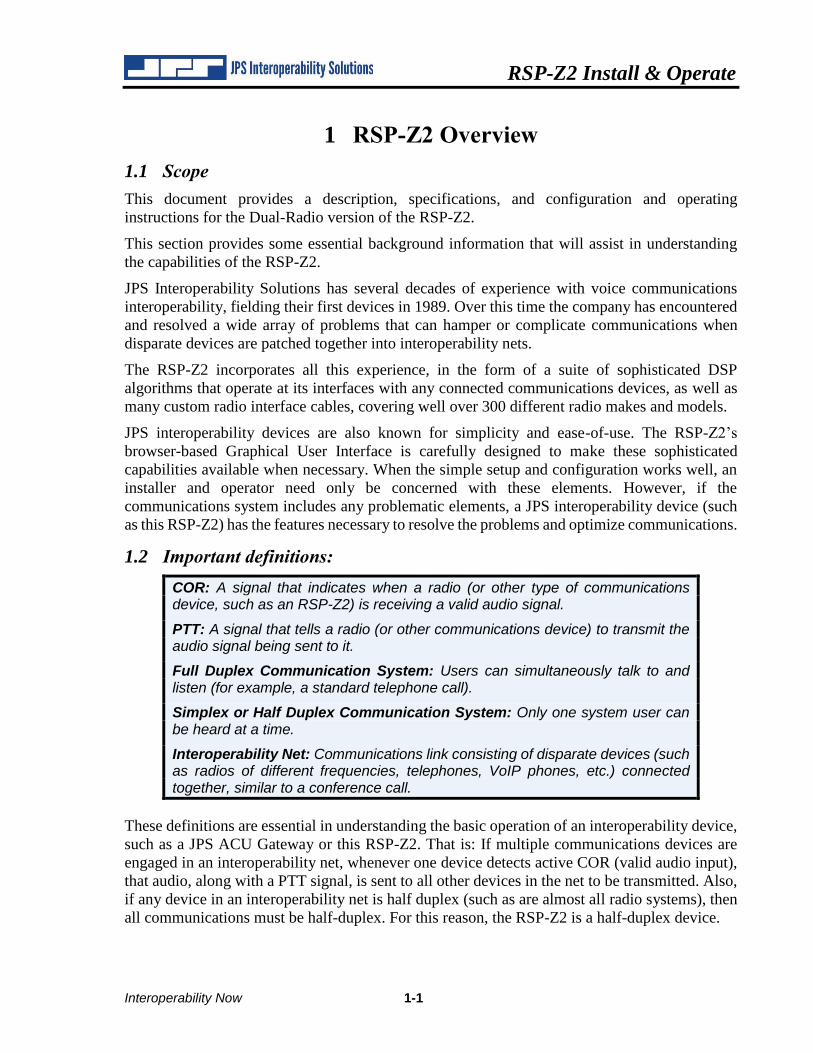
1.2 Important definitions:
COR: A signal that indicates when a radio (or other type of communications device, such as an RSP-Z2) is receiving a valid audio signal.
PTT: A signal that tells a radio (or other communications device) to transmit the audio signal being sent to it.
Full Duplex Communication System: Users can simultaneously talk to and listen (for example, a standard telephone call).
Simplex or Half Duplex Communication System: Only one system user can be heard at a time.
Interoperability Net: Communications link consisting of disparate devices (such as radios of different frequencies, telephones, VoIP phones, etc.) connected together, similar to a conference call.
These definitions are essential in understanding the basic operation of an interoperability device,
such as a JPS ACU Gateway or this RSP-Z2. That is: If multiple communications devices are
engaged in an interoperability net, whenever one device detects active COR (valid audio input),
that audio, along with a PTT signal, is sent to all other devices in the net to be transmitted. Also,
if any device in an interoperability net is half duplex (such as are almost all radio systems), then
all communications must be half-duplex. For this reason, the RSP-Z2 is a half-duplex device.
RSP-Z2 Install & Operate
1-2 Interoperability Now
Among the unit’s sophisticated features are various methods for determining active COR (as
VOX or VMR are optimal or necessary for some types of devices), and adjustable audio delays
to meet the timing requirements of the connected communications systems.
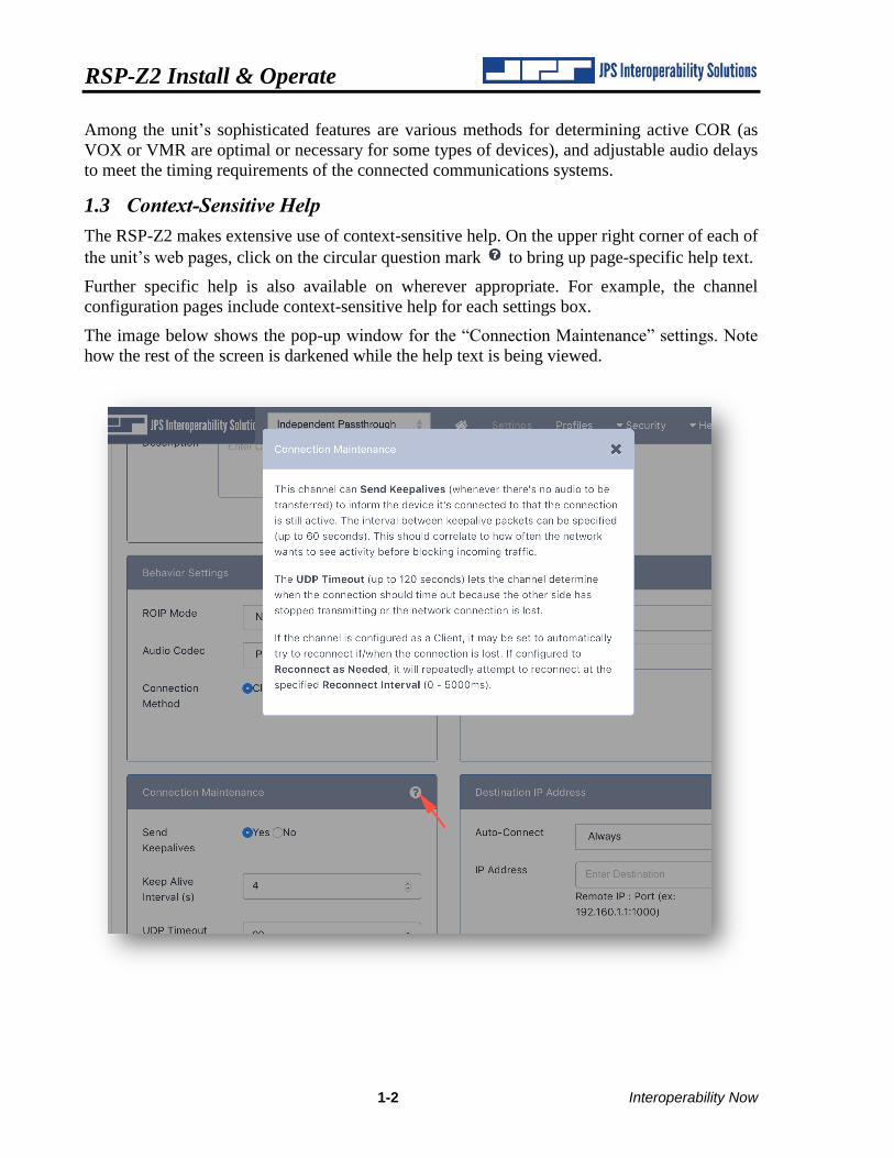
1.3 Context-Sensitive Help
The RSP-Z2 makes extensive use of context-sensitive help. On the upper right corner of each of
the unit’s web pages, click on the circular question mark to bring up page-specific help text.
Further specific help is also available on wherever appropriate. For example, the channel
configuration pages include context-sensitive help for each settings box.
The image below shows the pop-up window for the “Connection Maintenance” settings. Note
how the rest of the screen is darkened while the help text is being viewed.
RSP-Z2 Install & Operate
Interoperability Now 1-3
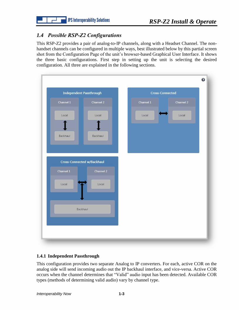
1.4 Possible RSP-Z2 Configurations
This RSP-Z2 provides a pair of analog-to-IP channels, along with a Headset Channel. The non-
handset channels can be configured in multiple ways, best illustrated below by this partial screen
shot from the Configuration Page of the unit’s browser-based Graphical User Interface. It shows
the three basic configurations. First step in setting up the unit is selecting the desired
configuration. All three are explained in the following sections.
1.4.1 Independent Passthrough
This configuration provides two separate Analog to IP converters. For each, active COR on the
analog side will send incoming audio out the IP backhaul interface, and vice-versa. Active COR
occurs when the channel determines that “Valid” audio input has been detected. Available COR
types (methods of determining valid audio) vary by channel type.
RSP-Z2 Install & Operate
1-4 Interoperability Now
Note that four separate channels are depicted for this configuration – two local audio channels
each tied to its own IP backhaul channel. A USB Headset can also be included, and connected to
any communications channel.
Once a configuration is selected, right-clicking on any channel icon will bring up the Settings
Page for that channel; this allows the channel to be set to a variety of Channel Types, with
appropriate settings options for the selected type.
For this RSP-Z2, the analog options are Radio (appropriate also for other types of four-wire
devices), and Headset (which allows the unit to me used as a small IP dispatch station). Future
versions will include a PSTN analog channel.
Backhaul options include RTP, SIP (BSI compliant), RoIP (the JPS-proprietary Radio over IP
protocol), VIA (for connection to the JPS VIA Smartphone PoC app), and Bridge Channels (for
future applications when used in a system with other JPS devices).
Note that, if desired, the analog channels can also be configured as either of the RoIP, RTP, or
SIP channel types.
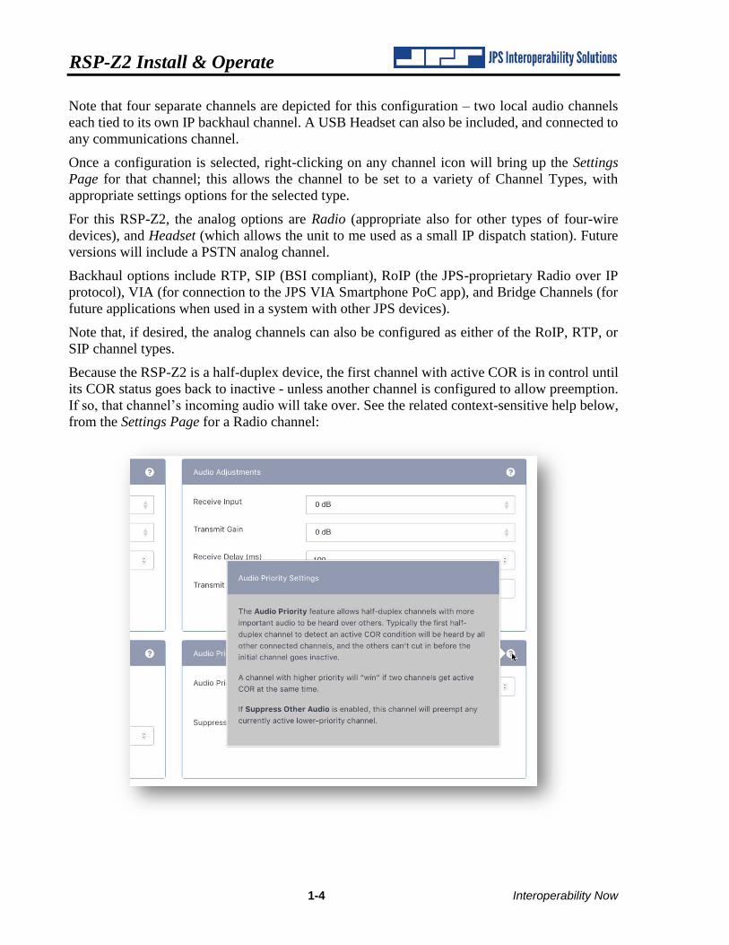
Because the RSP-Z2 is a half-duplex device, the first channel with active COR is in control until
its COR status goes back to inactive - unless another channel is configured to allow preemption.
If so, that channel’s incoming audio will take over. See the related context-sensitive help below,
from the Settings Page for a Radio channel:
RSP-Z2 Install & Operate
Interoperability Now 1-5
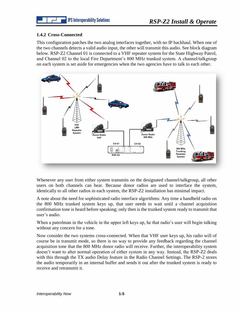
1.4.2 Cross-Connected
This configuration patches the two analog interfaces together, with no IP backhaul. When one of
the two channels detects a valid audio input, the other will transmit this audio. See block diagram
below. RSP-Z2 Channel 01 is connected to a VHF repeater system for the State Highway Patrol,
and Channel 02 to the local Fire Department’s 800 MHz trunked system. A channel/talkgroup
on each system is set aside for emergencies when the two agencies have to talk to each other.
Whenever any user from either system transmits on the designated channel/talkgroup, all other
users on both channels can hear. Because donor radios are used to interface the system,
identically to all other radios in each system, the RSP-Z2 installation has minimal impact.
A note about the need for sophisticated radio interface algorithms: Any time a handheld radio on
the 800 MHz trunked system keys up, that user needs to wait until a channel acquisition
confirmation tone is heard before speaking; only then is the trunked system ready to transmit that
user’s audio.
When a patrolman in the vehicle in the upper left keys up, he that radio’s user will begin talking
without any concern for a tone.
Now consider the two systems cross-connected. When that VHF user keys up, his radio will of
course be in transmit mode, so there is no way to provide any feedback regarding the channel
acquisition tone that the 800 MHz donor radio will receive. Further, the interoperability system
doesn’t want to alter normal operation of either system in any way. Instead, the RSP-Z2 deals
with this through the TX audio Delay feature in the Radio Channel Settings. The RSP-2 stores
the audio temporarily in an internal buffer and sends it out after the trunked system is ready to
receive and retransmit it.
RSP-Z2 Install & Operate
1-6 Interoperability Now
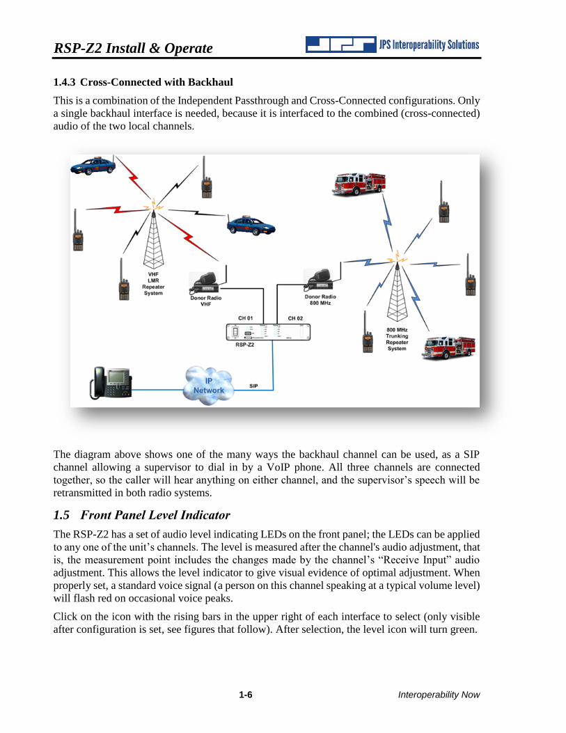
1.4.3 Cross-Connected with Backhaul
This is a combination of the Independent Passthrough and Cross-Connected configurations. Only
a single backhaul interface is needed, because it is interfaced to the combined (cross-connected)
audio of the two local channels.
The diagram above shows one of the many ways the backhaul channel can be used, as a SIP
channel allowing a supervisor to dial in by a VoIP phone. All three channels are connected
together, so the caller will hear anything on either channel, and the supervisor’s speech will be
retransmitted in both radio systems.
1.5 Front Panel Level Indicator
The RSP-Z2 has a set of audio level indicating LEDs on the front panel; the LEDs can be applied
to any one of the unit’s channels. The level is measured after the channel's audio adjustment, that
is, the measurement point includes the changes made by the channel’s “Receive Input” audio
adjustment. This allows the level indicator to give visual evidence of optimal adjustment. When
properly set, a standard voice signal (a person on this channel speaking at a typical volume level)
will flash red on occasional voice peaks.
Click on the icon with the rising bars in the upper right of each interface to select (only visible
after configuration is set, see figures that follow). After selection, the level icon will turn green.
RSP-Z2 Install & Operate
Interoperability Now 1-7
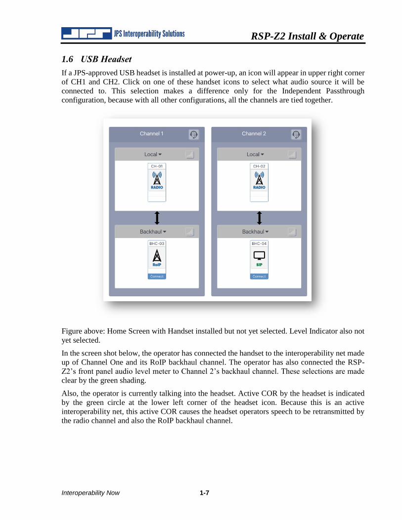
1.6 USB Headset
If a JPS-approved USB headset is installed at power-up, an icon will appear in upper right corner
of CH1 and CH2. Click on one of these handset icons to select what audio source it will be
connected to. This selection makes a difference only for the Independent Passthrough
configuration, because with all other configurations, all the channels are tied together.
Figure above: Home Screen with Handset installed but not yet selected. Level Indicator also not
yet selected.
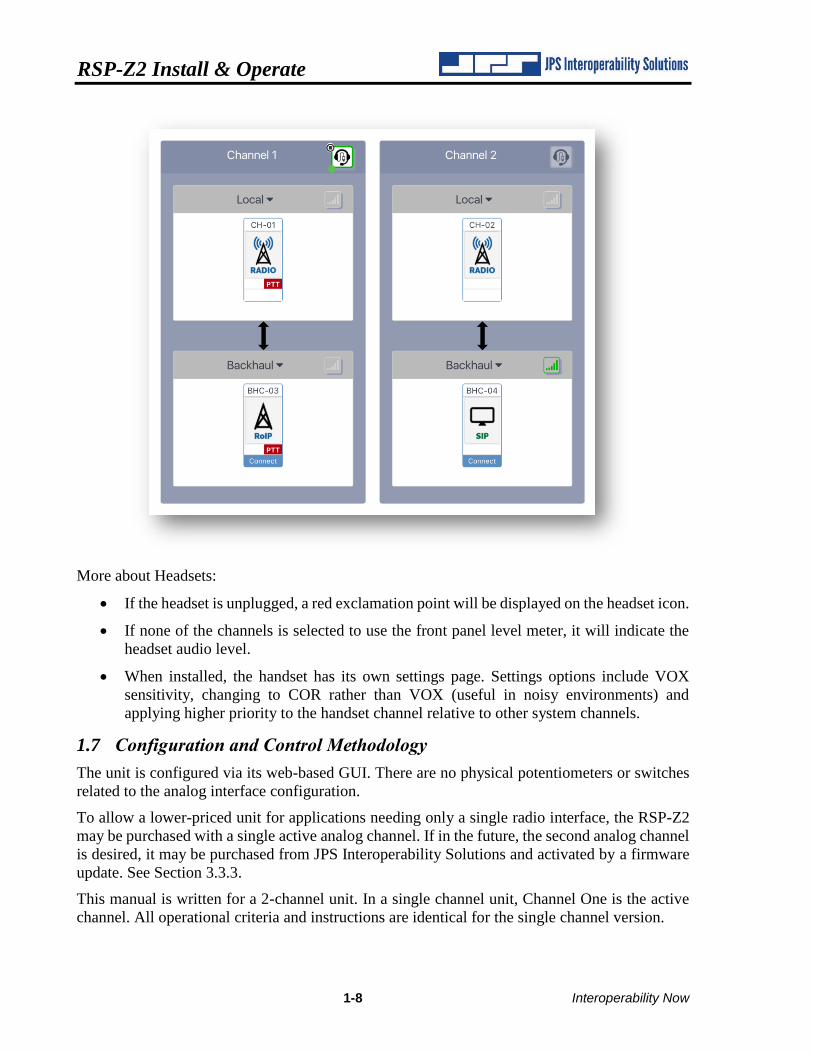
In the screen shot below, the operator has connected the handset to the interoperability net made
up of Channel One and its RoIP backhaul channel. The operator has also connected the RSP-
Z2’s front panel audio level meter to Channel 2’s backhaul channel. These selections are made
clear by the green shading.
Also, the operator is currently talking into the headset. Active COR by the headset is indicated
by the green circle at the lower left corner of the headset icon. Because this is an active
interoperability net, this active COR causes the headset operators speech to be retransmitted by
the radio channel and also the RoIP backhaul channel.
RSP-Z2 Install & Operate
1-8 Interoperability Now
More about Headsets:
• If the headset is unplugged, a red exclamation point will be displayed on the headset icon.
• If none of the channels is selected to use the front panel level meter, it will indicate the
headset audio level.
• When installed, the handset has its own settings page. Settings options include VOX
sensitivity, changing to COR rather than VOX (useful in noisy environments) and
applying higher priority to the handset channel relative to other system channels.
1.7 Configuration and Control Methodology
The unit is configured via its web-based GUI. There are no physical potentiometers or switches
related to the analog interface configuration.
To allow a lower-priced unit for applications needing only a single radio interface, the RSP-Z2
may be purchased with a single active analog channel. If in the future, the second analog channel
is desired, it may be purchased from JPS Interoperability Solutions and activated by a firmware
update. See Section 3.3.3.
This manual is written for a 2-channel unit. In a single channel unit, Channel One is the active
channel. All operational criteria and instructions are identical for the single channel version.
RSP-Z2 Install & Operate
Interoperability Now 1-9
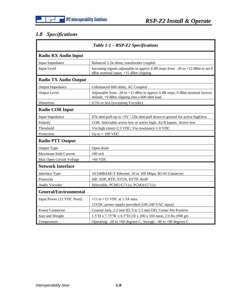
1.8 Specifications
Table 1-1 – RSP-Z2 Specifications
Radio RX Audio Input
Input Impedance Balanced 2.2k ohms, transformer coupled
Input Level Incoming signals adjustable in approx 4 dB steps from –26 to +12 dBm to set 0
dBm nominal input; +15 dBm clipping
Radio TX Audio Output
Output Impedance Unbalanced 600 ohms, AC Coupled
Output Level Adjustable from –26 to +12 dBm in approx 4 dB steps, 0 dBm nominal factory
default; +9 dBm clipping into a 600 ohm load
Distortion 0.5% or less (excepting Vocoder)
Radio COR Input
Input Impedance 47k ohm pull-up to +5V / 22k ohm pull down to ground for active high/low
Polarity COR: Selectable active low or active high; AUX Inputs: Active low
Threshold Vin high (min)=2.3 VDC; Vin low(max)=1.0 VDC
Protection Up to + 100 VDC
Radio PTT Output
Output Type Open drain
Maximum Sink Current 100 mA
Max Open Circuit Voltage +60 VDC
Network Interface
Interface Type 10/100BASE-T Ethernet, 10 or 100 Mbps; RJ-45 Connector
Protocols SIP, SDP, RTP, STUN, HTTP, RoIP
Audio Vocoder Selectable, PCMU/G711u, PCMA/G711a
General/Environmental
Input Power (12 VDC Nom) +11 to +15 VDC at 1.5A max.
12VDC power supply provided (100-240 VAC input)
Power Connector Coaxial Jack, 2.5 mm ID, 5 to 5.5 mm OD; Center Pin Positive
Size and Weight 1.5”H x 7.75”W x 6.5”D (38 x 200 x 160 mm); 2.0 lbs (900 gr)
Temperature Operating: -20 to +60 degrees C; Storage: -40 to +80 degrees C
RSP-Z2 Install & Operate
1-10 Interoperability Now
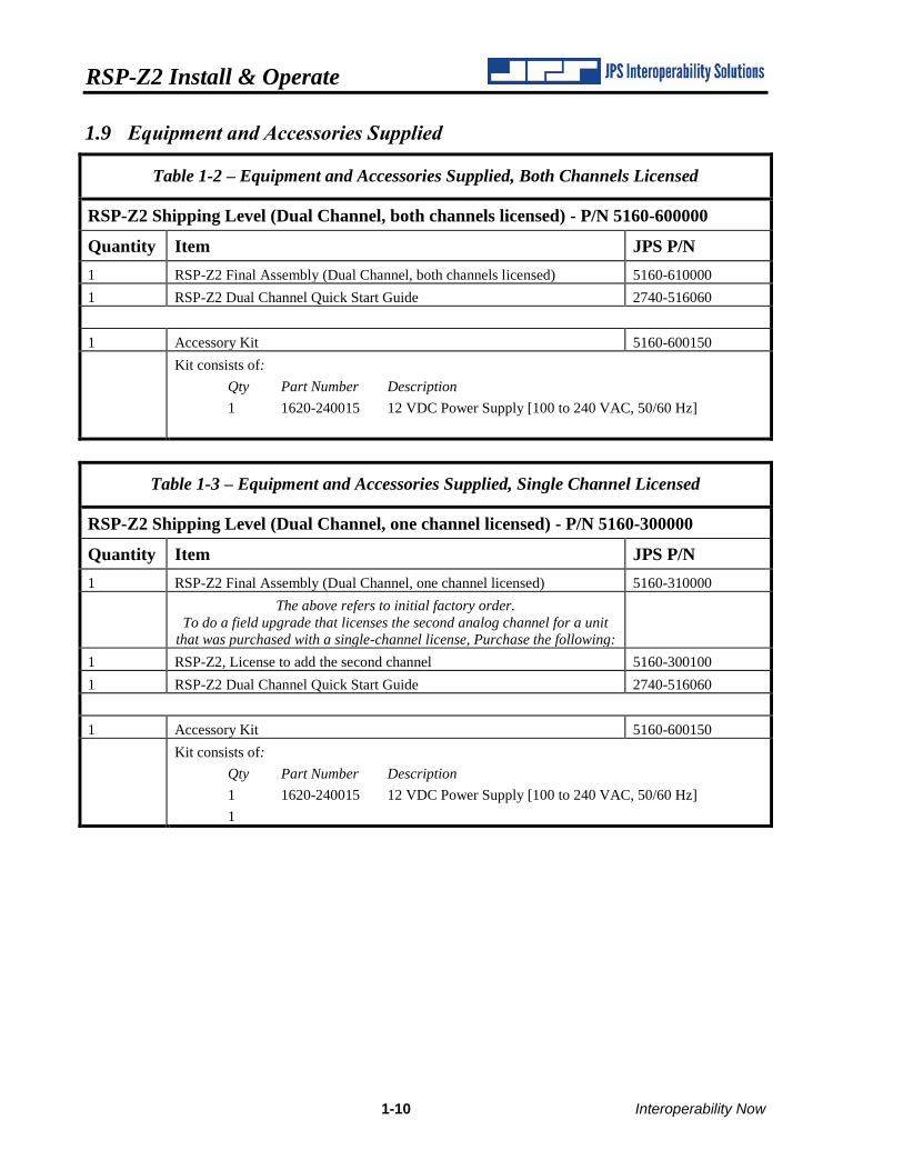
1.9 Equipment and Accessories Supplied
Table 1-2 – Equipment and Accessories Supplied, Both Channels Licensed
RSP-Z2 Shipping Level (Dual Channel, both channels licensed) - P/N 5160-600000
Quantity Item JPS P/N
1 RSP-Z2 Final Assembly (Dual Channel, both channels licensed) 5160-610000
1 RSP-Z2 Dual Channel Quick Start Guide 2740-516060
1 Accessory Kit 5160-600150
Kit consists of:
Qty Part Number Description
1 1620-240015 12 VDC Power Supply [100 to 240 VAC, 50/60 Hz]
Table 1-3 – Equipment and Accessories Supplied, Single Channel Licensed
RSP-Z2 Shipping Level (Dual Channel, one channel licensed) - P/N 5160-300000
Quantity Item JPS P/N
1 RSP-Z2 Final Assembly (Dual Channel, one channel licensed) 5160-310000
The above refers to initial factory order.
To do a field upgrade that licenses the second analog channel for a unit
that was purchased with a single-channel license, Purchase the following:
1 RSP-Z2, License to add the second channel 5160-300100
1 RSP-Z2 Dual Channel Quick Start Guide 2740-516060
1 Accessory Kit 5160-600150
Kit consists of:
Qty Part Number Description
1 1620-240015 12 VDC Power Supply [100 to 240 VAC, 50/60 Hz]
1
RSP-Z2 Install & Operate
Interoperability Now 1-11
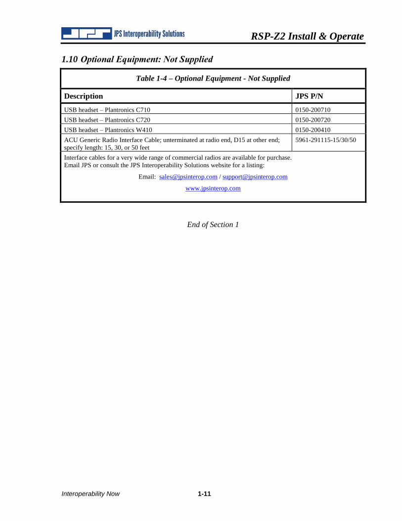
1.10 Optional Equipment: Not Supplied
Table 1-4 – Optional Equipment - Not Supplied
Description JPS P/N
USB headset – Plantronics C710 0150-200710
USB headset – Plantronics C720 0150-200720
USB headset – Plantronics W410 0150-200410
ACU Generic Radio Interface Cable; unterminated at radio end, D15 at other end;
specify length: 15, 30, or 50 feet
5961-291115-15/30/50
Interface cables for a very wide range of commercial radios are available for purchase.
Email JPS or consult the JPS Interoperability Solutions website for a listing:
Email: [email protected] / [email protected]
www.jpsinterop.com
End of Section 1

RSP-Z2 Install & Operate
Interoperability Now 2-1
2 Installation
2.1 General
This section provides the instructions for unpacking, inspection, and installation. Configuration
and operation are explained in subsequent sections.
2.2 Unpacking and Inspection
After unpacking the unit, retain the carton and packing materials until the contents have been
inspected and checked against the packing list. If there is a shortage or any evidence of damage,
do not attempt to use the equipment. Contact the carrier and file a shipment damage claim. A
full report of the damage should be reported to the JPS Customer Service Department. The
following information should be included in the report:
1. Order Number
2. Equipment Model and Serial Numbers
3. Shipping Agency
4. Date(s) of Shipment
The JPS Interoperability Solutions Customer Service Department can be reached by phone at
(919) 790-1011, or by FAX at (919) 865-1400, or email at [email protected]. Upon receipt
of this information, JPS will arrange for repair or replacement of the equipment.
2.3 Reshipment of Equipment
If the RSP-Z2 must be returned, an RMA (Returned Material Authorization) number must first
be obtained from JPS. This number must be noted on the outside of the packing carton and on
all accompanying documents. When packing the unit for reshipment, it is best to use the original
packaging for the unit; if this is not possible, make sure that adequate packing material is used to
prevent excessive shocks during transport and handling.
Shipment should be made prepaid consigned to:
JPS Interoperability Solutions
Customer Service Department
5800 Departure Drive
Raleigh, North Carolina 27616
USA
Plainly, mark with indelible ink all mailing documents as follows:
GOODS RETURNED FOR REPAIR
Mark all sides of the package:
FRAGILE - ELECTRONIC EQUIPMENT
Inspect the package prior to shipment to be sure it is properly marked and securely wrapped.
RSP-Z2 Install & Operate
2-2 Interoperability Now
2.4 Installation Considerations
The RSP-Z2 must be installed in a location that provides both protection from the weather and
assurance of ambient temperatures between -20 and +60 degrees C. The unit is neither splash
proof nor corrosion resistant and must be protected from exposure to salt spray.
The unit does not have nor need an internal cooling fan.
Note: When the RSP-Z2 is installed in a high RF environment such as repeater site, it is recommended that cable assemblies to each channel be individually shielded.
Interface cables purchased from JPS are shielded.
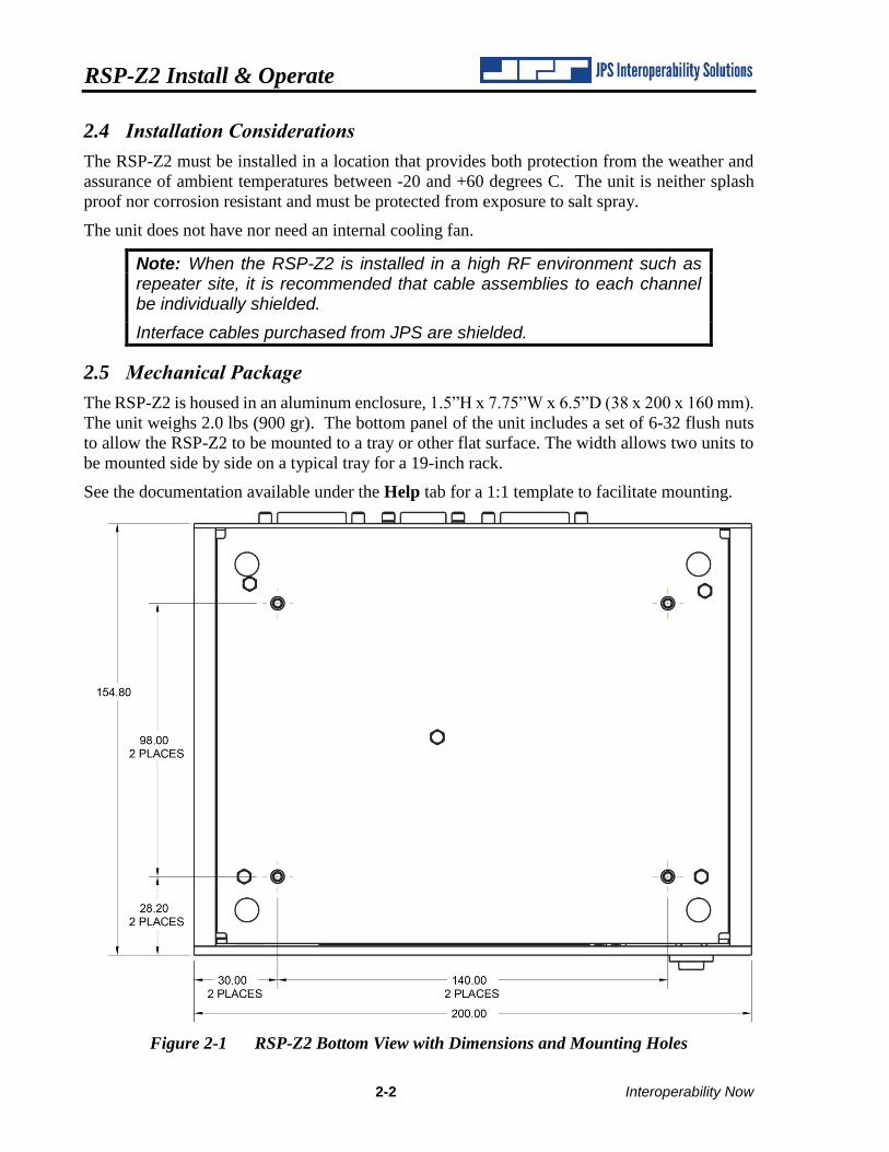
2.5 Mechanical Package
The RSP-Z2 is housed in an aluminum enclosure, 1.5”H x 7.75”W x 6.5”D (38 x 200 x 160 mm).
The unit weighs 2.0 lbs (900 gr). The bottom panel of the unit includes a set of 6-32 flush nuts
to allow the RSP-Z2 to be mounted to a tray or other flat surface. The width allows two units to
be mounted side by side on a typical tray for a 19-inch rack.
See the documentation available under the Help tab for a 1:1 template to facilitate mounting.
Figure 2-1 RSP-Z2 Bottom View with Dimensions and Mounting Holes
RSP-Z2 Install & Operate
Interoperability Now 2-3
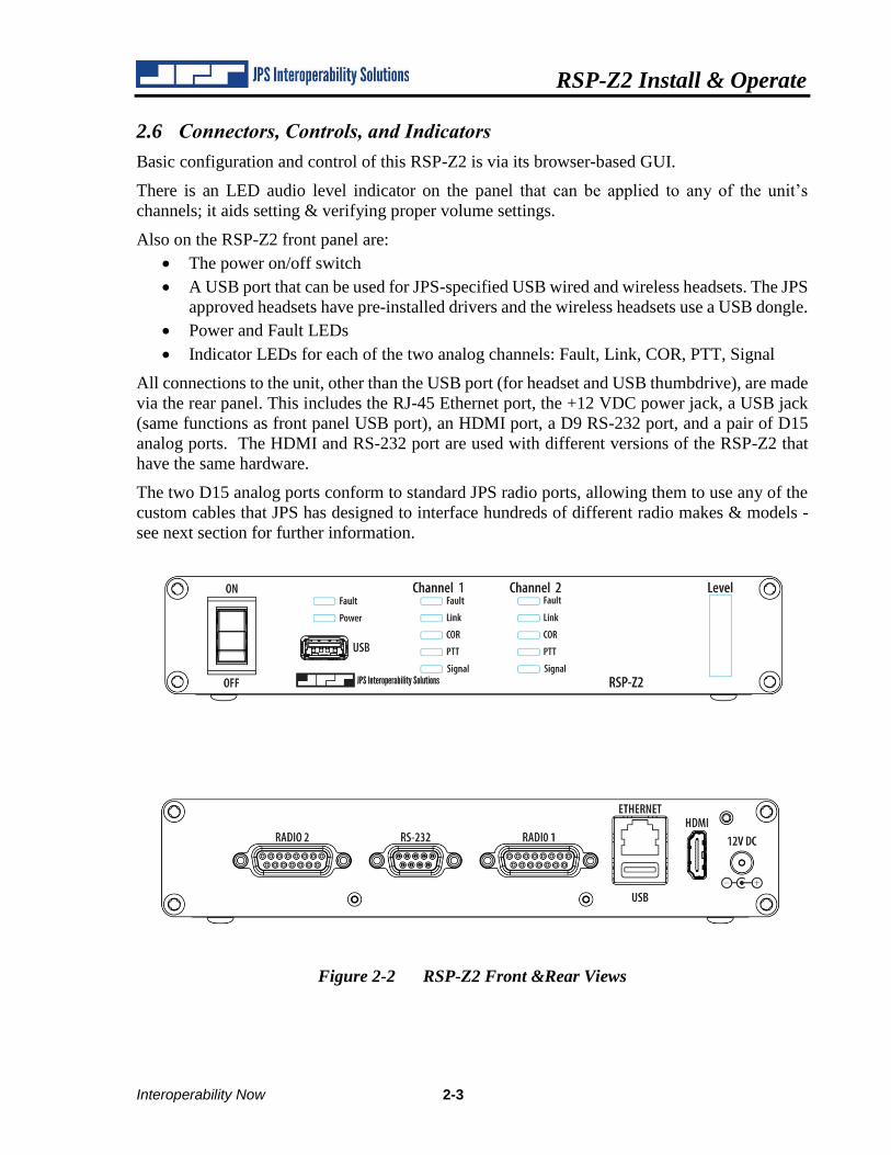
2.6 Connectors, Controls, and Indicators
Basic configuration and control of this RSP-Z2 is via its browser-based GUI.
There is an LED audio level indicator on the panel that can be applied to any of the unit’s
channels; it aids setting & verifying proper volume settings.
Also on the RSP-Z2 front panel are:
• The power on/off switch
• A USB port that can be used for JPS-specified USB wired and wireless headsets. The JPS
approved headsets have pre-installed drivers and the wireless headsets use a USB dongle.
• Power and Fault LEDs
• Indicator LEDs for each of the two analog channels: Fault, Link, COR, PTT, Signal
All connections to the unit, other than the USB port (for headset and USB thumbdrive), are made
via the rear panel. This includes the RJ-45 Ethernet port, the +12 VDC power jack, a USB jack
(same functions as front panel USB port), an HDMI port, a D9 RS-232 port, and a pair of D15
analog ports. The HDMI and RS-232 port are used with different versions of the RSP-Z2 that
have the same hardware.
The two D15 analog ports conform to standard JPS radio ports, allowing them to use any of the
custom cables that JPS has designed to interface hundreds of different radio makes & models -
see next section for further information.
Figure 2-2 RSP-Z2 Front &Rear Views
RSP-Z2 Install & Operate
2-4 Interoperability Now
2.7 Radio Interface and Cables
The physical interfaces for the radio ports (and other four-wire devices) are a pair of rear panel
D-15 connectors. Radios are connected to the RSP-Z2 via a cable that is likely to include
interfacing circuitry (such as is used with JPS-manufactured radio cables).
The RSP-Z2 is designed to allow the use of the very large library of JPS radio cables created for
the ACU Gateway product line, including standard Military 5 and 6 pin microphone connectors.
These cables allow connection to hundreds of commonly-deployed radios. See Table 1-4 –
Optional Equipment - Not Supplied.
Other cables can be designed and built on request. An unterminated cable can also be purchased;
this cable has bare wires on the radio end to allow a customer to create a cable. The JPS Customer
Service Department can be reached by phone at (919) 790-1011, or by FAX at (919) 865-1400.
A representative will explain what is required. Typically, JPS Systems Engineering will need a
pair of operational radios and radio programming software to use while creating and testing a
new cable.
2.8 Power Source
The power supply included with the unit operates from input voltages and frequencies of 100 to
240 VAC, 50 - 60 Hz. Other standard “laptop-type” supplies can be substituted, but must provide
a nominal +12 VDC, and be capable of at least 1.5 amp output. Note that the power supply
included in the RSP-Z2 accessory kit is a premium version with a 1500V isolation transformer.
2.9 Safety Precautions and Procedures
The RSP-Z2 is operated by a +12 VDC power supply and therefore any high-level power supply
voltage exists only on the AC input side of the power supply. Standard precautions relative to
115 or 230 (nominal) AC wiring applies.
Note: The RSP-Z2 contains no user-serviceable components and there is no reason to disassemble the unit. Return the RSP-Z2 to the factory for servicing.
2.10 Maintenance
The RSP-Z2 contains no user-serviceable internal components, and no maintenance is required.
End of Section 2
RSP-Z2 Install & Operate
Interoperability Now 3-1
3 Web-Based Configuration
The unit is configured via its web-based Graphical User Interface (GUI). The GUI provides a
range of easily accessible context-sensitive help information. Note: Due to ongoing upgrades and
enhancements to the RSP-Z2, the unit’s web pages may not be identical to those shown in this
guide.
The RSP-Z2 is standards-compliant and therefore supports standards-compliant web browsers,
including the recent and latest versions of Internet Explorer, Firefox, Chrome, Safari, and Opera.
If Internet Explorer is used, only IE 10 (or higher) and Edge have the capability to access all
RSP-Z2 features, so do not attempt to use earlier versions.
3.1 Set up IP Address and Subnet Mask
As with any device with a static IP address, it will be necessary to set up the RSP-Z2 to operate
on the LAN where it is to be deployed. First step is to log in using the unit’s factory default IP
address of 192.168.1.200, with a default subnet mask of 255.255.255.0.
Connect the RSP-Z2 via CAT-5 cable directly to the Ethernet Port of the computer that will be
used to access and configure it. Set the computer to a static IP address of 192.168.1.xxx (where
xxx is a number between 2 and 199) and a subnet mask of 255.255.255.0.
Plug in the unit’s power supply, and turn the unit on via its front panel power switch. The RSP-
Z2’s front panel LEDs will flash while the unit boots up (approximately 90 seconds). Then log
in to the default. Follow through to Section 3.3 which will give instructions for changing the
network configuration parameters.
3.2 Log In
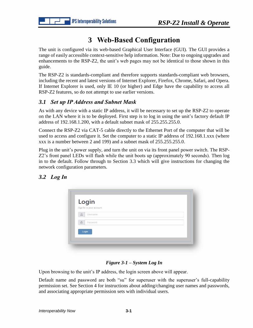
Figure 3-1 – System Log In
Upon browsing to the unit’s IP address, the login screen above will appear.
Default name and password are both “su” for superuser with the superuser’s full-capability
permission set. See Section 4 for instructions about adding/changing user names and passwords,
and associating appropriate permission sets with individual users.
RSP-Z2 Install & Operate
3-2 Interoperability Now
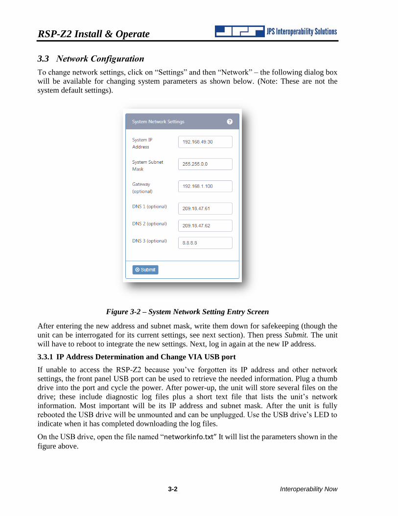
3.3 Network Configuration
To change network settings, click on “Settings” and then “Network” – the following dialog box
will be available for changing system parameters as shown below. (Note: These are not the
system default settings).
Figure 3-2 – System Network Setting Entry Screen
After entering the new address and subnet mask, write them down for safekeeping (though the
unit can be interrogated for its current settings, see next section). Then press Submit. The unit
will have to reboot to integrate the new settings. Next, log in again at the new IP address.
3.3.1 IP Address Determination and Change VIA USB port
If unable to access the RSP-Z2 because you’ve forgotten its IP address and other network
settings, the front panel USB port can be used to retrieve the needed information. Plug a thumb
drive into the port and cycle the power. After power-up, the unit will store several files on the
drive; these include diagnostic log files plus a short text file that lists the unit’s network
information. Most important will be its IP address and subnet mask. After the unit is fully
rebooted the USB drive will be unmounted and can be unplugged. Use the USB drive’s LED to
indicate when it has completed downloading the log files.
On the USB drive, open the file named “networkinfo.txt” It will list the parameters shown in the
figure above.
RSP-Z2 Install & Operate
Interoperability Now 3-3
It’s also possible to use a USB thumb drive to modify network parameters, including the IP
Address.
Plug a thumb drive into either the front or rear panel USB port. Cycle the power; at power up,
some files will be written onto the drive. Turn power off and attach the drive to a computer.
• For Windows PCs, use Notepad (and only Notepad) open the file “interfaces.from-device.windows”
• For computers running Apple’s OSX, us Notes to open the file “interfaces.from-device.linux-or-OSX”
Change the desired IP Address or other network parameters and save with the new file name
“interfaces” (no extension; if Notepad or Notes adds the extension “txt” to the file, remove it).
Note: If you do not use the specified program to edit the parameters, the file may not be formatted properly and this operation will not work.
Plug the thumb drive back into the RSP-Z2 and turn the power back on; the unit will reboot but
the Fault LED will continue to flash. Cut power, remove the drive, and turn power back on. The
IP address of the unit will have been changed to match the revised addresses in the “interfaces”
file.
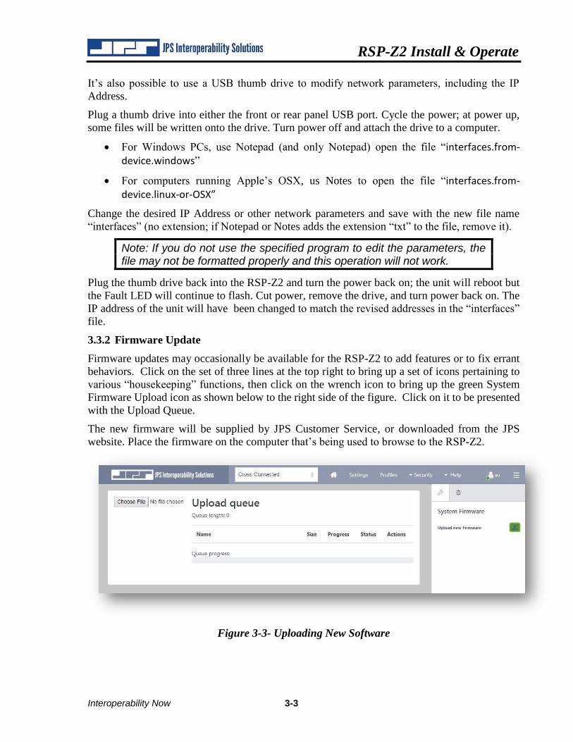
3.3.2 Firmware Update
Firmware updates may occasionally be available for the RSP-Z2 to add features or to fix errant
behaviors. Click on the set of three lines at the top right to bring up a set of icons pertaining to
various “housekeeping” functions, then click on the wrench icon to bring up the green System
Firmware Upload icon as shown below to the right side of the figure. Click on it to be presented
with the Upload Queue.
The new firmware will be supplied by JPS Customer Service, or downloaded from the JPS
website. Place the firmware on the computer that’s being used to browse to the RSP-Z2.
Figure 3-3- Uploading New Software
RSP-Z2 Install & Operate
3-4 Interoperability Now
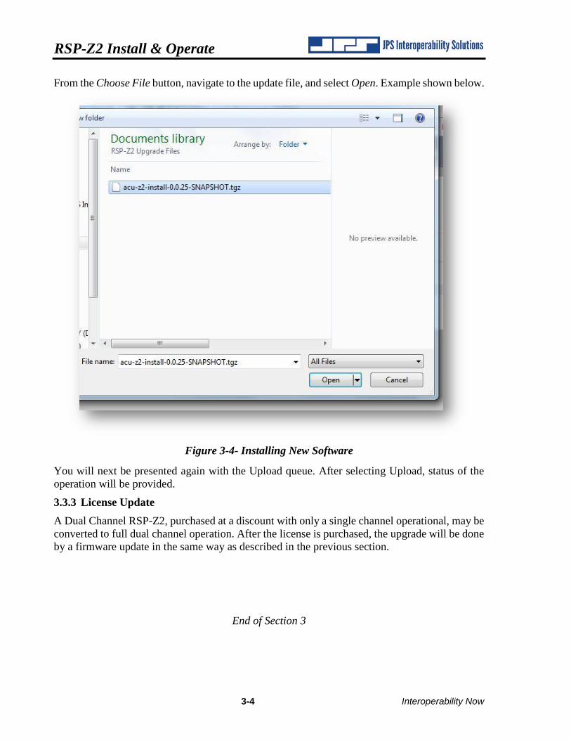
From the Choose File button, navigate to the update file, and select Open. Example shown below.
Figure 3-4- Installing New Software
You will next be presented again with the Upload queue. After selecting Upload, status of the
operation will be provided.
3.3.3 License Update
A Dual Channel RSP-Z2, purchased at a discount with only a single channel operational, may be
converted to full dual channel operation. After the license is purchased, the upgrade will be done
by a firmware update in the same way as described in the previous section.
End of Section 3
RSP-Z2 Install & Operate
Interoperability Now 4-1
4 Security - User Types & Permissions
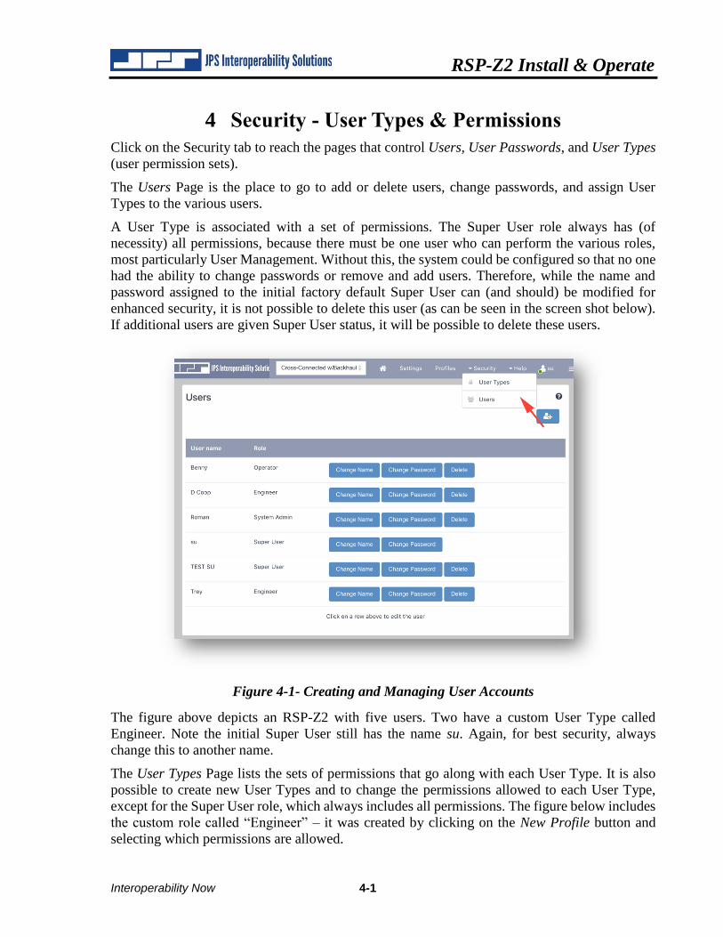
Click on the Security tab to reach the pages that control Users, User Passwords, and User Types
(user permission sets).
The Users Page is the place to go to add or delete users, change passwords, and assign User
Types to the various users.
A User Type is associated with a set of permissions. The Super User role always has (of
necessity) all permissions, because there must be one user who can perform the various roles,
most particularly User Management. Without this, the system could be configured so that no one
had the ability to change passwords or remove and add users. Therefore, while the name and
password assigned to the initial factory default Super User can (and should) be modified for
enhanced security, it is not possible to delete this user (as can be seen in the screen shot below).
If additional users are given Super User status, it will be possible to delete these users.
Figure 4-1- Creating and Managing User Accounts
The figure above depicts an RSP-Z2 with five users. Two have a custom User Type called
Engineer. Note the initial Super User still has the name su. Again, for best security, always
change this to another name.
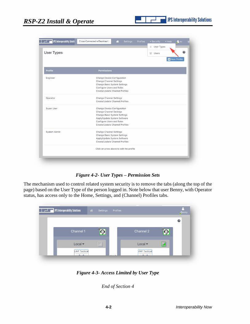
The User Types Page lists the sets of permissions that go along with each User Type. It is also
possible to create new User Types and to change the permissions allowed to each User Type,
except for the Super User role, which always includes all permissions. The figure below includes
the custom role called “Engineer” – it was created by clicking on the New Profile button and
selecting which permissions are allowed.
RSP-Z2 Install & Operate
4-2 Interoperability Now
Figure 4-2- User Types – Permission Sets
The mechanism used to control related system security is to remove the tabs (along the top of the
page) based on the User Type of the person logged in. Note below that user Benny, with Operator
status, has access only to the Home, Settings, and (Channel) Profiles tabs.
Figure 4-3- Access Limited by User Type
End of Section 4
RSP-Z2 Install & Operate
Interoperability Now 5-1
5 RSP-Z2 Configuration
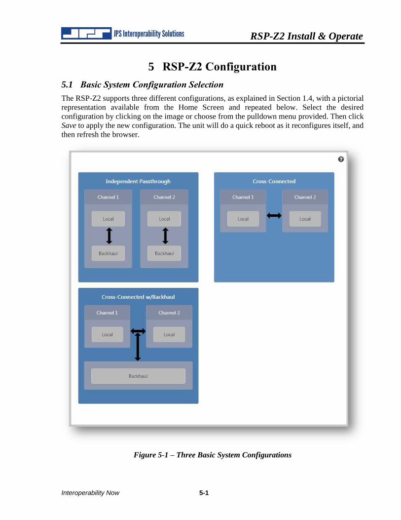
5.1 Basic System Configuration Selection
The RSP-Z2 supports three different configurations, as explained in Section 1.4, with a pictorial
representation available from the Home Screen and repeated below. Select the desired
configuration by clicking on the image or choose from the pulldown menu provided. Then click
Save to apply the new configuration. The unit will do a quick reboot as it reconfigures itself, and
then refresh the browser.
Figure 5-1 – Three Basic System Configurations
RSP-Z2 Install & Operate
5-2 Interoperability Now
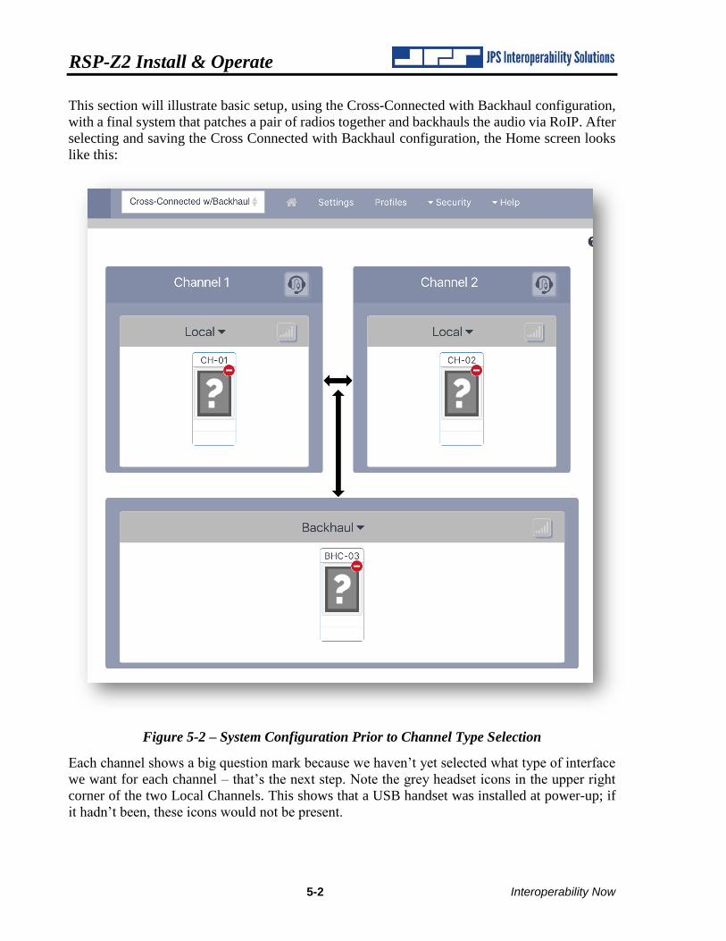
This section will illustrate basic setup, using the Cross-Connected with Backhaul configuration,
with a final system that patches a pair of radios together and backhauls the audio via RoIP. After
selecting and saving the Cross Connected with Backhaul configuration, the Home screen looks
like this:
Figure 5-2 – System Configuration Prior to Channel Type Selection
Each channel shows a big question mark because we haven’t yet selected what type of interface
we want for each channel – that’s the next step. Note the grey headset icons in the upper right
corner of the two Local Channels. This shows that a USB handset was installed at power-up; if
it hadn’t been, these icons would not be present.
RSP-Z2 Install & Operate
Interoperability Now 5-3
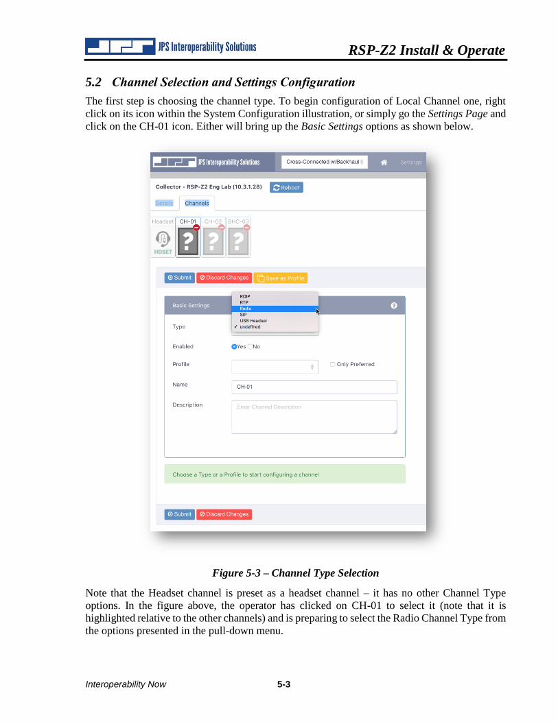
5.2 Channel Selection and Settings Configuration
The first step is choosing the channel type. To begin configuration of Local Channel one, right
click on its icon within the System Configuration illustration, or simply go the Settings Page and
click on the CH-01 icon. Either will bring up the Basic Settings options as shown below.
Figure 5-3 – Channel Type Selection
Note that the Headset channel is preset as a headset channel – it has no other Channel Type
options. In the figure above, the operator has clicked on CH-01 to select it (note that it is
highlighted relative to the other channels) and is preparing to select the Radio Channel Type from
the options presented in the pull-down menu.
RSP-Z2 Install & Operate
5-4 Interoperability Now
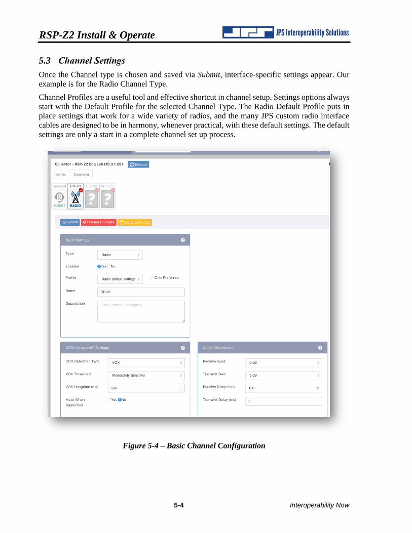
5.3 Channel Settings
Once the Channel type is chosen and saved via Submit, interface-specific settings appear. Our
example is for the Radio Channel Type.
Channel Profiles are a useful tool and effective shortcut in channel setup. Settings options always
start with the Default Profile for the selected Channel Type. The Radio Default Profile puts in
place settings that work for a wide variety of radios, and the many JPS custom radio interface
cables are designed to be in harmony, whenever practical, with these default settings. The default
settings are only a start in a complete channel set up process.
Figure 5-4 – Basic Channel Configuration
RSP-Z2 Install & Operate
Interoperability Now 5-5
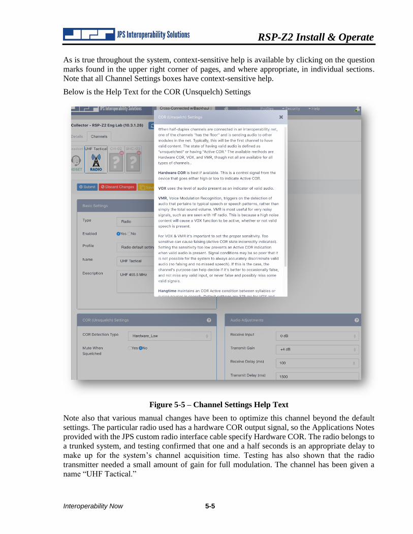
As is true throughout the system, context-sensitive help is available by clicking on the question
marks found in the upper right corner of pages, and where appropriate, in individual sections.
Note that all Channel Settings boxes have context-sensitive help.
Below is the Help Text for the COR (Unsquelch) Settings
Figure 5-5 – Channel Settings Help Text
Note also that various manual changes have been to optimize this channel beyond the default
settings. The particular radio used has a hardware COR output signal, so the Applications Notes
provided with the JPS custom radio interface cable specify Hardware COR. The radio belongs to
a trunked system, and testing confirmed that one and a half seconds is an appropriate delay to
make up for the system’s channel acquisition time. Testing has also shown that the radio
transmitter needed a small amount of gain for full modulation. The channel has been given a
name “UHF Tactical.”
RSP-Z2 Install & Operate
5-6 Interoperability Now
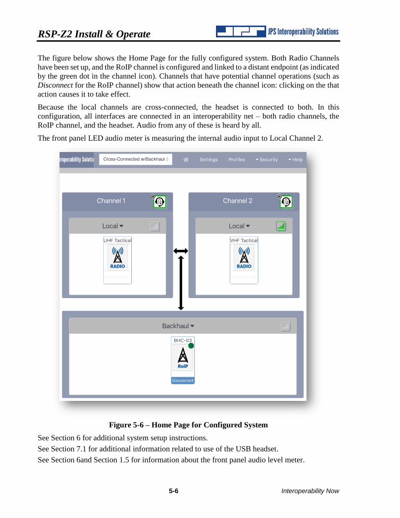
The figure below shows the Home Page for the fully configured system. Both Radio Channels
have been set up, and the RoIP channel is configured and linked to a distant endpoint (as indicated
by the green dot in the channel icon). Channels that have potential channel operations (such as
Disconnect for the RoIP channel) show that action beneath the channel icon: clicking on the that
action causes it to take effect.
Because the local channels are cross-connected, the headset is connected to both. In this
configuration, all interfaces are connected in an interoperability net – both radio channels, the
RoIP channel, and the headset. Audio from any of these is heard by all.
The front panel LED audio meter is measuring the internal audio input to Local Channel 2.
Figure 5-6 – Home Page for Configured System
See Section 6 for additional system setup instructions.
See Section 7.1 for additional information related to use of the USB headset.
See Section 6and Section 1.5 for information about the front panel audio level meter.
RSP-Z2 Install & Operate
Interoperability Now 5-7
5.4 Channel Profiles
A Channel Profile is a predefined template for a channel’s configuration settings.
One Default Profile exists for each channel type. They provide a basic, typical starting point for
all the channel’s settings for which this is possible (e.g., there is no such thing as a typical IP
address). The Default Profiles provide only a good starting point for Channel setup and they are
not intended to constitute a complete setup.
Radio Channel Profiles are particularly important due to the large number of different radio
makes and models available. A set of Radio Profiles for commonly used radios is included
within the unit. Each is made up of the settings that work best for a typical radio of the
designated make/model – as tested by JPS Systems Engineering and as set up per the
instructions in the JPS App Notes included with that cable, when using the JPS cable
designated for that radio.
The App Notes can be vital for proper performance as they may include necessary instructions
for adjusting the radio or modifying radio programming. Additional copies can be downloaded
from the JPS website.
Users may also create their own Custom Profiles. This designation can be useful when a
channel has been optimized for the user’s system. The Custom Profile can be applied to another
channel of the same type for quick identical setup. They can also be kept as a known working
set of configuration settings that can be reapplied after temporary or exploratory settings
changes are made for any reason, such as the need for longer audio delays during periods of
congested radio traffic.
To make important or frequently-used profiles easy to find, some profiles may be designated as
Preferred Profiles. For example, if an agency typically uses four different types of radios,
Preferred Profiles can be created for these four. The system allows a search that saves time by
including only Preferred Profiles.
Channel Profiles come into play on two of the RSP-Z2’s pages, the Channel Settings page and
the Profiles page.
On the Channel Settings page, when a Channel Type is first assigned, the Default Profile for
that type of channel will be applied, along with the settings associated with that Default Profile.
We’ll use Radio Profiles as an example, since profiles are most helpful for radio channels and
many are included in the system database. If the device operator knows the type of radio that is
being interfaced by JPS Custom Cable to the rear panel radio port, the operator can search for
that cable’s profile using the drop-down menu. Note: The only profiles that will show up in any
search are those that correspond to the selected channel type – in this example, Radio Profiles
only. If the operator knows that some Preferred Profiles have been designated, a selection box
allows the profile listing to be limited to Preferred Profiles.
RSP-Z2 Install & Operate
5-8 Interoperability Now
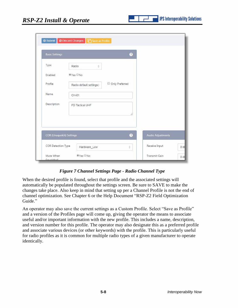
Figure 7 Channel Settings Page - Radio Channel Type
When the desired profile is found, select that profile and the associated settings will
automatically be populated throughout the settings screen. Be sure to SAVE to make the
changes take place. Also keep in mind that setting up per a Channel Profile is not the end of
channel optimization. See Chapter 6 or the Help Document “RSP-Z2 Field Optimization
Guide.”
An operator may also save the current settings as a Custom Profile. Select “Save as Profile”
and a version of the Profiles page will come up, giving the operator the means to associate
useful and/or important information with the new profile. This includes a name, description,
and version number for this profile. The operator may also designate this as a preferred profile
and associate various devices (or other keywords) with the profile. This is particularly useful
for radio profiles as it is common for multiple radio types of a given manufacturer to operate
identically.
RSP-Z2 Install & Operate
Interoperability Now 5-9
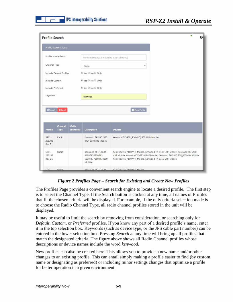
Figure 2 Profiles Page – Search for Existing and Create New Profiles
The Profiles Page provides a convenient search engine to locate a desired profile. The first step
is to select the Channel Type. If the Search button is clicked at any time, all names of Profiles
that fit the chosen criteria will be displayed. For example, if the only criteria selection made is
to choose the Radio Channel Type, all radio channel profiles stored in the unit will be
displayed.
It may be useful to limit the search by removing from consideration, or searching only for
Default, Custom, or Preferred profiles. If you know any part of a desired profile’s name, enter
it in the top selection box. Keywords (such as device type, or the JPS cable part number) can be
entered in the lower selection box. Pressing Search at any time will bring up all profiles that
match the designated criteria. The figure above shows all Radio Channel profiles whose
descriptions or device names include the word kenwood.
New profiles can also be created here. This allows you to provide a new name and/or other
changes to an existing profile. This can entail simply making a profile easier to find (by custom
name or designating as preferred) or including minor settings changes that optimize a profile
for better operation in a given environment.
RSP-Z2 Install & Operate
5-10 Interoperability Now
5.5 Channel Profiles Basic Information
• Profiles are templates of configuration settings for the RSP-Z2 channels and can greatly
speed the setup process. Applying a profile configures the channel to match the profile’s
stored settings.
• Profiles can’t include all settings for every channel, or the optimal settings; additional
setup is required.
• Application of a profile is the best first step in configuring a channel, but further
optimization on an individual channel basis is vital for best operation
• Default Profiles exist for each channel type, and, where possible, configure a channel to
reasonable initial settings.
• A large set of Radio Channel Profiles is included. The profiles conform to the radio
interface cables, sold by JPS, and optimized for use with over 300 radio makes and
models.
• System users can create and save their own Custom Profiles.
• Custom Profiles can be given Preferred status to simplify profile searches.
• Default Profiles and JPS Radio Profiles cannot be deleted or modified. It’s important that
if JPS Customer Service assists with channel setup, there is a known basis. However:
• Custom Profiles can be created that are based on Default Profiles or JPS Radio Profiles,
and modified as desired, but the Custom Profiles cannot replace the Default or JPS Radio
Profiles.
Note: No settings are applied until the Save Configuration button (at the bottom of each Channel Configuration page) is pressed.
RSP-Z2 Install & Operate
Interoperability Now 5-11
5.6 Channel Settings – Universal
The Basic Settings and Audio Priority settings boxes are used with all Channel Types.
5.6.1 Basic Settings
The Basic Settings are universal for all channel types, mainly they define what type of channel
it is, what it will be named, and whether it is currently enabled.
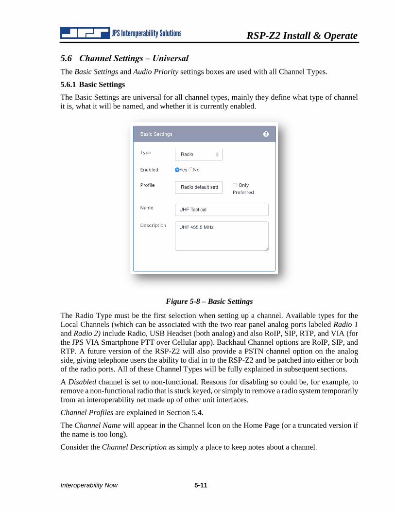
Figure 5-8 – Basic Settings
The Radio Type must be the first selection when setting up a channel. Available types for the
Local Channels (which can be associated with the two rear panel analog ports labeled Radio 1
and Radio 2) include Radio, USB Headset (both analog) and also RoIP, SIP, RTP, and VIA (for
the JPS VIA Smartphone PTT over Cellular app). Backhaul Channel options are RoIP, SIP, and
RTP. A future version of the RSP-Z2 will also provide a PSTN channel option on the analog
side, giving telephone users the ability to dial in to the RSP-Z2 and be patched into either or both
of the radio ports. All of these Channel Types will be fully explained in subsequent sections.
A Disabled channel is set to non-functional. Reasons for disabling so could be, for example, to
remove a non-functional radio that is stuck keyed, or simply to remove a radio system temporarily
from an interoperability net made up of other unit interfaces.
Channel Profiles are explained in Section 5.4.
The Channel Name will appear in the Channel Icon on the Home Page (or a truncated version if
the name is too long).
Consider the Channel Description as simply a place to keep notes about a channel.
RSP-Z2 Install & Operate
5-12 Interoperability Now
5.6.2 Audio Priority
For individual RSP-Z2 units, use the Audio Priority Settings only for a situation like the example
sited below. This feature has much more utility for wide area interoperability systems that include
this RSP-Z2 along with many other JPS Interoperability Solutions radio gateways.
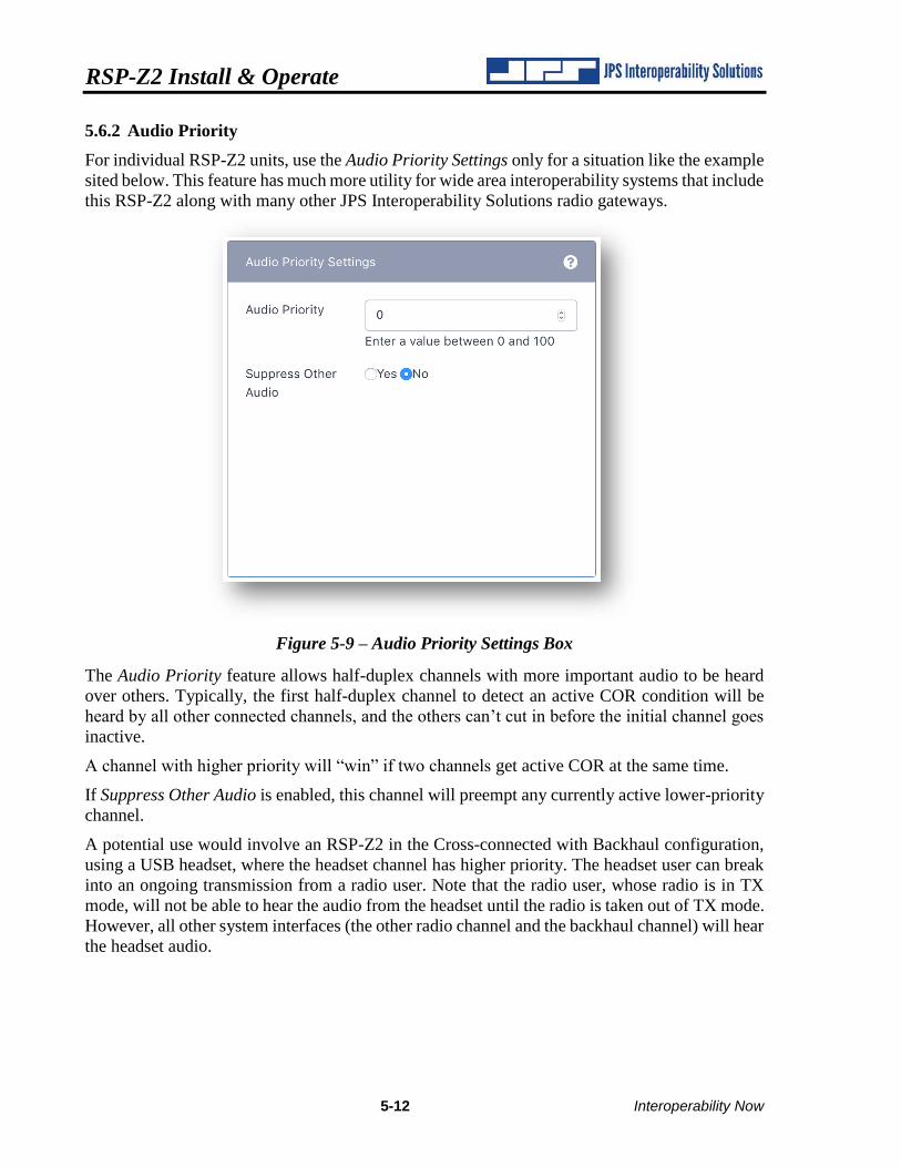
Figure 5-9 – Audio Priority Settings Box
The Audio Priority feature allows half-duplex channels with more important audio to be heard
over others. Typically, the first half-duplex channel to detect an active COR condition will be
heard by all other connected channels, and the others can’t cut in before the initial channel goes
inactive.
A channel with higher priority will “win” if two channels get active COR at the same time.
If Suppress Other Audio is enabled, this channel will preempt any currently active lower-priority
channel.
A potential use would involve an RSP-Z2 in the Cross-connected with Backhaul configuration,
using a USB headset, where the headset channel has higher priority. The headset user can break
into an ongoing transmission from a radio user. Note that the radio user, whose radio is in TX
mode, will not be able to hear the audio from the headset until the radio is taken out of TX mode.
However, all other system interfaces (the other radio channel and the backhaul channel) will hear
the headset audio.
RSP-Z2 Install & Operate
Interoperability Now 5-13
5.7 Local Channel Settings – USB Headset
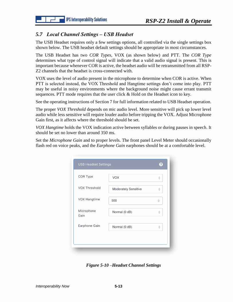
The USB Headset requires only a few settings options, all controlled via the single settings box
shown below. The USB headset default settings should be appropriate in most circumstances.
The USB Headset has two COR Types, VOX (as shown below) and PTT. The COR Type
determines what type of control signal will indicate that a valid audio signal is present. This is
important because whenever COR is active, the headset audio will be retransmitted from all RSP-
Z2 channels that the headset is cross-connected with.
VOX uses the level of audio present in the microphone to determine when COR is active. When
PTT is selected instead, the VOX Threshold and Hangtime settings don’t come into play. PTT
may be useful in noisy environments where the background noise might cause errant transmit
sequences. PTT mode requires that the user click & Hold on the Headset icon to key.
See the operating instructions of Section 7 for full information related to USB Headset operation.
The proper VOX Threshold depends on mic audio level. More sensitive will pick up lower level
audio while less sensitive will require louder audio before tripping the VOX. Adjust Microphone
Gain first, as it affects where the threshold should be set.
VOX Hangtime holds the VOX indication active between syllables or during pauses in speech. It
should be set no lower than around 350 ms.
Set the Microphone Gain and to proper levels. The front panel Level Meter should occasionally
flash red on voice peaks, and the Earphone Gain earphones should be at a comfortable level.
Figure 5-10 –Headset Channel Settings
RSP-Z2 Install & Operate
5-14 Interoperability Now
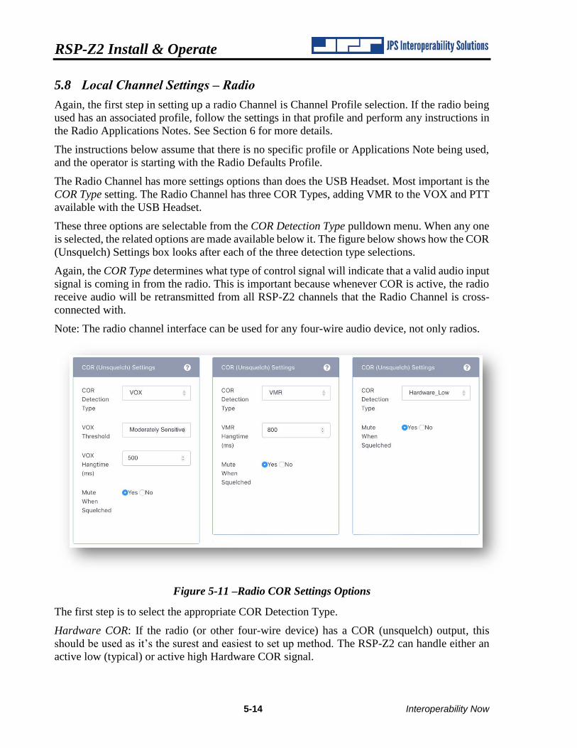
5.8 Local Channel Settings – Radio
Again, the first step in setting up a radio Channel is Channel Profile selection. If the radio being
used has an associated profile, follow the settings in that profile and perform any instructions in
the Radio Applications Notes. See Section 6 for more details.
The instructions below assume that there is no specific profile or Applications Note being used,
and the operator is starting with the Radio Defaults Profile.
The Radio Channel has more settings options than does the USB Headset. Most important is the
COR Type setting. The Radio Channel has three COR Types, adding VMR to the VOX and PTT
available with the USB Headset.
These three options are selectable from the COR Detection Type pulldown menu. When any one
is selected, the related options are made available below it. The figure below shows how the COR
(Unsquelch) Settings box looks after each of the three detection type selections.
Again, the COR Type determines what type of control signal will indicate that a valid audio input
signal is coming in from the radio. This is important because whenever COR is active, the radio
receive audio will be retransmitted from all RSP-Z2 channels that the Radio Channel is cross-
connected with.
Note: The radio channel interface can be used for any four-wire audio device, not only radios.
Figure 5-11 –Radio COR Settings Options
The first step is to select the appropriate COR Detection Type.
Hardware COR: If the radio (or other four-wire device) has a COR (unsquelch) output, this
should be used as it’s the surest and easiest to set up method. The RSP-Z2 can handle either an
active low (typical) or active high Hardware COR signal.
RSP-Z2 Install & Operate
Interoperability Now 5-15
VOX: This COR Detection type uses the level of audio signal present to determine if a valid
signal is present. When a Hardware COR signal is not available, VOX is the best method, as long
as most of the audio coming in consists of speech (or other signal that you want to be detected as
valid).
VMR: Voice Modulation Recognition triggers not simply on the audio level, but on the values of
various speech-related components available within the audio. VMR is the best COR Detection
method for noisy audio, such as is present with HF radio signals. The sophisticated VMR
algorithm takes longer to make a determination of valid audio than does VOX, therefore it
requires additional RX audio delay.
Both VOX & VMR require some hangtime, which maintains COR active between syllables or
pauses in speech. Without hangtime the retransmission of this incoming audio would be choppy.
Differences in the VOX & VMR algorithms necessitate different minimum hangtimes; 180 ms
for VOX and 800 ms for VMR. Minimum allowed hangtime is 3 seconds for each. Default
settings are 500 ms for VOX and 800 ms for VMR. Maximums are 3 seconds for both.
VOX also has a threshold setting. The default setting should typically work, but if incoming
speech doesn’t consistently trip the VOX, increase the sensitivity. If the sensitivity is set too high,
the system may activate on environmental noise.
The Mute When Squelched option determines whether audio is available for monitoring even if
active COR is not detected. This is a future feature option.
The context-sensitive help information provides further information and guides proper
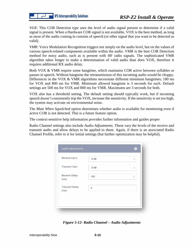
Radio Channel settings also include Audio Adjustments. These vary the levels of the receive and
transmit audio and allow delays to be applied to them. Again, if there is an associated Radio
Channel Profile, refer to it for initial settings (but further optimization may be helpful).
Figure 5-12- Radio Channel – Audio Adjustments
RSP-Z2 Install & Operate
5-16 Interoperability Now
Receive Audio Input adjusts the level of audio coming into the RSP-Z2, with the intention of
raising or lowering to achieve the optimum internal level of approximately 0 dBm. Note that the
level settings for the RSP-Z2 are identical to those of other JPS gateways.
To verify proper setting, set the RSP-Z2 front panel audio level meter for the radio channel being
set up; monitor it and/or the front panel Signal LED for that channel. While receiving audio from
someone speaking at a normal level, the signal level should flash red on occasional voice peaks.
It shouldn’t be lit continuously while speech is coming in, but a normal speaking level should
create occasional flashes. If the incoming speech never causes red flashes, drop the Receive input
level setting until it does. Conversely, if all speech causes red Signal LED flashes, raise the
Receive input level until the flashes are occasional only.
Transmit Gain raises or lowers the nominal 0 dBm TX output audio signal as needed for full
transmitter modulation.
Receive Audio Delay buffers up the incoming audio until the set time passes, and then begins
spooling it out. Its purpose is to hold up incoming audio until the system is ready to use it. Most
important is to hold up the audio until COR Detection can occur, otherwise some of the incoming
audio can be clipped.
Different types of COR Detection require different minimum Receive Audio Delays. There is no
minimum for Hardware COR. The VOX minimum is 100 ms and the 300 is the minimum delay
for VMR mode. These are the default settings also. Maximum allowed delays are
Similarly, the Transmit Audio Delay holds up the outgoing audio until the external system is
ready to use it. A good example is when the donor radio cabled to one of the RSP-Z2 outputs is
part of a trunked radio system (see Figure the illustrations in the overview in Section 1-3). When
this radio is keyed, nothing happens until the trunking system acquires a channel for that
transmission. Transmit Audio Delay should be set long enough to hold up the outgoing audio
until the donor radio has acquired the channel and is ready to transmit it. Similarly, for a
conventional repeated system, a shorter delay is needed; enough to hold up the audio until the
repeater can key up.
See Section 6 for field system optimization instructions.
RSP-Z2 Install & Operate
Interoperability Now 5-17
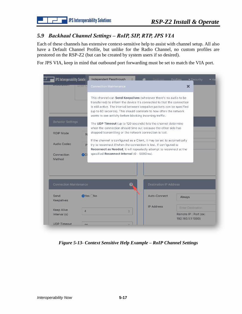
5.9 Backhaul Channel Settings – RoIP, SIP, RTP, JPS VIA
Each of these channels has extensive context-sensitive help to assist with channel setup. All also
have a Default Channel Profile, but unlike for the Radio Channel, no custom profiles are
prestored on the RSP-Z2 (but can be created by system users if so desired).
For JPS VIA, keep in mind that outbound port forwarding must be set to match the VIA port.
Figure 5-13- Context Sensitive Help Example – RoIP Channel Settings
RSP-Z2 Install & Operate
5-18 Interoperability Now
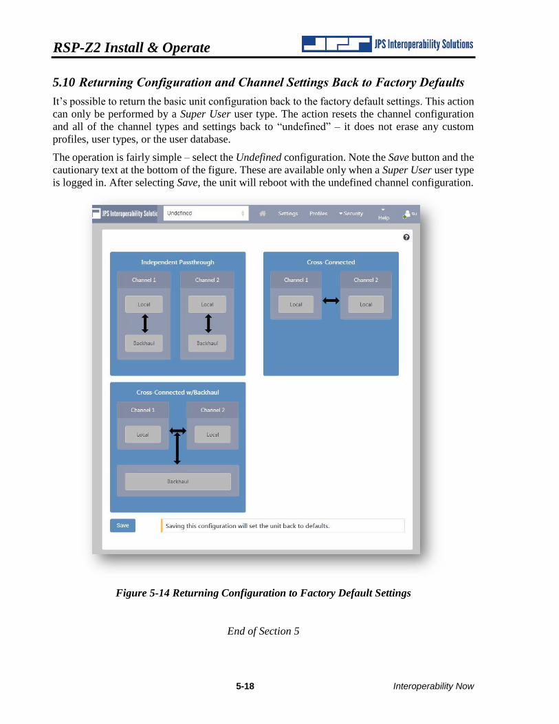
5.10 Returning Configuration and Channel Settings Back to Factory Defaults
It’s possible to return the basic unit configuration back to the factory default settings. This action
can only be performed by a Super User user type. The action resets the channel configuration
and all of the channel types and settings back to “undefined” – it does not erase any custom
profiles, user types, or the user database.
The operation is fairly simple – select the Undefined configuration. Note the Save button and the
cautionary text at the bottom of the figure. These are available only when a Super User user type
is logged in. After selecting Save, the unit will reboot with the undefined channel configuration.
Figure 5-14 Returning Configuration to Factory Default Settings
End of Section 5
RSP-Z2 Install & Operate
Interoperability Now 6-1
6 Field Setup & Optimization
The purpose of this section is to assist with the adjustments and “tweaks” of the analog for best
performance with the varying radio systems encountered in the field.
There are several paths to optimization, based on the following. Most important is:
• Are you using a JPS Custom Radio Interface Cable or creating your own interface cable?
Of lesser importance:
• Are you able to locate a JPS Channel Profile within the RSP-Z2 that corresponds to the
type of radio being interfaced?
• Are you also using one of the Plantronics USB Headsets certified for operation with the
RSP-Z2? See Table 1-4 – Optional Equipment - Not Supplied
Some explanation of these options/paths:
The JPS Custom Radio Interface Cables were designed by JPS Systems Engineers who
investigated the radio’s analog interfaces, then designed an appropriate interface between the
radio and the JPS equipment, and verified it in the lab. Some interfaces are simple, others not so.
Some require DC blocking capacitors or unusual level-setting networks. The JPS cables include
a small circuit board that contains every type of matching/interface network ever required while
interfacing hundreds of different radio makes & models.
Along with each JPS radio interface cable is an Applications Note specific to the type or types
of radios associated with that cable. The Application Note lists the basic settings to optimize the
interface within the JPS equipment in tandem with the cable. Just as importantly, it lists any radio
programming, or switch/level settings required at the radio for proper operation. It is always the
best option for interfacing a radio to the RSP-Z2 or other JPS equipment
The JPS Channel Profiles speed this process by automatically setting the RSP-Z2’s radio
interface configuration options to those listed in the Application Notes that accompany the cable.
These settings are only correct when using the JPS cable. Note: Users can also create & save
their own profiles.
A USB Headset can be helpful because it can be used when setting up any other interface – a
known good interface (the headset) to a (yet unproven) interface. For example, assume there a
problem is encountered when interfacing a pair of radios to the RSP-Z2, or interfacing a radio to
an RoIP backhaul channel. Use of the headset, connected individually to each of the channels in
turn, will quickly identify the problematic channel. Best is to initially set up and optimize each
channel while it’s connected to just the headset – and only then connect the other two (now fully
proven) channels to each other.
It’s easy to see how the headset can help, particularly if difficulties are experienced, but it is
certainly not required.
RSP-Z2 Install & Operate
6-2 Interoperability Now
6.1 Radio Interface Using JPS Custom Radio Cables
This section will assume that a JPS radio interface cable is used. See the next section if not.
The cable should easily connect to the radio; many are built by splicing a cable manufactured for
the specific radio to the appropriate signal lines on the JPS cable.
Follow the instructions of the Application Notes that came with the cable. If the notes are missing,
simply download a new set from the JPS Interoperability Solutions website. Included in the
Application Notes are:
• Configuration settings for the Radio Channel, optimized for the JPS Cable when used
with the associated radio. Note that Applications Notes were created for use with a variety
of JPS gateways; pay attention only to the configuration settings available on the RSP-
Z2 Radio Channel Settings Page.
• Changes that may be required or suggested for the radio itself; either in its configuration
or programming.
If you apply the Channel Profile for the radio, the profile will automatically apply the appropriate
configuration settings.
Next step is to take care of optimization and/or settings that must be set in the field. Most of the
following are best accomplished using a test count from another radio that’s communication with
the donor radio cabled to the RSP-Z2. Listen in a USB headset or to another device cross-
connected via the RSP-Z2 with the donor radio.
6.1.1 RX Audio Level (Receive Input):
Some minor adjustment may be required, mainly due to radio-to-radio variations. A way to
make sure the level is correct is to:
• Associate the RSP-Z2 Front Panel Level meter with the donor radio interface.
• Use a second radio to communicate with the donor radio. Speak into the microphone of
that radio in a normal voice level. The RSP-Z2 level meter should flash its red (top) LEDs
occasionally on voice peaks. Adjust if it never or constantly flashes red.
• Note: The Receive Input levels in the RSP-Z2 GUI indicate the actual level of audio being
received. If the incoming level is -12 dBm, the Receive Input setting of the Radio Channel
should be set to -12dB. This must be understood to know which way to change the audio
level for proper operation. If the Radio Channel, when set to -12 dB, is not receiving
enough audio, the number in the GUI must be set to a lower number to correspond to the
actual input level. The RSP-Z2 will then apply additional gain/reduced attenuation
6.1.2 TX Audio Level (Transmit Gain):
Set to properly modulate the donor radio transmitter. Audio coming from the donor radio, when
doing a normal voice volume radio count, should be heard in the field radio at the same level as
received conversations from other radios in the system (as heard in the field radio).
• If you have a headset, cross-connect it with the radio interface so that speaking into the
headset causes the donor radio to transmit.
RSP-Z2 Install & Operate
Interoperability Now 6-3
• If you do not have a headset, the you will need to cross connect another channel that has
its RX audio level properly set up (the second radio channel, or a backhaul channel.
Note: Doing the RX level adjustment before setting the TX audio level (or using a headset) and
verifying it via the level meter will help prevent a mutually-erroneous condition where a too-low
RX audio input is compensated by a too-high TX audio input on a cross-connected channel. This
condition is particularly troubling whenever a third interface is introduced to the system – its
incoming audio will be too low for one of the mutually erroneous interfaces and too high for the
other.
6.1.3 VOX or VMR threshold:
Either threshold may benefit from optimization (either more or less sensitive) due to system
variations or user preferences. More sensitive means less audio level (VOX) or characteristics
related to human speech (VMR) must be detected for the incoming audio to be declared valid.
Less sensitive is of course the opposite. Increased sensitivity makes it more likely that falsing
(declaring the input valid when it is not) will occur; decreased sensitivity increases the potential
that valid speech may be missed. Changes may be desired due to level of static on the channel,
quiet talkers, or desire to never miss any audio, even if some falsing occurs.
6.1.4 Transmit Audio Delay
If the donor radio is used with a trunked radio system, it may be necessary to adjust the TX audio
delay. If initial syllables are missing in the RX audio of the field radio (when listening to
transmissions from the RSP-Z2/donor radio) increase the TX audio delay of RSP-Z2 analog
interface connected to that donor radio.
Explanation: When a radio user initiates a transmit sequence for a trunked radio, that user
depresses the PTT switch on the radio, which sends a signal to the system’s trunking controller,
asking to be assigned to a free (not currently busy) channel. The trunking controller sends a signal
back to the user’s radio that automatically sets the radio to a free channel, and signals this to the
radio user by tone called a channel acquisition tone or simply a go-ahead tone. The trunked
system radio user is trained to not begin talking until this tone is heard.
Unfortunately, this tone can’t be heard by users on other systems that are cross-connected by the
RSP-Z2 to the trunked radio system. They simply begin talking, if n a non-radio device, or if
using a non-trunked radio, they simply press PTT and begin talking. TX audio delay on the donor
trunked radio channel holds up the audio, storing it in a buffer, until enough time has gone by for
a typical channel acquisition time to have elapsed. See Section 1 of the Operations and
Installation manual for a more complete explanation, including diagrams.
This test is best done when talking into a USB headset that is cross-connected with the radio
interface. The reason is that use of the headset precludes any chance that any audio is missing
initial syllables before being sent to the donor radio to be transmitted to the trunking system.
RX Audio Delay must be increased if initial syllables are clipped on incoming audio of a Radio
Channel; see below. If you are using a cross-connected radio channel instead of a headset, and
additional increases in TX Audio Delay have no effect on missed first syllables in the field radio,
then it may be necessary to increase the RX Audio Delay in that cross-connected Radio Channel.
An uncommon but possible condition.
RSP-Z2 Install & Operate
6-4 Interoperability Now
6.1.5 RX Audio Delay
Delay in the RX audio occurs by processing the COR detection immediately, but holding the
incoming audio in a buffer and spooling it out after the set delay time. This resolves the
(uncommon) condition for a Radio Channel where the COR indication or detection occurs late
and initial incoming syllables are therefore clipped.
The RSP-Z2 Radio Channel interfaces are designed to prevent this as well a practical, through
proper design of the various COR Detection algorithms and by including a minimum 100ms RX
Audio Delay, but additional delay can be added if needed.
6.1.6 Audio Levels and Delays for Transport Channels
There are no associated configuration options for RX or TX level settings, or to change RX or
TX audio delays for the digital transport channels – RoIP, SIP, RTP, VIA. These channels send
the digital representation of the audio signal at whatever level it was in the sending (TX) side.
Modifying the levels or delays is done at the audio input or output channels.
For example, if a pair of RSP-Z2s is used to connect radios via IP that are on opposite sides of
the world, if the RX input of each radio is correct, the level received by the distant radio on the
other side of the RoIP link will be correct
6.2 Radio Interface Using Customer-Designed Radio Cables
For customers who plan to create their own radio interface cables, JPS strongly recommends
using the Unterminated Radio Cable, JPS P/N 5961-291115. This shielded cable includes the
D15 end of the cable that plugs into either of the RSP-Z2 analog ports, along with the small PCB
that’s in other JPS cables – this circuitry has a variety of variable attenuating, terminating and
DC-blocking components; essentially everything that JPS Systems Engineers have deemed
necessary to interface any of the several hundred types of radios they have created custom cables
for. This seven-pin cable is unterminated on the radio side, allowing radio specific portion of the
cable to be spliced on.
The Application Notes for this cable, available for download like all other JPS Custom Radio
Cables Application Notes, contains information to help in the cable design and, in particular,
explains how to determine which of the various configuration options is best (e.g. how to decide
how to choose between the COR options of VOX, VMR, or Hardware COR?).
This useful information will not be repeated in this document.
Note: Older versions of the Unterminated Radio Cable Application Notes relate to its use with
the ACU-1000 or ACU-T gateways. All relevant information applies to the RSP-Z2.
RSP-Z2 Install & Operate
Interoperability Now 6-5
6.3 Radio Interface Troubleshooting Tips
6.3.1 Symptom: User in Field Complains of Missed First Syllables
Cause: Donor radio is trunked, need to compensate for Channel Acquisition Delay
Cause: Slow-to-key transmitter on donor radio
Cause: Secure donor radio, need to compensate for encryption or scrambling
Solution: Increase TRANSMIT AUDIO DELAY of the RSP-Z2 Radio Channel supporting the
donor radio
6.3.2 Symptom: User in Field Complains of Missed Syllables Mid-Conversation
Cause: Dropout from Radio Channel using VOX or VMR COR Detection Type
Solution: Increase VOX or VMR HANGTIME of the Radio Channel supporting the donor radio
Solution: Increase VOX or VMR THRESHOLD of the Radio Channel supporting the donor radio
6.3.3 Symptom: Continuous Ping-Pong of COR / PTT between Cross Connected Radios
Cause: “Ping-Pong” is caused by the tendency of some radios to temporarily unsquelch at the
end of a transmit sequence. This momentary Active COR condition in a donor radio (Radio 1)
will cause a momentary transmit sequence in any devices that are cross-connected to that donor
radio. If one of the cross-connected devices is another donor radio (Radio 2) with the same
“momentary unsquelch at the end of a transmit sequence, then the Radio 1 momentary unsquelch
keys Radio 2, whose resulting momentary unsquelch keys radio one in a continuing sequence.
Solution: Change COR DETECTION TYPE to VMR
6.3.4 Symptom: False Keying of Donor Radio by Radio Channel
Cause: Extraneous RFI emissions present at frequency/level that keys a donor radio
Solution: Eliminate RFI emission source
Solution: Transit power of other, nearby donor radios may be excessive, so if possible. reduce to
just enough to link to repeater
Solution: Modify antenna placement
Solution: Change COR DETECTION TYPE to VMR
6.3.5 Symptom: Radio Channel Experiencing Continuous Active COR State
Cause: Donor radio is introducing continuous noise to Radio Channel
Cause: Donor radio is an unsquelchable Amplitude Modulated receiver (i.e. HF, aircraft radio,
etc.)
Solution: Change COR DETECTION TYPE to VMR
RSP-Z2 Install & Operate
6-6 Interoperability Now
6.3.6 Symptom: Audio Sounds Too Weak
Cause: Received audio level from donor radio (or other device type) is too low; verify using RSP-
Z2 front panel Level meter.
Solution: Change RECEIVE INPUT audio setting of the receiving Radio Channel (or other type
of channel) until RSP-Z2 front panel Level meter red LEDs flicker with voice peaks of incoming
speech. Note: The number in the RSP-Z2 GUI indicates the actual level of audio being received.
If the incoming level is -12 dBm, the Receive Input setting of the Radio Channel should be set
to -12dB. This must be understood to know which way to change the audio level for proper
operation. If the Radio Channel, when set to -12 dB, is not receiving enough audio, the number
in the GUI must be set to a lower number to correspond to the actual input level. The RSP-Z2
will then apply additional gain/reduced attenuation.
Cause: Transmit audio level delivered to donor radio is too low (verify/rectify cause above first!)
Solution: Increase TRANSMIT GAIN of transmitting Radio Channel until donor radio is
properly modulated.
6.3.7 Symptom: Audio Sounds Too Loud or Distorted
Cause: Receive audio level from donor radio (or other device) is too high.
Solution: Change RECEIVE INPUT audio setting of the receiving Radio Channel (or other type
of channel) until RSP-Z2 front panel Level meter red LEDs only flicker with voice peaks of
incoming speech; not on at all times when speech is being received. Note: The number in the
RSP-Z2 GUI indicates the actual level of audio being received. If the incoming level is -12 dBm,
the Receive Input setting of the Radio Channel should be set to -12dB. This must be understood
to know which way to change the audio level for proper operation. If the Radio Channel, when
set to -12 dB, is receiving too much audio, the number in the GUI must be set to a higher number
to correspond to the actual input level. The RSP-Z2 will then apply less gain/more attenuation.
Cause: Transmit audio level delivered to donor radio too high (verify/rectify cause above first!)
Solution: Lower the TRANSMIT GAIN of transmitting Radio Channel until donor radio is
properly modulated.
End of Section 6
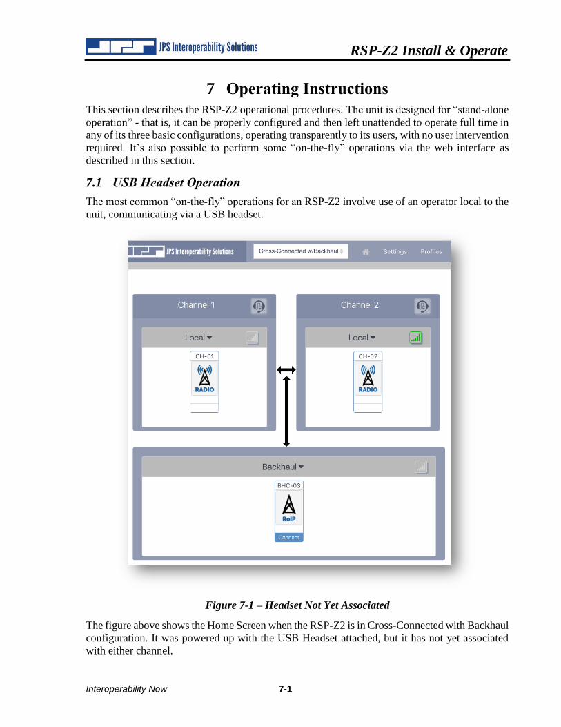
RSP-Z2 Install & Operate
Interoperability Now 7-1
7 Operating Instructions
This section describes the RSP-Z2 operational procedures. The unit is designed for “stand-alone
operation” - that is, it can be properly configured and then left unattended to operate full time in
any of its three basic configurations, operating transparently to its users, with no user intervention
required. It’s also possible to perform some “on-the-fly” operations via the web interface as
described in this section.
7.1 USB Headset Operation
The most common “on-the-fly” operations for an RSP-Z2 involve use of an operator local to the
unit, communicating via a USB headset.
Figure 7-1 – Headset Not Yet Associated
The figure above shows the Home Screen when the RSP-Z2 is in Cross-Connected with Backhaul
configuration. It was powered up with the USB Headset attached, but it has not yet associated
with either channel.
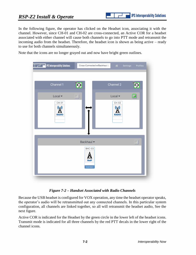
RSP-Z2 Install & Operate
7-2 Interoperability Now
In the following figure, the operator has clicked on the Headset icon, associating it with the
channel. However, since CH-01 and CH-02 are cross-connected, an Active COR for a headset
associated with either channel will cause both channels to go into PTT mode and retransmit the
incoming audio from the headset. Therefore, the headset icon is shown as being active – ready
to use for both channels simultaneously.
Note that the icons are no longer grayed out and now have bright green outlines.
Figure 7-2 – Handset Associated with Radio Channels
Because the USB headset is configured for VOX operation, any time the headset operator speaks,
the operator’s audio will be retransmitted out any connected channels. In this particular system
configuration, all channels are linked together, so all will retransmit the headset audio, See the
next figure.
Active COR is indicated for the Headset by the green circle in the lower left of the headset icons.
Transmit mode is indicated for all three channels by the red PTT decals in the lower right of the
channel icons.
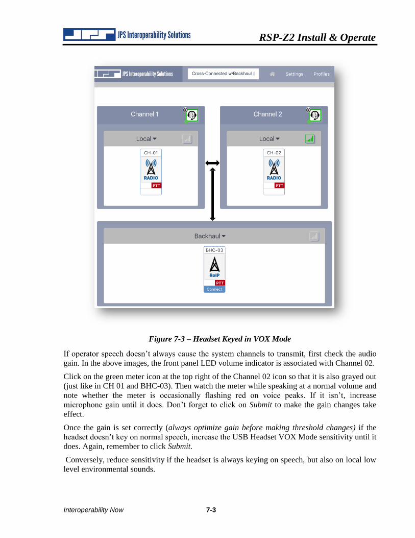
RSP-Z2 Install & Operate
Interoperability Now 7-3
Figure 7-3 – Headset Keyed in VOX Mode
If operator speech doesn’t always cause the system channels to transmit, first check the audio
gain. In the above images, the front panel LED volume indicator is associated with Channel 02.
Click on the green meter icon at the top right of the Channel 02 icon so that it is also grayed out
(just like in CH 01 and BHC-03). Then watch the meter while speaking at a normal volume and
note whether the meter is occasionally flashing red on voice peaks. If it isn’t, increase
microphone gain until it does. Don’t forget to click on Submit to make the gain changes take
effect.
Once the gain is set correctly (always optimize gain before making threshold changes) if the
headset doesn’t key on normal speech, increase the USB Headset VOX Mode sensitivity until it
does. Again, remember to click Submit.
Conversely, reduce sensitivity if the headset is always keying on speech, but also on local low
level environmental sounds.
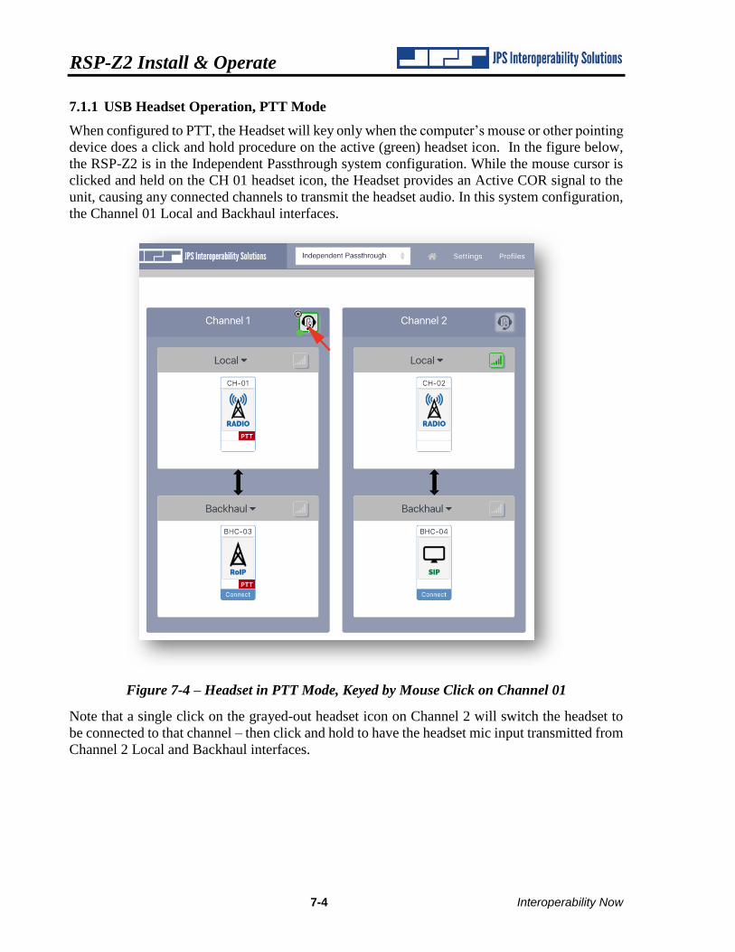
RSP-Z2 Install & Operate
7-4 Interoperability Now
7.1.1 USB Headset Operation, PTT Mode
When configured to PTT, the Headset will key only when the computer’s mouse or other pointing
device does a click and hold procedure on the active (green) headset icon. In the figure below,
the RSP-Z2 is in the Independent Passthrough system configuration. While the mouse cursor is
clicked and held on the CH 01 headset icon, the Headset provides an Active COR signal to the
unit, causing any connected channels to transmit the headset audio. In this system configuration,
the Channel 01 Local and Backhaul interfaces.
Figure 7-4 – Headset in PTT Mode, Keyed by Mouse Click on Channel 01
Note that a single click on the grayed-out headset icon on Channel 2 will switch the headset to
be connected to that channel – then click and hold to have the headset mic input transmitted from
Channel 2 Local and Backhaul interfaces.
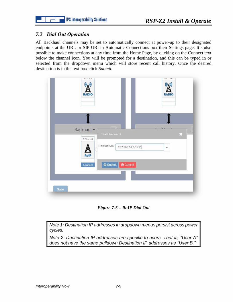
RSP-Z2 Install & Operate
Interoperability Now 7-5
7.2 Dial Out Operation
All Backhaul channels may be set to automatically connect at power-up to their designated
endpoints at the URL or SIP URI in Automatic Connections box their Settings page. It’s also
possible to make connections at any time from the Home Page, by clicking on the Connect text
below the channel icon. You will be prompted for a destination, and this can be typed in or
selected from the dropdown menu which will store recent call history. Once the desired
destination is in the text box click Submit.
Figure 7-5 – RoIP Dial Out
Note 1: Destination IP addresses in dropdown menus persist across power cycles.
Note 2: Destination IP addresses are specific to users. That is, “User A” does not have the same pulldown Destination IP addresses as “User B.”
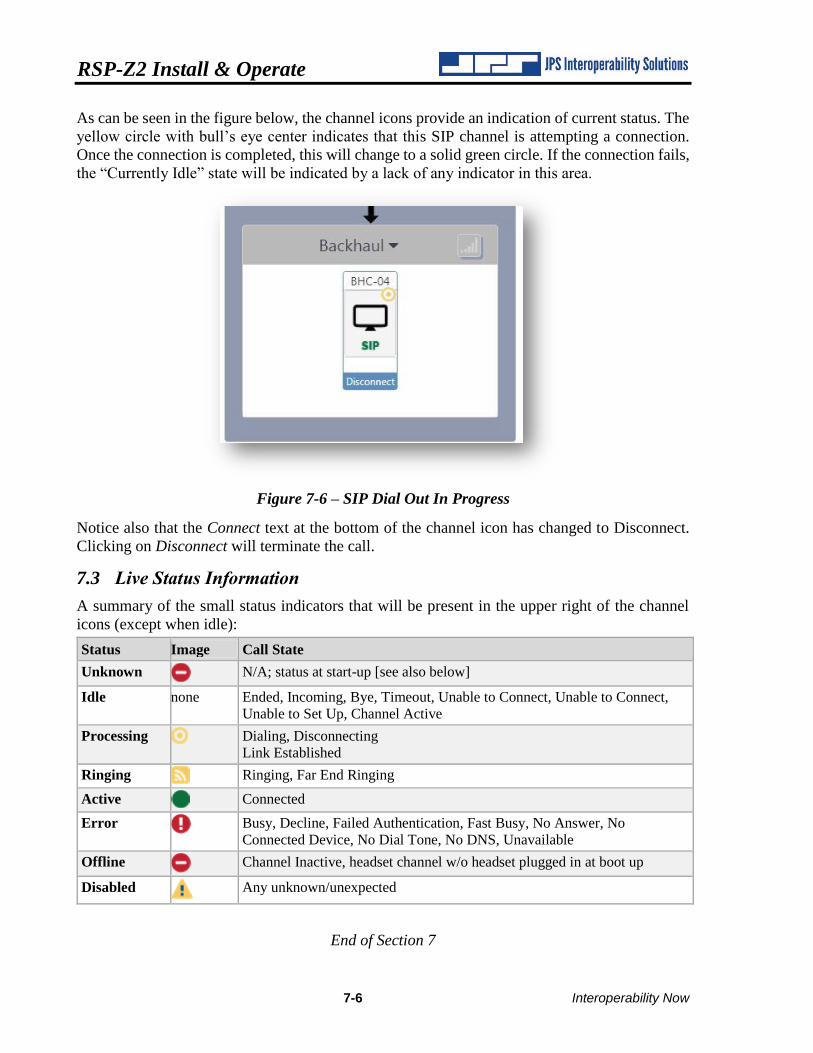
RSP-Z2 Install & Operate
7-6 Interoperability Now
As can be seen in the figure below, the channel icons provide an indication of current status. The
yellow circle with bull’s eye center indicates that this SIP channel is attempting a connection.
Once the connection is completed, this will change to a solid green circle. If the connection fails,
the “Currently Idle” state will be indicated by a lack of any indicator in this area.
Figure 7-6 – SIP Dial Out In Progress
Notice also that the Connect text at the bottom of the channel icon has changed to Disconnect.
Clicking on Disconnect will terminate the call.
7.3 Live Status Information
A summary of the small status indicators that will be present in the upper right of the channel
icons (except when idle):
Status Image Call State
Unknown N/A; status at start-up [see also below]
Idle none Ended, Incoming, Bye, Timeout, Unable to Connect, Unable to Connect,
Unable to Set Up, Channel Active
Processing Dialing, Disconnecting
Link Established
Ringing Ringing, Far End Ringing
Active Connected
Error Busy, Decline, Failed Authentication, Fast Busy, No Answer, No
Connected Device, No Dial Tone, No DNS, Unavailable
Offline Channel Inactive, headset channel w/o headset plugged in at boot up
Disabled
Any unknown/unexpected
End of Section 7
RSP-Z2 Install & Operate
Interoperability Now 8-1
8 Recent Upgrades to the RSP-Z2
This section lists and explains updates and new features that have not yet been fully integrated
into the text of this Operations Manual. These upgrades may result in differences in the current
RSP-Z2 web pages from what has provided in previous chapters. Additional improvements may
have been made that are not included in this section.
8.1 New/Updated Features
This version of the Operations Manual is fully up to date at the time of its release, corresponding
with RSP-Z2 firmware version 1.0.

RSP-Z2 Install & Operate
8-2 Interoperability Now
End of Document