Embed Size (px)
Citation preview
www.solpal.us
Installation and operating manualInstrucciones de montaje
EN
ES
ES
I
2 SOLPAL – SOLAR DESIGN SOLUTIONS
Contents Solpal L / MÍndice
• Safetyinstruction......................................................... 3Instrucciones de seguridad ....................................................... 4
• OverviewofMaterials..................................................5Lista de materiales
• Explanationofsymbols...............................................6Lista de materiales
• SolpalL ............................................................................................7• SolpalM ..........................................................................................8
• SpecificationsforWaterQuality ......................................... 7Datos sobre la calidad del agua
• HydraulicConnection ............................................................. 9Conexión hidráulica
• FlatRoofInstallation..................................................15Montaje en tejado plano
• On-RoofInstallation ............................................................... 21Montaje paralelo sobre tejado
• EnglishInstallation Instructions .............................................................. 23 Warranty ........................................................................................... 24 Operating Instructions ................................................................ 25
• EspañolIndicaciones para el montaje .................................................... 27 Garantía ........................................................................................... 28 Notas sobre el funcionamiento ................................................ 29
• Appendix/apèndice.................................................. 30
SOLPAL – SOLAR DESIGN SOLUTIONS 3
SAFETY INSTRUCTIONS
USERMUSTBEINCOMPLIANCEWITHALLAPPLICABLE
FEDERAL,STATE,ANDMUNICIPALBUILDINGANDFIRE
SAFETYLAWS,CODES,ANDREGULATIONS.
CHECKTHEUNITANDTHEACCESSORIESFORANYVIS-
IBLEDEFECTS,CRACKS,OROTHERDAMAGESAFTERUN-
PACKINGANDBEFOREFIRSTUSE.IFYOUSEEANYDAM-
AGE,DONOTUSETHEPRODUCT.CONTACTCUSTOMER
SERVICEFORHELP.CAREFULLYREADINSTALLATION
INSTRUCTIONSBEFOREYOUINSTALLTHEPRODUCT.
ONLYOPERATETHEPRODUCTAFTERPROPERANDCOM-
PLETEINSTALLATIONANDASSEMBLY.
THESOLPALSYSTEMINCLUDINGITSPIPESMUSTNOTBE
INSTALLEDNEXTTOAPOWEROUTLET.KEEPASAFETY
CLEARANCEDISTANCEOFATLEAST3INCHESBETWEEN
THEUNITASWELLASITSPIPESANDACCESSORIESAND
ANYPOWEROUTLETS.
CAUTION!THESOLPALSYSTEMANDITSPIPESAND
ACCESSORIESCANREACHTEMPERATURESOFUPTO212
DEGREESFAHRENHEIT.DONOTTOUCHANYPARTSOF
THESOLPALSYSTEM,ITSPIPESORITSACCESSORIES
DURINGOPERATIONORWHENTHESOLPALISEXPOSED
TOSUNLIGHT.
ASSURETHATMINORSUNDERTHEAGEOF18,OR
PERSONSWITHREDUCEDPHYSICAL,SENSORYOR
MENTALABILITIESDONOTHAVEACCESSTOTHESOLPAL
SYSTEM.ASSURETHATTHESOLPALISNOTINDIRECT
CONTACTWITHANYITEMSSUCHASLEAVES,TWIGS,
FLAMMABLEMATERIALS,CABLES,OROTHERMATERI-
ALS.KEEPASAFETYCLEARANCEOFATLEAST5FEET
FROMAIRCONDITIONINGSYSTEMS,HEATERS(HVAC
eqipment),SATELLITEDISHESORANYOTHERELEC-
TRONICDEVICES.
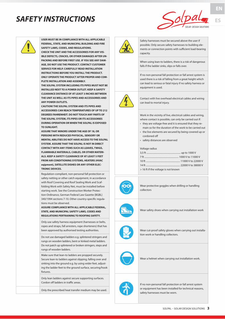
Regulation-compliant, non-personal fall protection or safety netting or other catch equipment, in accordance with Roof Covering and Roof Sealing Work and Scaf-folding Work with Safety Net, must be installed before starting work. See the Construction Worker Protec-tion Ordinance, German Federal Law Gazette [BGBL] 340/1994 sections 7-10. Other country-specific regula-tions must be observed.ASSURECOMPLIANCEWITHALLAPPLICABLEFEDERAL,
STATE,ANDMUNICIPALSAFETYLAWS,CODESAND
REGULATIONSPERTRAININGTOROOFINGSAFETY.
Only use safety harness equipment (harnesses or belts, ropes and straps, fall arresters, rope shorteners) that has been approved by authorised testing authorities.
Do not use damaged ladders e.g. splintered stringers and rungs on wooden ladders, bent or kinked metal ladders. Do not patch up splintered or broken stringers, steps and rungs of wooden ladders.
Make sure that lean-to ladders are propped securely. Secure lean-to ladders against slipping, falling over and sinking into the ground e.g. by using wider feet, adjust-ing the ladder feet to the ground surface, securing/hook fixtures.
Only lean ladders against secure supporting surfaces. Cordon off ladders in traffic areas.
Only the prescribed heat transfer medium may be used.
Safety harnesses must be secured above the user if possible. Only secure safety harnesses to building ele-ments or connection points with sufficient load-bearing capacity.
When using lean-to ladders, there is a risk of dangerous falls if the ladder sinks, slips or falls over.
If no non-personal fall protection or fall arrest system is used there is a risk of falling from a great height which can lead to serious or fatal injury if no safety harness or equipment is used.
Contact with live overhead electrical cables and wiring can lead to mortal injury.
Work in the vicinity of live, electrical cables and wiring, where contact is possible, can only be carried out if: • they are voltage-free and it is ensured that they re-
main so for the duration of the work to be carried out• the live elements are secured by being covered up or
cordoned off• safety distances are observed
Voltage radius3,5 ft .......................................................... up to 1000 V7 ft .......................................................... 1000 V to 11000 V10 ft .......................................................... 11000 V to 22000 V14 ft .......................................................... 22000 V to 38000 V> 16 ft if the voltage is not known
Wear protective goggles when drilling or handling collectors
Wear safety shoes when carrying out installation work
Wear cut-proof safety gloves when carrying out installa-tion work or handling collectors.
Wear a helmet when carrying out installation work.
If no non-personal fall protection or fall arrest system or equipment has been installed for technical reasons, safety harnesses must be worn.
EN
ES
4 SOLPAL – SOLAR DESIGN SOLUTIONS
EN
ES Instrucciones de seguridad
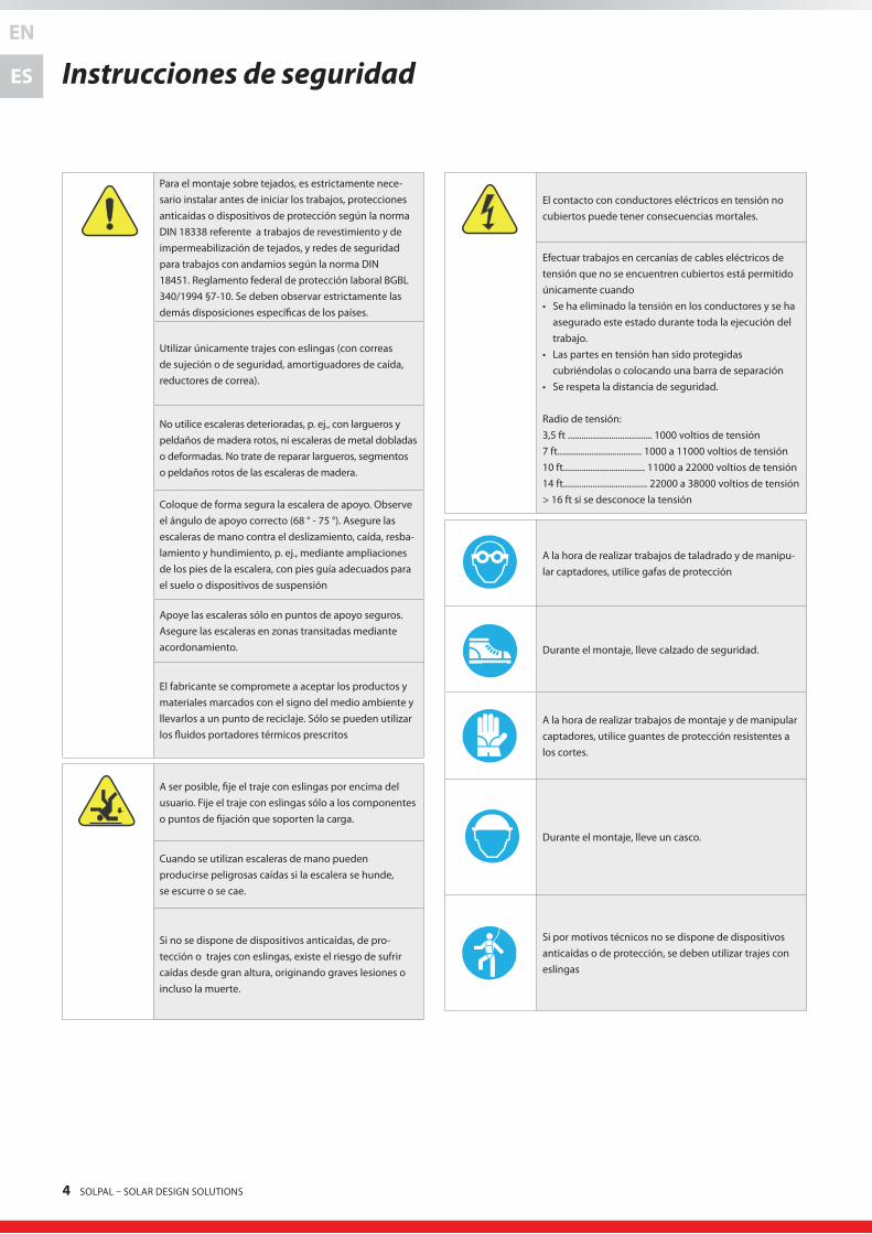
Para el montaje sobre tejados, es estrictamente nece-sario instalar antes de iniciar los trabajos, protecciones anticaídas o dispositivos de protección según la norma DIN 18338 referente a trabajos de revestimiento y de impermeabilización de tejados, y redes de seguridad para trabajos con andamios según la norma DIN 18451. Reglamento federal de protección laboral BGBL 340/1994 §7-10. Se deben observar estrictamente las demás disposiciones específicas de los países.
Utilizar únicamente trajes con eslingas (con correas de sujeción o de seguridad, amortiguadores de caída, reductores de correa).
No utilice escaleras deterioradas, p. ej., con largueros y peldaños de madera rotos, ni escaleras de metal dobladas o deformadas. No trate de reparar largueros, segmentos o peldaños rotos de las escaleras de madera.
Coloque de forma segura la escalera de apoyo. Observe el ángulo de apoyo correcto (68 ° - 75 °). Asegure las escaleras de mano contra el deslizamiento, caída, resba-lamiento y hundimiento, p. ej., mediante ampliaciones de los pies de la escalera, con pies guía adecuados para el suelo o dispositivos de suspensión
Apoye las escaleras sólo en puntos de apoyo seguros. Asegure las escaleras en zonas transitadas mediante acordonamiento.
El fabricante se compromete a aceptar los productos y materiales marcados con el signo del medio ambiente y llevarlos a un punto de reciclaje. Sólo se pueden utilizar los fluidos portadores térmicos prescritos
A ser posible, fije el traje con eslingas por encima del usuario. Fije el traje con eslingas sólo a los componentes o puntos de fijación que soporten la carga.
Cuando se utilizan escaleras de mano pueden producirse peligrosas caídas si la escalera se hunde, se escurre o se cae.
Si no se dispone de dispositivos anticaídas, de pro-tección o trajes con eslingas, existe el riesgo de sufrir caídas desde gran altura, originando graves lesiones o incluso la muerte.
El contacto con conductores eléctricos en tensión no cubiertos puede tener consecuencias mortales.
Efectuar trabajos en cercanías de cables eléctricos de tensión que no se encuentren cubiertos está permitido únicamente cuando • Se ha eliminado la tensión en los conductores y se ha
asegurado este estado durante toda la ejecución del trabajo.
• Las partes en tensión han sido protegidas cubriéndolas o colocando una barra de separación
• Se respeta la distancia de seguridad.
Radio de tensión:3,5 ft ..................................... 1000 voltios de tensión7 ft..................................... 1000 a 11000 voltios de tensión10 ft.................................... 11000 a 22000 voltios de tensión14 ft..................................... 22000 a 38000 voltios de tensión> 16 ft si se desconoce la tensión
A la hora de realizar trabajos de taladrado y de manipu-lar captadores, utilice gafas de protección
Durante el montaje, lleve calzado de seguridad.
A la hora de realizar trabajos de montaje y de manipular captadores, utilice guantes de protección resistentes a los cortes.
Durante el montaje, lleve un casco.
Si por motivos técnicos no se dispone de dispositivos anticaídas o de protección, se deben utilizar trajes con eslingas

SOLPAL – SOLAR DESIGN SOLUTIONS 5
Overview of MaterialsLista de materiales
1.1
1.4
2.3
6.1
6.4
1.2
2.1
4.1
M8x20
M8
1.3
2.2
5.1
M8x20
M8
6.2
x 4 x 2 x 2
x 2 x 4 x 4
x 8 x 8 x 8
x 2 x 1
6.3
Note: Check package contents to make sure that you have received all components listed below.Nota: Compruebe la integridad del contenido del paquete. Todos los componentes de acceso para su mantenimiento y servicio.
x 1
mountingbracket collectorleg collectorstrapbottom
collectorstraptop metricbolt metricT-headbolt
woodscrew flatwasher metricnut8mm
flatseal
threadadapter
safetyvalve3/4” ventilationvalve3/4”
If you need spare parts (see list «Overview of materials» above) please contact your local Solpal partner:
Company: Heliodyne, Inc.
Address: 4910 Seaport Avenue Richmond, CA 94804
Phone Number: 1.888.878.8750 [email protected]
x 3
6 SOLPAL – SOLAR DESIGN SOLUTIONS
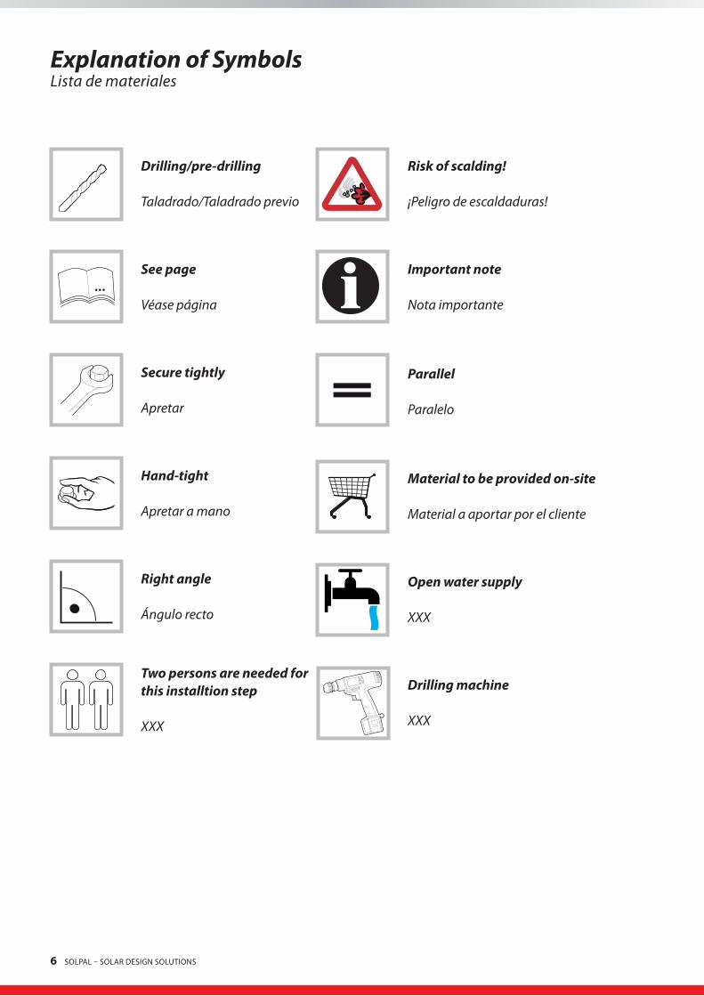
Explanation of SymbolsLista de materiales
...
Drilling/pre-drilling
Taladrado/Taladrado previo
See page
Véase página
Secure tightly
Apretar
Hand-tight
Apretar a mano
Right angle
Ángulo recto
Two persons are needed for this installtion step
XXX
Drilling machine
XXX
Risk of scalding!
¡Peligro de escaldaduras!
Important note
Nota importante
Parallel
Paralelo
Material to be provided on-site
Material a aportar por el cliente
Open water supply
XXX

SOLPAL – SOLAR DESIGN SOLUTIONS 7
Solpal L
Grossarea
Superficie bruta26 ft2
Net area
Superficie neta23 ft2
Max.height,mount45°/30°
Altura máx., soporte de 45 °/ 30°36/28 in
Collectorouterdimensions
Dimensiones exteriores del captador86 x 43 in
Volumehotwaterstoragetank
Volumen del acumulador de agua caliente sanitaria51 gal
Collector/inclineangle
Captador / Ángulo de inclinación10°-75°
Weight(withmount,nowater)
Peso (con soporte, sin agua)165 lbs
Max.workingpressure*
Sobrepresión máx. de servicio
60psi
4 bar
Weight(withmount,withwater)
Peso (con soporte, con agua)595 lbs
Cold/hotwaterconnections
Conexiones de agua fría/agua caliente sanitaria
3/4”malethread
3/4 RE
Thermalinsulation-storagetank
Aislamiento del acumuladorPUR
(1,2in)
Storagetankmaterial
Material del acumulador
stainlesssteel1.4521
Inoxidable 1.4521
Recommendedloadrangeforwatertemperatureof113°F
Rango de carga recomendado a 113 °F de temperatura del agua
37 gal/day
Heattransfermedium
Fluido portador térmico
Water
Agua
TechnicalDataDatos técnicos
Measurements(ininch)Dimensiones (en inch)
Mountonthelongside./Colóquese horizontal sobre el lado longitudinal
43
86
39
8
43
28 30°
8
43
36
36
45°
Dimensions in INCH
*Max. system pressure under test conditions: 150 psi
TOAVOIDSERIOUSBODILYHARMAND/ORPROPERTY
DAMAGE,ASSURETHATTHEWORKINGPRESSUREOFTHE
SOLPALSYSTEMDOESNOTEXCEED60PSIATANYTIME.

8 SOLPAL – SOLAR DESIGN SOLUTIONS
Solpal M
Grossarea
Superficie bruta19 ft2
Net area
Superficie neta17 ft2
Max.height,mount45°/30°
Altura máx., soporte de 45 °/ 30°27.5/22.5 in
Collectorouterdimensions
Dimensiones exteriores del captador86 x 32 in
Volumehotwaterstoragetank
Volumen del acumulador de agua caliente sanitaria38 gal
Collector/inclineangle
Captador / Ángulo de inclinación10°-75°
Weight(withmount,nowater)
Peso (con soporte, sin agua)132 lbs
Max.workingpressure*
Sobrepresión máx. de servicio
60psi
4 bar
Weight(withmount,withwater)
Peso (con soporte, con agua)452 lbs
Cold/hotwaterconnections
Conexiones de agua fría/agua caliente sanitaria
3/4”malethread
3/4 RE
Thermalinsulation-storagetank
Aislamiento del acumuladorPUR
(1,2in)
Storagetankmaterial
Material del acumulador
stainlesssteel1.4521
Inoxidable 1.4521
Recommendedloadrangeforwatertemperatureof113°F
Rango de carga recomendado a 113 °F de temperatura del agua
24 gal/day
Heattransfermedium
Fluido portador térmico
Water
Agua
TechnicalDataDatos técnicos
Measurements(ininch)Dimensiones (en inch)
Mountonthelongside. Colóquese horizontal sobre el lado longitudinal.
32
32
86
8
8
22
29
30°
32
28
28
45°
Dimension in INCH
*Max. system pressure under test conditions: 150 psi
TOAVOIDSERIOUSBODILYHARMAND/ORPROPERTY
DAMAGE,ASSURETHATTHEWORKINGPRESSUREOFTHE
SOLPALSYSTEMDOESNOTEXCEED60PSIATANYTIME.
SOLPAL – SOLAR DESIGN SOLUTIONS 9
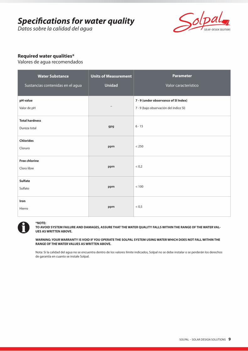
Specifications for water qualityDatos sobre la calidad del agua
Requiredwaterqualities*Valores de agua recomendados
WaterSubstance
Sustancias contenidas en el agua
UnitsofMeasurement
Unidad
Parameter
Valor característico
pHvalue
Valor de pH –
7-9(underobservanceofSlIndex)
7 - 9 (bajo observación del índice Sl)
Totalhardness
Dureza total gpg 6 - 15
Chlorides
Cloruro ppm < 250
Freechlorine
Cloro libre ppm < 0,2
Sulfate
Sulfato ppm < 100
Iron
Hierro ppm < 0,5
*NOTE:TOAVOIDSYSTEMFAILUREANDDAMAGES,ASSURETHATTHEWATERQUALITYFALLSWITHINTHERANGEOFTHEWATERVAL-UESASWRITTENABOVE.
WARNING:YOURWARRANTYISVOIDIFYOUOPERATETHESOLPALSYSTEMUSINGWATERWHICHDOESNOTFALLWITHINTHERANGEOFTHEWATERVALUESASWRITTENABOVE.
Nota: Si la calidad del agua no se encuentra dentro de los valores límite indicados, Solpal no se debe instalar o se perderán los derechos de garantía en cuanto se instale Solpal.

10 SOLPAL – SOLAR DESIGN SOLUTIONS
Hydraulic ConnectionEsquema hidráulico
1*
Collectorlooppiping:(material: copper, operating temperature 220°F or higher; diameter: not less than 3/4” )Collectorlooppipeinsulation:the cold and hot lines shall be insulated with a flexible closed cell insulation with a minimum wall thickness of 1 inch.Colectordetuberíacircular:(material: cobre o plástico, que opera TEMPERATURA 220° F o más alta; diámetro no inferior a 3/4 “)Circuitodelcolectoraislamientodetuberías:las líneas frías y calientes deben estar aislados con un aislamiento de células flexibles cerrado con un espesor mínimo de 1 pulgada.
2Combinednon-return/safteyvalve
Válvula de seguridad 6*
Servicewatermixer(presettomax140°F)(Exposed components are maintained below 140 °F or insulated/isolated)
Mezclador de agua caliente (preajustado a máx. 140 °F)(Los componentes expuestos a traffice pública se mantienen por debajo de 140 ° F o aislado / aislados)
3VentilationValve
Soupape de ventilation 7*Pressurereducungvalve
Válvula de sobrepresión
4*
Shut-offvalve
Grifo de vaciado 8Flatsealingconnection
Conexión con junta plana
5*
Draintap
Grifo de vaciado
Pleasenotethatathreadadapter(seepage5,part6.4)hastobeusedforAmericanNPTthreadsincombinationwithSolpalconnectionsandvalves.
* Materialtobeprovidedon-site Material a aportar por el cliente
WARNING:TOAVOIDSERIOUSBODILYINJURYORDAMAGE,ALLCOMPONENTSSHOWNINTHEDRAWINGABOVEMUSTBEINSTALLED.Es necesario montar los componentes representados en el esquema.
max. 60 psi
Stand alone (Pleasenote:thissystemisnotSRCCcertified SRCC requires a backup heating , shown at pages 12 to 14)
1
9bar
01
2 8
9
5
10
34 6
7
4
5
5
2
64
5
8
3 8
bar0
1
2 8
9
5
10
34 6
7
max. 4 bar
7
3
8
5
28

SOLPAL – SOLAR DESIGN SOLUTIONS 11
2
SAFETY VALVE This valve is a pressure release mechanisms used in pressure systems. It has a non-return valve integrated. The use of these valves is strictly required due to safety regulations. The safety valve opens at a pressure of 90 psi to reduce excess pressure.
Recommended safety valve with non-return for water heater: ¾”, opening at 90 PSI pressure UV- resistant, Material: hot molded BRASS UNI EN 12165CW617N, nickel plated surface max. working temperature: 250°F
3
VENTILATION VALVE
This valve ensures that no vacuum is created when draining the water tank. In the event of negative pressure, the ventilation valve automatically supplies the system with air.
Recommended ventilation valve: ¾”, with DN15 solar neoperl backflow preventer, UV-resistant Material: brass max. working temperature: 250°F
4
COLD WATER SUPPLY ISOLATION VALVE
This valve should stay open to allow water from the public water system to fill the Solpal water tank. When this valve is closed, the Solpal and the supplemental water heater are disconnected from the pressurized mains of the public water system.
Recommended ball valve:
¾” fully ported Brass Ball Valve for heating, plumbing, and industrial applications max. safe operating pressure 600 psi temperature Range up to 250° F
4
HOT WATER SUPPLY ISOLATION VALVE
Keep this valve open to assure that hot water can drain or escape in case of overheating. This valve can temporarily be closed for maintenance purposes.
Recommended ball valve:
¾” fully ported Brass Ball Valve for heating, plumbing, and industrial applications max. safe operating pressure 600 psi temperature range up to 250° F
5
DRAIN VALVE This boiler drains are normally closed and capped. Use these valves to drain the Solpal. Attach a garden hose to both drain valves. Terminate the hoses in either a service basin or an appropriate spot outside the house. Open both boiler drains at once to drain the unit. WARNING: WATER MAY BE DISCHARGED AT VERY HIGH TEMPARATURES. TO AVOID SCALDING, EXERCISE MAXIMUM CAUTION WHEN DRAINING THE HOT WATER FROM THE SOLPAL. DO NOT POINT HOSE AT PERSONS OR PETS. ALWAYS DISCHARGE THE HOT WATER TO A SAFE PLACE.
Recommended drain valve:
¾” unibody ball valve max. temperature: 250°F Standard Port Opening with hose union and cap delivered separately
6
THERMOSTATIC MIXING VALVE This valve controls the temperature of the warm water output. According to local standards the valve must have a scald safe function. Scald safe means that in the case of a cold water failure, the hot water supply shuts off automatically.
Recommended mixing valve: ESBE VTA 322, 95 - 140°F, G 1”, PN10 _____________________________ External thread, ISO 228/1
7
PRESSURE REDUCING VALVE
This valve should ensure a constant output pressure of 60 psi independent of the input pressure delivered from any source.
Recommended pressure reducing valve: Honeywell D06F-1A, G 1”, brass, dezincification resistant Pressure setpoint range: 20 to 90 psi
8
3 WAY BALL VALVE This valve provides solar system cold water shut off without interrupting normal cold water service.
Recommended 3-way ball valve:
Honeywell ¾” 3-way globe mixing valve, V5013N max. pressure: 240 psi Material: Brass temperature Range: up to 250°F threaded (IPS)
9
Thermometer To determine whether the solar system is working, it is necessary to install a thermometer.
Recommended thermometer:
Temperature Range: 32 °F to 250 °F
Overview of componentstítulo de los componentes

12 SOLPAL – SOLAR DESIGN SOLUTIONS
Hydraulic ConnectionEsquema hidráulico
Pre-heater tankless gas
AuxilliaryWaterHeatingEquipment Auxilliary water heater must have adequate capacity, listed and labeled by an accredited listing organization
3
2
5B4
6
8
7 5A
4
9b9a
cold water inlet
hot water outlet
SOLPAL – SOLAR DESIGN SOLUTIONS 13
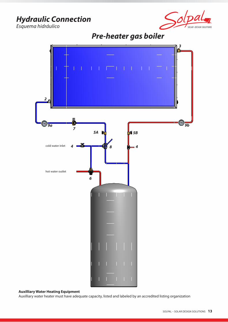
Pre-heater gas boiler
Hydraulic ConnectionEsquema hidráulico
3
2
5B
48
75A
6
4
9b9a
cold water inlet
hot water outlet
AuxilliaryWaterHeatingEquipment Auxilliary water heater must have adequate capacity, listed and labeled by an accredited listing organization
14 SOLPAL – SOLAR DESIGN SOLUTIONS
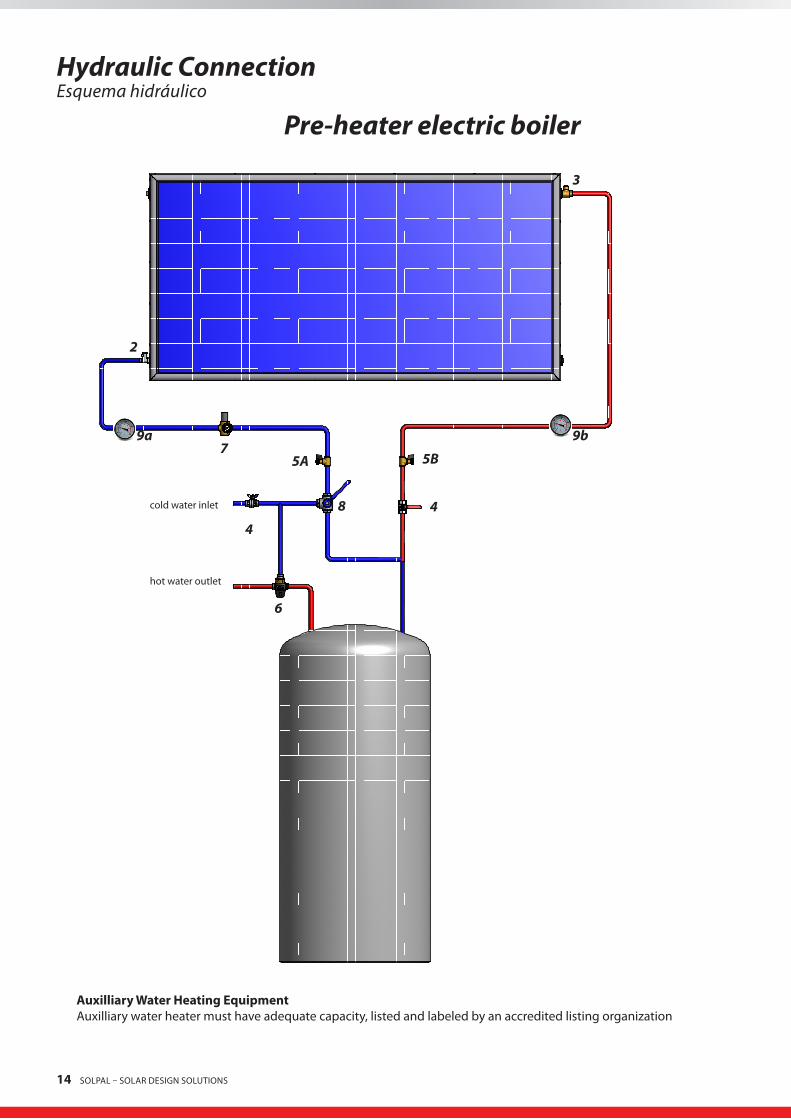
Hydraulic ConnectionEsquema hidráulico
Pre-heater electric boiler
3
2
5B
48
75A
6
4
9b9a
cold water inlet
hot water outlet
AuxilliaryWaterHeatingEquipment Auxilliary water heater must have adequate capacity, listed and labeled by an accredited listing organization
SOLPAL – SOLAR DESIGN SOLUTIONS 15
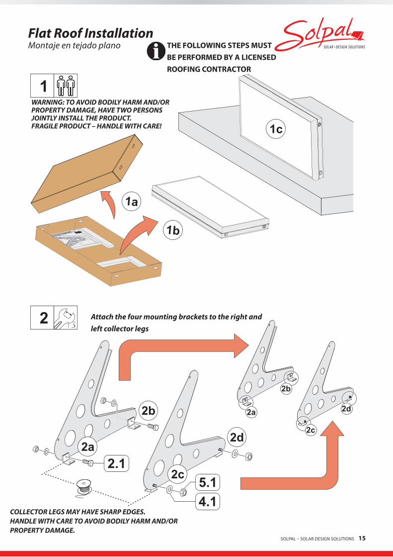
Flat Roof InstallationMontaje en tejado plano
2b
2d2a
2c
2 13
2d2a
2b
2c
1
2.1
4.15.1
1a
1b
1c
17DE GB
FlachdachmontageFlat roof mounting
2b
2d2a
2c
2 13
2d2a
2b
2c
1
2.1
4.15.1
1a
1b
1c
17DE GB
FlachdachmontageFlat roof mounting
WARNING: TO AVOID BODILY HARM AND/OR PROPERTY DAMAGE, HAVE TWO PERSONS JOINTLY INSTALL THE PRODUCT. FRAGILE PRODUCT – HANDLE WITH CARE!
Attach the four mounting brackets to the right and left collector legs
COLLECTOR LEGS MAY HAVE SHARP EDGES. HANDLE WITH CARE TO AVOID BODILY HARM AND/OR PROPERTY DAMAGE.
THEFOLLOWINGSTEPSMUSTBEPERFORMEDBYALICENSEDROOFINGCONTRACTOR
16 SOLPAL – SOLAR DESIGN SOLUTIONS
DEGB
SichernEnsure
3
425 Nm
3.12.2
2.2
3.1
4.1
4b
4a
4c4d
90°
4a-4d
18 DE GB
FlachdachmontageFlat roof mounting
DEGB
SichernEnsure
3
418 ft lb
3.12.2
2.2
3.1
4.1
4b
4a
4c4d
90°
4a-4d
18 DE GB
FlachdachmontageFlat roof mounting
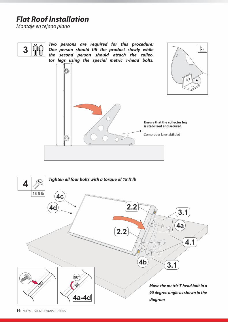
Ensurethatthecollectorlegisstabilizedandsecured. Comprobar la estabilidad
Two persons are required for this procedure: One person should tilt the product slowly while the second person should attach the collec-tor legs using the special metric T-head bolts.
Tighten all four bolts with a torque of 18 ft lb
Flat Roof InstallationMontaje en tejado plano
Move the metric T-head bolt in a
90 degree angle as shown in the
diagram
SOLPAL – SOLAR DESIGN SOLUTIONS 17
Flat Roof InstallationMontaje en tejado plano
5
6 6a-6d
6b
6c6d
6a
19DE GB
FlachdachmontageFlat roof mounting
5
6 6a-6d
6b
6c6d
6a
19DE GB
FlachdachmontageFlat roof mounting
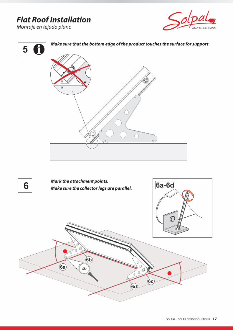
Make sure that the bottom edge of the product touches the surface for support
Mark the attachment points.Make sure the collector legs are parallel.

18 SOLPAL – SOLAR DESIGN SOLUTIONS
7
8
7a
8a/8b
Ø14
8a8b
20 DE GB
FlachdachmontageFlat roof mounting
7
8
7a
8a/8b
Ø9/16
8a8b
20 DE GB
FlachdachmontageFlat roof mounting
Carefully move product. Drill holes. Put product back and attach to roof surface.
Flat Roof InstallationMontaje en tejado plano
SOLPAL – SOLAR DESIGN SOLUTIONS 19
9
9b
9a
18 ft lb9b
1/2x3 in
10 11
12 13
21DE GB
FlachdachmontageFlat roof mounting
Flat Roof InstallationMontaje en tejado plano
10 11
12 13
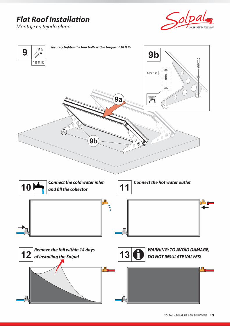
Securely tighten the four bolts with a torque of 18 ft lb
Connect the cold water inletand fill the collector
Connect the hot water outlet
Remove the foil within 14 daysof installing the Solpal
WARNING: TO AVOID DAMAGE,DO NOT INSULATE VALVES!

20 SOLPAL – SOLAR DESIGN SOLUTIONS
2-10 in2-10 in
1
1.3
2.3
2
On-Roof InstallationMontaje sobre tejado
THEFOLLOWINGSTEPSMUSTBEPERFORMEDBYALICENSEDROOFINGCONTRACTOR
Affix the bottom collector straps (1.3) to the beams under the roof-ing materials

SOLPAL – SOLAR DESIGN SOLUTIONS 21
On-Roof InstallationMontaje sobre tejado
90°
2.2
4.1
5.1
3
2.3
1.4
4
Move the metric T-head bolt in a
90 degree angle as shown in the
diagram
Affix the bottom collector straps (1.4) to the beams under the roof-ing materials
WARNING: TO AVOID BODILY HARM AND/OR PROPERTY DAMAGE, HAVE TWO PERSONS JOINTLY PERFORM THE FOLLOWING INSTALLATION STEPS. FRAGILE PRODUCT – HANDLE WITH CARE!
22 SOLPAL – SOLAR DESIGN SOLUTIONS
2.24.15.1
90°
5
6 7
8 9
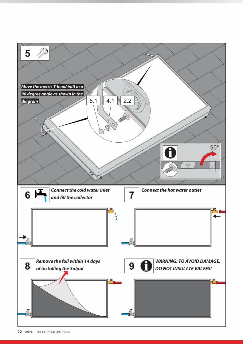
Move the metric T-head bolt in a
90 degree angle as shown in the
diagram
Connect the cold water inletand fill the collector
Remove the foil within 14 daysof installing the Solpal
Connect the hot water outlet
WARNING: TO AVOID DAMAGE,DO NOT INSULATE VALVES!

SOLPAL – SOLAR DESIGN SOLUTIONS 23
Installation Instructions
GeneralInstallationandTransportInstructions
Installation, maintenance, cleaning and all other procedures listed in this manual shall only be performed by fully and properly instructed, qualified and authorized personnel, which means licensed installers, contractors, plumbers, HVAC and solar contractors. The materials sup-plied must be used for installation. Before any installation or operation of the Solpal system you have to familiarize yourself with and then comply with all national, state and local laws and regulations that apply.Lift the Solpal system only by its frame and NEVER by any of the water connections or bolts. Incorrect lifting can damage the Solpal system. Always be careful to avoid any physical damage, especially to the solar glass, back wall and pipe connections. The manufacturer is not li-able for structural damage or any other damage caused by improper handling or incorrect installation. Flatroofinstallation
Installation shall only be carried out on roof surfaces or substructures with sufficient load bearing capacity. The structural load bearing ca-pacity of the roof or substructure must be inspected, tested and approved in accordance with local and regional conditions by a structural engineer before the Solpal system can be installed. During inspection the structural engineer must pay particular attention to the quality of the substructure for proper anchoring of the retaining screw connections used to secure the installation materials for the Solpal system. Inspection of the entire installation structure in accordance national and local regulations is particularly necessary in areas with heavy snowfall that can lead to increased load. When choosing the installation location, make sure that maximum loads are not exceeded by snowfall or wind forces.
There must be at a distance of at least 3 ft to the roof ridging or edge.
Note: Installing a Solpal system means changing the structure of an (existing) roof. Extended and inhabited lofts or inadequate minimum roof inclinations often require additional measures carried out on-site by a licensed roofing contractor e.g. sarking, to secure against water penetrating as a result of wind pressure and drifting snow. For larger systems, it is recommended to secure sarking on a separately mounted construction of steel bars. Using concrete ballast blocks and cable bracing as a means of securing system components protects the roof membrane from being perforated during installation. Rubber mats should be used if necessary to increase the friction between the roof and concrete ballast blocks and avoid damage to the roof membrane. For additional security against peak wind loads, steel cables of a suitable thickness (typically 0.2 in) are required.
Onroofinstallation
Installation shall only be carried out on roof surfaces or substructures with sufficient load bearing capacity. The structural load bearing capacity of the roof or substructure must be tested in terms of local and regional conditions by a structural engineer before installing the Solpal system. During inspection pay particular attention to the quality of the substructure for retaining screw connections used to secure the installation materials for the Solpal system. Inspection of the entire installation structure in accordance national and local regulations is particularly necessary in areas with heavy snowfall that can lead to increased load. When choosing the installation location, make sure that maximum loads are not exceeded by snowfall or wind forces.
The inspection should also take into account any particularities of the installation location, e.g. air jets, eddies etc. that can lead to in-creased load. When choosing the installation location, make sure that maximum loads are not exceeded due to snowfall or wind forces. There must be a distance of at least 3 ft to the roof ridging or edge. Structural members penetrated by solar system components must meet code. Building materials adjacent to solar components must not be not exposed to elevated temperatures.
Penetration through fire-rated assemblies do not reduce fire resistance below code.Meet applicable codes and national Roofing Contractors Assoc. practices.Do not impair enclosure function.Do not allow vermin intrusion.
EN
ES

24 SOLPAL – SOLAR DESIGN SOLUTIONS
EN
ES Connectionsandpiping
The Solpal system shall be connected to the connection piping with a 3⁄4” external thread screw, flat-sealing. Before tightening the con-nection, check to make sure that seals are positioned properly. Use a torque wrench to tighten the connection and do not exceed a torque of 30 ft. lbs. It is best to use flexible connection elements to allow for heat expansion and contraction due to fluctuating temperatures. In the alternative, the use of suitable expansion bends and flexible piping is a way to compensate for the heat expansion and contraction due to temperature fluctuations. Only use pipes suited for use in sanitary facilities and which can withstand temperatures of at least 212 °F. The Solpal system requires the use of all copper or brass fittings in the collector loop plumbing. Couplings rather than unions should be used to join the collectors to avoid leaks and fluid loss. Use only lead-free solder. Note:the piping supports must not compress the insulation. If this is not possible, insulate the piping supports as well.Topreventdielectriccorrosion,makesurethatthereisnoconnectionbetweenstainlessorgalvanizedsteelpipesandcopperpipes.
CollectorLoopPipeInsulationThe collector loop cold water supply and hot return lines shall be well insulated with high quality flexible closed cell insulation to mi-nimize heat loss. Use closed-cell tube insulation with a wall thickness of ¾” such as Armafelx, Rubatex or Insul-tube in mild climates. In cold climates, where freezing occurs, use insulation with 1 1/2“ wall thickness. Any above ground exterior pipe insulation is subject to UV degradation and must be jacketed, wrapped with aluminum foil tape, or painted with two coats of high quality water-based acrylic resin coating as supplied by the insulation manufacturer. To the extent possible, slide the insulation material over the pipe without cutting or taping. Seal all butt joints with contact adhesive. Do not use rigid polyethylene pipe insulation. Insulate the cold and hot water lines with flexible closed-cell tube insulation with a wall thickness of 1”. Insulate the pipes with a suitable material of appropriate thickness in order to reduce heat loss and protect the pipes from freezing. Do not insulate the valves (see page 5, part 6.2 and 6.3).
InclinationoftheSolpalsystem/GeneralUse the Solpal system only if it can be installed so that it has an inclination of at least 10° but no more than 75°. Protect the system connec-tions from contaminants entering the system, like dust etc.
Warranty
The manufacturer provides a limited warranty for 10 years. Please refer to the enclsoed Kioto Clear Energy AG Liability Policy for details (see chapter appendix).
The solar energy system described by this manual, when properly installed and maintained, meets the minimum standards established by the SRCC. This certification does not imply endorsement or warranty of this product by SRCC.
Howtoobtainwarranty
Pursuant to this Limited Warranty, Heliodyne, Inc. will, at its option, (i) repair the product using new or refurbished parts, or (ii) replace the product with a new or refurbished product. For purposes of this Limited Warranty, “refurbished” means a product or part that has been re-turned to its original specifications. In the event of a defect, these are your exclusive remedies. In case Heliodyne, Inc. replaces the product, the shape and color may vary slightly from the original unit.
To obtain warranty service, you must notify Heliodyne, Inc. within 90 days of discovery of the defect, and deliver the product, freight pre-paid, in either its original packaging or packaging affording an equal degree of protection to the Heliodyne, Inc. authorized service facility specified. A dated purchase receipt or bill of sale and a detailed error description are required. For specific instructions on how to obtain warranty service for your product, visit Heliodyne, Inc. Web Site: www.heliodyne.com or call the Heliodyne, Inc. Information Service Center, toll free number: 1.888.878.8750 This Limited Warranty shall apply to any repair, replacement part or replacement product for the remainder of the original Limited Warran-ty period. Any parts or product replaced under this Limited Warranty will become the property of Heliodyne. Inc..
This Limited Warranty does not cover Heliodyne, Inc. products sold AS IS or WITH ALL FAULTS or consumables or wearing parts (such as fuses or batteries). This Limited Warranty is invalid if the factory-applied serial number has been altered or removed from the product.
SOLPAL – SOLAR DESIGN SOLUTIONS 25
Operating Instructions
General
The Solpal system only offers unlimited performance when installed in frost-free zones. Ifthetemperaturefallsbelow20°Ffor18con-secutivehoursor10°Ffor6consecutivehours,theSolpalsystemmustbedrainedandcovered. The Limited Warranty is void, if you do not drain and cover the Solpal under the temperature conditions described above. Appropriate insulation or pipe heat tracing must be provided on-site to prevent hot and cold water pipes from freezing. A thermal mixer, at which the required water temperature can be set, must always be installed at the hot water outlet.
The safety valve provided must be installed at the cold water connection of the Solpal system to limit positive pressure in the water circuit. The freeze tolerance limits are based upon an assumed set of environmental conditions. Extended periods of cold weather, including ambient air temperatures below the specified limit, may cause freezing in exposed parts of the system. It is the owner’s responsibility to protect the Solpal system in accordance with the manufacturer’s instructions if the air temperature is anticipated to approach the specified freeze tolerance limits.
OperatingandFillingInstructions
The Solpal system is delivered with a protective film on the solar glass. Do not remove this film, which blocks the sunlight, until after the system has been filled with water. Otherwise the system components can be damaged because the unblocked sunlight heats up the emp-ty system which lacks water to absorb the heat. Remove the protective film after the system has been filled, as it serves no other purpose. It is recommended that you fill the system within 2 weeks after installation, as otherwise residue from the film may adhere to the solar glass. Repeat filling and flushing until you are sure that all air has been removed from the system. Make sure that the maximum operating pressure stated on the type plate or in the installation instructions is not exceeded. Check to make sure that all safety components have been installed in accordance with the hydraulic diagram (in the chapter “Hydraulic Connection” in this manual) before you open the water supply and fill the system before initial start-up.
1. If possible, fill the collector in the morning before sun light heats up the absorber. 2. It is recommended that you fill the collector before you connect the return piping to the collector outlet, or open the pressure relief
valve or open the boiler drain on the return line, or that you make in some other fashion sure that the system is vented to the atmos-phere. Failure to follow these instructions could void the warranty and damage the system.
3. Set the flow control valves to the solar pre-heat position. Consult system valve position drawings. Close the boiler drain on the supply side to the solar loop piping. Open the boiler drain on the return side.
4. It is most important that the unit be vented to the atmosphere before and while being filled. It is recommended that the collector be filled before connecting the return piping to the collector outlet, or open the pressure relief valve or open the boiler drain on the return line, or in some other fashion make sure the unit is vented to the atmosphere. Failure to follow these instructions could void the warranty and damage the unit.
5. Open the cold water shut-off valve to fill the collector. Allow the air to be purged from the system through the open boiler drain on the return side of the solar loop piping.
6. Allow water to flow from the system for several minutes to flush out the collector and the piping.7. Close the open boiler drain.Carefullyinspectthesystemforleaks.Open the 2-way ball valve (#4 in the plumbing drawings).8. Turn on a hot water faucet in the house to purge any remaining air from the system.9. Make sure all FSEC, SRCC and manufacturer required labels are placed on the system. Consult FSEC or SRCC appendix for required
labels and their placements.10. For installation and operation of the instantaneous water heater, please follow the manufacturer operation manual
InstructionsonMaintenance/DrainingtheSystem
Conduct an inspection of the Solpal system at least annually for any damage, leakage and soiling. The manufacturer recommends annual maintenance by a qualified specialist (licensed installer, contractor, plumber, HVAC and solar contractor). For maintenance or repair work on the Solpal system that requires the water content to be drained off, the entire system must be covered by a light-reflective cloth or foil to prevent damage by possible over heating. A original cover is available at your Solpal partner.

26 SOLPAL – SOLAR DESIGN SOLUTIONS
EN
ES
Please have a look at the diagramm shown on page 10.
1. Close cold and hot water supply page 10 (No. 4)2. Attach hoses to both boiler drains and terminate the hoses in either a service basin or an appropriate spot outside the house.3. Open both boiler drains at the same time to drain the Solpal system (No. 5),
WARNING:WATERMAYBEDISCHARGEDATVERYHIGHTEMPERATURESOFUPTOOREXCEEDING212DEGREES FAHRENHEIT.TOAVOIDSCALDING,EXERCISEMAXIMUMCAUTIONWHENDRAININGTHEHOTWATERFROMTHE SOLPAL.DONOTPOINTHOSEATPERSONSORPETS.ALWAYSDISCHARGETHEHOTWATERTOASAFEPLACE.4. After all water has been drained from the collector, close both boiler drains (No. 5) and remove hoses
The conventional water heater will continue to provide hot water to the household when the Solpal system is by-passed and drained.
OperatingIf the homeowner cannot get water to flow from the hot water lines, the problem is probably with the local water source and not the sys-tem. Check the cold water supply. To determine whether the Solpal system is working, observe the thermometer when hot water is being used in the house. The water returning from the Solpal on a sunny day (No. 9b on page 12) should be at least 15 K warmer than the water going up to the Solpal (No. 9a on page 12).
CAUTIONDon’ttouchthehotpipes!
IncreasingEfficiency
To increase the efficiency of the Solpal system: – If possible, use hot water in the evening. For example take showers in the evening rather than during the day. – The performance of Solpal system in the Northern Hemisphere is optimized when the Solpal is mounted facing true south. Performance, however, suffers very little when the Solpal is oriented no more than 45° East or 45° West of True South. –The collector should be in unobstructed direct sunlight between 9:00 a.m. and 3:00 p.m. on any day of the year.
SystemoperatingPressure
The maximum operating pressure in the water circuit must be limited to 60 psi at all times. Install a pressure reducer if necessary.
Leavingthesystemunused
If the Solpal system is to be unused for a long period of time, such as absence due to vacation, it is best to leave the Solpal system filled with water and in the solar pre-heat mode. If unused for long periods of time during winter months in freezing climates, it is best to drain the collector and the solar loop piping. The entire system must be covered by a light-reflective cloth or foil to prevent damage due to over heating. A original cover is available at your Solpal partner.
CAUTION

SOLPAL – SOLAR DESIGN SOLUTIONS 27
Indicaciones para el montaje
Indicacionesgeneralesydetransporte
El montaje, mantenimiento y limpieza sólo deben ser realizados por empresas especializadas. Todas las indicaciones de estas instrucciones van dirigidas exclusivamente a tales empresas especializadas. De forma general, el montaje se debe realizar con el material suministra-do. Infórmese antes del montaje y uso del Solpal sobre las normas y directivas locales vigentes al respecto. El sistema de agua caliente sanitaria no se debe levantar tomándolo por las conexiones ni por las uniones de rosca. Evite los golpes y los efectos mecánicos en el sistema de agua caliente sanitaria, especialmente en el vidrio solar, en la pared posterior y en las conexiones de los tubos.Si el montaje no se realiza correctamente, el fabricante no se responsabilizará por deterioros en la obra, en los aparatos, etc.
Estática-Tejadoplano
El montaje se debe realizar sólo sobre superficies de tejado o subestructuras con suficiente capacidad de carga. Siempre con la ayuda de un especialista en cálculos estáticos, el cliente debe comprobar la capacidad de carga del tejado o de la subestructura en cuanto a las circunstancias locales y regionales, antes de montar el Solpal. Al hacerlo, se debe prestar especial atención a la ca-lidad de la subestructura en lo relativo a la durabilidad de las uniones atornilladas para la fijación de dispositi-vos de montaje del Solpal. La comprobación de la estructura total conforme según las disposiciones vigentes espe-cíficas de cada país es especialmente necesaria en zonas de mucha nieve o en zonas con altas velocidades del viento. Se deben tener también en cuenta las características específicas del lugar de instalación (viento seco, chorros de aire, formación de remolinos, etc.) que pueden dar lugar a una carga mayor. A la hora de elegir el lugar de montaje, se debe tener en cuenta que las cargas máximas no se deben superar ni por la fuerza de la nieve, ni por la del viento. La distancia a las cumbreras/bordes del tejado debe ser de 3 ft como mínimo.
Nota: El montaje de Solpal supone la intervención en un tejado (existente), especialmente en el caso de áticos acondicionados y habitados o cuando no se alcanzan las pendientes mínimas del tejado, el cliente deberá tomar medidas adicionales (p. ej., membranas protectoras bajo la cubrición del tejado) para asegurar la cubrición contra la penetración de agua provocada por la presión del viento y la nieve volátil. Para la instalaciones de mayor tamaño se recomienda el montaje sobre una construcción portadora propia de perfiles de acero. La variante de fijación con bloques de lastre de hormigón y arriostramiento de cable posibilita el montaje sin necesidad de perfo-rar la cubierta del tejado. A fin de aumentar la fricción estática entre el tejado y los bloques de lastre de hormigón, así como para evitar deterioros en la cubierta del tejado, se deben utilizar, de ser necesario, mantas de asiento de goma. Para la absorción de cargas producidas por ráfagas de viento es necesaria una fijación adicional con cables de acero del grosor correspondiente (media de 0,2 in).
Estática-Tejadosinclinados
El montaje se debe realizar sólo sobre superficies de tejado o subestructuras con suficiente capacidad de carga. Siempre con la ayuda de un especialista en cálculos estáticos, el cliente debe comprobar la capacidad de carga del tejado o de la subestructura en cuanto a las circunstancias locales y regionales, antes de montar el Solpal. Al hacerlo, se debe prestar especial atención a la calidad de la subestructura en lo relativo a la durabilidad de las uniones atornilladas para la fijación de dispositivos de montaje del Solpal. La comprobación de la estructura total del sistema conforme según las disposiciones vigentes específicas de cada país es especialmente necesaria en zonas de mucha nieve o en zonas con altas velocidades del viento. Se deben tener también en cuenta las características específicas del lugar de ins-talación (viento seco, chorros de aire, formación de remolinos, etc.) que pueden dar lugar a una carga mayor. A la hora de elegir el lugar de montaje, se debe tener en cuenta que las cargas máximas no se deben superar ni por la fuerza de la nieve, ni por la del viento. La distancia a las cumbreras/bordes del tejado debe ser de 3 ft como mínimo.
EN
ES

28 SOLPAL – SOLAR DESIGN SOLUTIONS
EN
ES
Conexiones
Solpal está equipado con una unión roscada de 3⁄4" RE y se debe unir a la tubería de conexión mediante junta plana. Antes de apretar, compruebe la correcta colocación de las juntas, utilice una llave dinamométrica y no sobrepase el par de 30 lb/ft. En el caso de que no se hayan previsto mangueras flexibles como elementos de unión, al conectar las tuberías se deben tomar medidas para compensar la dilatación por calor causada por las fluctuaciones de temperatura (p. ej., arcos de dilatación, tuberías flexibles). Utilice tubos adecuados para el ámbito sanitario y que resistan temperaturas de 212 °F como mínimo. Aísle los tubos con un material adecuado de suficiente grosor para reducir las pérdidas por calor y para protegerlos contra las heladas.
Inclinación del Solpal / Generalidades Solpal es adecuado para pendientes entre 10 ° y 75 °. Las conexiones del sistema se deben proteger contra la suciedad, como la entrada de polvo, etc.
Garantía
La garantía se extiende a 5 años siempre que se pueda demostrar que los trabajos de mantenimiento han sido correctamente realizados por una empresa especializada. Para poder disfrutar de los derechos de la garantía, es condición también que el montaje lo haya realizado una empresa especializada siguiendo estrictamente las instrucciones. El plazo de garantía comienza con la entrega al socio contractual o con la aceptación por parte del mismo. La calidad del agua varía notablemente de una región a otra, por lo que en algunos casos la corrosión o la cal pueden suponer un problema. El fabricante no puede aceptar reclamaciones de garantía por la corrosión ocasionada por el agua. Debemos subrayar aquí que el establecimiento de una determinada calidad del agua no constituye ninguna garantía contra la corrosión - se debe ver como un auxiliar para evitar aplicaciones críticas del agua. En el capítulo "Información sobre la calidad del agua" de este manual encontrará una sinopsis de los parámetros críticos del agua y de sus valores límite recomendados.

SOLPAL – SOLAR DESIGN SOLUTIONS 29
Notas sobre el funcionamiento
Generalidades
El Solpal se puede utilizar sin restricciones sólo en zonas libres de heladas. Si las temperaturas bajan Si la temperatura cae por debajo de 20 ° F durante 18 horas consecutivas o 10 ° F durante 6 horas consecutivas, el sistema Solpal debe ser drenado y cubierto. A la salida de agua caliente se debe postconectar siempre un mezclador térmico en el que se pueda ajustar la temperatura deseada del agua caliente. Para limitar la sobrepresión en el circuito de agua, se debe montar la válvula de seguridad suministrada en la conexión de agua fría del Solpal.
Notassobrelapuestaenservicioyelllenado
Solpal se suministra con una lámina protectora en el vidrio. Ésta se debe retirar sólo después de haber llenado la instalación para evitar un deterioro de los componentes en estado vacío por la posible formación de calor. Después de llenar el sistema, la lámina protectora se debe retirar ya que, de otro modo, el sistema no puede funcionar. Se recomienda llenar el sistema en las 2 semanas siguientes al montaje para evitar que en el vidrio queden restos de lámina. El llenado y el lavado se deben realizar hasta que quede garantizado que el sistema está completamente purgado de aire. No se debe superar la presión de servicio indicada en la placa de características o en las instrucciones de montaje. Antes de la puesta en servicio se debe comprobar si todos los componentes de seguridad se han instalado en conformidad con el esquema hidráulico (en el capítulo "Conexión hidráulica" de este manual) de las instrucciones de montaje antes de abrir la entrada de agua para llenar el acumulador. Se recomienda esperar 2 semanas desde el primer llenado del sistema antes de utilizar el agua como agua potable.
Notassobreelmantenimientoyelvaciadodelsistema
Solpal se debe someter anualmente a un control óptico en cuanto a diversos daños, estanqueidad y suciedad, recomendándose también un mantenimiento anual por parte de una empresa especializada. A la hora de realizar trabajos de mantenimiento o reparación en el Solpal que requieran vaciar el contenido de agua, todo el sistema se deberá cubrir con un textil o lámina que no deje pasar la luz para evitar el deterioro del sistema por la posible formación de calor.
Aumentodelaeficiencia
Para aumentar la eficiencia del Solpal, se deben observar los siguientes puntos:– Consumir el agua caliente preferentemente por la noche (p. ej., en la ducha).
Presióndeservicio
La presión de servicio máxima en el circuito de agua no debe superar los 4 bares, en caso necesario, se debe utilizar un reductor de presión.

30 SOLPAL – SOLAR DESIGN SOLUTIONS
Appendix / apéndice
Labels The following labels/tags must be attached to the relevant valves in the systems in order for it to be considered OG-300 complaint. The page should be laminated, each label cut from it, punched in the margin at the left hand side and affixed to the appropriate valve with a wire tie, plastic ties are inappropriate due to high operating temperatures and UV-radiation. Failure to affix these labels will void the SRCC OG-300 system certification.
2
SAFETY VALVE This valve is a pressure release mechanisms used in pressure systems. It has a non-return valve integrated. The use of these valves is strictly required due to safety regulations. The safety valve opens at a pressure of 90 psi to reduce excess pressure.
3
VENTILATION VALVE This valve ensures that no vacuum is created when draining the water tank. In the event of negative pressure, the ventilation valve automatically supplies the system with air.
4
COLD WATER SUPPLY ISOLATION VALVE This valve should stay open to allow water from the public water system to fill the Solpal water tank. When this valve is closed, the Solpal and the supplemental water heater are disconnected from the pressurized mains of the public water system.
4
HOT WATER SUPPLY ISOLATION VALVE
Keep this valve open to assure that hot water can drain or escape in case of overheating. This valve can temporarily be closed for maintenance purposes.
5
DRAIN VALVE This boiler drains are normally closed and capped. Use these valves to drain the Solpal. Attach a garden hose to both drain valves. Terminate the hoses in either a service basin or an appropriate spot outside the house. Open both boiler drains at once to drain the unit. WARNING: WATER MAY BE DISCHARGED AT VERY HIGH TEMPARATURES. TO AVOID SCALDING, EXERCISE MAXIMUM CAUTION WHEN DRAINING THE HOT WATER FROM THE SOLPAL. DO NOT POINT HOSE AT PERSONS OR PETS. ALWAYS DISCHARGE THE HOT WATER TO A SAFE PLACE.

SOLPAL – SOLAR DESIGN SOLUTIONS 31
Appendix / apéndice
6
THERMOSTATIC MIXING VALVEThis valve controls the temperature of the warm water output. According to local standards the valve must have a scald safe function.
Scald safe means that in the case of a cold water failure, the hot water supply shuts off automatically.
7
PRESSURE REDUCING VALVE
This valve should ensure a constant output pressure of 60 psi independent of the input pressure delivered from any source.
8
3 WAY BALL VALVE
This valve provides solar system cold water shut off without interrupting normal cold water service.

32 SOLPAL – SOLAR DESIGN SOLUTIONS
Freeze Protection: The following labels must be attached to the relevant valves in the systems in order for it to be considered OG-300 complaint. The page should be laminated, each label cut from it, punched in the margin at the left hand side and affixed to the appropriate valve with a wire tie, plastic ties are inappropriate due to high operating temperatures and UV-radiation. Failure to affix these labels will void the SRCC OG-300 system certification.
Solpal may be installed in areas within the United States that experience mild winter climates. Because of the huge mass of water inside the Solpal, the system does not freeze. However, the
Solpal must be drained if the temperatures have ever fallen to:
10°F for 6 consecutive hours, or
20°F for 18 consecutive hours
When these environmental conditions are met or exceed the Solpal must be manually drained in accordance with the installation instruction. Failure to do so will void the warranty coverage.
Freeze Protection:
10°F for 6 consecutive hours, or
20°F for 18 consecutive hours
When these environmental conditions are met or exceed the Solpal must be manually drained in accordance with the installation instruction.
DRAIN Procedure:
VALVE 4 COLD WATER SUPPLY ISOLATION VALVE
VALVE 5 DRAIN VALVE
Valve 4 is normally open and allows cold water to fill the Solpal. When close the valve the Solpal is isolated from the pressurized city cold water supply line piping. To drain the system from the water, it is necessary to open valve 5, now the system is empty. WARNING: WATER MAY BE DISCHARGED AT VERYHIGH TEMPERATURE OF UP TO OR EXCEEDING 212 °F.
Appendix / apéndice
SOLPAL – SOLAR DESIGN SOLUTIONS 33
Appendix / apéndice
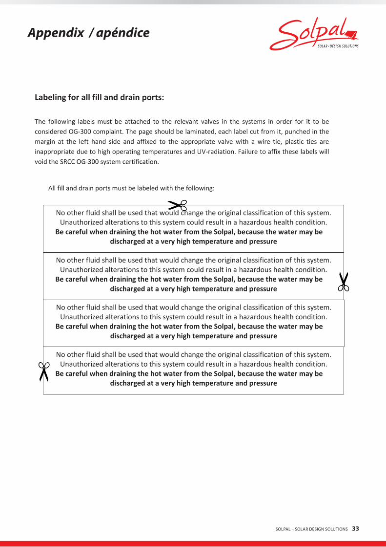
Labeling for all fill and drain ports: The following labels must be attached to the relevant valves in the systems in order for it to be considered OG-300 complaint. The page should be laminated, each label cut from it, punched in the margin at the left hand side and affixed to the appropriate valve with a wire tie, plastic ties are inappropriate due to high operating temperatures and UV-radiation. Failure to affix these labels will void the SRCC OG-300 system certification.
No other fluid shall be used that would change the original classification of this system. Unauthorized alterations to this system could result in a hazardous health condition.
Be careful when draining the hot water from the Solpal, because the water may be discharged at a very high temperature and pressure
All fill and drain ports must be labeled with the following:
No other fluid shall be used that would change the original classification of this system. Unauthorized alterations to this system could result in a hazardous health condition.
Be careful when draining the hot water from the Solpal, because the water may be discharged at a very high temperature and pressure
34 SOLPAL – SOLAR DESIGN SOLUTIONS
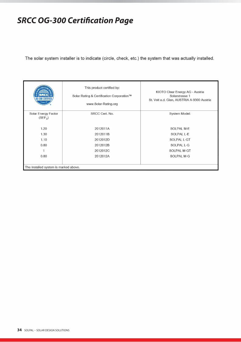
SRCC OG-300 Certification Page

SOLPAL – SOLAR DESIGN SOLUTIONS 35
KiotoClearEnergyAGLiabilityPolicy
Kioto Clear Energy AG offers a range of integrated collector-storage systems for residential and commercial use. The products are designed by Kioto Clear Energy AG and Heliodyne Corporation is its sole distributor in the United States, selling to retailers and end-users among other clients. This document serves as a statement of our limitation of liability at Kioto Clear Energy AG.
Kioto Clear Energy AG provides a collection of products, and we are responsible for the products being free of defects in materials and workmanship for a period of ten years from the date of the original purchase, subject to the conditions, limitations and exclusions set forth below. This responsibility extends to the first buyer and to any subsequent owner(s) as long as the water heater remains installed at its original place of installation.
This warranty is valid only if the installation and the maintenance of the products are performed by a duly licensed professional (solar contractor, installer, contractor, plumber, HVAC or other solar specialist) and if all such work is documented properly. The installation by a duly licensed solar contractor and the observance of and adherence to all installation instructions is, without exception, a prerequisite for any warranty claim.
EXCEPT FOR THE WARRANTIES EXPRESSED IN THIS AGREEMENT, KIOTO CLEAR ENERGY AG DISCLAIMS ALL OTHER WARRANTIES, EITHER EX-PRESS OR IMPLIED, INCLUDING IMPLIED WARRANTY OF MERCHANTABILITY OR FITNESS FOR A PARTICULAR PURPOSE, OTHER THAN THOSE WARRANTIES IMPLIED BY AND INCAPABLE OF EXCLUSION, RESTRICTION OR MODIFICATION UNDER APPLICABLE LAW.
IN NO EVENT SHALL KIOTO CLEAR ENERGY AG BE LIABLE TO ANY BUYER OF THE PRODUCT, REGARDLESS OF THE FORM OF ACTION, FOR ANY INCIDENTAL, INDIRECT, OR SPECIAL DAMAGES OR LOST PROFITS, OF ANY NATURE WHATSOEVER. UNDER NO CIRCUMSTANCES SHALL KIOTO CLEAR ENERGY AG‘S ARISING FROM OR RELATING TO THE PURCHASE OF THIS PRODUCT EXCEED, IN THE AGGREGATE, THE PURCHASE PRICE FOR THE GOODS ORDERED HEREUNDER.
Liability is specifically disclaimed for consequential damages. Consequential damages are losses that are suffered by the customer or other third parties as a result of the failure of a Kioto Clear Energy AG product that was incorrectly installed by any contractor or any other person or for any other reason other than design or manufacturing. These kinds of losses can include physical injury or death and can include damage to real or personal property by fire or other means.
If any of these products is found to be not in accordance with the requirements of this Policy, Kioto Clear Energy AG shall, at its option and at its own expense repair or replace any defective or nonconforming products upon timely (within 90 days of discovery thereof ) notifica-tion thereof.
This Limited Warranty only covers claims caused by defects in material or workmanship during ordinary use; it does not cover product issues caused by any other cause or reason, including but not limited to misuse, abuse, neglect, acts of God including but not limited to floods, earthquakes, winds, fire, and lightning, or alteration by anyone other than an authorized representative of Kioto Clear Energy AG.
Liability is specifically excluded for damages caused by (i) conditions resulting from a defect in a component or part which is not manu-factured by Kioto Clear Energy AG; (ii) water freezing in tanks, pipes, or other product components; (iii) breakage of glass surface of any product component; (iv) conditions resulting from the introduction or injection of harmful chemicals, caustic fluids, or liquids deleterious to stainless steel tubing, including improperly applied or maintained heat transfer fluids or chlorinated pool or spa water; (v) water related corrosion; (vi) excessive pressure; (vii) improper plumbing configurations that do not conform to the installation instructions provided by Kioto Clear Energy AG; (viii) clouding or condensation naturally resulting from temporary intrusions of moisture into the product; (ix) failu-re to provide reasonable and necessary maintenance in accordance with the manual; or (x) faulty installation including but not limited to mounting, that does not conform to relevant federal, state or local codes and ordinances, good industry practices, or to current applicable diagrams, technical bulletins, or written installation instructions provided by Kioto Clear Energy AG. Further, we are specifically not liable for cosmetic discoloration of the product frame wall, insulation, or glazing over time.

36 SOLPAL – SOLAR DESIGN SOLUTIONS
continuationofKiotoClearEnergyAGLiabilityPolicy
Kioto Clear Energy AG does not offer installation services for its collection, and as such, is not liable for damages occurring during instal-lation or for faulty installation by any party; including professional contractors or the end-users themselves. Further, since we will not be on site, there is no risk that we will cause injury to persons or damages to property resulting from the physical actions of our employees on the customer‘s site.
We at Kioto Clear Energy AG do not ship the products ourselves and for this reason, we are not liable for the negligence or errors of com-mon carriers that cause damage during shipping that may lead to such injuries or property losses.
With every purchase we provide a User Manual that explains the correct mode of installation, the basic risk of using the product, detailing the ideal use conditions as well as warning of the dangers that accompany improper use. It is the sole responsibility of the customer of any product sold by Kioto Clear Energy AG or its resellers to obtain proper instruction from the User Manual and to always act safely, prudently and with caution while using our products. All warranties are only valid and operative when the User Manual is followed at all times.
Kioto Clear Energy AG and Heliodyne Corporation maintain international insurance for product liability in the sum of 1 Million USD. Kioto Clear Energy AG’s liability is limited to the company policy described here, that being acts or omissions in the design or manufacturing process.
Purchasers of a Kioto Clear Energy AG product are encouraged to insure themselves for the various exposure they may face as a result of fire or other on site-loss. Typically architects, designers, building contractors, property management companies and other such parties are insured for such potential losses.
If you have further question or comments about our Liability Policy, do not hesitate to contact Kioto Clear Energy AG directly.

SOLPAL – SOLAR DESIGN SOLUTIONS 37

38 SOLPAL – SOLAR DESIGN SOLUTIONS
SOLPAL – SOLAR DESIGN SOLUTIONS 39

www.solpal.us
VS 17/01/2013Art.-Nr: 700438