Embed Size (px)
Citation preview

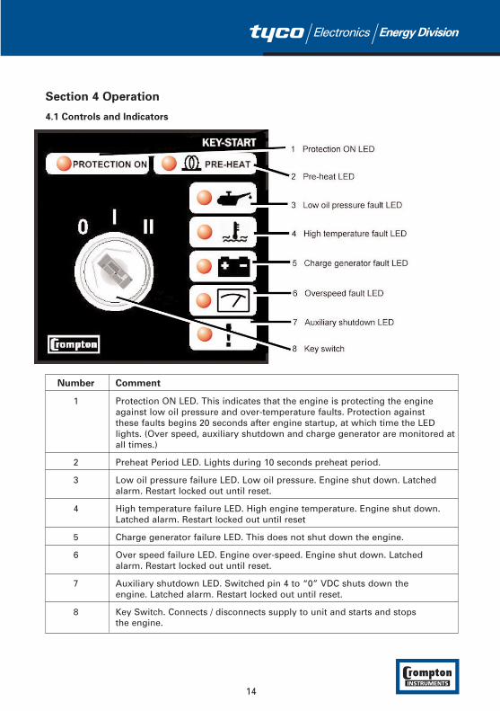
KEY-START
KEY-START-ALT
KEY-START-MAG
Manual Engine
Start Unit with Protection
Installation and Operating ManualKEY-START, -ALT, -MAG
http://energy.tycoelectronics.comEnergy Division
Tyco Electronics UK LimitedCrompton InstrumentsFreebournes Road, Witham, Essex, CM8 3AH, UKTel: +44 1376 509 509 Fax: +44 1376 509 511
Contents Page
Section 1 Introduction 3
Section 2 Installation 42.1 Unpacking 42.2 Mechanical Installation 42.3 Electrical Connections 6
2.3.1 Charge Generator current 12
Section 3 Commissioning 13
Section 4 Operation 144.1 Controls and Indicators 144.2 Starting the Engine 154.3 Stopping the Engine 15
Section 5 Fault Finding 16
Section 6 Setting Up 186.1 Meter Calibration 186.2 Speed Trip Setting 18
Section 7 Specification 19
Section 8 Index 21
Warning: The unit contains no user-serviceable items. However the KEY-START-ALT does
contain exposed parts carrying high voltages (derived from the alternator).
Any servicing must be carried out by technicians specifically trained on this type
of equipment.
Issue 1 4/2002KEYSTART MANUAL

Section 1 Introduction
The KEY-START range of Engine Protection Units provides for control and protection of agenerator set. The unit allows starting and stopping of the engine and indicates status and faultconditions. In the event of a fault, the unit automatically shuts the engine down.
Three versions of the unit are available, differing in the methods available for detection whenthe engine has started:
KEY-START Uses the output from the charge generator.
KEY-START-ALT Uses either the output from the charge generator or the alternator output
KEY-START-MAG Uses either the output from the charge generator or an input from a magnetic pickup.
Since the ALT and MAG versions can sense engine speed, they provide an output to drive atachometer.
For engine start detection, the unit assumes that the engine has started when any start sensinginput is present.
The unit monitors:
� Engine temperature, � Oil pressure, � Charging generator output,� Alternator output - ALT version only,� Magnetic pickup output – MAG version only.
The unit controls:
� Engine fuel supply, via an external solenoid,� Starter motor, via the front panel key switch,� Preheating, via a transistor output,� Alarm.
If a fault is detected, the unit shuts down the engine and indicates the failure by flashing arelevant fault LED. An Off/Run/Start key switch on the front panel controls module operation andinitiates engine cranking. An Auxiliary Shutdown input is included. If this input becomes active(low), it lights an LED and shuts down the engine.
3
Section 2 Installation
2.1 Unpacking
Carefully unpack the unit and check for damage. Retain the packing in case of future need, e.g.for returning the unit for repair.
Check the contents, as follows:
� One GEN-KEY unit. � Two Keys � Operating Manual.� Screw clamp electrical connectors.� Panel mounting clamps.
Report any shortage or damage to your local sales office as soon as possible.
2.2 Mechanical Installation
The unit is designed for panel mounting. Fixing is by two screw fixings.
Panel fascia size is 72 mm x 72 mm (2.8 in x 2.8 in). It requires a panel cut-out 69 mm x 69 mm(2.72 in x 2.72 in).
1. Remove the fixings from the unit, if fitted, and unscrew the screws in the fixings.
2. Insert the unit in the panel cut-out from the front.
3. Insert the fixings in the slotted at the diagonal corners of the unit and tighten the fixing screws to secure the unit against the panel. See Figure 2.1. Ensure that the unit is properly secured.
4
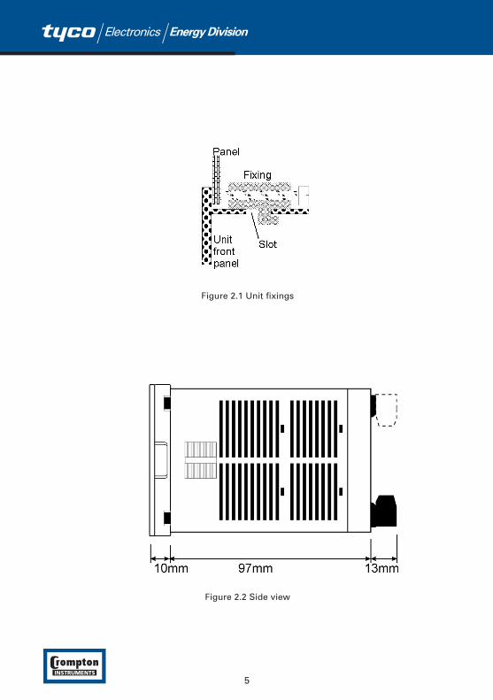
Figure 2.1 Unit fixings
Figure 2.2 Side view
5

2.3 Electrical Connections
Warning: Beware of the high voltages connected to this unit.
Figure 2.4 KEY-START-ALT rear view
Figure 2.3 KEY-START rear view
6

Figure 2.5 KEY-START-MAG rear view
Figure 2.6 KEY-START Connections schematic
7
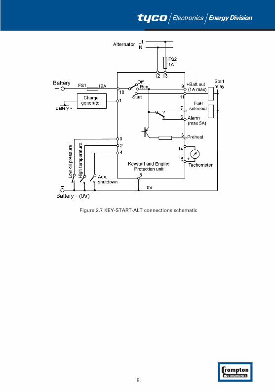
Figure 2.7 KEY-START-ALT connections schematic
8
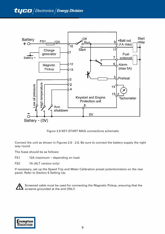
Figure 2.8 KEY-START-MAG connections schematic
Connect the unit as shown in Figures 2.6 - 2.8. Be sure to connect the battery supply the rightway round.
The fuses should be as follows:
FS1 12A maximum – depending on load.
FS2 1A (ALT version only)
If necessary, set up the Speed Trip and Meter Calibration preset potentiometers on the rearpanel. Refer to Section 6 Setting Up.
Screened cable must be used for connecting the Magnetic Pickup, ensuring that thescreenis grounded at the end ONLY.
9

10
Table 1 shows the connections and recommended cable sizes. Table 2 describes the functions ofthe connections.
Table 1 Unit wiring
Pin Description Cable Notes
size
(mm)
1 Input from Charge Generator 1.0
2 Input from Temperature Switch 1.0 Switch to "0" volt
3 Input from Oil Pressure Switch 1.0 Switch to "0" volt
4 Input from Auxiliary Shut Down Switch 1.0 Switch to "0" volt
5 Output to Pre-heat 1.0 +DC supply from key switch (not direct battery)
6 Output to Common Alarm 2.5 +DC supply from key switch
7 Output to Fuel Solenoid 2.5 +DC supply from key switch
8 Negative Battery supply to EAOM-3.2 2.5
9 + Battery Output 2.5 +DC supply from key switch
10 + Battery supply to unit. 2.5 Supplies comman alarm and external solenoid via key switch.
11 Start Output 2.5 +DC supply from key switch
KEY-START Not used. Not used.
KEY-START-ALT Alternator voltage neutral input.
KEY-START-MAG Magnetic pick-up input.
KEY-START Not used. Not used.
KEY-START-ALT Alternator voltage L1 phase input
KEY-START-MAG Magnetic pick-up input
KEY-START Not used. 1.0 Not used.
KEY-START-ALT and -MAGNegative output 0-1 mA.for tachometer.
KEY-START Not used. 1.0 Not used.
KEY-START-ALT and -MAGPositive output for tachometer.
0-1 mA.
12 1.0
1.0
1.0
1.0
13
14
15
11
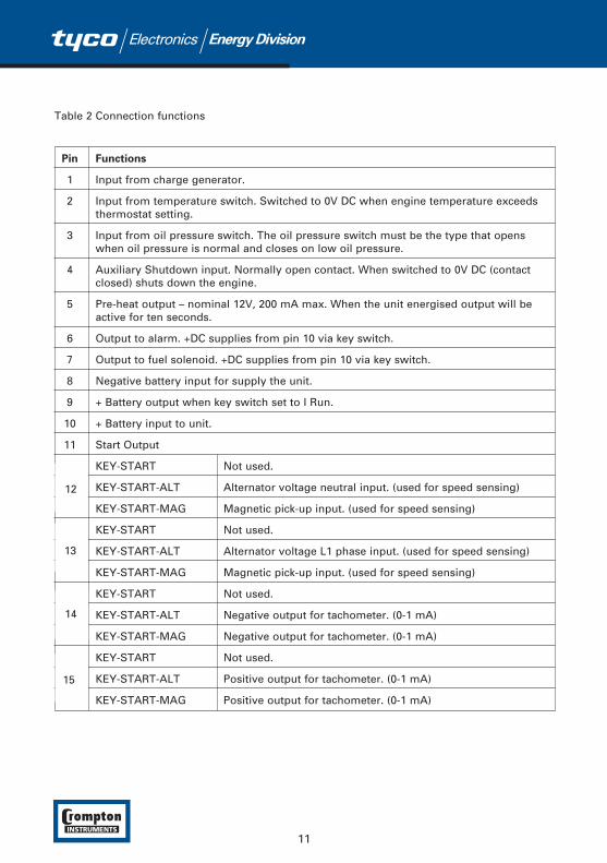
Table 2 Connection functions
Pin Functions
1 Input from charge generator.
2 Input from temperature switch. Switched to 0V DC when engine temperature exceeds thermostat setting.
3 Input from oil pressure switch. The oil pressure switch must be the type that opens when oil pressure is normal and closes on low oil pressure.
4 Auxiliary Shutdown input. Normally open contact. When switched to 0V DC (contact closed) shuts down the engine.
5 Pre-heat output – nominal 12V, 200 mA max. When the unit energised output will be active for ten seconds.
6 Output to alarm. +DC supplies from pin 10 via key switch.
7 Output to fuel solenoid. +DC supplies from pin 10 via key switch.
8 Negative battery input for supply the unit.
9 + Battery output when key switch set to I Run.
10 + Battery input to unit.
11 Start Output
KEY-START Not used.
KEY-START-ALT Alternator voltage neutral input. (used for speed sensing)
KEY-START-MAG Magnetic pick-up input. (used for speed sensing)
KEY-START Not used.
KEY-START-ALT Alternator voltage L1 phase input. (used for speed sensing)
KEY-START-MAG Magnetic pick-up input. (used for speed sensing)
KEY-START Not used.
KEY-START-ALT Negative output for tachometer. (0-1 mA)
KEY-START-MAG Negative output for tachometer. (0-1 mA)
KEY-START Not used.
KEY-START-ALT Positive output for tachometer. (0-1 mA)
KEY-START-MAG Positive output for tachometer. (0-1 mA)
15
14
13
12
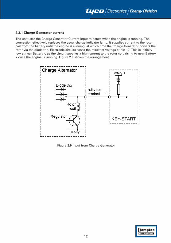
2.3.1 Charge Generator current
The unit uses the Charge Generator Current input to detect when the engine is running. Theconnection effectively replaces the usual charge indicator lamp. It supplies current to the rotorcoil from the battery until the engine is running, at which time the Charge Generator powers therotor via the diode trio. Electronic circuits sense the resultant voltage at pin 10. This is initiallylow at near Battery -, as the circuit supplies a high current to the rotor coil, rising to near Battery+ once the engine is running. Figure 2.9 shows the arrangement.
Figure 2.9 Input from Charge Generator
12
Section 3 Commissioning
Warning: Beware of the high voltages connected to the ALT version.
1. Check that the unit is correctly wired and that the wiring is of a standard and rating compatible with the system.
2. Check that the correct fuses are fitted.
3. Take temporary steps to prevent the engine from starting – for example, disable the fuel solenoid (disconnect pin 7).
4. After a visual inspection to ensure it is safe to proceed, connect the battery supply to pin 10.
5. Turn the key switch on the GEN-KEY to the Run position (I). Check that the Preheat indicator lights for ten seconds.
6. Turn the key switch to the Start position (II). Check that the starter motor runs but that the engine does not start.
7. Repeat steps 5 and 6 to confirm that the engine will not start.
8. Turn the key switch to Off (O).
9. Restore the engine to operational state (reconnect the fuel solenoid).
10. Turn the key switch to Run (I) and check that the Preheat indicator lights for ten seconds.
11. Turn the key switch to Start (II). Check that the starter motor runs and the engine starts.
12. Once the engine is running, release the switch to the Run (I) position.
13. Check that the engine runs up to its operating speed. If not and an alarm is present, check that the alarm is valid and then check the input wiring.
14. Turn the key switch to Off (O). The engine should stop.
13
Section 4 Operation
4.1 Controls and Indicators
Number Comment
1 Protection ON LED. This indicates that the engine is protecting the engine against low oil pressure and over-temperature faults. Protection against these faults begins 20 seconds after engine startup, at which time the LED lights. (Over speed, auxiliary shutdown and charge generator are monitored at all times.)
2 Preheat Period LED. Lights during 10 seconds preheat period.
3 Low oil pressure failure LED. Low oil pressure. Engine shut down. Latched alarm. Restart locked out until reset.
4 High temperature failure LED. High engine temperature. Engine shut down. Latched alarm. Restart locked out until reset
5 Charge generator failure LED. This does not shut down the engine.
6 Over speed failure LED. Engine over-speed. Engine shut down. Latched alarm. Restart locked out until reset.
7 Auxiliary shutdown LED. Switched pin 4 to “0” VDC shuts down the engine. Latched alarm. Restart locked out until reset.
8 Key Switch. Connects / disconnects supply to unit and starts and stops the engine.
14
4.2 Starting the Engine
1. Set the key switch on the front panel to the (I) Run position. The unit will power up and:� energise the fuel solenoid, activating the engine fuel system. � energise the Preheat output for ten seconds. The Preheat LED lights and the engine
ignition system preheats. After ten seconds, the Preheat output is de-energised and the Preheat LED goes Off.
� After 20 seconds, the Protection On LED lights as the unit begins monitoring for oil pressure and over-temperature faults.
2. Set the key switch on the front panel to the (II) Start position and hold it against the spring return. The unit provides an output for the start relay on pin 11. The starter should run and the engine should start.
3. When the engine has started, release the key switch to the (I) Run position.
4.3 Stopping the Engine
Set the key switch to Off (O). The engine will stop, the DC supply will be removed from the unitcircuits and the solenoid relay and alarm output de-energised. All indicators will go off.
15
Section 5 Fault Finding
Warning: Beware of the high voltages connected to the ALT version while the alternator is
running. Disconnect the unit from all electrical supplies before attempting
any maintenance.
Before carrying out any maintenance on the engine, set the key switch to Off (O) and remove
the key.
Indicators on the panel will light if a fault is detected. See Section 4.1 Controls and Indicators.Fault conditions latch so that further operation is prevented. If a fault is indicated, proceed asfollows:
1. Find and fix the fault.
2. Switch the unit off to enable a restart.
3. Restart the engine.
Any fault detected by the KEY-START unit will light an LED on the front panel and generate analarm output at pin 6 of the unit. The unit will suppress any oil pressure or high temperaturefault indications that occur in the first 20 seconds after the engine has started. After the initial 20seconds, Low Oil Pressure, High Temperature, Over Speed and Auxiliary shutdown failures willshut off the engine fuel supply to stop the engine. Any alarm condition will be latched until theKEY-START unit is switched off by turning the key switch to Off (O).
Symptom Possible remedy
Check the battery and wiring to the unit.
Check the DC supply.
Check the DC fuse. (if there is one)
Check engine oil level and pressure. Check oil pressure switch, and wiring.
Check that oil pressure switch is of the normally closed type (opens when oil pressure is normal if engine running).
Check engine temperature and cooling systems.Check temperature switch and wiring.
Check that temperature switch is of normally open type (closes on high temperature).
16
Unit is inoperative.
Oil pressure fault afterengine has started.
Engine temperature faultafter engine has fired.
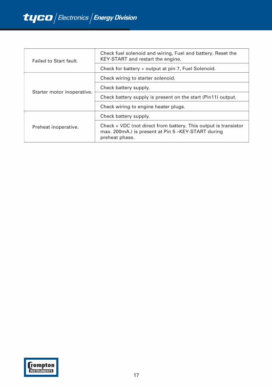
Check fuel solenoid and wiring, Fuel and battery. Reset the KEY-START and restart the engine.
Check for battery + output at pin 7, Fuel Solenoid.
Check wiring to starter solenoid.
Check battery supply.
Check battery supply is present on the start (Pin11) output.
Check wiring to engine heater plugs.
Check battery supply.
Check + VDC (not direct from battery. This output is transistor max. 200mA.) is present at Pin 5 –KEY-START during preheat phase.
17
Starter motor inoperative.
Failed to Start fault.
Preheat inoperative.
Section 6 Setting Up
The KEY-START-ALT and KEY-START-MAG can detect engine speed and so have additionalfacilities. An engine trip and alarm will occur if the engine runs over speed and a tachometer orfrequency meter can be connected to indicate engine speed/alternator frequency. Presetpotentiometers on the rear panel allow for speed trip setting and tachometer/frequency metercalibration .
6.1 Meter Calibration
The meter output is designed for a 1 mA fsd 75 Ohm meter.
The factory default settings are as follows:
KEY-START-ALT 50 Hz nominal alternator frequency gives 0.75 mA.
KEY-START-MAG 1500 rev/min nominal engine speed with 172 flywheel teeth gives 0.75 mA
1. Set the engine to run at its nominal speed and measure the alternator output frequency or engine speed.
2. If the meter is calibrated (in Hz or Revs/Min), adjust the Meter Calibration preset so that the meter reads the correct value for the measured alternator frequency/engine speed. Alternatively, the preset should be set for 75% of fsd at the nominal engine speed such that the full scale range is 0 (0 mA) to 130% (1 mA) of engine nominal speed (this is the factory default).
6.2 Speed Trip Setting
The factory default settings are as follows:
KEY-START-ALT trips at 57.5 Hz
KEY-START-mag trips at 1500 rev/min.
1. Set the Speed Trip preset fully counterclockwise.
2. Disconnect the load from the alternator.
3. Measure the alternator output frequency.
4. Start up the engine and adjust the engine speed for the maximum permitted alternator output frequency; e.g. 57.5 Hz for 50 Hz nominal or 69 Hz for 60 Hz nominal.
5. Carefully turn the Speed Trip preset clockwise until the Over Speed LED lights and the engine shuts down.
6. Reduce the engine speed setting, restart the engine, increase the engine speed and check that an overspeed shut down occurs at the preset high alternator output frequency (e.g. 57.5 or 69 Hz).
18
Section 7 Specification
Inputs
DC Supply 8 to 32V DC
Operating Current 200mA maximum
Cranking Dropout Battery voltage can be 0V DC for max. 100 ms during cranking (battery voltage should be at least nominal voltage before cranking)
Generator Voltage 35 to 300V AC L-N, 10 to 110Hz (KEY-START-ALT)Neutral and battery negative must be grounded.
Magnetic Pickup 3 to 35 Volts peak, 35Hz to 10kHz (KEY-START-MAG)
Contact Sensing Oil Pressure Switch (NC)Temperature Switch (NO)Auxiliary Shutdown (NO)
Tachometer 0 to 1 mA DC into 75 Ohm meter
Outputs
Relay Contacts Start relay (12 Amp DC at 12/24V)Fuel relay (12 Amp DC at 12/24V)Horn relay (5 Amp DC at 12/24V)Preheat output (200mA maximum at 12/24V DC)
Charge Generator Excitation current 200mA, maximum 3 Watts.
Display
Failure Annunciators Low Oil PressureHigh TemperatureCharging FailOver SpeedAuxiliary Shutdown
Status Annunciators Protection OnPreheating On
Measurement Accuracy
Generator Frequency 1% of full scale, 10 - 110 Hz alternator Voltage
Engine Speed 0.25% of full scale, 35 - 10,000Hz magnetic pickup
Overspeed Trip 1% of full scale
Environmental
Operating Temperature -25°C to +70°C (-13°F to +158°F)
Storage Temperature -40°C to +85°C (-40°F to +185°F)
Humidity <93% RH, non condensing
Environmental Rating Standard, Indoors, Altitude less than 2000m
Mode of operation Continuous
19
Standards
EMC BS EN 50081-2, BS EN 50082-2
Electrical Safety EN 61010-1
Installation Category II
Pollution Degree II
Mechanical
Enclosure DIN 43700 Style housing, 72mm x 72mm Bezel, 69mm x 69mm cutout
Panel Thickness 10mm (0.4 in) Maximum
Protection Class IP30 front panel, IP20 rear panel
Weight Approximately 0.4 Kg
Range of calibration (Rear adjustments)
KEY-START-ALT Meter calibration adjustment range 25% - 200% of nominal frequencyOverspeed Trip adjustment range 10 - 110 Hz
KEY-START-MAG Meter calibration adjustment range 25% - 200% of nominal RPMOverspeed Trip adjustment range 35Hz to 10kHz
Preset Operating Parameters
Protection on delay: Engine faults other than over-temperature are not reported for the first 20 seconds from power-on.
Preheating duration: Energised for 10 seconds from power-on.
Factory Settings as supplied
KEY-START-ALT 50Hz Nominal, tachometer output 0/1mA = 0/66.7 Hz
Overspeed Trip is preset to 57.5 Hz
KEY-START-MAG 1500 RPM Nominal, 172 Teeth, tachometer output 0/1mA = 0/2000 RPMOverspeed Trip is preset to 1725 RPM
Accessories: Spare keys are available for these units. The ordercode for these is: SPARE-KEY-KS
20
Index
Auxiliary shutdown, 14, 16, 20
Charge generator, 12, 14
Connections, 7, 8, 9
Cut-out size, 4
EMC, 19
Engine start detection, 12
Factory defaults, 18
Fascia size, 4
Fixings, 4
Fuses, 9
High temperature, 16
Key switch, 3, 15
Meter calibration, 18
21
Oil pressure, 14, 16, 20
Over speed, 14, 16
Over-temperature, 14
Preheat, 14
Protection ON LED, 14
Rear view, 6, 7
Setting up, 18
Speed trip, 18
Unpacking, 4
Warnings, 2

http://energy.tycoelectronics.com
Tyco Electronics UK LimitedCrompton InstrumentsFreebournes Road, Witham, Essex, CM8 3AH, UKTel: +44 1376 509 509 Fax: +44 1376 509 511
The Information contained in these installation instructions is for use only by installers trained to make electrical power installations and is intendedto describe the correct method of installation for this product. However, Tyco Electronics has no control over the field conditions which influenceproduct installation. It is the user's responsibility to determine the suitability of the installation method in the user's field conditions. Tyco Electronics' only obligationsare those in Tyco Electronics' standard Conditions of Sale for this product and in no case will Tyco Electronics be liable for any other incidental,indirect or consequential damages arising from the use or misuse of the products. Crompton is a trade mark.


![Avira User Manual€¦ · Avira Rescue System - User Manual (Status: 25 Jun. 2013) 7 [Alt] + N Next, to start a scan [Alt] + P Pause the scanning process [Alt] + R Resume the paused](https://img.pdfslide.us/doc/110x75/5f0803de7e708231d41fe756/avira-user-manual-avira-rescue-system-user-manual-status-25-jun-2013-7-alt.jpg)