Embed Size (px)
Citation preview
OWNER’S MANUALINSTALLATION AND OPERATING INSTRUCTIONS
PVM (IX) 2 - PVM (IX) 16
VERTICAL MULTISTAGE PUMPSSingle and Three Phase 60 Cycle
Record the following information from the motor and pumpnameplates for future reference:
Pump Model No.
Bill of Material No.
Motor Model No.
Motor Serial No.
H.P. Volts/Hz/Ph
Rated Amp Draw
Aurora Pump, 800 Airport Road, North Aurora, IL 60542
AP473 (10/1/06)
TABLE OF CONTENTS Safety Instructions..............................................................2Applications and Operating Ranges................................2-4Installation.........................................................................5Electrical ........................................................................6-7Operation.......................................................................7-8Maintenance ................................................................9-12Troubleshooting Guide....................................................13Repair Parts ................................................................14-17
Carefully read and follow all safety instructionsin this manual or on pump.
This is the safety-alert. When you see this symbol onyour pump or in this manual, look for one of the
following signal words and be alert to the potential forpersonal injury.
warns about hazards that will cause seriouspersonal injury, death or major property damage if ignored.
warns about hazards that can cause seriouspersonal injury, death or major property damage if ignored.
warns about hazards that will or can causeminor personal injury or property damage if ignored.
The word NOTICE indicates special instructions which areimportant but not related to hazards.
To avoid serious or fatal personal injury and possibleproperty damage, carefully read and follow the safetyinstructions.
1. Install pump according to all code requirements.
2. Compare pump nameplate data with desired operatingrange.
3. Pump only liquids compatible with pump componentmaterials (that is, liquids that will not attack the pump).
4. Make sure plumbing is adequate to handle systempressure.
5. Periodically perform maintenance inspection on pumpand system components.
6. Wear safety glasses at all times when working onpumps.
INSPECT THE SHIPMENTThe vertical multistage centrifugal inline pump has beencarefully inspected and packaged to assure safe delivery.Inspect the pump and fittings and report to the carrier anyitems which are damaged or missing.
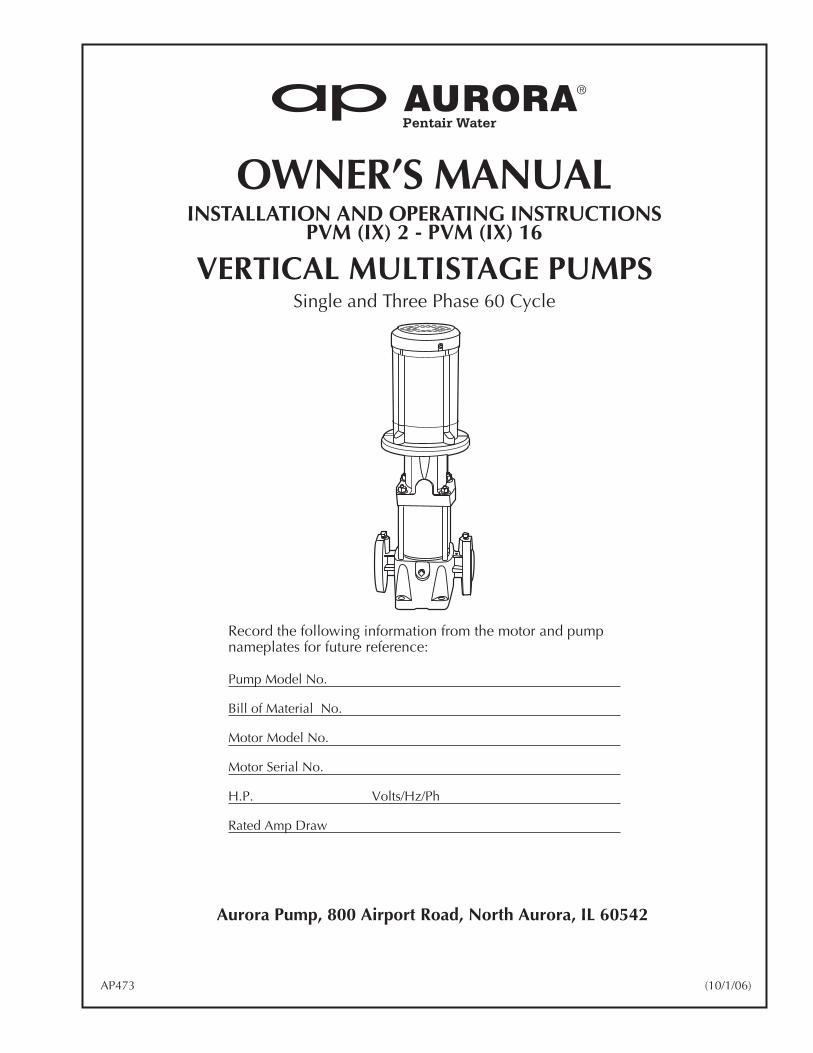
CONFIRM THAT YOU HAVE THE RIGHT PUMP
APPLICATIONS AND OPERATING RANGESAurora multistage in-line centrifugal pumps are designedfor liquid transfer, circulation, and pressure boosting of hotor cold clean water or other thin, non-explosive liquids, notcontaining solid particles or fibers, which will notchemically attack the pump materials.
Typical applications include:
• Municipal water supply and pressure boosting
• Boiler feed and condensate systems
• Cooling water systems
• Irrigation
• Fire fighting
Maximum Ambient Temperature....................104° F(40° C)
Liquid Temperature Range .............................5° F to 250° F(-15° C to +121° C)
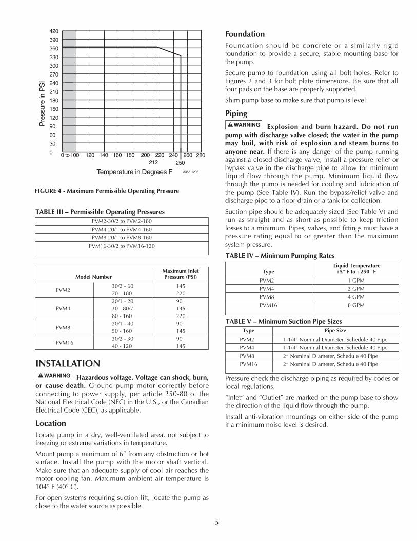
Maximum Permissible Operating Pressure Curves................................See Figure 4
Maximum Inlet Pressure: ....... Table II shows the maximum permissible inlet pressure. However,
the actual inlet pressure plus the pressure when the pump is running against a closed
valve must always be lower than the “Maximum Permissible Operating Pressure”.
Electrical Data: ..................................See Motor Nameplate
Dimensions and Port to Port Lengths : ...................................See Figures 2A, 2B, 3A
and 3B, Pages 3 and 4
2
PVM_2-30/2Aurora VerticalMultistage Pump
Nominal flow rate in m3/hr(multiply by 4.4 to get GPM)
Number of stages ( 10)
Number of impellers - only used if pumphas fewer impellers than chambers (stages)
Material Code (SS only)I = all wetted surfaces 304SS; X = all wetted surfaces 316SS
MODEL #
GPM
HP
PART #
FEET
PRESS. MAX (PSI)
MFG. DATE
RPM
TEMP. MAX (F)
FIGURE 1 - Model Plate Information
3
3"
9-7/8"
3-15/16"
7-1/16"8-1/4"
3-15/16"
8-1/4"
10"
1-1/4"NPT
ANSI 250 lb1-1/4" Flange
1/2" Dia. – 4 Places
E
A
B
CD
EA
B
CD
F F
1/4" NPTGauge Tap
3/4" NPTVent Plug
Allow Spaceto Remove Motor
1/4" NPTGauge Tap
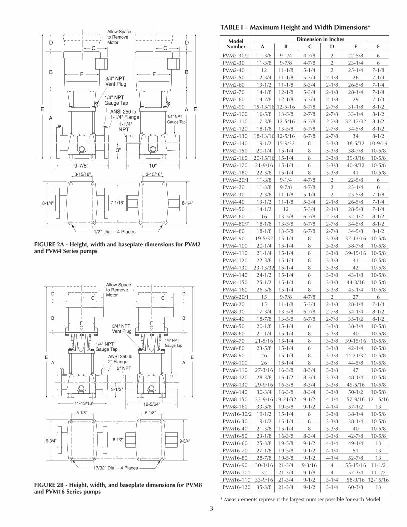
FIGURE 2A - Height, width and baseplate dimensions for PVM2and PVM4 Series pumps
11-13/16"
5-1/8"5-1/8"
8-1/2"9-3/4"
3-1/2"
12-5/64"
2" NPT
ANSI 250 lb2" Flange
17/32" Dia. – 4 Places
E
B
D
A
C
E
B
D
A
C
F F
9-3/4"
Allow Spaceto Remove Motor
1/4" NPTGauge Tap
1/4" NPTGauge Tap
3/4" NPTVent Plug
FIGURE 2B - Height, width, and baseplate dimensions for PVM8and PVM16 Series pumps
Model Dimension in InchesNumber A B C D E F
PVM2-30/2 11-3/8 9-1/4 4-7/8 2 22-5/8 6PVM2-30 11-3/8 9-7/8 4-7/8 2 23-1/4 6PVM2-40 12 11-1/8 5-1/4 2 25-1/4 7-1/8PVM2-50 12-3/4 11-1/8 5-3/4 2-1/8 26 7-1/4PVM2-60 13-1/2 11-1/8 5-3/4 2-1/8 26-5/8 7-1/4PVM2-70 14-1/8 12-1/8 5-3/4 2-1/8 28-1/4 7-1/4PVM2-80 14-7/8 12-1/8 5-3/4 2-1/8 29 7-1/4PVM2-90 15-15/16 12-5-16 6-7/8 2-7/8 31-1/8 8-1/2PVM2-100 16-5/8 13-5/8 2-7/8 2-7/8 33-1/4 8-1/2PVM2-110 17-3/8 12-5/16 6-7/8 2-7/8 32-17/32 8-1/2PVM2-120 18-1/8 13-5/8 6-7/8 2-7/8 34-5/8 8-1/2PVM2-130 18-13/16 12-5/16 6-7/8 2-7/8 34 8-1/2PVM2-140 19-1/2 15-9/32 8 3-3/8 38-5/32 10-9/16PVM2-150 20-1/4 15-1/4 8 3-3/8 38-7/8 10-5/8PVM2-160 20-15/16 15-1/4 8 3-3/8 39-9/16 10-5/8PVM2-170 21-9/16 15-1/4 8 3-3/8 40-9/32 10-5/8PVM2-180 22-3/8 15-1/4 8 3-3/8 41 10-5/8PVM4-20/1 11-3/8 9-1/4 4-7/8 2 22-5/8 6PVM4-20 11-3/8 9-7/8 4-7/8 2 23-1/4 6PVM4-30 12-3/8 11-1/8 5-1/4 2 25-5/8 7-1/8PVM4-40 13-1/2 11-1/8 5-3/4 2-1/8 26-5/8 7-1/4PVM4-50 14-1/2 12 5-3/4 2-1/8 28-5/8 7-1/4PVM4-60 16 13-5/8 6-7/8 2-7/8 32-1/2 8-1/2PVM4-80/7 18-1/8 13-5/8 6-7/8 2-7/8 34-5/8 8-1/2PVM4-80 18-1/8 13-5/8 6-7/8 2-7/8 34-5/8 8-1/2PVM4-90 19-5/32 15-1/4 8 3-3/8 37-13/16 10-5/8PVM4-100 20-1/4 15-1/4 8 3-3/8 38-7/8 10-5/8PVM4-110 21-1/4 15-1/4 8 3-3/8 39-15/16 10-5/8PVM4-120 22-3/8 15-1/4 8 3-3/8 41 10-5/8PVM4-130 23-13/32 15-1/4 8 3-3/8 42 10-5/8PVM4-140 24-1/2 15-1/4 8 3-3/8 43-1/8 10-5/8PVM4-150 25-1/2 15-1/4 8 3-3/8 44-3/16 10-5/8PVM4-160 26-5/8 15-1/4 8 3-3/8 45-1/4 10-5/8PVM8-20/1 15 9-7/8 4-7/8 2 27 6PVM8-20 15 11-1/8 5-3/4 2-1/8 28-1/4 7-1/4PVM8-30 17-3/4 13-5/8 6-7/8 2-7/8 34-1/4 8-1/2PVM8-40 18-7/8 13-5/8 6-7/8 2-7/8 35-1/2 8-1/2PVM8-50 20-1/8 15-1/4 8 3-3/8 38-3/4 10-5/8PVM8-60 21-1/4 15-1/4 8 3-3/8 40 10-5/8PVM8-70 21-5/16 15-1/4 8 3-3/8 39-15/16 10-5/8PVM8-80 23-5/8 15-1/4 8 3-3/8 42-1/4 10-5/8PVM8-90 26 15-1/4 8 3-3/8 44-21/32 10-5/8PVM8-100 26 15-1/4 8 3-3/8 44-5/8 10-5/8PVM8-110 27-3/16 16-3/8 8-3/4 3-3/8 47 10-5/8PVM8-120 28-3/8 16-1/2 8-3/4 3-3/8 48-1/4 10-5/8PVM8-130 29-9/16 16-3/8 8-3/4 3-3/8 49-5/16 10-5/8PVM8-140 30-3/4 16-3/8 8-3/4 3-3/8 50-1/2 10-5/8PVM8-150 33-9/16 19-21/32 9-1/2 4-1/4 57-9/16 12-15/16PVM8-160 33-5/8 19-5/8 9-1/2 4-1/4 57-1/2 13PVM16-30/2 19-1/2 15-1/4 8 3-3/8 38-1/4 10-5/8PVM16-30 19-1/2 15-1/4 8 3-3/8 38-1/4 10-5/8PVM16-40 21-3/8 15-1/4 8 3-3/8 40 10-5/8PVM16-50 23-1/8 16-3/8 8-3/4 3-3/8 42-7/8 10-5/8PVM16-60 25-3/8 19-5/8 9-1/2 4-1/4 49-1/4 13PVM16-70 27-1/8 19-5/8 9-1/2 4-1/4 51 13PVM16-80 28-7/8 19-5/8 9-1/2 4-1/4 52-7/8 13PVM16-90 30-3/16 21-3/4 9-3/16 4 55-15/16 11-1/2PVM16-100 32 21-3/4 9-1/8 4 57-3/4 11-1/2PVM16-110 33-9/16 21-3/4 9-1/2 3-1/4 58-9/16 12-15/16PVM16-120 35-3/8 21-3/4 9-1/2 3-1/4 60-3/8 13
TABLE I – Maximum Height and Width Dimensions*
* Measurements represent the largest number possible for each Model.
4
3"
9-7/8"
3-15/16"
7-3/32"8-3/16"
3-15/16"
8-3/16"
8-1/4"
ANSI 250 lb1-1/4" Flange
17/32" Dia. – 4 Places
E
A
B
CD
EA
B
D
F
C
F
Allow Spaceto Remove Motor
1-1/4"Victaulic
Vent Plugbehind
Coupling Guard
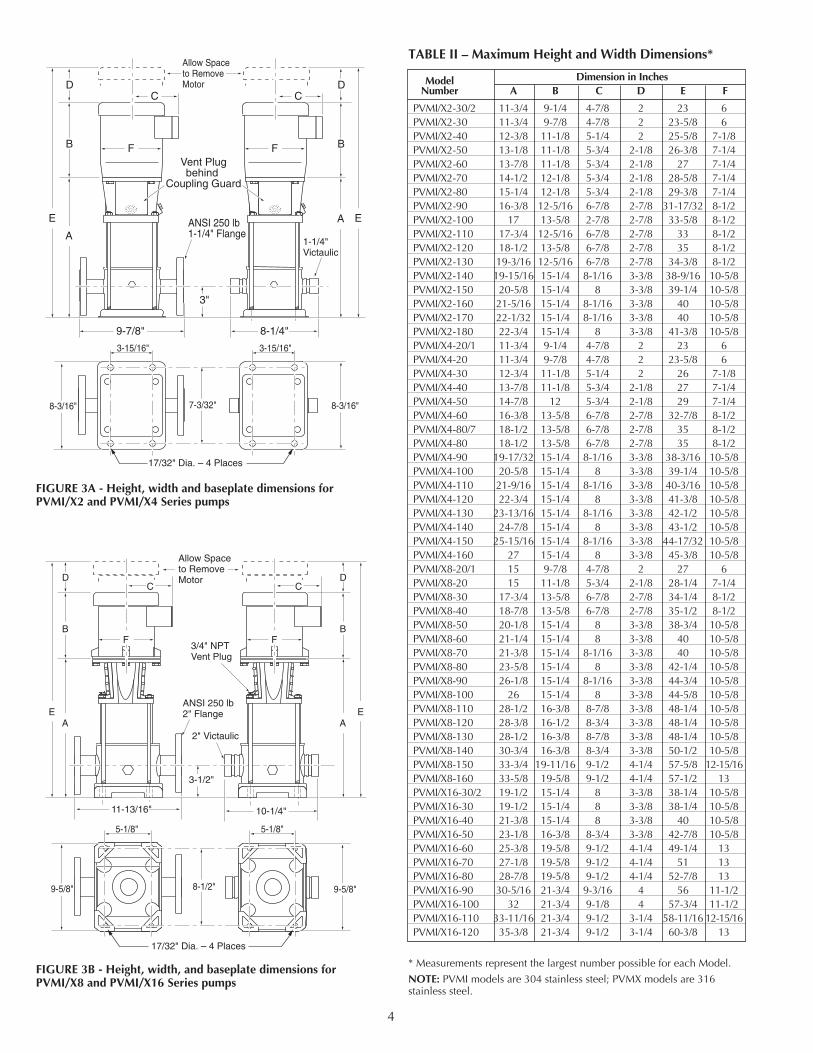
FIGURE 3A - Height, width and baseplate dimensions forPVMI/X2 and PVMI/X4 Series pumps
11-13/16"
5-1/8"5-1/8"
8-1/2"9-5/8"
3-1/2"
2" Victaulic
ANSI 250 lb2" Flange
17/32" Dia. – 4 Places
E
B
D
A
C
E
B
D
A
C
F F
9-5/8"
Allow Spaceto Remove Motor
3/4" NPTVent Plug
10-1/4"
FIGURE 3B - Height, width, and baseplate dimensions forPVMI/X8 and PVMI/X16 Series pumps
Model Dimension in InchesNumber A B C D E F
PVMI/X2-30/2 11-3/4 9-1/4 4-7/8 2 23 6PVMI/X2-30 11-3/4 9-7/8 4-7/8 2 23-5/8 6PVMI/X2-40 12-3/8 11-1/8 5-1/4 2 25-5/8 7-1/8PVMI/X2-50 13-1/8 11-1/8 5-3/4 2-1/8 26-3/8 7-1/4PVMI/X2-60 13-7/8 11-1/8 5-3/4 2-1/8 27 7-1/4PVMI/X2-70 14-1/2 12-1/8 5-3/4 2-1/8 28-5/8 7-1/4PVMI/X2-80 15-1/4 12-1/8 5-3/4 2-1/8 29-3/8 7-1/4PVMI/X2-90 16-3/8 12-5/16 6-7/8 2-7/8 31-17/32 8-1/2PVMI/X2-100 17 13-5/8 2-7/8 2-7/8 33-5/8 8-1/2PVMI/X2-110 17-3/4 12-5/16 6-7/8 2-7/8 33 8-1/2PVMI/X2-120 18-1/2 13-5/8 6-7/8 2-7/8 35 8-1/2PVMI/X2-130 19-3/16 12-5/16 6-7/8 2-7/8 34-3/8 8-1/2PVMI/X2-140 19-15/16 15-1/4 8-1/16 3-3/8 38-9/16 10-5/8PVMI/X2-150 20-5/8 15-1/4 8 3-3/8 39-1/4 10-5/8PVMI/X2-160 21-5/16 15-1/4 8-1/16 3-3/8 40 10-5/8PVMI/X2-170 22-1/32 15-1/4 8-1/16 3-3/8 40 10-5/8PVMI/X2-180 22-3/4 15-1/4 8 3-3/8 41-3/8 10-5/8PVMI/X4-20/1 11-3/4 9-1/4 4-7/8 2 23 6PVMI/X4-20 11-3/4 9-7/8 4-7/8 2 23-5/8 6PVMI/X4-30 12-3/4 11-1/8 5-1/4 2 26 7-1/8PVMI/X4-40 13-7/8 11-1/8 5-3/4 2-1/8 27 7-1/4PVMI/X4-50 14-7/8 12 5-3/4 2-1/8 29 7-1/4PVMI/X4-60 16-3/8 13-5/8 6-7/8 2-7/8 32-7/8 8-1/2PVMI/X4-80/7 18-1/2 13-5/8 6-7/8 2-7/8 35 8-1/2PVMI/X4-80 18-1/2 13-5/8 6-7/8 2-7/8 35 8-1/2PVMI/X4-90 19-17/32 15-1/4 8-1/16 3-3/8 38-3/16 10-5/8PVMI/X4-100 20-5/8 15-1/4 8 3-3/8 39-1/4 10-5/8PVMI/X4-110 21-9/16 15-1/4 8-1/16 3-3/8 40-3/16 10-5/8PVMI/X4-120 22-3/4 15-1/4 8 3-3/8 41-3/8 10-5/8PVMI/X4-130 23-13/16 15-1/4 8-1/16 3-3/8 42-1/2 10-5/8PVMI/X4-140 24-7/8 15-1/4 8 3-3/8 43-1/2 10-5/8PVMI/X4-150 25-15/16 15-1/4 8-1/16 3-3/8 44-17/32 10-5/8PVMI/X4-160 27 15-1/4 8 3-3/8 45-3/8 10-5/8PVMI/X8-20/1 15 9-7/8 4-7/8 2 27 6PVMI/X8-20 15 11-1/8 5-3/4 2-1/8 28-1/4 7-1/4PVMI/X8-30 17-3/4 13-5/8 6-7/8 2-7/8 34-1/4 8-1/2PVMI/X8-40 18-7/8 13-5/8 6-7/8 2-7/8 35-1/2 8-1/2PVMI/X8-50 20-1/8 15-1/4 8 3-3/8 38-3/4 10-5/8PVMI/X8-60 21-1/4 15-1/4 8 3-3/8 40 10-5/8PVMI/X8-70 21-3/8 15-1/4 8-1/16 3-3/8 40 10-5/8PVMI/X8-80 23-5/8 15-1/4 8 3-3/8 42-1/4 10-5/8PVMI/X8-90 26-1/8 15-1/4 8-1/16 3-3/8 44-3/4 10-5/8PVMI/X8-100 26 15-1/4 8 3-3/8 44-5/8 10-5/8PVMI/X8-110 28-1/2 16-3/8 8-7/8 3-3/8 48-1/4 10-5/8PVMI/X8-120 28-3/8 16-1/2 8-3/4 3-3/8 48-1/4 10-5/8PVMI/X8-130 28-1/2 16-3/8 8-7/8 3-3/8 48-1/4 10-5/8PVMI/X8-140 30-3/4 16-3/8 8-3/4 3-3/8 50-1/2 10-5/8PVMI/X8-150 33-3/4 19-11/16 9-1/2 4-1/4 57-5/8 12-15/16PVMI/X8-160 33-5/8 19-5/8 9-1/2 4-1/4 57-1/2 13PVMI/X16-30/2 19-1/2 15-1/4 8 3-3/8 38-1/4 10-5/8PVMI/X16-30 19-1/2 15-1/4 8 3-3/8 38-1/4 10-5/8PVMI/X16-40 21-3/8 15-1/4 8 3-3/8 40 10-5/8PVMI/X16-50 23-1/8 16-3/8 8-3/4 3-3/8 42-7/8 10-5/8PVMI/X16-60 25-3/8 19-5/8 9-1/2 4-1/4 49-1/4 13PVMI/X16-70 27-1/8 19-5/8 9-1/2 4-1/4 51 13PVMI/X16-80 28-7/8 19-5/8 9-1/2 4-1/4 52-7/8 13PVMI/X16-90 30-5/16 21-3/4 9-3/16 4 56 11-1/2PVMI/X16-100 32 21-3/4 9-1/8 4 57-3/4 11-1/2PVMI/X16-110 33-11/16 21-3/4 9-1/2 3-1/4 58-11/16 12-15/16PVMI/X16-120 35-3/8 21-3/4 9-1/2 3-1/4 60-3/8 13
TABLE II – Maximum Height and Width Dimensions*
* Measurements represent the largest number possible for each Model.
NOTE: PVMI models are 304 stainless steel; PVMX models are 316stainless steel.
5
INSTALLATIONHazardous voltage. Voltage can shock, burn,
or cause death. Ground pump motor correctly beforeconnecting to power supply, per article 250-80 of theNational Electrical Code (NEC) in the U.S., or the CanadianElectrical Code (CEC), as applicable.
LocationLocate pump in a dry, well-ventilated area, not subject tofreezing or extreme variations in temperature.
Mount pump a minimum of 6” from any obstruction or hotsurface. Install the pump with the motor shaft vertical.Make sure that an adequate supply of cool air reaches themotor cooling fan. Maximum ambient air temperature is104° F (40° C).
For open systems requiring suction lift, locate the pump asclose to the water source as possible.
FoundationFoundation should be concrete or a similarly rigidfoundation to provide a secure, stable mounting base forthe pump.
Secure pump to foundation using all bolt holes. Refer toFigures 2 and 3 for bolt plate dimensions. Be sure that allfour pads on the base are properly supported.
Shim pump base to make sure that pump is level.
Piping
Explosion and burn hazard. Do not runpump with discharge valve closed; the water in the pumpmay boil, with risk of explosion and steam burns toanyone near. If there is any danger of the pump runningagainst a closed discharge valve, install a pressure relief orbypass valve in the discharge pipe to allow for minimumliquid flow through the pump. Minimum liquid flowthrough the pump is needed for cooling and lubrication ofthe pump (See Table IV). Run the bypass/relief valve anddischarge pipe to a floor drain or a tank for collection.
Suction pipe should be adequately sized (See Table V) andrun as straight and as short as possible to keep frictionlosses to a minimum. Pipes, valves, and fittings must have apressure rating equal to or greater than the maximumsystem pressure.
Pressure check the discharge piping as required by codes orlocal regulations.
“Inlet” and “Outlet” are marked on the pump base to showthe direction of the liquid flow through the pump.
Install anti-vibration mountings on either side of the pumpif a minimum noise level is desired.
Liquid TemperatureType +5° F to +250° F
PVM2 1 GPM
PVM4 2 GPM
PVM8 4 GPM
PVM16 8 GPM
TABLE IV – Minimum Pumping Rates
Type Pipe Size
PVM2 1-1/4” Nominal Diameter, Schedule 40 Pipe
PVM4 1-1/4” Nominal Diameter, Schedule 40 Pipe
PVM8 2” Nominal Diameter, Schedule 40 Pipe
PVM16 2” Nominal Diameter, Schedule 40 Pipe
TABLE V – Minimum Suction Pipe Sizes
FIGURE 4 - Maximum Permissible Operating Pressure
0
30
60
90
120
150
180
210
240
270
300
330
360
390
420
2120 to100 120 140 160 180 200 220 240
250260 280
Pre
ssur
e in
PS
I
Temperature in Degrees F 3355 1298
PVM2-30/2 to PVM2-180
PVM4-20/1 to PVM4-160
PVM8-20/1 to PVM8-160
PVM16-30/2 to PVM16-120
TABLE III – Permissible Operating Pressures
Maximum InletModel Number Pressure (PSI)
PVM230/2 - 60 14570 - 180 22020/1 - 20 90
PVM4 30 - 80/7 14580 - 160 220
PVM820/1 - 40 9050 - 160 145
PVM1630/2 - 30 9040 - 120 145
6
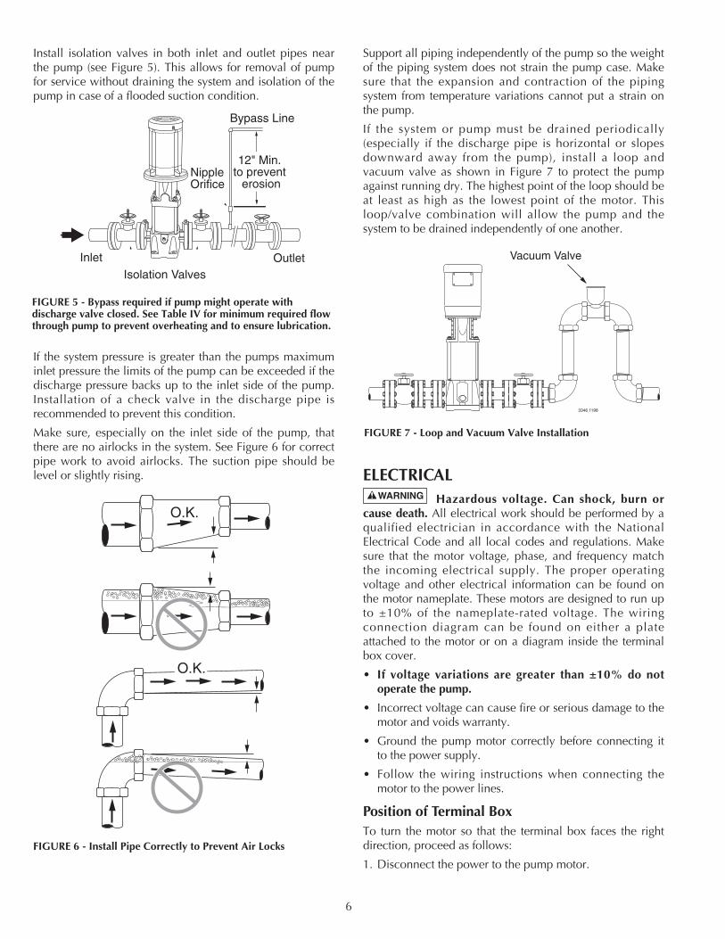
Install isolation valves in both inlet and outlet pipes nearthe pump (see Figure 5). This allows for removal of pumpfor service without draining the system and isolation of thepump in case of a flooded suction condition.
If the system pressure is greater than the pumps maximuminlet pressure the limits of the pump can be exceeded if thedischarge pressure backs up to the inlet side of the pump.Installation of a check valve in the discharge pipe isrecommended to prevent this condition.
Make sure, especially on the inlet side of the pump, thatthere are no airlocks in the system. See Figure 6 for correctpipe work to avoid airlocks. The suction pipe should belevel or slightly rising.
Support all piping independently of the pump so the weightof the piping system does not strain the pump case. Makesure that the expansion and contraction of the pipingsystem from temperature variations cannot put a strain onthe pump.
If the system or pump must be drained periodically(especially if the discharge pipe is horizontal or slopesdownward away from the pump), install a loop andvacuum valve as shown in Figure 7 to protect the pumpagainst running dry. The highest point of the loop should beat least as high as the lowest point of the motor. Thisloop/valve combination will allow the pump and thesystem to be drained independently of one another.
ELECTRICALHazardous voltage. Can shock, burn or
cause death. All electrical work should be performed by aqualified electrician in accordance with the NationalElectrical Code and all local codes and regulations. Makesure that the motor voltage, phase, and frequency matchthe incoming electrical supply. The proper operatingvoltage and other electrical information can be found onthe motor nameplate. These motors are designed to run upto ±10% of the nameplate-rated voltage. The wiringconnection diagram can be found on either a plateattached to the motor or on a diagram inside the terminalbox cover.
• If voltage variations are greater than ±10% do notoperate the pump.
• Incorrect voltage can cause fire or serious damage to themotor and voids warranty.
• Ground the pump motor correctly before connecting itto the power supply.
• Follow the wiring instructions when connecting themotor to the power lines.
Position of Terminal BoxTo turn the motor so that the terminal box faces the rightdirection, proceed as follows:
1. Disconnect the power to the pump motor.
O.K.
O.K.
FIGURE 6 - Install Pipe Correctly to Prevent Air Locks
3346 1198
Vacuum Valve
FIGURE 7 - Loop and Vacuum Valve Installation
FIGURE 5 - Bypass required if pump might operate withdischarge valve closed. See Table IV for minimum required flowthrough pump to prevent overheating and to ensure lubrication.
Inlet Outlet
NippleOrifice
Bypass Line
12" Min. to prevent
erosion
Isolation Valves
7
2. Remove the coupling guards (use a screwdriver).
3. Remove the couplings.
4. Remove the bolts that fasten the motor to the pump.
5. Turn the motor to the required position (in quarter-turnincrements).
6. Follow steps 10 - 20 under “Motor Replacement”, onPage 9.
Field WiringAll wiring connections and wiring sizes must meet NationalElectrical Code and local requirements.
Motor ProtectionSee the motor nameplate for electrical connection/wiringdiagram.
Aurora pumps must be used with the proper size and typeof motor starter to ensure protection against damage fromlow voltage, phase failure, current imbalances andoverloads. The overload should be sized to trip at the full-load current rating of the motor.
OPERATIONPriming
Hazardous pressure. Do not run the pumpwith the discharge valve closed; the water in the pump mayboil, causing risk of explosion and steam burns to anyonenearby.
Hazardous voltage. Disconnect all power tothe pump before servicing or working on the pump. Makesure that the power is locked out and that the pump cannotbe accidentally started.
NOTICE: Under no circumstances should the pump beoperated without flow through the pump. Never operatethe pump dry.
Operation of closed systems or open systems with theliquid level above the pump priming plug:
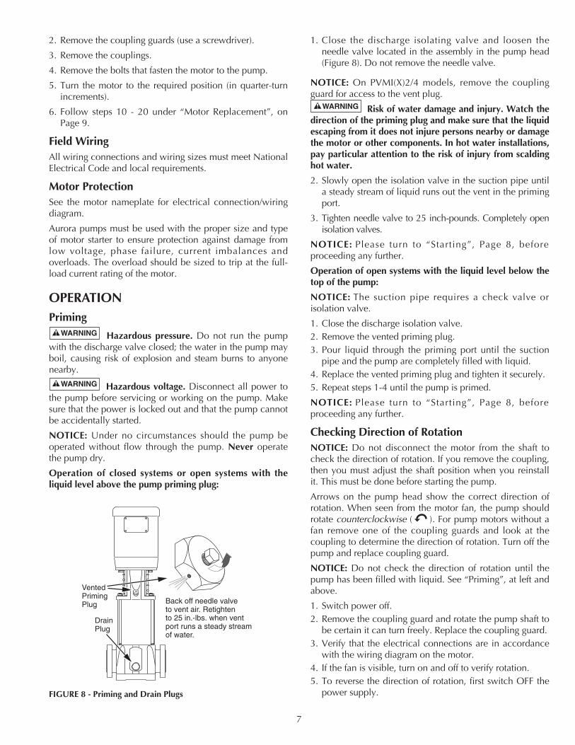
1. Close the discharge isolating valve and loosen theneedle valve located in the assembly in the pump head(Figure 8). Do not remove the needle valve.
NOTICE: On PVMI(X)2/4 models, remove the couplingguard for access to the vent plug.
Risk of water damage and injury. Watch thedirection of the priming plug and make sure that the liquidescaping from it does not injure persons nearby or damagethe motor or other components. In hot water installations,pay particular attention to the risk of injury from scaldinghot water.
2. Slowly open the isolation valve in the suction pipe untila steady stream of liquid runs out the vent in the primingport.
3. Tighten needle valve to 25 inch-pounds. Completely openisolation valves.
NOTICE: Please turn to “Starting”, Page 8, beforeproceeding any further.
Operation of open systems with the liquid level below thetop of the pump:
NOTICE: The suction pipe requires a check valve orisolation valve.
1. Close the discharge isolation valve.2. Remove the vented priming plug.3. Pour liquid through the priming port until the suction
pipe and the pump are completely filled with liquid.4. Replace the vented priming plug and tighten it securely.5. Repeat steps 1-4 until the pump is primed.
NOTICE: Please turn to “Starting”, Page 8, beforeproceeding any further.
Checking Direction of RotationNOTICE: Do not disconnect the motor from the shaft tocheck the direction of rotation. If you remove the coupling,then you must adjust the shaft position when you reinstallit. This must be done before starting the pump.
Arrows on the pump head show the correct direction ofrotation. When seen from the motor fan, the pump shouldrotate counterclockwise ( ). For pump motors without afan remove one of the coupling guards and look at thecoupling to determine the direction of rotation. Turn off thepump and replace coupling guard.
NOTICE: Do not check the direction of rotation until thepump has been filled with liquid. See “Priming”, at left andabove.
1. Switch power off.2. Remove the coupling guard and rotate the pump shaft to
be certain it can turn freely. Replace the coupling guard.3. Verify that the electrical connections are in accordance
with the wiring diagram on the motor.4. If the fan is visible, turn on and off to verify rotation.5. To reverse the direction of rotation, first switch OFF the
power supply.
VentedPrimingPlug
DrainPlug
Back off needle valve to vent air. Retighten to 25 in.-lbs. when vent port runs a steady stream of water.
FIGURE 8 - Priming and Drain Plugs
6. On three-phase motors, switch 2 of the 3 power leads onthe load side of the starter. On single-phase motors, seethe connection diagram on the motor nameplate.Change the wiring as indicated.
Hazardous voltage. Voltage can shock, burnor cause death. Ground the pump motor correctly beforeconnecting to power supply per article 250-80 of NationalElectrical Code (NEC) in the U.S., or the CanadianElectrical Code (CEC), as applicable.
7. Switch on the power supply and recheck the direction ofmotor rotation.
Starting1. If a suction line isolation valve has been installed, check
to be sure that it is completely opened.2. For initial starting, the isolation valve in the discharge
pipe should be almost closed.
3. Start the pump.
4. When the piping system has been filled with liquid,slowly open the discharge isolation valve until it iscompletely open. Opening the valve too fast may resultin water hammer in the discharge pipe. If the pump orsystem start to rattle, the pump is cavitating; to avoiddamage to the pump, reduce the flow through thedischarge isolation valve until the rattling stops. If thisdoes not give adequate flow for your installation, callyour installer or system designer.
5. Record the voltage and amperage of the motor. Adjustthe motor overloads if required.
6. If pressure gauges have been installed, check and recordoperating pressures.
7. Check all controls for proper operation.
Motor BearingsFor the greasing schedule and greasing procedure of themotor bearings follow the motor manufacturersrecommendations.
Calculating Minimum Inlet Pressure:Minimum inlet pressure is required to avoid cavitation inthe pump and is calculated as follows:
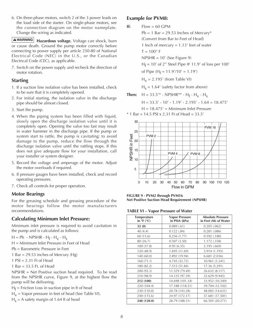
H = Pb - NPSHR - Hf - Hv - HsH = Minimum Inlet Pressure in Feet of HeadPb = Barometric Pressure in Feet1 Bar = 29.53 inches of Mercury (Hg)1 PSI = 2.31 Ft of Head1 Bar = 33.5 Ft. of HeadNPSHR = Net Positive suction head required. To be readfrom the NPSHR curve, Figure 9, at the highest flow thepump will be delivering.Hf = Friction Loss in suction pipe in ft of headHv = Vapor pressure in feet of head (See Table VI).Hs = A safety margin of 1.64 ft of head
Example for PVM8:
If: Flow = 60 GPM
Pb = 1 Bar = 29.53 Inches of Mercury*(Convert from Bar to Feet of Head)
1 Inch of mercury = 1.13’ feet of water
T = 100° F
NPSHR = 10’ (See Figure 9)
Hf = 10’ of 2” Steel Pipe @ 11.9’ of loss per 100’
of Pipe (Hf = 11.9’/10’ = 1.19’)
Hv = 2.195’ (from Table VI)
Hs = 1.64’ (safety factor from above)
Then: H = 33.5’* - NPSHR** - Hf - Hv - Hs
H = 33.5’ - 10’ - 1.19’ - 2.195’ - 1.64 = 18.475’
H = 18.475’ = Minimum Inlet Pressure* 1 Bar = 14.5 PSI x 2.31 Ft of Head = 33.5’
8
5
10
15
20
30
25
0 10 20 30 40 50 60 70 80 90 100 110 120
NP
SH
R in
Fee
t
Flow in GPM
PVM 16
PVM 8PVM 4
PVM 2
FIGURE 9 - PVM2 through PVM16Net Positive Suction Head Requirement (NPSHR)
Temperature Vapor Pressure Absolute Pressurein °F (°C) in PSIA (kPa) in Feet (M) of Water
32 (0) 0.089 (.61) 0.205 (.062)
40 (4.4) 0.122 (.84) 0.281 (.086)
60 (15.6) 0.256 (1.77) 0.592 (.180)
80 (26.7) 0.507 (3.50) 1.172 (.358)
100 (37.8) 0.95 (6.55) 2.195 (.669)
120 (48.9) 1.695 (11.69) 3.914 (1.193)
140 (60.0) 2.892 (19.94) 6.681 (2.036)
160 (71.1) 4.745 (32.72) 10.961 (3.341)
180 (82.2) 7.515 (51.84) 17.36 (5.291)
200 (93.3) 11.529 (79.49) 26.632 (8.117)
210 (98.9) 14.125 (97.39) 32.629 (9.945)
212 (100) 14.698 (101.34) 33.952 (10.349)
220 (104.4) 17.188 (118.51) 39.704 (12.102)
230 (110.0) 20.78 (143.28) 48.002 (14.631)
240 (115.6) 24.97 (172.17) 57.681 (17.581)
248 (120.0) 28.79 (188.51) 66.505 (20.271)
TABLE VI – Vapor Pressure of Water
MAINTENANCEMotor Replacement For Key Numbers, refer to the Exploded View, Figure 14,Page 14 for PVM2 and PVM4 Series Models, Figure 16,Page 16 for PVMI/X2 and PVMI/X4 Models, Figure 15, Page15 for PVM8 and PVM16 Series Models, and Figure 17,Page 17 for PVMI/X8 and PVMI/X16 Series Models.
Hazardous voltage. Disconnect all power tothe pump before servicing or working on pump. Make surethat power is locked out and that pump cannot beaccidentally started.
1. Disconnect the power to the pump motor.
2. Close the nearest suction and discharge valves.
3. Remove the coupling guards (Key No. 4) by pryingthem loose with a screw driver.
4. Remove the socket head screws (Key No. 3) and thecoupling halves (Key No. 2) from the shaft (Key No.16A). For additional reference, see Figure 12, Page 10.
NOTICE: Socket head screws are metric. See Table VIIIon Page 12 for specific metric driver sizes.
5. Remove the shaft pin (Key No. 5).
6. Remove the capscrews (Key No. 12), flatwashers (KeyNo.10), and lockwashers (Key No.11) that hold themotor (Key No. 1) and the motor bracket (Key No. 7)together.
7. Pull the old motor up and off of the motor bracket.NOTICE: Note the location of the conduit box on themotor.
8. Thoroughly clean the surfaces of the mounting flangeson the new motor and the pump end.
9. Install the new motor on the pump with the conduitbox in the desired position.
10. Lubricate the capscrews (Key No. 12) with oil.
11. Reinstall the lockwashers, flatwashers, and capscrewsthat hold the motor and the motor bracket together,then tighten evenly and diagonally. See Table VIII,Page 12 for torque specifications.
12. Reinstall the shaft pin (Key No. 5) in the shaft.
13. Reinstall the coupling halves (Key No. 2) on the pumpand motor shaft. Make sure to engage the shaft pin (KeyNo. 5).
NOTICE: Be sure coupling surfaces are thoroughlyclean prior to assembly.
14. Snug up the socket head screws (Key No. 3) until thecoupling begins to bind and then loosen 1/2 turn.
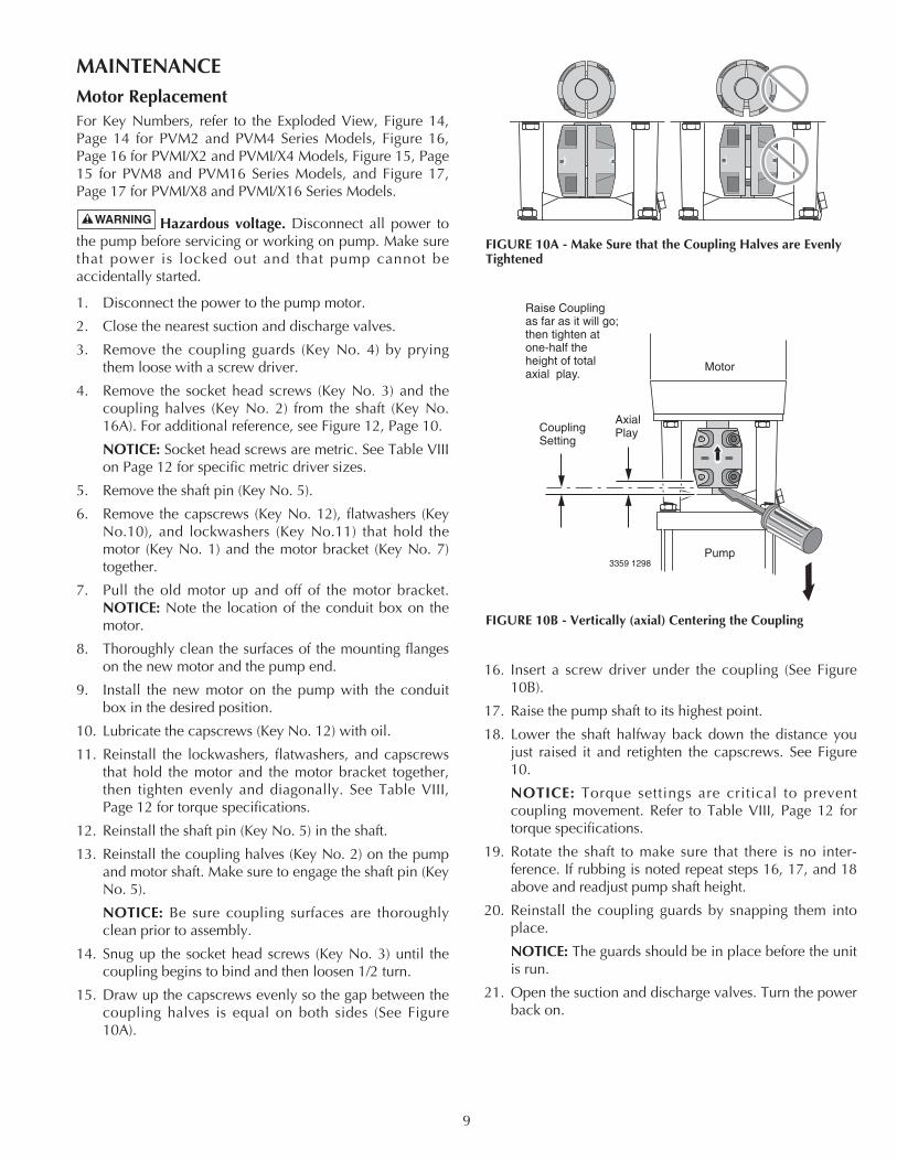
15. Draw up the capscrews evenly so the gap between thecoupling halves is equal on both sides (See Figure10A).
16. Insert a screw driver under the coupling (See Figure10B).
17. Raise the pump shaft to its highest point.
18. Lower the shaft halfway back down the distance youjust raised it and retighten the capscrews. See Figure10.
NOTICE: Torque settings are critical to preventcoupling movement. Refer to Table VIII, Page 12 fortorque specifications.
19. Rotate the shaft to make sure that there is no inter -ference. If rubbing is noted repeat steps 16, 17, and 18above and readjust pump shaft height.
20. Reinstall the coupling guards by snapping them intoplace.
NOTICE: The guards should be in place before the unitis run.
21. Open the suction and discharge valves. Turn the powerback on.
9
FIGURE 10A - Make Sure that the Coupling Halves are EvenlyTightened
Motor
Pump3359 1298
Raise Couplingas far as it will go;then tighten atone-half the height of total axial play.
AxialPlayCoupling
Setting
FIGURE 10B - Vertically (axial) Centering the Coupling
Replacing Pump StackFor Key Numbers, refer to the Exploded View, Figure 14 onPage 14, for the PVM2 and PVM4 Series Models and Figure15 on Page 15 for PVM8 and PVM16 Series Models.
Hazardous pressure. Do not run pump withdischarge valve closed; the water in the pump may boil,causing risk of explosion and steam burns to anyonenearby.
1. Follow steps 1-8 under “Motor Replacement” sectionon Page 9; then proceed with step 2 below.
2. Remove the four staybolt nuts, flatwashers, andlockwashers (Key Nos. 8, 9A, and 9B) from thestaybolts (Key No. 19).
NOTICE: It is not necessary to remove the stayboltswhen replacing the stack.
3. Lift the motor bracket (Key No. 7) off of the pumpbody.
NOTICE: Note the position of the priming plug. Thepriming plug must be returned to its original positionduring reassembly.
4. Remove and discard upper sleeve gasket (Key No. 17).
5. Clean gasket seat.
6. Remove and replace round spring ring (PVM2 andPVM4) or stack spring (PVM8 and PVM16) (Key No.13).
7. Pull the old stack (16A through 16L) out of the stainlesssteel sleeve (Key No. 18) by pulling straight up on thepump shaft (Key No. 16A).
8. Remove the stainless steel sleeve (Key No. 18).
9. Remove and discard the bottom sleeve gasket (Key No.17).
10. Clean the gasket seat.
11. Remove and discard the O-Ring (Key No. 21A) fromthe suction/discharge (Key No. 21 PVM2 and PVM4only).
12. Cast Iron Models Only: Clean the O-Ring seat andinstall a new O-Ring (Key No. 21A).
13. Install a new lower sleeve gasket.
14. Install the new stack without the stainless steel sleeve.
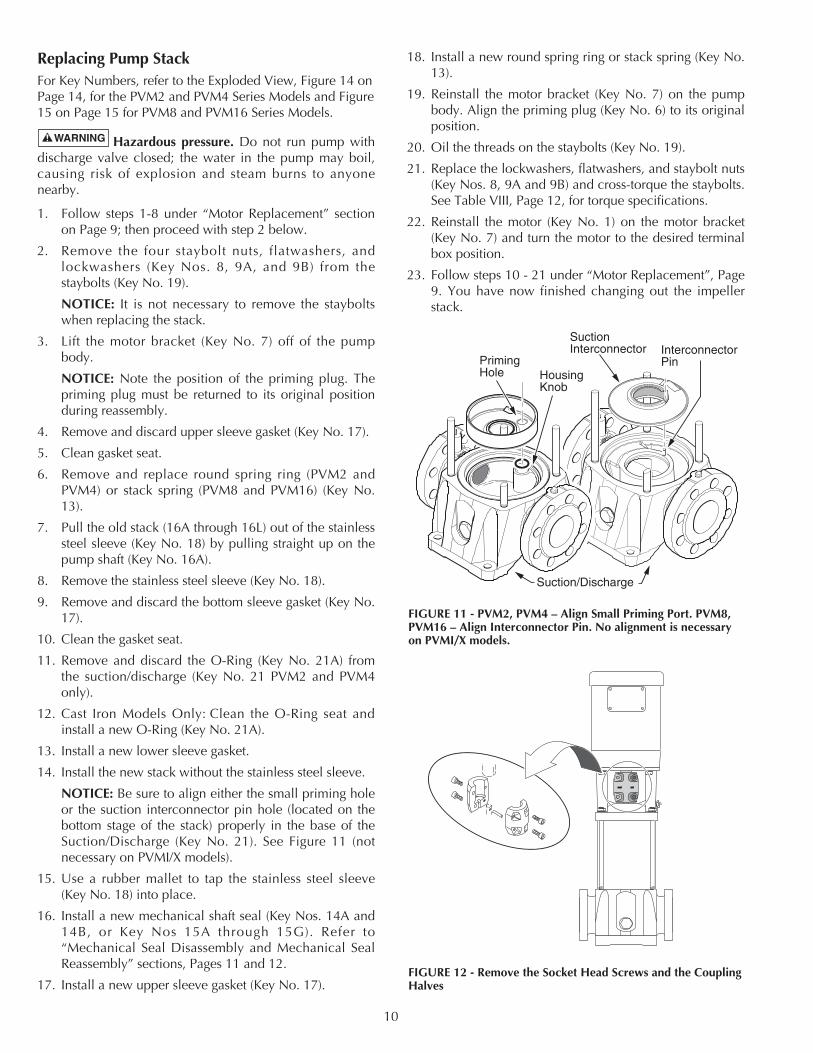
NOTICE: Be sure to align either the small priming holeor the suction interconnector pin hole (located on thebottom stage of the stack) properly in the base of theSuction/Discharge (Key No. 21). See Figure 11 (notnecessary on PVMI/X models).
15. Use a rubber mallet to tap the stainless steel sleeve(Key No. 18) into place.
16. Install a new mechanical shaft seal (Key Nos. 14A and14B, or Key Nos 15A through 15G). Refer to“Mechanical Seal Disassembly and Mechanical SealReassembly” sections, Pages 11 and 12.
17. Install a new upper sleeve gasket (Key No. 17).
18. Install a new round spring ring or stack spring (Key No.13).
19. Reinstall the motor bracket (Key No. 7) on the pumpbody. Align the priming plug (Key No. 6) to its originalposition.
20. Oil the threads on the staybolts (Key No. 19).
21. Replace the lockwashers, flatwashers, and staybolt nuts(Key Nos. 8, 9A and 9B) and cross-torque the staybolts.See Table VIII, Page 12, for torque specifications.
22. Reinstall the motor (Key No. 1) on the motor bracket(Key No. 7) and turn the motor to the desired terminalbox position.
23. Follow steps 10 - 21 under “Motor Replacement”, Page9. You have now finished changing out the impellerstack.
10
FIGURE 12 - Remove the Socket Head Screws and the CouplingHalves
PrimingHole Housing
Knob
SuctionInterconnector Interconnector
Pin
Suction/Discharge
FIGURE 11 - PVM2, PVM4 – Align Small Priming Port. PVM8,PVM16 – Align Interconnector Pin. No alignment is necessaryon PVMI/X models.
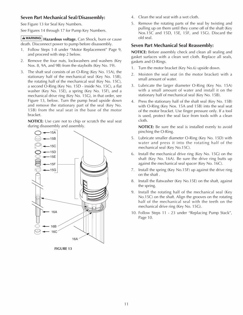
Seven Part Mechanical Seal/Disassembly:See Figure 13 for Seal Key Numbers.
See Figures 14 through 17 for Pump Key Numbers.
Hazardous voltage. Can Shock, burn or causedeath. Disconnect power to pump before disassembly.1. Follow Steps 1-8 under “Motor Replacement” Page 9,
and proceed with step 2 below.
2. Remove the four nuts, lockwashers and washers (KeyNos. 8, 9A, and 9B) from the staybolts (Key No. 19).
3. The shaft seal consists of an O-Ring (Key No. 15A), thestationary half of the mechanical seal (Key No. 15B),the rotating half of the mechanical seal (Key No. 15C),a second O-Ring (Key No. 15D - inside No. 15C), a flatwasher (Key No. 15E), a spring (Key No. 15F), and amechanical drive ring (Key No. 15G), in that order, seeFigure 13, below. Turn the pump head upside downand remove the stationary part of the seal (Key No.15B) from the seal seat in the base of the motorbracket.
NOTICE: Use care not to chip or scratch the seal seatduring disassembly and assembly.
4. Clean the seal seat with a wet cloth.
5. Remove the rotating parts of the seal by twisting andpulling up on them until they come off of the shaft (KeyNos.15C and 15D, 15E, 15F, and 15G). Discard theold seal.
Seven Part Mechanical Seal Reassembly:NOTICE: Before assembly check and clean all sealing andgasket surfaces with a clean wet cloth. Replace all seals,gaskets and O-Rings.
1. Turn the motor bracket (Key No.6) upside down.
2. Moisten the seal seat (in the motor bracket) with asmall amount of water.
3. Lubricate the larger diameter O-Ring (Key No. 15A)with a small amount of water and install it on thestationary half of mechanical seal (Key No. 15B).
4. Press the stationary half of the shaft seal (Key No. 15B)with O-Ring (Key Nos. 15A and 15B) into the seal seatof the motor bracket. Use finger pressure only. If a toolis used, protect the seal face from tools with a cleancloth.
NOTICE: Be sure the seal is installed evenly to avoidpinching the O-Ring.
5. Lubricate smaller diameter O-Ring (Key No. 15D) withwater and press it into the rotating half of themechanical seal (Key No.15C).
6. Install the mechanical drive ring (Key No. 15G) on theshaft (Key No. 16A). Be sure the drive ring butts upagainst the mechanical seal spacer (Key No. 16C).
7. Install the spring (Key No.15F) up against the drive ringon the shaft .
8. Install the flatwasher (Key No.15E) on the shaft, againstthe spring.
9. Install the rotating half of the mechanical seal (KeyNo.15C) on the shaft. Align the grooves on the rotatinghalf of the mechanical seal with the teeth on themechanical drive ring (Key No. 15G).
10. Follow Steps 11 - 23 under “Replacing Pump Stack”,Page 10.
11
15A
15B
15C
15D
15E
15F
15G
16A
16B
16C
16A
FIGURE 13
12
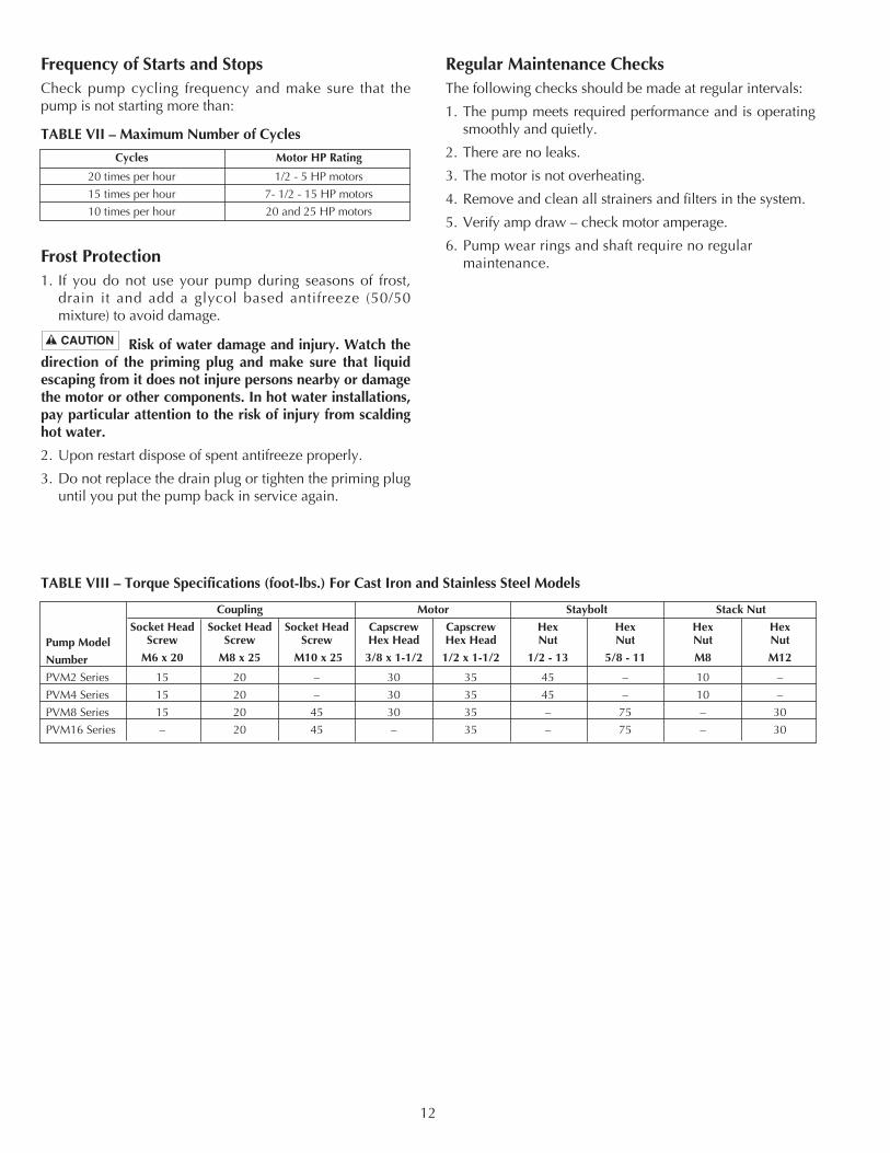
Frequency of Starts and StopsCheck pump cycling frequency and make sure that thepump is not starting more than:
Frost Protection1. If you do not use your pump during seasons of frost,
drain it and add a glycol based antifreeze (50/50mixture) to avoid damage.
Risk of water damage and injury. Watch thedirection of the priming plug and make sure that liquidescaping from it does not injure persons nearby or damagethe motor or other components. In hot water installations,pay particular attention to the risk of injury from scaldinghot water.
2. Upon restart dispose of spent antifreeze properly.
3. Do not replace the drain plug or tighten the priming pluguntil you put the pump back in service again.
Regular Maintenance ChecksThe following checks should be made at regular intervals:
1. The pump meets required performance and is operatingsmoothly and quietly.
2. There are no leaks.
3. The motor is not overheating.
4. Remove and clean all strainers and filters in the system.
5. Verify amp draw – check motor amperage.
6. Pump wear rings and shaft require no regularmaintenance.
Coupling Motor Staybolt Stack Nut
Socket Head Socket Head Socket Head Capscrew Capscrew Hex Hex Hex HexPump Model Screw Screw Screw Hex Head Hex Head Nut Nut Nut Nut
Number M6 x 20 M8 x 25 M10 x 25 3/8 x 1-1/2 1/2 x 1-1/2 1/2 - 13 5/8 - 11 M8 M12
PVM2 Series 15 20 – 30 35 45 – 10 –
PVM4 Series 15 20 – 30 35 45 – 10 –
PVM8 Series 15 20 45 30 35 – 75 – 30
PVM16 Series – 20 45 – 35 – 75 – 30
TABLE VIII – Torque Specifications (foot-lbs.) For Cast Iron and Stainless Steel Models
Cycles Motor HP Rating
20 times per hour 1/2 - 5 HP motors
15 times per hour 7- 1/2 - 15 HP motors
10 times per hour 20 and 25 HP motors
TABLE VII – Maximum Number of Cycles
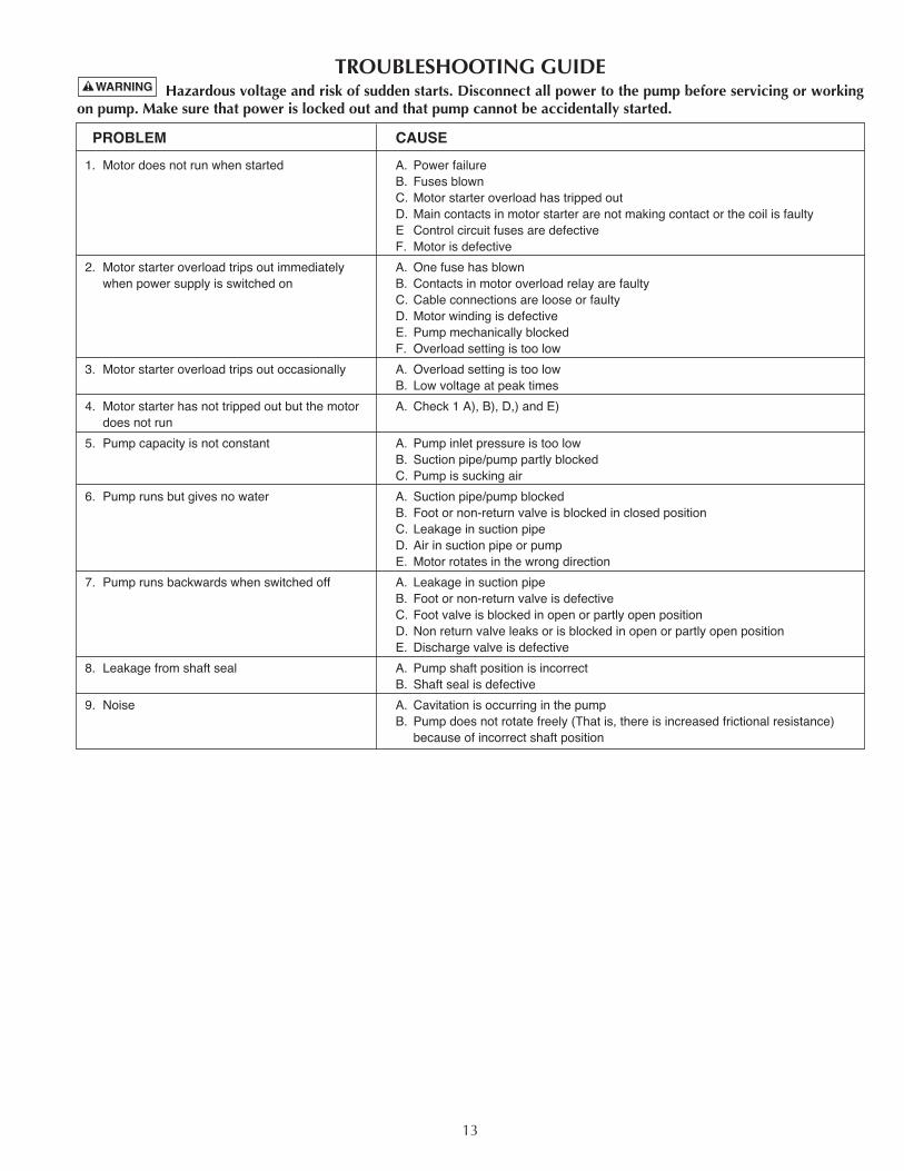
TROUBLESHOOTING GUIDEHazardous voltage and risk of sudden starts. Disconnect all power to the pump before servicing or working
on pump. Make sure that power is locked out and that pump cannot be accidentally started.
PROBLEM CAUSE
1. Motor does not run when started A. Power failureB. Fuses blownC. Motor starter overload has tripped outD. Main contacts in motor starter are not making contact or the coil is faultyE Control circuit fuses are defectiveF. Motor is defective
2. Motor starter overload trips out immediately A. One fuse has blownwhen power supply is switched on B. Contacts in motor overload relay are faulty
C. Cable connections are loose or faultyD. Motor winding is defectiveE. Pump mechanically blockedF. Overload setting is too low
3. Motor starter overload trips out occasionally A. Overload setting is too lowB. Low voltage at peak times
4. Motor starter has not tripped out but the motor A. Check 1 A), B), D,) and E)does not run
5. Pump capacity is not constant A. Pump inlet pressure is too lowB. Suction pipe/pump partly blocked C. Pump is sucking air
6. Pump runs but gives no water A. Suction pipe/pump blockedB. Foot or non-return valve is blocked in closed positionC. Leakage in suction pipeD. Air in suction pipe or pumpE. Motor rotates in the wrong direction
7. Pump runs backwards when switched off A. Leakage in suction pipeB. Foot or non-return valve is defectiveC. Foot valve is blocked in open or partly open positionD. Non return valve leaks or is blocked in open or partly open positionE. Discharge valve is defective
8. Leakage from shaft seal A. Pump shaft position is incorrectB. Shaft seal is defective
9. Noise A. Cavitation is occurring in the pumpB. Pump does not rotate freely (That is, there is increased frictional resistance)
because of incorrect shaft position
13
14
2
5
6
15A15B
15C15D15E15F15G
16A
16B
32
3
4
4
11
10
12
13
14
16C
16D
16E
16F16G
16F16G
16F16G
16F
16F
16G
18
19
1721A20
20
21
17
16H
16E
16I
16E 16J
16L16K
7
89
22232425
3362 0199
1
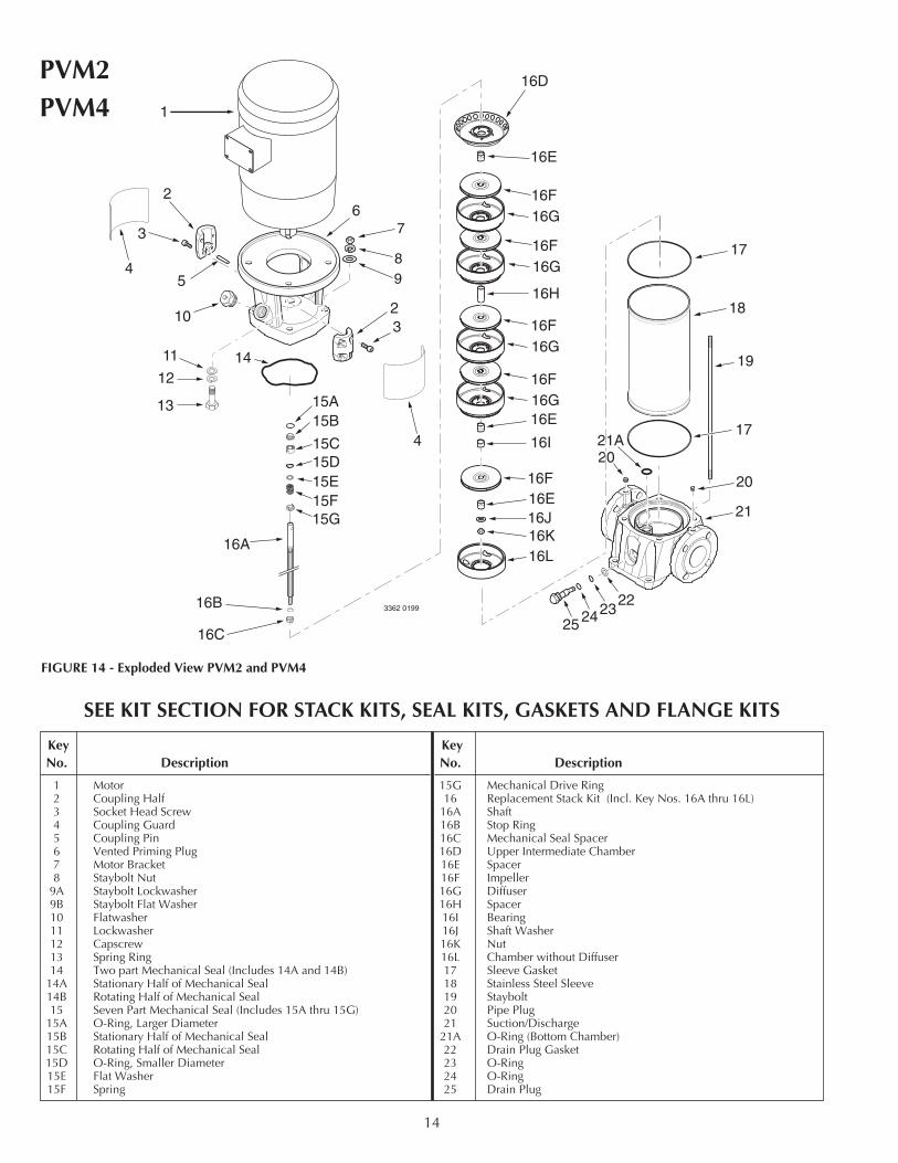
FIGURE 14 - Exploded View PVM2 and PVM4
KeyNo. Description
1 Motor2 Coupling Half3 Socket Head Screw4 Coupling Guard5 Coupling Pin6 Vented Priming Plug7 Motor Bracket8 Staybolt Nut
9A Staybolt Lockwasher9B Staybolt Flat Washer10 Flatwasher11 Lockwasher12 Capscrew13 Spring Ring14 Two part Mechanical Seal (Includes 14A and 14B)
14A Stationary Half of Mechanical Seal14B Rotating Half of Mechanical Seal15 Seven Part Mechanical Seal (Includes 15A thru 15G)
15A O-Ring, Larger Diameter15B Stationary Half of Mechanical Seal15C Rotating Half of Mechanical Seal15D O-Ring, Smaller Diameter15E Flat Washer15F Spring
KeyNo. Description
15G Mechanical Drive Ring16 Replacement Stack Kit (Incl. Key Nos. 16A thru 16L)
16A Shaft16B Stop Ring16C Mechanical Seal Spacer16D Upper Intermediate Chamber16E Spacer16F Impeller16G Diffuser16H Spacer16I Bearing16J Shaft Washer16K Nut16L Chamber without Diffuser17 Sleeve Gasket18 Stainless Steel Sleeve19 Staybolt20 Pipe Plug21 Suction/Discharge
21A O-Ring (Bottom Chamber)22 Drain Plug Gasket23 O-Ring24 O-Ring25 Drain Plug
SEE KIT SECTION FOR STACK KITS, SEAL KITS, GASKETS AND FLANGE KITS
PVM2PVM4
15
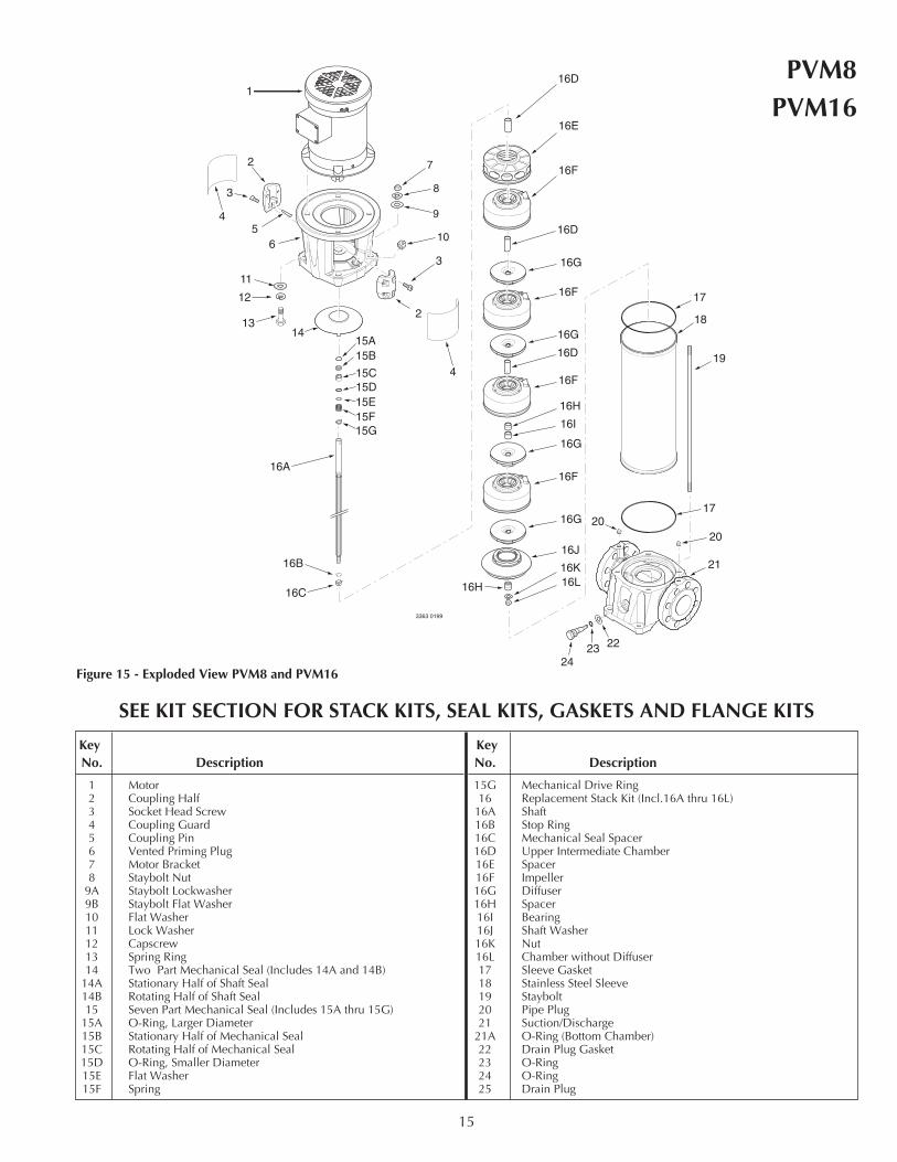
SEE KIT SECTION FOR STACK KITS, SEAL KITS, GASKETS AND FLANGE KITS
1
2
3
56
13
11
12
14
2
3
16A
16B
16C
16D
16D
16D
16E
16F
16F
16F
16F
16H
16H
16J
16K16L
17
19
21
2020
17
18
16I
16G
16G
16G
16G
7
8
9
10
222324
3363 0199
15A15B
15C15D15E15F15G
4
4
Figure 15 - Exploded View PVM8 and PVM16
KeyNo. Description
1 Motor2 Coupling Half3 Socket Head Screw4 Coupling Guard5 Coupling Pin6 Vented Priming Plug7 Motor Bracket8 Staybolt Nut
9A Staybolt Lockwasher9B Staybolt Flat Washer10 Flat Washer11 Lock Washer12 Capscrew13 Spring Ring14 Two Part Mechanical Seal (Includes 14A and 14B)
14A Stationary Half of Shaft Seal14B Rotating Half of Shaft Seal15 Seven Part Mechanical Seal (Includes 15A thru 15G)
15A O-Ring, Larger Diameter15B Stationary Half of Mechanical Seal15C Rotating Half of Mechanical Seal15D O-Ring, Smaller Diameter15E Flat Washer15F Spring
KeyNo. Description
15G Mechanical Drive Ring16 Replacement Stack Kit (Incl.16A thru 16L)
16A Shaft16B Stop Ring16C Mechanical Seal Spacer16D Upper Intermediate Chamber16E Spacer16F Impeller 16G Diffuser16H Spacer16I Bearing16J Shaft Washer16K Nut16L Chamber without Diffuser 17 Sleeve Gasket18 Stainless Steel Sleeve19 Staybolt20 Pipe Plug21 Suction/Discharge
21A O-Ring (Bottom Chamber)22 Drain Plug Gasket23 O-Ring24 O-Ring25 Drain Plug
PVM8PVM16
16
2
5 10
15A15B
15C15D15E15F15G
16A
16B
32
3
4
4
11
12
13
14
16C
16D
16E
16F16G
16F16G
16F16G
16F
16F
16G
18
19
17
21A
21C
17
16H
16E
16I
16E 16J
16L16K
6
7
8
9
4177 0502
1
222321B
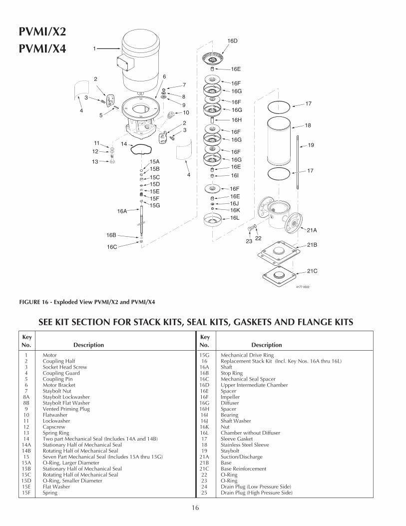
FIGURE 16 - Exploded View PVMI/X2 and PVMI/X4
KeyNo. Description
1 Motor2 Coupling Half3 Socket Head Screw4 Coupling Guard5 Coupling Pin6 Motor Bracket7 Staybolt Nut
8A Staybolt Lockwasher8B Staybolt Flat Washer9 Vented Priming Plug10 Flatwasher11 Lockwasher12 Capscrew13 Spring Ring14 Two part Mechanical Seal (Includes 14A and 14B)
14A Stationary Half of Mechanical Seal14B Rotating Half of Mechanical Seal15 Seven Part Mechanical Seal (Includes 15A thru 15G)
15A O-Ring, Larger Diameter15B Stationary Half of Mechanical Seal15C Rotating Half of Mechanical Seal15D O-Ring, Smaller Diameter15E Flat Washer15F Spring
KeyNo. Description
15G Mechanical Drive Ring16 Replacement Stack Kit (Incl. Key Nos. 16A thru 16L)
16A Shaft16B Stop Ring16C Mechanical Seal Spacer16D Upper Intermediate Chamber16E Spacer16F Impeller16G Diffuser16H Spacer16I Bearing16J Shaft Washer16K Nut16L Chamber without Diffuser17 Sleeve Gasket18 Stainless Steel Sleeve19 Staybolt
21A Suction/Discharge21B Base21C Base Reinforcement22 O-Ring23 O-Ring24 Drain Plug (Low Pressure Side)25 Drain Plug (High Pressure Side)
SEE KIT SECTION FOR STACK KITS, SEAL KITS, GASKETS AND FLANGE KITS
PVMI/X2PVMI/X4
17
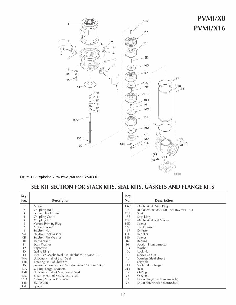
SEE KIT SECTION FOR STACK KITS, SEAL KITS, GASKETS AND FLANGE KITS
1
2
3
5
7
13
11
12
14
2
3
16A
16B
16C
16D
16D
16D
16E
16F
16F
16F
16F
16H
16H
16J
16K16L
17
19
21A
17
18
16I
16G
16G
16G
16G
8
9
10
6
4178 0502
4
4
21B2223
22 23
15B
15C15D15E15F15G
Figure 17 - Exploded View PVMI/X8 and PVMI/X16
KeyNo. Description
1 Motor2 Coupling Half3 Socket Head Screw4 Coupling Guard5 Coupling Pin6 Vented Priming Plug7 Motor Bracket8 Staybolt Nut
9A Staybolt Lockwasher9B Staybolt Flat Washer10 Flat Washer11 Lock Washer12 Capscrew13 Spring Ring14 Two Part Mechanical Seal (Includes 14A and 14B)
14A Stationary Half of Shaft Seal14B Rotating Half of Shaft Seal15 Seven Part Mechanical Seal (Includes 15A thru 15G)
15A O-Ring, Larger Diameter15B Stationary Half of Mechanical Seal15C Rotating Half of Mechanical Seal15D O-Ring, Smaller Diameter15E Flat Washer15F Spring
KeyNo. Description
15G Mechanical Drive Ring16 Replacement Stack Kit (Incl.16A thru 16L)
16A Shaft16B Stop Ring16C Mechanical Seal Spacer16D Spacer16E Top Diffuser16F Diffuser 16G Impeller16H Spacer16I Bearing16J Suction Interconnector16K Washer16L Lock Nut 17 Sleeve Gasket18 Stainless Steel Sleeve19 Staybolt
21A Suction/Discharge21B Base22 O-Ring23 O-Ring24 Drain Plug (Low Pressure Side)25 Drain Plug (High Pressure Side)
PVMI/X8PVMI/X16

18

19

20
Sec
t.6-I
tem
PV
M2-
16