Embed Size (px)
Citation preview

Catalog No.: 2100.50VEffective: 04-01-04Replaces: 01-01-03
P/N 240488
THIS MANUAL SHOULD BE MAINTAINED IN LEGIBLE CONDI-TION AND KEPT ADJACENT TO THE BOILER OR IN A SAFEPLACE FOR FUTURE REFERENCE.
INSTALLATIONAND OPERATINGINSTRUCTIONSRaythermTM
Type H
RESIDENTIAL BOILERS
Models0030B, 0042B, 0066B,0090B0135B, 0180B
FOR YOUR SAFETYDo not store or use gasoline or other flammable vapors and liquids or other combustible materialsin the vicinity of this or any other appliance. To do so may result in an explosion or fire.
WARNING: Improper installation, adjustment, alteration, service or maintenance can causeproperty damage, personal injury or loss of life. Refer to the user's information manual providedwith this boiler. Installation and service must be performed by a qualified installer, service agencyor the gas supplier.
FOR YOUR SAFETYWHAT TO DO IF YOU SMELL GAS*Do not try to light any appliance.*Do not touch any electrical switch; do not use any phone in your building.*Immediately call your gas supplier from a neighbor's phone. Follow the gas supplier's instructions.*If you cannot reach your gas supplier, call the fire department.

CALIFORNIA PROPOSITION 65 WARNING: This product contains chemicals known to the State of California tocause cancer, birth defects or other reproductive harm.
These instructions are provided to assure the proper installation and operation of Raypak boilers. Should questionsarise regarding the specifications, installation, operation or servicing of these boilers, we suggest that the local Salesrepresentative or the factory be consulted.
2
RECEIVING EQUIPMENT................................................................................. 3
GENERAL SPECIFICATIONS........................................................................... 3
INSTALLATION PROCEDURES........................................................................ 4Code Requirements..................................................................................... 4 Mounting Base...........................................................................................4ClearanceRequirments.................................................................................4Combustion/Ventilation Air........................................................................... 4Venting Connections................................................................................... 5Vent Damper Installation.............................................................................. 7Gas Supply Connections............................................................................. 11Water Connections & System Piping............................................................ 11Piping Diagrams..........................................................................................12Electrical Wiring..........................................................................................15Wiring Diagrams......................................................................................... 16
SERVICING PROCECURES.............................................................................. 23General Locations of Controls.......................................................................23Sequence of Operation................................................................................ 23Start-Up Procedures.................................................................................... 24Shut-Down Procedure.................................................................................. 26Safe Shutdown Test.................................................................................... 28Inspection Procedures................................................................................. 28Repair Procedures.......................................................................................29
TROUBLE SHOOTING GUIDE........................................................................... 31Adjustments/Replacements of Components...................................................33
REPLACEMENT PARTS LIST........................................................................... 34
Contents
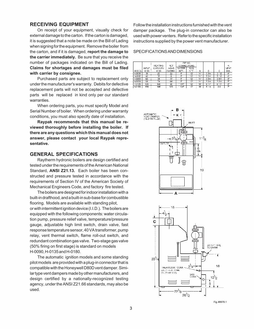
Follow the installation instructions furnished with the ventdamper package. The plug-in connector can also beused with power venters. Refer to the specific installationinstructions supplied by the power vent manufacturer.
SPECIFICATIONS AND DIMENSIONS
3Fig. #8978.1
RECEIVING EQUIPMENTOn receipt of your equipment, visually check for
external damage to the carton. If the carton is damaged,it is suggested that a note be made on the Bill of Ladingwhen signing for the equipment. Remove the boiler fromthe carton, and if it is damaged, report the damage tothe carrier immediately. Be sure that you receive thenumber of packages indicated on the Bill of Lading.Claims for shortages and damages must be filedwith carrier by consignee.
Purchased parts are subject to replacement onlyunder the manufacturer's warranty. Debits for defectivereplacement parts will not be accepted and defectiveparts will be replaced in kind only per our standardwarranties.
When ordering parts, you must specify Model andSerial Number of boiler. When ordering under warrantyconditions, you must also specify date of installation.
Raypak recommends that this manual be re-viewed thoroughly before installing the boiler. Ifthere are any questions which this manual does notanswer, please contact your local Raypak repre-sentative.
GENERAL SPECIFICATIONSRaytherm hydronic boilers are design certified and
tested under the requirements of the American NationalStandard, ANSI Z21.13. Each boiler has been con-structed and pressure tested in accordance with therequirements of Section IV of the American Society ofMechanical Engineers Code, and factory fire tested.
The boilers are designed for indoor installation with abuilt-in drafthood, and a built-in sub-base for combustibleflooring. Models are available with standing pilot,or with intermittent ignition device (I.I.D.). The boilers areequipped with the following components: water circula-tion pump, pressure relief valve, temperature/pressuregauge, adjustable high limit switch, drain valve, fastresponse temperature sensor, 40 VA transformer, pumprelay, vent thermal switch, flame roll-out switch, andredundant combination gas valve. Two-stage gas valve(50% firing on first stage) is standard on modelsH-0090, H-0135 and H-0180.
The automatic ignition models and some standingpilot models are provided with a plug-in connector that iscompatible with the Honeywell D80D vent damper. Simi-lar type vent dampers made by other manufacturers, anddesign certified by a nationally-recognized testingagency, under the ANSI Z21.66 standards, may also beused.

3. INSTALLATION PROCEDURES
CODE REQUIREMENTSInstallation must be in accordance with local
codes, or, in the absence of local codes, with the latesteditions of the National Fuel Gas Code, ANSI Z223.1,and the National Electrical Code, ANSI/NFPA 70. InCanada, installations must conform with the currentCAN/CGA B149.1 or .2 and the Canadian ElectricalCode Part 1 CSA C22.2 No.1. Where required by theauthority having jurisdiction, the installation must con-form to American Society of Mechanical EngineersSafety Code for Controls and Safety Devices for Auto-matically Fired Boilers, No. CSD-1.
MOUNTING BASEBoiler should be mounted on a level surface. Each
boiler is designed with a built-in sub-base approved formounting the boiler on combustible flooring. Boilermust NOT be installed on carpet flooring.
NOTE: The boiler should be located in an area wherewater leakage will not result in damage to the areaadjacent to the appliance or to the structure. Whensuch locations cannot be avoided, it is recommendedthat a suitable drain pan, adequately drained, be in-stalled under the appliance. The pan must not restrictair flow.
In addition, the boiler shall be installed such thatthe gas ignition system components are protected fromwater (dripping, spraying, rain, etc.) during applianceoperation and service (circulator replacement, controlreplacement, etc.)
4
CLEARANCE REQUIREMENTS1) Minimum Clearances From Combustible Materials
Model Floor Front Back Right Left Top FlueNo. Vent00300042 Comb. 4" 6" 6" 6" 16" 6"006600900135 Comb. Alcove 6" 6" 6" 16" 6"0180
2) A front clearance of at least 24" is recommended foradequate service of burner-tray and controls.
3) Except for carpeted flooring, boilers are certified forinstallation on combustible floors.
4) For un-insulated hot water pipes, maintain a 2"clearance, or consult local authority having jurisdic-tion.
COMBUSTION/VENTILATION AIR
WARNING: Air supply to the boiler room must not beaffected by mechanical exhaust vents located in otherparts of the house, such as kitchen or bathroom fans,or attic blowers. Mechanical exhaust vents may createa negative pressure condition in the boiler room thatcan become a hazard of asphyxiation, explosion or fire.
CAUTION: Combustion air must not be contaminatedby corrosive chemical fumes which can damage theboiler. Measures must be taken to prevent the entry ofcorrosive chemical fumes to the combustion and ven-tilation air supply. Such chemicals include, but are notlimited to, chlorinated and/or fluorinated hydrocarbonssuch as found in refrigerants, aerosol propellants, dry-cleaning fluids, degreasers, and paint removers. Otherharmful elements may come from bleaches, air fresh-eners, or mastics. Vapors from these types of productscan form corrosive acid compounds when burned in agas flame. The resulting acid condensate can damageor substantially reduce the life of the heater. It may benecessary to provide outside air directly to the heater inorder to avoid this problem.
1) The boiler must be provided with adequate supply ofair for proper combustion and ventilation in accor-dance with Sec. 5.3, of the latest edition of theNational Fuel Gas Code, ANSI Z223.1, or appli-cable provisions of the local building codes.
Fig.# 8196

2) When the boiler is installed in a confined spacesuch as a utility room or closet (Models 0030,0042and 0066 only), where all air is supplied from insidethe building, the boiler room must be provided withtwo openings, each one having a minimum net freearea, in square inches as follows:
Model Sq. In. of Free Area 0030, 0042 & 0066 100
One opening shall be within 12" of the top, and theother opening within 12" of the floor. If additional gasappliances are installed in the same space, the total inputof all gas appliances installed in the same space, mustbe considered in the calculation. Refer to Sec. 5.3.5 of thelatest edition of the National Fuel Gas Code for additionalrequirements.
Fig. #8198.0
NOTE: If louvers, grills or screens are used on theopenings, obtain the net free area requirements fromtheir supplier or manufacturer. If the design free area ofa louver is not known nor available, it shall be assumedthat wood louvers will have 20-25 percent free area andmetal louvers will have 60-75 percent free area as shownin Sec. 5.3.5 National Fuel Gas Code.
3) If the boiler room is located against an outside walland air openings can communicate directly with theoutdoors, the two openings on the outside wall musteach have a net free area as follows:
Model (Sq. In.) Net Free Area 0030 & 0042 12
0066 180090 240135 350180 45
5
Location of the openings is the same as in theprevious case - that is, within 12" of the top, and within 12"of the bottom of the enclosure. If horizontal ducts areused, the area must be doubled and the duct area shallnot be less than the area of the openings they connect,and in no case shall the smallest dimension be less than3".
VENTING CONNECTIONSThese boilers have built-in drafthoods. Vent piping
the same size or larger than the drafthood outlet isrecommended; however, when the total vent height(drafthood outlet to vent terminal) is at least ten (10)feet, the vent pipe size may be reduced by one size onlyas specified in Chapter 10 of the latest edition of theNational Fuel Gas Code, ANSI Z 223.1. As much aspossible, avoid long horizontal runs of vent pipe and toomany elbows. If installation requires horizontal runs, thevent pipe must have a minimum of 1/4 inch per foot riseand should be supported at not less than five footintervals. Maximum vent connector horizontal lengthshall be 1-1/2 feet (18 inches) for each inch of connectordiameter as follows.
Model Vent Connector Max Horizontal Diameter Length - FT
30 & 42 4" 6' 66 & 90 5" 7.5' 135 6" 9' 180 7" 10.5'
Gas vents supported only by the flashing and extend-ing above the roof more than five feet should be securelyguyed or braced to withstand snow and wind loads. Werecommend use of insulated vent pipe spacer through theroofs and walls.
For protection against rain or blockage by snow, thevent pipe must terminate with a listed vent cap whichcomplies with the local codes or, in the absence of suchcodes, to the latest edition of the National Fuel GasCode, ANSI Z 223.1.
The discharge opening must be a minimum of twofeet vertically from the roof surface and at least two (2)feet higher than any part of the building within ten (10)feet. Vent stack shall be at least five (5) feet in verticalheight above the drafthood outlet. The vent cap locationshall have a minimum clearance of four (4) feet horizon-tally from, and in no case above or below, unless a 4-foothorizontal distance is maintained, from electric meters,gas meters regulators and relief equipment.

The weight of the vent stack or chimney must not reston the boiler's drafthood. Support must be provided incompliance with applicable codes. The boiler top anddrafthood must be readily removable for maintenance andinspection. Vent pipe should be adequately supported tomaintain proper clearances from combustible construc-tion.
Type "B" double-wall (or equivalent vent pipe isrecommended. However single-wall metal vent pipe maybe used as specified in the latest edition of the NationalFlue Gas Code ANSI Z 223.1.
6
Fig.# 8191
WARNING: These boilers must not be connected intoany portion of mechanical draft systems operatingunder positive pressure. To do so may cause the flueproducts to be discharged into the living space causingserious health injury.
For connections to gas vents or chimneys, ventinstallations shall be in accordance with Part 7, Ventingof Equipment, of the National Fuel Gas Code, ANSIZ223.1, or applicable provisions of the local buildingcodes.
COMMON VENTSManifolds that connect more than oneboiler to a common chimney must besized to handle the combined load.Consult available guides for propersizing of the manifold and the chimney.At no time should the area be less thanthe area of the largest outlet.
Fig. #9001
Lowest Discharge Opening
Listed Cap
Listed Gas Vent
X
12
Roof Pitch is X/12
H - Minimum Height from Roof to Lowest Discharge Opening
Roof Pitch H (Min. Ft.)Flat to 6/12 1.06/12 to 7/12 1.25
Over 7/12 to 8/12 1.5 Over 8/12 to 9/12 2.0 Over 9/12 to 10/12 2.5 Over 10/12 to 11/12 3.25 Over 11/12 to 12/12 4.0 Over 12/12 to 14/12 5.0 Over 14/12 to 16/12 6.0 Over 16/12 to 18/12 7.0 Over 18/12 to 20/12 7.5 Over 20/12 to 21/12 8.0
7
At the time of removal of an existing boiler, thefollowing steps shall be followed with each applianceremaining connected to the common venting systemplaced in operation, while the other appliances remain-ing connected to the common venting system are not inoperation.
(a) Seal any unused openings in the common ventingsystem.
(b) Visually inspect the venting system for proper sizeand horizontal pitch and make sure there is noblockage or restriction, leakage, corrosion andother deficiencies which could cause an unsafecondition.
(c) Insofar as is practical, close all building doors andwindows and all doors between the space in whichthe appliances remaining connected to the com-mon venting system are located and other spacesof the building. Turn on clothes dryers and anyappliance not connected to the common ventingsystem. Turn on any exhaust fans, such as rangehoods and bathroom exhausts, so they will operateat maximum speed. Do not operate a summerexhaust fan. Close fireplace dampers.
(d) Place in operation the appliance being inspected.Follow the lighting instructions. Adjust thermostatso appliance will operate continuously.
e) Test for spillage at the drafthood relief openingafter 5 minutes of main burner operation. Use theflame of a match or candle, or smoke from acigarette, cigar or pipe to visually check spillage.
(f) After it has been determined that each applianceremaining connected to the common venting sys-tem properly vents when tested as outlined above,return doors, windows, exhaust fans, fireplacedampers and any other gas burning appliance totheir previous conditions of use.
(g) Any improper operation of the common ventingsystem should be corrected so that the installationconforms with the latest edition of the National FuelGas Code, ANSI Z 223.1. When resizing anyportion of the common venting system, the com-mon venting system should be resized to approachthe minimum size as determined using theappropriate tables in Chapter 10 and in Appendix
G of the National Fuel Gas Code, ANSI Z 223.1and CAN/CGA - B149.1 - B149.2.
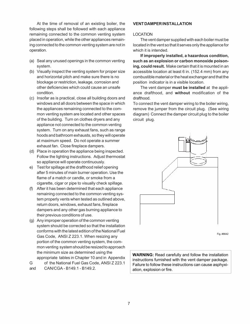
VENT DAMPER INSTALLATION
LOCATIONThe vent damper supplied with each boiler must be
located in the vent so that it serves only the appliance forwhich it is intended.
If improperly installed, a hazardous condition,such as an explosion or carbon monoxide poison-ing, could result. Make certain that it is mounted in anaccessible location at least 6 in. (152.4 mm) from anycombustible material or the heat exchanger and that theposition indicator is in a visible location.
The vent damper must be installed at the appli-ance drafthood, and without modification of thedrafthood.To connect the vent damper wiring to the boiler wiring,remove the jumper from the circuit plug. (See wiringdiagram) Connect the damper circuit plug to the boilercircuit plug.
Fig. #8642
WARNING: Read carefully and follow the installationinstructions furnished with the vent damper package.Failure to follow these instructions can cause asphyxi-ation, explosion or fire.

1K
1K1
1K2
D80MOTOR
N.C.ENDSWITCH
N.O.1K3
C.
4 3 2 1
YE
LL
OW
BL
UE
BL
AC
K
OR
AN
GE
CABLE
8
MOUNTINGOn vertical vents, the vent damper may be mounted with the actuator in any position. On horizontal vents,
do not mount the actuator either directly above or directly below the vent pipe; mount the vent damper actuatorto the side of the vent.
The vent damper is set up for a continuous pilot system. If the vent damper is installed on a system with anIntermittent Pilot or Hot Surface Ignition the energy savings of the vent damper can be improved by plugging the holein the vent damper blade using the knockout plug, Part No. 105612R, provided in the parts envelope.
Hole in Vent Damper Blade Closed Position
Fig. #8994
DO NOT plug the hole if installing the vent damper on a continuous pilot system as this will create ahazardous condition.
Fig. #8183.0
INSTALLING THE VENT DAMPER IN HORIZONTAL& VERTICAL VENT.
Fig. #152323
D80D GENERAL WIRING DIAGRAM
INSTALL THE VENT DAMPER TO SERVICE ONLY THE SINGLE APPLIANCE FOR WHICH IT IS INTENDED.IF IMPROPERLY INSTALLED, A HAZARDOUS CONDITION, SUCH AS AN EXPLOSION OR CARBONMONOXIDE POISONING, COULD RESULT.

SS
R2 SS2 ES
R
SC
R1
M
2 3 41
JUMPER
GV24 VAC
TR
HL
LL1 2
120 VAC 60Hz
TH
1
9
NOTE: To place vent damper in theopen position to allow burneroperation:Turn the power off. Turn the damperblade to fully open position (arrowfacing same direction as vent pipe).Turn power on.
R
24
3 JSS HL
GV
1
ES
R2
SC
M
24 V AC
R 1
SS2
TH
DAMPER POSITIONINDICATOR
DAMPER POSITIONINDICATOR
DAMPER OPEN DAMPER CLOSED
VENT DAMPER OPERATION
For safe, efficient operation, the vent damper and all flue-product-carrying areas of the appliance mustbe checked annually, with particular attention given to deterioration from corrosion or other sources.Check vent damper operation as follows:
1. When the boiler is off, check that the vent damper position indicator points to the closed position, below.
Fig. # 8181.0
VENT DAMPER POSITION INDICATOR
2. Turn the thermostat or controller up to call for heat and check that the vent damper indicator points to theopen position, below.
3. Turn the thermostat or controller down again and check that the vent damper position indicator returns tothe closed position.THE VENT DAMPER MUST BE INSPECTED AT LEAST ONCE A YEAR BY A TRAINED, EXPERIENCED
SERVICE TECHNICIAN. THE NAME OF THE PERSON WHO ORIGINALLY INSTALLED YOUR VENTDAMPER IS SHOWN ON THE INSTALLATION LABEL. DAMPER MUST BE IN OPEN POSITION WHENBOILER MAIN BURNERS ARE OPERATING.
FLAIR DAMPERSYSTEM SCHEMATIC LEGEND LADDER DIAGRAM
M - Damper motor R - Relay ES - End switchSS1 - N/C Safety switchSS2 - N/O Safety switch
contacts TR - Transformer 120/24V HL - High limit GV - 24V gas valve* TH - Thermostat, heating, low voltage J - JumperNote: Circuit shown with damper in closed position, no call for heat.
Fig. #9002 Fig. #9003

CONNECTION DIAGRAM
10
The gas valve is provided with pressure taps tomeasure gas pressure upstream of the gas valve anddownstream which is the same as the manifold pres-sure.
WATER CONNECTIONS & SYSTEM PIPINGThe pipe size for water connections is shown on
page 3. Typical piping systems are shown on pages 12to 14.
The boiler is supplied with a circulator and built inbypass as standard to ensure the required minimumwater flow in the boiler. The bypass on models H-0135and H-0180 is provided with an adjustable valve that isfactory-set in the full open position. The handle is shippedloose. The full open position is appropriate for mostsystems, and ensures adequate flow through the boiler.If system flow is inadequate, (indicated by excessivetemperature drop through the system) the bypass valvecan be throttled slightly. Care must be taken against over-throttling which may lead to inadequate flow through theboiler and boiler harmonics (a humming sound from theheat exchanger). If adequate system flow cannot beobtained without causing harmonics, an additional pumpis required. The factory-mounted circulator will provideadequate water flow for systems designed at a 20°Ftemperature drop, and system pressure drop or head notexceeding that which is shown below.
When the total system head exceeds the availablehead pressures, a primary/secondary pumping systemis recommended.
The minimum boiler operating temperatureshould be 105°F. When operating at low tempera-ture applications, T (temperature rise) must be20°F or less.
Propylene glycol solution is commonly used in theheating system when freeze protection is required. Thiswill affect the system design and pump performance. Asa rule of thumb, 50% solution of propylene glycol willrequire the system flow (GPM) to increase by 14%, andthe system head (Ft/Wtr) by 23% in order to maintain thesame heat transfer load.
11
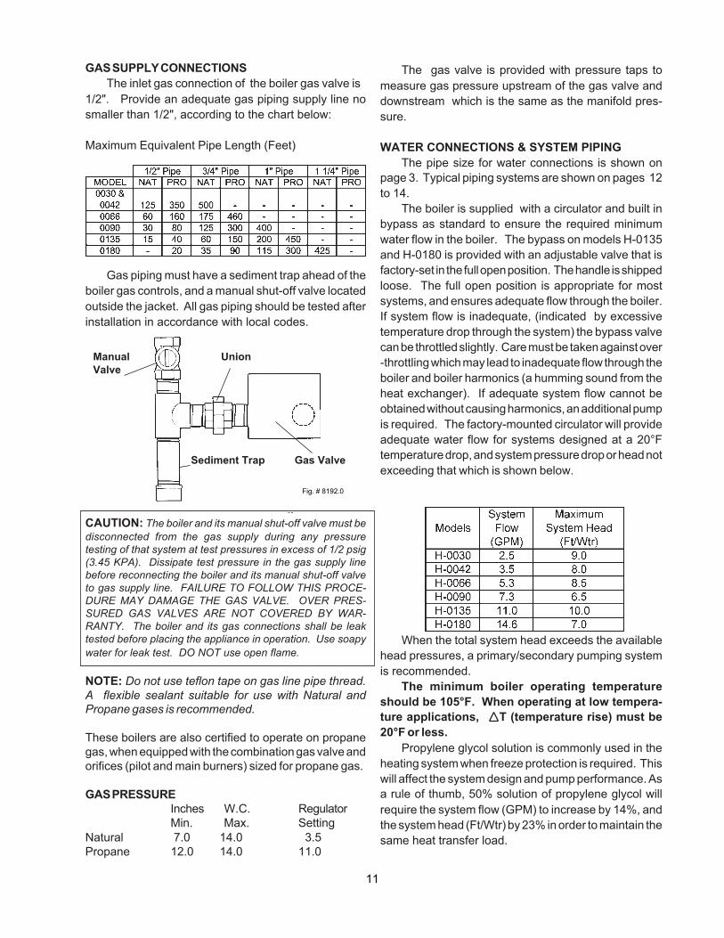
GAS SUPPLY CONNECTIONSThe inlet gas connection of the boiler gas valve is
1/2". Provide an adequate gas piping supply line nosmaller than 1/2", according to the chart below:
Maximum Equivalent Pipe Length (Feet)
Gas piping must have a sediment trap ahead of theboiler gas controls, and a manual shut-off valve locatedoutside the jacket. All gas piping should be tested afterinstallation in accordance with local codes.
CAUTION: The boiler and its manual shut-off valve must bedisconnected from the gas supply during any pressuretesting of that system at test pressures in excess of 1/2 psig(3.45 KPA). Dissipate test pressure in the gas supply linebefore reconnecting the boiler and its manual shut-off valveto gas supply line. FAILURE TO FOLLOW THIS PROCE-DURE MAY DAMAGE THE GAS VALVE. OVER PRES-SURED GAS VALVES ARE NOT COVERED BY WAR-RANTY. The boiler and its gas connections shall be leaktested before placing the appliance in operation. Use soapywater for leak test. DO NOT use open flame.
NOTE: Do not use teflon tape on gas line pipe thread.A flexible sealant suitable for use with Natural andPropane gases is recommended.
These boilers are also certified to operate on propanegas, when equipped with the combination gas valve andorifices (pilot and main burners) sized for propane gas.
GAS PRESSUREInches W.C. RegulatorMin. Max. Setting
Natural 7.0 14.0 3.5Propane 12.0 14.0 11.0
Sediment Trap Gas Valve
Manual UnionValve
Fig. # 8192.0

Systems with multiple zones may require an additional circulator. Consult manufacturer's data for valve pressuredrops. When an indirect water heating system is used, it is recommended that a separate circulator be installedto meet the required flow and pressure drop conditions of the indirect water heater.
We recommend that the make-up water from the cold water line have a check valve, gate valve, and feedwaterregulator set at 12 psig. Install unions and gate or ball valves at inlet and outlet connections at the boiler to facilitateservicing.
The pressure relief valve is mounted on the boiler and must be piped to a drain. We recommend that all highpoints be vented and that purge valves be installed. A boiler installed above radiation level must be provided witha low water cut-off device. See page 22 for wiring hook-up. The boiler, when used in connection with a refrigerationsystem, must be installed so that the chilled medium is piped in parallel with the boiler with appropriate valves toprevent the chilled medium from entering the boiler.
The boiler piping system of a hot water heating boiler, that is connected to heating coils located in air handlingunits where they may be exposed to refrigerated air circulation, must be equipped with flow control valves or otherautomatic means to prevent gravity circulation of the boiler water during the cooling cycle.
A diaphragm expansion tank should be installed in the return line. A typical 8" -diameter expansion tank canbe used on models H-0030, H-0042, and H-0066, and an 11"-diameter expansion tank can be used on models H-0090, H-0135 and H-0180. Consult tank manufacturer for correct sizing.
PIPING DIAGRAMS
12
SINGLE-ZONE PIPING
Fig.# 8997.1
AIRSCOOP
AIRVENT
FEEDVALVE
DIAPHRAGMEXPANSION TANK
HEATING UNITS
COLDWATERINLET
PIPE PRESSURERELIEF VALVE
TO DRAIN

13
ZONE HEATING WITH INDIRECT DOMESTICHOT WATER SUPPLY
Fig.# 8998.1
ZONEVALVES
HEATING UNITS
FEEDVALVE
COLDWATERINLET
CIRCULATOR
PIPE PRESSURERELIEF VALVE
TO DRAIN
DIAPHRAGMEXPANSION
TANK
AIRSCOOP
AIRVENT
HOT WATERSUPPLY
COLDWATERSUPPLY

14
MULTIPLE ZONES WITH CIRCULATORS
MULTIPLE ZONES WITH ZONE VALVES
AIRSCOOP
AIRVENT
12" MAX.
AIRVENT
AIRSCOOP
COLDWATERINLET
FEEDVALVE
PIPE PRESSURERELIEF VALVE
TO DRAIN
DIAPHRAGMEXPANSION
TANK
HEATING UNITS
ZONEVALVES
DIAPHRAGMEXPANSION
TANK
PIPE PRESSURERELIEF VALVE
TO DRAIN
FEEDVALVE
COLDWATERINLET
CIRCULATORS
HEATING UNITS
Fig. #8999.1
Fig. #9000.1

15
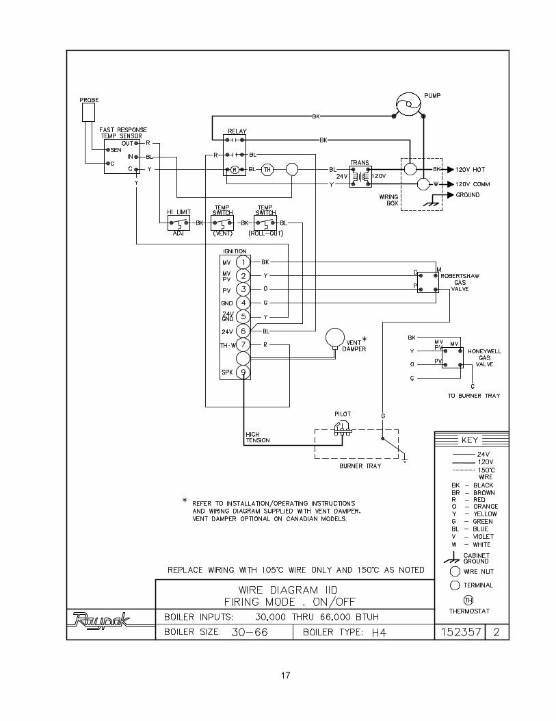
WIRING DIAGRAM KEY
Fig.# 8096.2
The room thermostat should be installed in accordancewith the manufacturer's instructions. The thermostat heatanticipator should be set at 1.0 ampere (automaticignition) and 0.60 ampere (standing pilot) for single- zoneinstallations. For multi-zone applications, the heat antici-pator setting should be based on the ampere load in thethermostat circuit.
NOTE: If it is necessary to replace any of the originalwiring, it must be replaced with 105°C wire or itsequivalent, except 150° C black wire must be replacedwith 150°C wire or its equivalent. See Wiring Diagram Keyfor 150°C wire indication.
ELECTRICAL WIRINGThe electrical power supply requirement for these
boilers is 115 volts, 60 Hz. Field wiring connections andelectrical grounding must comply with the local codes,or in the absence of local codes, with the NationalElectrical Code, ANSI/NFPA 70-1987. Provide a sepa-rate fused circuit from the main electrical panel to theboiler, and a disconnecting means within sight of theboiler.
Remove the control box cover and make the powersupply connections in the field wiring compartment.(See general location of controls drawing on page 23).The pump is supplied and factory-wired to operate withthe boiler. The "TH" wire leads are for the room thermo-stat or zone valve connections.

16
WIRING DIAGRAM KEY
17

18

WIRING DIAGRAM: Single-Zone Taco Valve
WIRING DIAGRAM: Dual-Zone Taco Valve
WIRING DIAGRAM: Dual-Zone Honeywell Valve
NOTE: Maximum three (3) zone valves per one (1) 40 VA transformer.
NOTE: Maximum five (5) zone valves per one (1) 40 VA Transformer.
Fig. # 2230e
Fig. # 2229e
Fig. # 2228e
19

WIRING DIAGRAM: System with (3) Zone Pumps
NOTE: Check VA rating of each relay coil. Total load must not exceed VA rating of transformer.Fig. #2232e
Fig. #2233e
Fig. #2234e
WIRING DIAGRAM: Power Vent System w/ Zone Valve
20

21
WIRING DIAGRAM: Primary/Secondary Pumping SystemHoneywell Zone Valve
Fig. #2223.2e

WIRING DIAGRAM: Standing Pilot With Low Water Cut-off Device
Fig. # 2223.1e
Note: Low water cut-off (LWCO) and system switch supplied by others.
WIRING DIAGRAM: IID Units With Low Water Cut-off Device
Note: Low water cut-off (LWCO) and system switch supplied by others.
22
Fig. # 2357E

4. SERVICING PROCEDURES
GENERAL LOCATION OF CONTROLS
Fast-ResponseTemperatureSensor
CONTROL BOX COMPONENTLOCATIONS MODELS 135 & 180
2-Stage Controller
Relay
Fig.# 8195.1
Ignition Module(Auto Ignition Only)
23
Fig.# 8195.4
SEQUENCE OF OPERATIONINTERMITTENT IGNITION DEVICE (IID)Boilers equipped with the IID system will automatically light the pilot burner first and then the main burner, eachtime there is a call for heat from the room thermostat. Whenever the room thermostat is calling for heat, thecirculator supplied with the boiler, will be energized and should be running. The ignition control module will alsobe energized to initiate the pilot ignition by opening the first main valve (pilot). At the same time, the electronicspark generator in the module produces a high-voltage spark pulse output that lights the pilot burner. If the pilot burnerdoes not light, the module will not energize the second main valve and the burners will not light. Ignition sparkcontinues only until the timed trial for ignition period ends. Then, the module goes into safety shutdown or lockout.Lockout de-energizes the first main valve operator and closes the first main (pilot) valve in the gas control, stoppingpilot gas flow. The ignition control system must be reset by setting the thermostat below room temperature for oneminute or by turning off power to the module for one minute. When the pilot flame is established, flame rectificationcircuit is completed between the sensor and burner ground. The flame sensing circuit in the module detects the flamecurrent, shuts off the spark generator and energizes the second main valve operator which opens the second mainvalve. This allows gas to flow to the burners where it is ignited by the pilot burner flame. When the thermostat issatisfied, the valve operators are de-energized shutting off the pilot and main burners, and also the circulator.
CIRCULATOR
VENT SENSOR
BYPASS VALVE(MODELS 135 & 180 ONLY)
BYPASS LINE
TEMPERATUREAND PRESSURE GAUGE
2-STAGED CONTROLLER(MODEL 90 ONLY)
PRESSURERELIEF VALVE
RELAY
ADJUSTABLEHIGH LIMIT
FIELD WIRINGCOMPARTMENT
FAST RESPONSETEMPERATURE SENSOR
IGNITION MODULE(AUTO IGNITION ONLY)
TRANSFORMER
ROLL-OUT SENSOR
GAS VALVE

24
START-UP PROCEDURES
Lighting the BoilerSafe-lighting and other performance criteria were met
with the gas manifold and control assembly provided onthe boiler when the boiler underwent tests specified inANSI-Z21.13a 1983 Standard.
CAUTION: Propane gas is heavier than air and sinks tothe ground. Exercise extreme care in lighting boiler inconfined areas.
For Standing Pilot ModelsWARNING: If you do not follow these instructionsexactly, a fire or explosion may result causing propertydamage, personal injury or loss of life.
A. This boiler has a pilot which must be lighted byhand. When lighting the pilot, follow these instructionsexactly.
B. BEFORE LIGHTING Smell all around the boilerarea for gas. Be sure to smell next to the floor becausesome gas is heavier than air and will settle on the floor.
WHAT TO DO IF YOU SMELL GAS� Do not try to light any appliance.� Do not touch any electric switch;� Do not use any phone in your building.� Immediately call your gas supplier from a neighbor's phone. Follow the gas supplier's instructions.� If you cannot reach your gas supplier, call the fire department.
C. Use only your hand to push in, move or turn the gascontrol knob or lever. Never use tools. If the knob orlever will not push in, move or turn by hand, don't try torepair it, call a qualified service technician. Force orattempted repair may result in a fire or explosion.
D. Do not use this boiler if any part has been under water.Immediately call a qualified service technician to inspectthe boiler and to replace any part of the control systemand any gas control which has been under water.
Filling the SystemFill system with water. Purge all air from the system
using purge valve sequence. After system is purged ofair, lower system pressure. Open valves for normalsystem operation, fill system through feed pressureregulator to minimum 12 PSI. Manually open air venton the compression tank until water appears, then closevent.
On multiple-zone systems, purge each zone sepa-rately. Isolate the other zones while one zone is beingpurged of air.
Flush system before putting into operation to ensurethat foreign material does not damage pump seals.
Checking the CirculatorBefore lighting the boiler and after system is filled,
make sure that circulator is operating properly. Manualgas valve should be off. By adjusting the wall thermo-stat to the maximum setting, circulator should runimmediately and allow water to flow through the boilerand the entire system.
NOTE: Circulator motor supplied with the boiler doesnot require lubrication.
CAUTION: In case of a prolonged power failure duringfreezing weather conditions, boiler and piping systemmust be drained completely to avoid possible damageto the heating system.

25
10. Turn on all electrical power to the boiler.11. Set the thermostat to the desired setting.
TO TURN OFF GAS TO THE BOILER:(Models 90, 135 & 180)
1. Set the thermostat to the lowest setting.2. Turn off all electrical power to the boiler3. Push in and move gas control lever counter-
clockwise to "OFF" position. Do not force.
FOR AUTOMATIC IGNITION MODELS.
Please read carefully and understand the followingsafety information before operating the boiler.
WARNING: If you do not follow these instructionsexactly, a fire or explosion may result causing propertydamage, personal injury or loss of life.
A. This boiler is equipped with an ignition device whichautomatically lights the pilot. Do not try to light the pilotby hand; or this boiler may not have a pilot and isequipped with a hot surface ignition device which auto-matically lights the burners. Do not try to light theburners by hand.
B. BEFORE OPERATING smell all around the boilerarea for gas. Be sure to smell next to the floor becausesome gases are heavier than air and will settle on thefloor.
WHAT TO DO IF YOU SMELL GAS� Do not try to light any appliance.� Do not touch any electrical switch.� Do not use any phone in your building.� Immediately call your gas supplier from aneighbor's phone. Follow the gas supplier's
instructions.� If you cannot reach your gas supplier, call thefire department.
C. Use only your hand to push in, move or turn the gascontrol knob or lever. Never use tools. If the knob orlever will not push in, move or turn by hand don't try torepair it, call a qualified service technician. Force orattempted repair may result in a fire or explosion.
D. Do not use this boiler if any part has been under water.Immediately call a qualified service technician to inspectthe boiler and to replace any part of the control systemand any gas control which has been underwater.
Fig.# 8041.2Fig.# 8083.2
FOR STANDING PILOT MODELS WITH ROBERT-SHAW GAS VALVE, 2-STAGE OPERATION(Models 90, 135 & 180)
1. STOP! Read the safety information.2. Set the thermostat to the lowest setting.3. Turn off all electrical power to the boiler.4. Push in and move gas control lever counter-
clockwise to "OFF" position.
GAS CONTROLLEVER SHOWNIN "OFF" POSITION
GAS INLET
Fig. #8934.0
NOTE: Lever cannot be moved from "ON" to"OFF" unless lever is pushed in slightly. Do notforce.
5. Wait five (5) minutes to clear out any gas. Thensmell for gas, including near the floor. If you smellgas, STOP! Follow "B" in the safety informationabove on this label. If you don't smell gas, go to thenext step.
6. Locate pilot mounted on the right side of theburner tray, and right of first burner.
HONEYWELL PILOT ROBERTSHAW PILOT
7. Move control lever clockwise to "SET"position and immediately light pilot with a match.
8. Hold lever in "SET" position for 1/2 minute afterpilot is lit. Release lever, and it will spring backto "PILOT" position. Pilot should remain lit. If itgoes out, repeat steps 4 through 8.*If lever does not spring back to "PILOT" positionwhen released, stop and immediately call yourservice technician or gas supplier.*If the pilot does not stay lit after several tries,move the gas control lever to "OFF" and call yourservice technician or gas supplier.
9. Stand to the side of the boiler and move the gascontrol lever counter-clockwise to "ON".

26
FOR INTERMITTENT IGNITION (IID) WITH HONEY-WELL OR ROBERTSHAW GAS VALVE (All Models)
1. STOP! Read the safety information above.2. Set the thermostat to the lowest setting.3. Turn off all electrical power to the appliance.4. This boiler is equipped with an ignition device which
automatically lights the pilot. Do not try to light thepilot by hand.
GAS CONTROLKNOB SHOWNIN "ON"POSITION
GAS INLETFig. #8201.0
HONEYWELL(Models 30 - 90)
5. For Honeywell valve: Turn gas control knobclockwise to "Off".For Robertshaw valve: Push in and move gascontrol lever to "Off" position.
6. Wait 5 minutes to clear out any gas. Then smell forgas, including near the floor. If you smell gas,STOP! Follow "B" in the safety information aboveon this label. If you don't smell gas, go to the nextstep.
7. For Honeywell valve: turn gas control counter-clockwise to "On".For Robertshaw valve: Move gas control leverto "On" position.
GAS CONTROLKNOB SHOWNIN "OFF"POSITION
GAS INLET
Fig. #8199.0
ROBERTSHAW (All Models)
8. Turn on all electrical power to the boiler. 9. Set thermostat to desired setting.10. If the boiler will not operate, follow the instructions
"To Turn Off Gas To Boiler" and call your servicetechnician or gas supplier.
TO TURN OFF GAS TO BOILER
1. Set the thermostat at the lowest setting.2. Turn off all electrical power to the boiler if service
is to be performed.3. For Honeywell valve:
Turn gas control knob clockwise to"Off". Make sure knob rest against stop.For Robertshaw valve:Push in and move gas control lever to "Off"position.
HONEYWELL PILOT
SHUT-DOWN PROCEDURETo prevent freeze damage to the heating system, it
is recommended that the following system shut-downprocedure be performed.1. Set the room thermostat to "OFF" or the lowest
setting.2. Turn off all electrical switches to the boiler.3. Turn off all gas valves supplying gas to the boiler.
Refer to operating instruction label on the boiler.4. Shut-off the water supply to the boiler piping system
loop.5. Open drain valve on the boiler to remove water from
the boiler and the piping circuits.Note: It may be necessary to open the purge valves and/or manual air vents to facilitate complete drainage ofwater from the heating system.

3 2 1
SETPILOTONOFF
PIL
OT
AD
J
PILOT KEY
CAUTION: Should overheating occur or the gas supplyfails to shut-off, DO NOT turn off or disconnect theelectrical supply to the pump. Instead, shut-off the gassupply at a location external to the boiler. Failure toobserve this precaution may aggravate the overheatedcondition resulting in possible damage to the boiler andinjury to the user.
SECTION 4. Testing the Ignition Safety Shut-off. The ignition system safety shut-off must be tested
by conducting the following tests:
For Standing Pilot Systemsa. With the main burners on, remove the pilot
adjustment cover screw.* NOTE: There is no pilot adjustment cover on
Robertshaw 7200 gas valve.b. Insert a small slot screw driver and turn the
adjustment screw clockwise until pilotflame goes out. Note and count number of turnsmade.
c. Gas valve will shut-off main burners after aboutthree (3) minutes. If the gas valve will not shut-off,follow the instructions "To Turn Off Gas To Boiler"and call service technician or your gas supplier.
d. Return pilot adjustment screw counter-clock-wise , using the same number of turns asin step (b).
ROBERTSHAW 7200 GAS VALVE(Models 90, 135 & 180)
e. Replace pilot adjustment cover screw, thenfollow the lighting instructions to get boilerready for operation.
FOR AUTOMATIC IGNITION SYSTEMSIntermittent Ignition (IID)
1. Turn on power to the ignition systems and turn gassupply off at the gas valve.
2. Check ignition module as follows:a. Set the thermostat or controller above room
temperature to call for heat.b. Watch for continuous spark at the pilot burner.c. Time the spark operation. Time must be within
the lockout timing period (15 or 90 seconds).d. Turn thermostat down to end call for heat and
wait 60 seconds on lockout models beforebeginning step 3.
3. Turn on gas supply.4. Set thermostat or controller above room tempera-
ture to call for heat.5. Systems should start as follows:
a. Spark will turn on and pilot gas valve will openat once. Pilot burner should ignite after gasreaches the pilot burner.
b. Spark ignition should cut-off when pilot flame isestablished.
c. Main gas valve should open and main burnershould ignite after gas reaches the burner port.
27
Pilot AdjustmentFig.# 8935.0

Fig. #8964
PILOT BURNER FLAME (STANDING PILOT UNITS)
INSPECTION PROCEDURESTo be performed the first and third month after initial
start up and then on an annual basis. If problems arefound, refer to Troubleshooting Guide for additional direc-tions.
1. Remove top of boiler and inspect heat exchangerfor soot and examine venting system.
2. Remove rear header and inspect for scale depos-its.
*3. Inspect pilot and main burner flame and firing rate.*4. Inspect and operate all controls and gas valve.*5. Visually inspect system for water leaks.*6. Inspect oil pump motor and bearing assembly, if oil
cups are provided. 7. Check flow switch paddle. 8. Clean room air intake openings to ensure adequate
flow of combustion and ventilation air. 9. Keep boiler area clear and free from combustible
materials, gasoline, and other flammable vaporsand liquids.
*Should be checked monthly. (Takes approximately 15 minutes).
SAFE SHUT-DOWN TESTS
LIMIT ACTION
With the burner operating, lower the high limitsetting to simulate an overheated boiler. Normal shut-down should occur. Restore the normal limit setting,and the burner should restart.
FLAME FAILURE
With burner operating, close the manual fuel valvesto simulate a flame failure. System should lock out aftersafety switch timing (15 seconds). After the safetyswitch has cooled, open the manual valves (relightstanding pilots) and reset the safety switch; the burnershould restart.
INSPECTION PROCEDURES
BURNERS
Clean main burners and air louvers of dust, lint anddebris. Keep boiler area clear and free from combustiblesand flammable liquids. Do not obstruct the flow ofcombustion and ventilation air. Make visual check ofburner and pilot flame. Yellow flame indicates clogging ofair openings. Lifting or blowing flame indicates high gaspressure. Low flame indicates low gas pressure.
Fig. #8144
MAIN BURNER FLAMENOTE: Modulating burner flame varies in height fromapproximately 1/4" at low fire to approximately 4" inhigh fire.
28

LOW WATER CUT-OFF WHEN INSTALLED
The low water cut-off automatically shuts downburner whenever water level drops below probe. 90second time delay prevents premature lockout due totemporary conditions such as power failure or air pock-ets. Flush float type devices at beginning of each heatingseason.
PROCEDURE FOR CLEANING FLUE GASPASSAGE-WAYS
Soot will clog areas behind fins and eventually causetube failure. Any sign of soot at base of burners or aroundouter jacket indicates a need for cleaning.
1. Lift off drafthood and flue collector by removingbolts and screws.
2. Remove "V" baffles from heat exchanger.3. Remove burner tray, see Burner Tray Removal.4. Take garden hose and wash heat exchanger, mak-
ing sure soot is removed from between fins.(Avoid excessive water against refractory).
5. Reassemble; when boiler is fired, some steam willform from wet refractory. This is normal.
NOTE: In extreme cases it may be necessary to removethe heat exchanger completely for cleaning. The sim-plest method is steam cleaning at a local car wash. DONOT WIRE BRUSH!
CAUTION:Soot is combustible, so exercise extreme care.
BURNER TRAY REMOVAL
1. Shut-off power and gas supply to the boiler. Dis-connect union(s) and pilot tubing when present;then loosen and remove burner hold-down screws.
2. Disconnect wires at gas valve and slide burnerdrawer out.
MAIN BURNER AND ORIFICE REMOVAL
1. Remove screws and burner hold-down bracket.
NOTE: If the heat exchanger is sooted badly, the burnerhold-down bracket and spacer can become distortedfrom direct flame impingement and this usually necessi-tates replacement of these parts.
2. Lift burners from slotted spacer and slide fromorifices. Clean with a wire brush.
3. Orifices usually do not need to be replaced. Toclean, run either copper wire or wood throughorifice. Do not enlarge hole. To remove orifice, usea socket wrench and remove the manifold. DONOT overtighten when reinstalling.
29
Extension Pieces (5) Auger with Carbide Tip Wire Brush Fig. #8154
Another method is to remove the heat exchanger,ream tubes and immerse heat exchanger in non-inhibitedde-scale solvent.
HEAT EXCHANGER REMOVAL
1. Shut water, gas and electricity off, close valves,relieve pressure and remove relief valve. Remove sideinspection panels.
2. Remove top holding screws.3. Remove draft diverter, lift and remove top and flue
collector on stack type models. Remove inspectionpanels.
4. Loosen bolts and disconnect flange nuts on inlet-outlet header, loosen union(s) at gas pipe, and slideboiler away from piping until studs clear the heater.
5. Remove heat exchanger corner brackets.
REPAIR PROCEDURES
TUBE CLEANING PROCEDURE (TYPICAL)
Establish a regular inspection schedule, the fre-quency of which depends on the local water condition andseverity of service. Do not let the tubes clog up solidly.Clean out deposits over 1/16" in thickness.
The boiler may be cleaned from the side opposite thewater connections as shown, without breaking pipeconnections. It is preferable, however, to remove bothheaders for better visibility through the tubes and to besure the residue does not get into the system.
Note that you do not typically remove the top pan orthe heat exchanger.
After reaming with the auger, mount the wire brushand clean out the debris remaining in the tubes.
RAYPAK TUBE CLEANING KIT

6. Remove combustion chamber clips at the fourcorners of the heat exchanger.
7. Lift heat exchanger straight up using caution not todamage refractory.
HEAT EXCHANGER RE-ASSEMBLY
1. Heat exchanger water header O-rings should bereplaced with new ones.
2. Install in/out and return water headers andinstall header retainer nuts and torque nuts evenly.
3. Replace "V" baffles.4. Install thermostat sensing bulbs in header wells
and replace bulb retaining clips.5. Install inlet and return pipes in water headers using
pipe thread sealant.6. Install water pressure relief valve, flow switch, and
low water cut-off devices if so equipped.7. Open water supply and return shut-off valves. Fill
boiler and water piping system with water. Check
boiler and piping system for leaks at full line pres-sure. Run system circulating pump for a minimumof 1/2 hour with boiler shut off.
8. Shut down entire system and vent all radiation unitsand high points in system piping. Check all strain-ers for debris. Expansion tank water level shouldbe at the 1/4 mark and the balance of the tank filledwith air (when using Air-X-Tank).
9. Install flue collector, jacket top and inspection pan-els. Install top holding screws. Install draft diverterand vent piping if so equipped.
10. If gas piping was disconnected, reconnect gaspiping system and check for leakage using a soapsolution.
11. Check for correct water pressure and water level inthe system. Make sure that system pump operatesimmediately on the call for heat. The system isready for operation.
13. Within two (2) days of start-up, recheck all air ventsand expansion tank levels.
COMBUSTION CHAMBER REMOVAL
To remove combustion chamber you must firsthave removed the heat exchanger. Unbolt metal com-bustion chamber retainer from top and remove com-bustion chamber panels individually.
30
Fig# 9337

TROUBLESHOOTING GUIDE
IMPORTANT NOTICEThese instructions are primarily intended for the use of qualified personnel specifically trained and experiencedin the installation of this type of heating equipment and related system components. Installation and servicepersonnel may be required by some states to be licensed. Persons not qualified shall not attempt to install thisequipment nor attempt repairs according to these instructions.
PROBLEM1)When room thermostat is turned on,
boiler does not operate.
2)When room thermostat is calling forheat, pump is on, but burners will notturn on.
CAUSES1)No power to the boiler.
2)Defective room thermostat or discon-nected wire in thermostat circuit.
3)Defective transformer.
4)Defective pump relay.
5)Defective pump.
1)For standing pilot models pilot,burner not lighted.
2)If pilot burner will not stay lighted,thermocouple or gas valve may bedefective.
3)Gas knob in "Pilot" position.4)For automatic ignition models,
gas valve knob is in "off" position.
5)Vent switch is open.
6)Roll-out switch is open.
7)High limit is open.
8) Fast Response TemperatureSensor probe is defective.
9) Fast Response Temperaturesensor board is defective.
SOLUTIONS1)Check circuit breakers, disconnect
switch. Make sure power is on.
2)Check continuity on thermostat andwiring circuit. Replace thermostat, orrepair wiring connections.
3) Check secondary voltage. If no 24V,replace transformer.
4) Check relay coil or contacts. Replaceas required.
5) Replace pump.
1)Light pilot burner. (Follow lightinginstructions on rating plate.)
2)Check thermocouple MV generation.If less than 25MV (open circuit), re-place thermocouple. If between 25-35 MV, replace gas valve.
3)Turn knob to "ON" position.4)Turn gas knob to "ON". If ignition
module locks out, reset by interrupt-ing power to boiler.
5) Check for blockage of venting systemor disconnected vent piping. Afterproblem is corrected push button toreset, or replace single-use type ventswitch.
6)Check for blockage of flue or sootedheat exchanger. After problem iscorrected push button to reset or re-place single use type roll-out switch.
7)Setting may be too low. Check waterflow and adjust setting to obtain 20-30°F temperature rise.
8)Red LED on circuit board will be ONto indicate a loose sensor connectionor a shorted sensor. Check terminalconnectors or replace sensor as re-quired.
NOTE: Red LED will also be ON ifsensor temperature exceeds 300°F ordrops below - 20°F. It will turn OFFwhen sensor temperature returns tothe proper range. Yellow LED will beON if temperature exceeds 240°F. It willturn off when sensor temperature fallsbelow 180°F. When either Red or Yel-low LED is ON, boiler will be shut down.9)Check voltage across output and
common terminals. If no 24V is pres-ent, replace board.
31

10) Before module goes into a lock-out,check voltage across MV and MV/PV. If no 24V is present, replacemodule. If 24V is present, replacegas valve.
1) Adjust inlet gas pressure as shownon rating plate.
2) Clean pilot orifice.3) Replace thermocouple.
1) Adjust manifold pressure as shownon rating plate.
2) Clean burners free of debris or in-sects.
3) Clean gas line or increase gas linepiping.
1) Refer to installation instructions re-garding combustion air require-ments.
2) Refer to installations instructions.3) See yellow flame section above.
10) Defective ignition module or defective gas valve.
1) Too low or too high gas pressures.
2) Restricted pilot.3) Weak thermocouple.
1) Too low gas pressure.
2) Restricted burner intake ports.
3) Restricted gas line.
1) Insufficient combustion air.
2) Improper venting.3) Severe yellow burner flames.
3)Pilot Outage.(Standing pilot models)
4)Yellow lazy flame.
5)Sooting
32

ADJUSTMENT/REPLACEMENT OFCOMPONENTS
DANGER - SHOCK HAZARDMake sure electrical power to the boiler is disconnect-ed to avoid potential serious injury or damage to com-ponents.
1. Gas Valve Replacementa) Shut-off electrical power and gas supply to the boiler.b) Remove gas piping to gas valve inlet.c) Disconnect wiring connections, pilot tubing (when present).d) Remove screws (2) holding the burner tray.e) Slide burner tray out. f) Remove gas valve bracket screws and bracket.g) Unscrew gas valve from gas pipe.h) Reverse above procedure to re-install.
2. Pilot Burner Cleaning or Replacement (Standing Pilot)
a) Shut-off electrical power and gas supply to the boiler.b) Disconnect gas piping to gas valve.c) Disconnect wiring connections to gas valve.d) Remove screws (2) holding the burner tray.e) Slide burner tray out. f) Remove screw holding pilot lighter tube.g) Remove screws (2) holding pilot bracket on the burner tray.h) Disconnect thermocouple and pilot tubing from the gas valve.i) Remove pilot burner from pilot bracket.j) Remove pilot orifice and blow away lint or dirt. Clean with wire or small brush.
NOTE: Make sure pilot orifice is clear, but do notenlarge the hole.k) Reverse above procedure to re-install.
3. Flame Roll-out Switch Replacementa) Shut-off electrical power to the boiler.b) Remove wiring connections to switch.c) Remove screws (2) holding the switch.d) Reverse above procedure to re-install.
4. Vent Thermal Switch Replacementa) Shut-off electrical power to the boiler.b) Remove wiring connections to switch.c) Remove the screws (2).d) Reverse above procedure to re-install.
5. Ignition Module Replacementa) Shut-off electrical power to the boiler.b) Remove control cover screws and open control compartment.c) Disconnect wiring connections to module.d) Remove screws (2) holding module.e) Reverse above procedure to re-install.
6. Transformer Replacementa) Shut-off electrical power to the boiler.b) Remove control cover screws and open control compartment.c) Disconnect wiring connections from trans- former leads.d) Remove screws (2) holding transformer.e) Reverse above procedure to re-install.
7. Pump Relay Replacementa) Shut-off electrical power to the boiler.b) Remove control cover screws and open control compartment.c) Disconnect wiring to the relay.d) Remove screws (2) holding relay.e) Reverse above procedure to re-install.
8. High Limit Controla) Shut-off electrical power to the boiler.b) Remove control cover screws and open
control compartment.c) The control is factory set at 180°F. To adjust to
setting, use a small screw driver and turn dialclockwise to lower the temperature or
counter-clockwise to raise the setting.d) To replace the limit control, disconnect the wir-
ing connections.e) Remove screws (2) holding the limit control. f) Remove upper access panel.g) Remove the wedge or retaining clip holding
the sensing bulb in the control well in the in/outheader.
h) Pull out the sensing bulb carefully from thecontrol well.
i) Remove the limit control with capillary fromunit.
j) Reverse above procedure to re-install.
PILOT
HONEYWELL PILOT ROBERTSHAW PILOT
AIROPENING
ORIFICEORIFICE
PILOT
33Fig.# 8045.2 Fig.# 8102.1

12. 2-Stage Controller (Models 90, 135 & 180)a) Shut-off electrical power to the boiler.b) Remove control cover screws and open con-
trol compartment.c) The control is factory set at 160°F. To adjust
to another setting, use a small screw driverand turn dial clockwise to lower thetemperature or counter-clockwise toraise the setting.
d) To replace the stage controller, disconnectthe wiring connections.
e) Remove screws (2) holding the stagedcontroller.
f) Remove upper access panel.g) Remove the wedge or retaining clip holding
the sensing bulb in the control well in the in/out header.
h) Pull out the sensing bulb carefully from thecontrol well.
i) Remove the stage control with capillary fromunit.
j) Reverse above procedure to re-install.
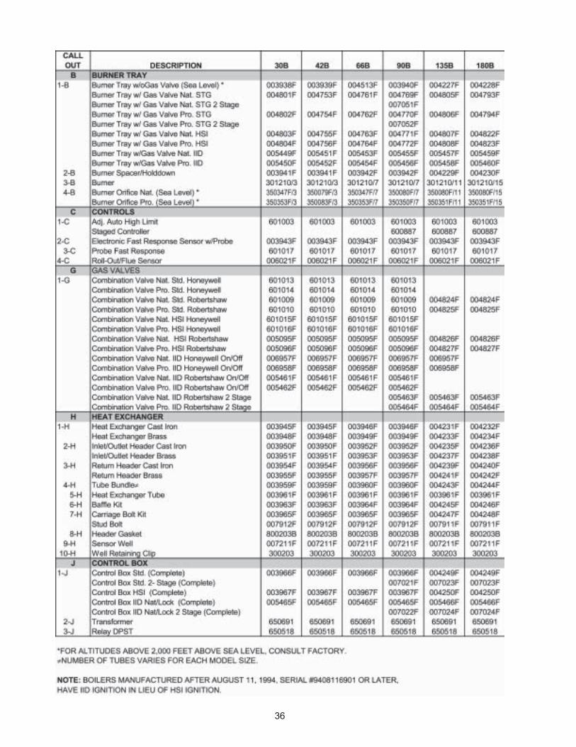
6. REPLACEMENT PARTS LISTNOTE: To supply the correct part it is important that yousupply the model number, serial number and type of gaswhen applicable.
Any part returned for replacement under standardcompany warranties must be properly tagged withRAYPAK return parts tag, completely filled in with theheater serial number, model number etc., and shippedto Raypak freight prepaid.
If determined defective by Raypak and within war-ranty, the part will be returned in kind or equal substitu-tion, freight collect. Credit will not be issued.
RAYPAK, INC.2151 Eastman Avenue
Oxnard, CA 93030
34
9. Fast-Response Temperature Sensor ModuleReplacementa) Shut-off electrical power to the boiler.b) Remove control cover screws and open
control compartment.c) Disconnect wiring to the board.d) Carefully pull out the control board from the
nylon pin supports.e) Reverse above procedure to re-install.
10. Fast-Response Temperature Sensor ProbeReplacementa) Shut-off electrical power to the boiler.b) Shut-off water supply to the boiler and open
drain valve to remove water to the sensorprobe level.
c) Remove control cover screws and opencontrol compartment.
d) Disconnect wire leads from control board.e) Remove upper access panel. f) Remove sensor probe from in/out header.g) Reverse above procedure to re-install.
11. Circulator Replacementa) Shut-off electrical power to the boiler.b) Shut-off water supply and open drain valve
to remove water in the piping at the pumplevel.
CAUTION: To avoid damage to electrical componentskeep water from getting into the control compartmentsand gas valve.
c) Disconnect wiring and conduit connections tothe pump.
d) Disconnect the bypass tube connections tothe inlet flange.
e) Remove the nuts and bolts at the inlet andoutlet flanges. Remove old gaskets.
f) Remove the pump.g) Reverse the above procedure to re-install.
Use new gaskets and make sure they are seated properly when tightening the nutsand bolts.

35
36

37

LIMITED PARTS WARRANTYRESIDENTIAL HEATING BOILERS
MODELS 42 TO 180SCOPE:
Raypak, Inc. (�Raypak�) warrants to the original owner that all parts of this boiler which are actually manufactured by Raypak will be freefrom failure under normal use and service for the specified warranty periods and subject to the conditions set forth in this Warranty. Laborcharges and other costs for parts removal or reinstallation, shipping and transportation are not covered by this Warranty but are theowner�s responsibility.
ANY PART MANUFACTURED BY RAYPAK:One (1) year warranty from date of boiler installation, or eighteen (18) months from date of factory shipment based on Raypak�s records,whichever comes first.SATISFACTORY PROOF OF INSTALLATION DATE, SUCH AS INSTALLER INVOICE, IS REQUIRED. THIS WARRANTY WILL BE VOID IF THEBOILER RATING PLATE IS ALTERED OR REMOVED.
HEAT EXCHNAGER WARRANTY:Second through tenth years from date of installation, Raypak warrants that the copper and cast iron waterway are free from defects inmaterial and workmanship. If any of these parts are found defective Raypak will replace or repair free of charge subject to conditionslisted under �Scope� above.Eleventh through twentieth years from date of installation, Raypak warrants that the copper and cast iron waterways are free fromdefects in material and workmanship. If any of these parts are found defective Raypak will replace the original parts and payment of aproportionate charge equal to 1/120th of the list price of such parts, at the time the warranty claim is made, for each month, or portion thereof, beyond the tenth year.
ADDITIONAL WARRANTY EXCLUSIONS:This warranty does not cover failures or malfunctions resulting from:1. Failure to properly install, operate or maintain the boiler in accordance with our printed instructions provided;2. Abuse, alteration, accident, fire, flood and the like;3. Sediment or lime buildup, freezing, or other conditions causing inadequate water circulation;4. High velocity flow exceeding boiler design rates;5. Failure of connected systems devices, such as pump or controller;6. Use of non-factory authorized accessories or other components in conjunction with the boiler system;7. Failure to eliminate air from, or replenish water in, the connected water system;8. Chemical contamination of combustion air or use of chemical additives to water;9. Boilers installed in buildings other that one- or two-family dwellings.
PARTS REPLACEMENT:Under this Warranty, Raypak will furnish a replacement for any failed part. The failed part must first be returned to Raypak if requested,with transportation charges prepaid, and all applicable warranty conditions satisfied. The replacement part will be warranted for only theunexpired portion of the original warranty. Raypak makes no warranty whatsoever on parts manufactured by others, but Raypak willapply any such warranty as may be provided by the parts manufacturers.
TO MAKE WARRANTY CLAIM:Promptly notify the original installer, supplying the model and serial numbers of the unit, date of installation and description of the problem.The installer must then notify a Raypak distributor for instructions regarding the claim. If neither the installer nor the distributor is available,contact Service Manager, Raypak, Inc., 2151 Eastman Avenue, Oxnard, CA 93030 or call (805) 278-5300. In all cases proper authoriza-tion must first be received from Raypak before replacement of any part.
EXCLUSIVE WARRANTY - LIMITATION OF LIABILITY:This is the only warranty given by Raypak. No one is authorized to make any other warranties on Raypak�s behalf. THIS WARRANTY ISIN LIEU OF ALL OTHER WARRANTIES, EXPRESS OR IMPLIED, INCLUDING BUT NOT LIMITED TO IMPLIED WARRANTIES OF MERCHANTABIL-ITY AND FITNESS FOR A PARTICULAR PURPOSE. RAYPAK�S SOLE LIABILITY AND THE SOLE REMEDY AGAINST RAYPAK WITH RESPECTTO DEFECTIVE PARTS SHALL BE AS PROVIDED IN THIS WARRANTY. IT IS AGREED THAT RAYPAK SHALL HAVE NO LIABILITY, WHETHERUNDER THIS WARRANTY, OR IN CONTRACT, TORT, NEGLIGENCE OR OTHERWISE, FOR ANY SPECIAL, CONSEQUENTIAL, OR INCIDENTAL,DAMAGE, INCLUDING DAMAGE FROM WATER LEAKAGE. Some states do not allow limitations on how long an implied warranty lasts, orfor the exclusion of incidental or consequential damages. So the above limitation or exclusion may not apply to you.This Limited Warranty gives you specific legal rights. You may also have other rights which may vary from state to state. We suggest thatyou complete the information below and retain this certificate in the event warranty service is needed. Reasonable proof of the effectivedate of the warranty (date of installation) must be presented, otherwise, the effective date will be based on the date of manufacture plusthirty (30) days.
_____________________________________________________ ______________________________________________Name of Owner Name of Installer_____________________________________________________ ______________________________________________Address Address_____________________________________________________ ______________________________________________
_____________________________________________________ ______________________________________________Model No. Serial No.
Date of Installation_____________________________________ Date of Initial Operation___________________________
RAYPAK, INC. � 2151 Eastman Avenue � Oxnard, CA 93030 � (805) 278-5300 � Fax (800) 872-9725 � www.raypak.com
P/N: 240419
Catalog No.: 1910.10HEffective: 01-01-04Replaces: 05-15-03

Raypak, Inc., 2151 Eastman Avenue, Oxnard, CA 93030 (805) 278-5300 FAX (800) 872-9725Raypak Canada LTD, 2805 Slough Street, Mississauga, Ontario, Canada L4T 1G2 (905) 677-7999 FAX (905) 677-8036
Litho in U.S.A.
www.raypak.com