Embed Size (px)
Citation preview
.
PSG 1700, Léon-Harmel Québec (Québec)
G1N 4R9
Installation and Operating Instructions for the CADDY ADD-ON wood burning
furnace
READ THE MANUAL THOROUGHLY BEFORE OPERATING THE FURNACE
CONGRATULATIONS!
You have purchased one of the finest wood
add-on furnaces available on the market.
Your furnace will provide years of satisfaction and safe operation.
Please keep this document Certified for Canada and the United States by Omni-Test Laboratories.
45215 Revised : October 21st, 2009
1
TABLE OF CONTENTS INTRODUCTION ......................................................................................................................................... 2
1. CHIMNEY AND DRAFT ........................................................................................................................ 2
2. SAFETY RULES ....................................................................................................................................... 2
GENERAL REQUIREMENTS ................................................................................................................... 2 ODOUR FROM THE PAINT ...................................................................................................................... 3 ASH DISPOSAL ......................................................................................................................................... 3 CREOSOTE BUILD-UP AND REMOVAL ............................................................................................... 3 SMOKE DETECTOR ................................................................................................................................. 4 DOOR GLASS ............................................................................................................................................ 4 GLASS SPECIFICATIONS ........................................................................................................................ 4 ASH DRAWER ........................................................................................................................................... 4 ASH GRATE ............................................................................................................................................... 4
3. APPLIANCE INSTALLATION .............................................................................................................. 5
UNIT LOCATION ...................................................................................................................................... 5 MATCHING THE TRANSFER DUCT BETWEEN THE TWO HEAT GENERATORS .......................... 5 MINIMUM CLEARANCES TO COMBUSTIBLE MATERIALS FOR CADDY ADD-ON ..................... 7 PIPE CONNECTOR AND DAMPER ......................................................................................................... 8 DAMPER .................................................................................................................................................... 9 COMBUSTION AIR ................................................................................................................................... 9 ELECTRICAL CONNECTIONS .............................................................................................................. 10 THERMOSTAT ........................................................................................................................................ 10 FAN CONTROL ....................................................................................................................................... 11
4. OPERATING INSTRUCTIONS ............................................................................................................ 11
LIGHTING ................................................................................................................................................ 12 PREHEATING .......................................................................................................................................... 12 HEATING ................................................................................................................................................. 12 EARLY SIGNS OF OVERFIRED FURNACE ......................................................................................... 13 WOOD AS HEATING FUEL .................................................................................................................... 13 CHIMNEY FIRES ..................................................................................................................................... 14 PROLONGED POWER OUTAGE ........................................................................................................... 14
5. MAINTENANCE .................................................................................................................................... 15
MAINTENANCE OF THE EXCHANGERS ............................................................................................ 15 CHIMNEY MAINTENANCE .................................................................................................................. 16 SMOKE PIPE INSPECTION .................................................................................................................... 16 DOOR GASKET MAINTENANCE ......................................................................................................... 16
6. WIRING DIAGRAM CADDY ADD-ON .............................................................................................. 17
7. TECHNICAL DATA CADDY ADD-ON FURNACE .......................................................................... 18
8. DUCTS AND DAMPERS DIMENSIONS ............................................................................................. 19
9. CADDY ADD-ON BRICKS LAYOUT.................................................................................................. 20
10. APPENDIX 1 ......................................................................................................................................... 21
11. TROUBLESHOOTING ........................................................................................................................ 22
PSG LIMITED LIFETIME WARRANTY ............................................................................................... 23
2
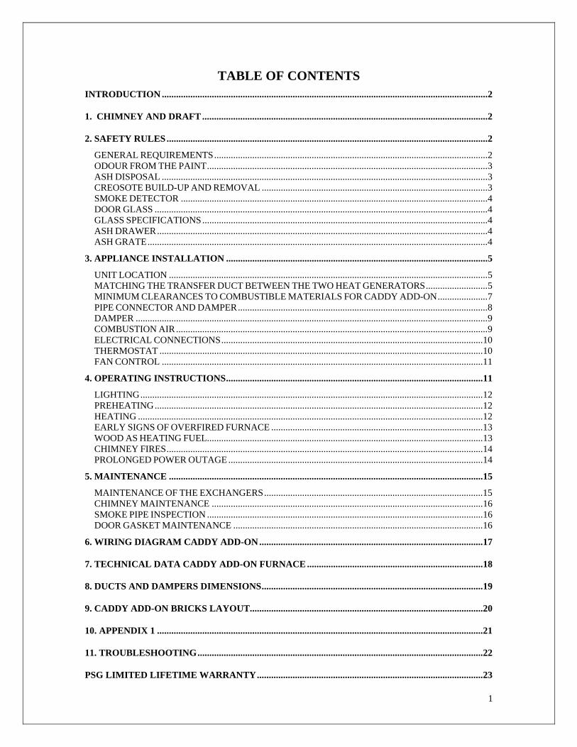
INTRODUCTION Take note that this furnace operates like an EPA wood burning stove. This applies to the firing, the embers and the minimum combustion air which depends on the type and the grade of the combustible. This model line is certified as meeting the emissions limits in 40 C.F.R. part 60, section 60.532 (B) per EPA methods 28 and 5G-3, February 1988. To optimize the efficiency of your furnace, follow the following advices:
Respect the local codes (when in doubt, consult your local dealer).
Make sure your furnace is installed according to the instructions on the certification plate.
All controls adjustments must be performed by a qualified technician. The controls settings and the blower speed must conform to the recommendations of the Warm Air Heating and Air Conditioning National Association and respect the recommended static pressure ranges in the warm air plenum of the furnace (see General Technical data, static pressure).
The wood burning Caddy Add-on furnace is approved for in-line connection to an
existing oil furnace with a firing rate of 0.8 G.P.H. (US) to 1.2 G.P.H. (US) or any gas or electric furnace with comparable heat output.
1. CHIMNEY AND DRAFT
This furnace must be connected to a chimney certified for wood burning heating appliances; a 7” connector and chimney is highly recommended. If draft exceed –0.06 in. W.C a barometric damper should be installed on the smoke pipe. Never install a manual damper.
The barometric damper must be adjusted so that the maximum draft measured at the furnace outlet does not exceed -0.06 in. w.c. Please note that a draft exceeding -0.06 in. w.c. could produce an uncontrollable fire. On the other hand, the minimum draft required is -0.04 in. w.c. in the evacuation pipe on the wood side. 2. SAFETY RULES GENERAL REQUIREMENTS Make sure the chimney outlet and the pipes are clean and in good condition. Do not use chemical products or liquid fuel to light the fire. Do not burn wood coated with paint, glue or chemical products. Do not burn wastes or flammable liquids such as gasoline, naphtha or motor oil. Do not install an automatic feeder on this furnace. Do not store wood in the vicinity of the furnace. Respect the required clearances between
combustible materials and the source of heat.
Average emissions rate: 6.56 g/hr Average heating efficiency: 71.43%

3
WARNING
-THE ASH DRAWER AND EXCHANGERS ACCESS PANEL GET VERY HOT, DO NOT HANDLE WITH BARE HANDS.
ODOUR FROM THE PAINT The furnace will release some smoke and odors when first fired; this is normal and will stop when the paint has finished curing. Burn the unit at high rate with windows opened until the smoke and smell is vented out. ASH DISPOSAL Ashes must be placed in a metal container with a tight fitting lid. The ash container should be stored outdoors, well away from all combustible materials. If the ashes are intended to be buried in soil, wait until all cinders have thoroughly cooled before burying. CREOSOTE BUILD-UP AND REMOVAL When wood is burned slowly, it produces tar and other organic vapors which, when combined with moisture, produce creosote. The creosote vapors condense in a relatively cool chimney and flue. As a result, creosote residues accumulate on the chimney and flue linings. N.B. To minimize the frequency of the chimney cleaning, buy your firewood at least one year before using it. Store in a dry place in order to obtain the minimum moisture rate and optimize the efficiency. Do not store wood or combustible materials within the installation minimum clearances and space required to reload the appliance and remove the ashes. When ignited, creosote produces an extremely hot fire inside the chimney. To avoid this situation, it is important to do the rotation of wood. Inspect the chimney system at regular intervals to determine a cleaning cycle. A weekly cleaning might be required during mild temperature periods but a monthly cleaning should be sufficient during cold periods. If a significant layer of creosote has accumulated, it should be removed immediately to eliminate the risk of a chimney fire. Remember that a small hot fire is preferable to a large smoldering one that can deposit creosote within the system. An emergency plan is necessary in case of a chimney fire. It’s important to clean the exchangers thoroughly at the end of the season to prevent corrosion.
4
SMOKE DETECTOR We highly recommend the use of a smoke detector. It must be installed at least 15 feet (4,57 m) from the appliance in order to prevent a false alarm when refueling the fire. DOOR GLASS To maintain a clean and safe installation, do not build your fire too close to the glass or allow the logs to lean on the glass. Do not operate your furnace at too low a setting. Keep the air inlet opened long enough during the fire start-up to prevent the fire from going out, which would soot up the door glass. An intense fire will help keeping the glass clean. However, in the event that your glass gets too dirty, which should not occur, you will have to clean it using a wet cloth and an oven cleaner. The glass can be cleaned ONLY when the unit has cooled down. Do not use abrasive cleanser. You can find special cleansers for wood stove glasses in any wood stove or hardware store. WARNING: Avoid knocking or scratching the glass which could be damaged. GLASS SPECIFICATIONS The glass is made of Neoceram type of glass, 3/16” – (5 mm) thick. Do not operate your furnace with a broken glass, as this could seriously damage your appliance. You can purchase a replacement glass from your PSG dealer.
ASH DRAWER Your appliance is equipped with an ash drawer to collect ashes produced by the combustion of wood. This drawer must not be left opened during combustion as this will cause over firing and serious damage to the furnace*. The drawer must be cleaned regularly.
ASH GRATE In case of ash grate damage, contact your dealer to get a replacement. The steel cover on the ash grate is meant to optimize the temperature inside the combustion chamber and should only be removed to empty the ashes.
*It is mandatory that the door and the ash drawer be kept closed while the appliance is in use. Maintain all seals in good condition ; in case of deterioration, contact your dealer for replacement.
5
3. APPLIANCE INSTALLATION Before installation, please read the instructions carefully and make sure you understand them:
The furnace must be installed in a state of the art manner. Installation must be made in
accordance with the CSA B.365(Canada) and NFPA 211(USA) standards concerning the normalization of solid fuel units. For installation in United Sates, also refer to NFPA 90B(USA) « Warm Heating and Air Conditioning Systems ». If modifications have to be made to the existing furnace, these have to be conform with the CSA B.139 (Canada) and NFPA 31 (USA) regulation for oil furnaces.
Inspect the furnace to make sure that nothing has been damaged in the shipping. Pull
out the wiring kit and the instructions manual from the firebox of the furnace and the cleaning tools from the heat exchangers. UNIT LOCATION The furnace must be installed where outside air supply will be sufficient for proper combustion. In airtight houses, it might be necessary to install an outside air inlet (see details in: «3- INSTALLATION» COMBUSTION AIR). The furnace must be positioned so that the connector is as short as possible. Minimize the use of 90o elbows.
The owner must ensure a proper installation to allow a safe operation of the appliance.
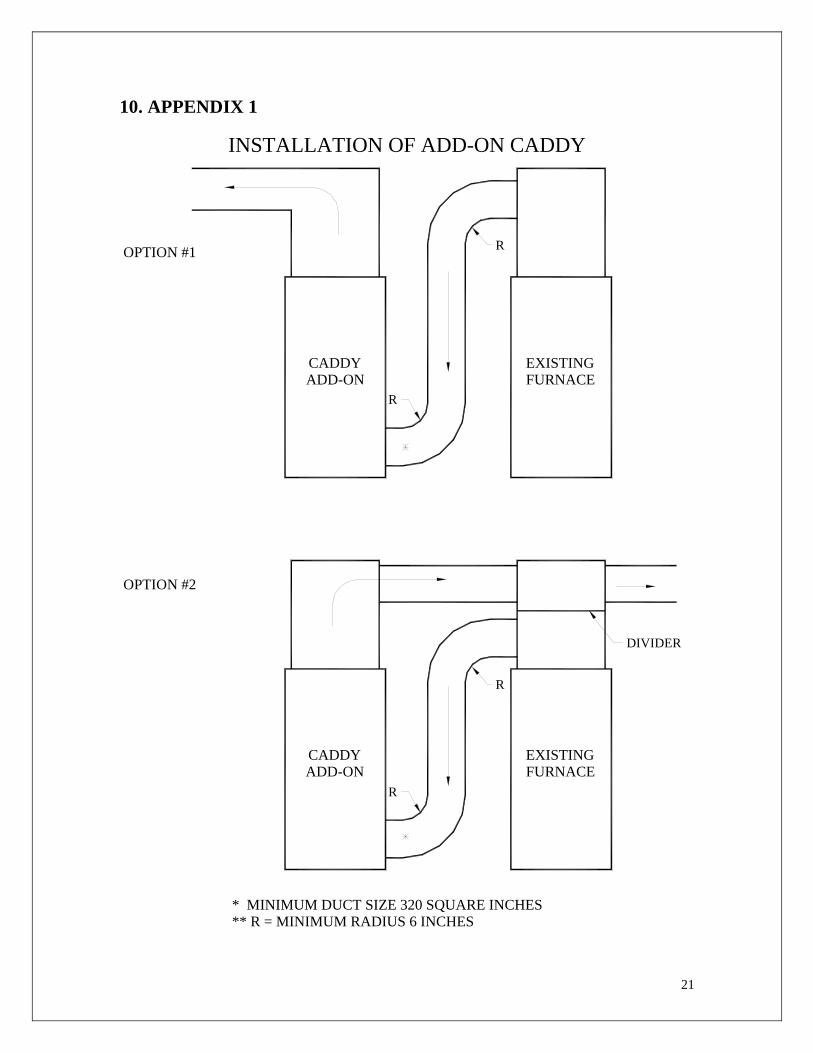
MATCHING THE TRANSFER DUCT BETWEEN THE TWO HEAT GENERATORS
Install the plenum and heating ducts in line as in option 1 of appendix 1. In series
connection should be considered only if in line connection is not feasible. If the ducts are installed in series (appendix 1, option 2) and the oil furnace’s fan limit
control is mounted on the plenum, the divider in the plenum must be installed at least 5” (127 mm) above the fan limit control casing. This divider must be air tight.
Do not install connecting ducts in a way that would allow inversion of the air flow. Do not use elbows with a radius less than 6 inches (153 mm). The transfer duct between the existing furnace and the add-on must be at least 320
square inches(0.2m2) and deviations radius must be at least 6”(153mm). (see the drawing on the following page)
Do not remove any safety device from the existing furnace.
6
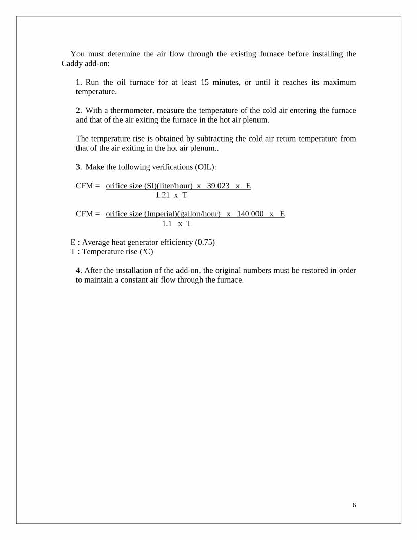
You must determine the air flow through the existing furnace before installing the Caddy add-on:
1. Run the oil furnace for at least 15 minutes, or until it reaches its maximum temperature. 2. With a thermometer, measure the temperature of the cold air entering the furnace and that of the air exiting the furnace in the hot air plenum. The temperature rise is obtained by subtracting the cold air return temperature from that of the air exiting in the hot air plenum.. 3. Make the following verifications (OIL): CFM = orifice size (SI)(liter/hour) x 39 023 x E 1.21 x T CFM = orifice size (Imperial)(gallon/hour) x 140 000 x E
1.1 x T E : Average heat generator efficiency (0.75) T : Temperature rise (ºC)
4. After the installation of the add-on, the original numbers must be restored in order to maintain a constant air flow through the furnace.
7
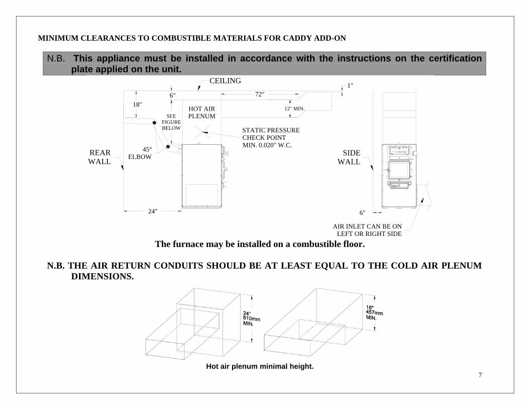
MINIMUM CLEARANCES TO COMBUSTIBLE MATERIALS FOR CADDY ADD-ON
N.B. This appliance must be installed in accordance with the instructions on the certification plate applied on the unit.
SEEFIGUREBELOW STATIC PRESSURE
CHECK POINTMIN. 0.020" W.C.
24"
REARWALL
45° ELBOW
AIR INLET CAN BE ON LEFT OR RIGHT SIDE
6"
SIDEWALL
18"
CEILING
HOT AIRPLENUM
6" 72"1"
12" MIN.
The furnace may be installed on a combustible floor.
N.B. THE AIR RETURN CONDUITS SHOULD BE AT LEAST EQUAL TO THE COLD AIR PLENUM
DIMENSIONS.
Hot air plenum minimal height.
8
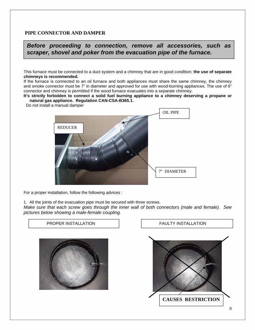
PIPE CONNECTOR AND DAMPER
This furnace must be connected to a duct system and a chimney that are in good condition; the use of separate chimneys is recommended. If the furnace is connected to an oil furnace and both appliances must share the same chimney, the chimney and smoke connector must be 7” in diameter and approved for use with wood-burning appliances. The use of 6” connector and chimney is permitted if the wood furnace evacuates into a separate chimney. It’s strictly forbidden to connect a solid fuel burning appliance to a chimney deserving a propane or
natural gas appliance. Regulation CAN-CSA-B365.1. Do not install a manual damper For a proper installation, follow the following advices : 1. All the joints of the evacuation pipe must be secured with three screws. Make sure that each screw goes through the inner wall of both connectors (male and female). See pictures below showing a male-female coupling.
Before proceeding to connection, remove all accessories, such as scraper, shovel and poker from the evacuation pipe of the furnace.
PROPER INSTALLATION FAULTY INSTALLATION
7" DIAMETER
CAUSES RESTRICTION
REDUCER
OIL PIPE

9
2. A minimum upward slope of 1/4 inch per horizontal foot must be respected.
DAMPER
The barometric damper must be adjusted so that the maximum draft measured at the furnace outlet is limited to -0.06 in. w.c.. However, the minimum draft to be respected at all times is -0.04 in. w.c. on the solid fuel side. WARNING: DRAFT HIGHER THAN -0.06” W.C. MAY CAUSE AN UNCONTROLLABLE
FIRE.
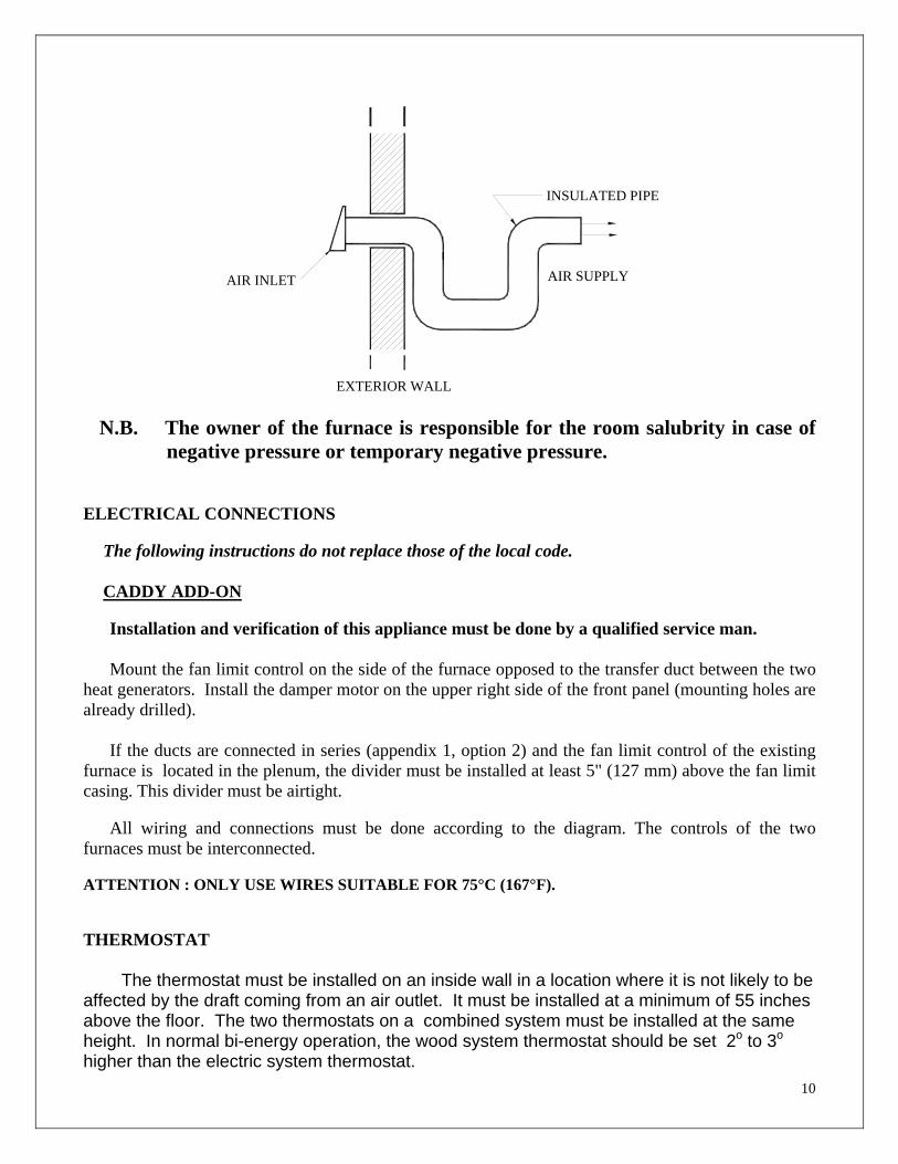
COMBUSTION AIR When the furnace and the chimney are completely cold, it might be necessary to provide fresh air by opening a door or a window for a few minutes while lighting. Take note that a house constructed or renovated in order to be airtight is liable to lack fresh air which is necessary for a proper combustion and operation of heating appliances. When starting up the fire, do not operate appliances which evacuate air outside the house such as:
- Range hood - Air exchanger
- Cloths dryer
- Bathroom fan
- Ventilated central vacuum system
NOTE:
It is recommended to install an outside air inlet of minimum 4” in diameter in or near the room where the heating appliance is installed (see drawing on the next page). When doing so, it is preferable to choose a wall which is not exposed to dominant winds, depending on the conditions surrounding your house.
10
AIR SUPPLY
INSULATED PIPE
EXTERIOR WALL
AIR INLET
N.B. The owner of the furnace is responsible for the room salubrity in case of negative pressure or temporary negative pressure.
ELECTRICAL CONNECTIONS
The following instructions do not replace those of the local code. CADDY ADD-ON Installation and verification of this appliance must be done by a qualified service man. Mount the fan limit control on the side of the furnace opposed to the transfer duct between the two
heat generators. Install the damper motor on the upper right side of the front panel (mounting holes are already drilled).
If the ducts are connected in series (appendix 1, option 2) and the fan limit control of the existing
furnace is located in the plenum, the divider must be installed at least 5" (127 mm) above the fan limit casing. This divider must be airtight.
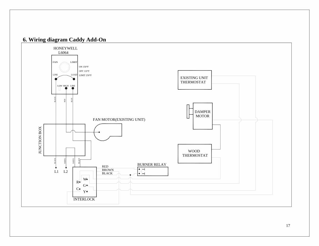
All wiring and connections must be done according to the diagram. The controls of the two furnaces must be interconnected. ATTENTION : ONLY USE WIRES SUITABLE FOR 75°C (167°F). THERMOSTAT The thermostat must be installed on an inside wall in a location where it is not likely to be affected by the draft coming from an air outlet. It must be installed at a minimum of 55 inches above the floor. The two thermostats on a combined system must be installed at the same height. In normal bi-energy operation, the wood system thermostat should be set 2o to 3o higher than the electric system thermostat.
11
FAN CONTROL The fan control settings vary depending on the type of installation. The “fan off” setting is preset at 110o F at the factory. This setting should provide a proper operation in most installations. The “fan on” setting is factory set at 150o F. It is preferable for a prolonged operation of the blower that the “fan off” setting be low enough. But a “fan off” setting too low will cause undesirable cold air circulation. To modify the setting, turn the indicator at the desired position on the temperature scale of the fan limit control. The adjustment of all controls must be performed by a qualified technician. The controls and the blower speed settings must conform to the recommendations of the “Warm Air Heating and Air Conditioning National Association”.
The switch located below the fan limit control operates the low speed either at the “on” position or the “off” position. For a better efficiency we recommend to leave the high speed on automatic for heating and to use the low speed for continuous air circulation.
It is possible that the blower and motor pulleys have to be replaced in order to obtain the desired air flow through the system. (The use of a more powerful motor is permitted on the belt driven blowers). Direct drive motors may not be replaced but they may be upgraded by replacing the capacitor.
WARNING : the blower of the existing furnace may not be changed. 4. OPERATING INSTRUCTIONS Start the existing heat generator periodically to make sure it is in good working condition. On the wood furnaces, the thermostat controls the air inlet damper. When the thermostat calls for heat, the damper opens and the combustion is stirred up. When the furnace gets hot enough, the fan limit control activates the blower motor at the speed selected for wood heating. The chain that links the air inlet latch to the damper motor must have a 1/8 inch play. When there is no call for heat, the air inlet latch must be completely closed and the chain must be hooked up to the damper motor at the “8 o’clock” position. *
*(With all reserve for the minimum air intake to be increased depending on the type and quality of the combustible).
12
LIGHTING NEVER USE CHEMICALS OR FLAMMABLE LIQUIDS TO LIGHT THE FURNACE 1. Open the door Note: If there already is a good ember bed in the furnace, go to step b) Pre-heating. 2. Remove the steel plate on the ash grate and empty the ashes in the ash drawer. 3. Put the steel plate back in place, making sure it is properly seated. The steel plate on the
ash grate is intended to optimize the heat retention into the combustion chamber. 4. Place one or two pieces of dry kindlings at the front of the furnace. 5. Place newspaper strips on top of the kindlings. 6. Cover the newspaper with small pieces of dry wood. 7. Add newspaper strips, then light the fire as low as possible and leave the door 1/2" (13
mm) opened. If lighting fails, you might experience a smoke back draft through the air inlets.
PREHEATING 1. Once the kindling is well ignited or the coals revived, put 2 or 3 fire logs in such a way that
the flames can interlace between the logs and close the door. It is important to respect these loading sequences in order for the wood to burn from the front of the furnace towards the back in a cigar like manner..
2. Wait 15 to 20 minutes then proceed with loading the furnace. HEATING 1. When reloading the furnace, first spread the embers at the center of the combustion
chamber before adding new logs. 2. Do not overload. Air must circulate freely in the upper part of the combustion chamber in
order to obtain an efficient operation of the appliance. Note that a small hot fire will produce much less creosote than a large smouldering one.
IMPORTANT: DURING THE HEATING PROCESS, REMOVE THE ASHES AND WOOD THAT COULD OBSTRUCT THE 1/4" (6.4 mm) HOLE LOCATED BELOW THE DOOR INSIDE THE FURNACE.
13
PROCEDURE TO OPEN THE LOADING DOOR
TO MINIMIZE THE RISK OF SMOKE SPILLAGE, OPEN THE DOOR 1” AND WAIT ABOUT 10 SECONDS BEFORE OPENING COMPLETELY. THE PURPOSE IS TO STABILIZE THE PRESSURE INSIDE THE FURNACE.
EARLY SIGNS OF OVERFIRED FURNACE 1. Roaring fire. 2. Chimney connector is glowing red. 3- Extreme heat coming from the furnace. If this occurs, DO NOT OPEN THE DOOR, shut-off the air inlet completely, and wait until the glow has completely subsided.
ALWAYS KEEP THE DOOR AND THE ASH DRAWER CLOSED (except for lighting and maintenance).
WOOD AS HEATING FUEL
DO NOT USE CHEMICALS OR FLAMABLE LIQUIDS TO LIGHT THE FIREPAS
DO NOT BURN TRASH, GASOLINE, NAPHTA, MOTOR OIL OR OTHER SUCH MATERIALS.
We recommend that you burn seasoned hard wood only.
There are two important factors to be considered when choosing a type of wood: the moisture content and the wood density. Hardwood, such as maple, oak or beech will provide better results because of the high density and minimal tar produced during combustion. It is highly recommended to use wood that has been dried at least six months. Do not use coal as heating fuel in this appliance.
Whenever a high rate of smoke is noticed in the room, you must: 1. Open doors and windows. 2. Make sure the furnace door is closed as well as the damper (if necessary, lower the
thermostat starting point or undo the chain of the damper and close the barometric control manually).
3. When the furnace has cooled down, inspect the chimney to detect obstructions and consult
a specialist to determine the cause.
14
CARBON MONOXYDE IS A LETHAL GAS (ODOURLESS AND COLOURLESS), WHICH YOU MUST BEWARE OF. CHIMNEY FIRES This might occur when the fire gets extremely hot and may be triggered by the burning of cardboard, branches or small pieces of wood when the flame ignites the creosote residues accumulated in the evacuation system. The usual signs of chimney fire are: 1. Rumbling 2. The flue gets extremely hot 3. Flames or sparks are coming out of the chimney In case of a chimney fire, call your local fire department immediately and sprinkle the
roof around the chimney with water. Make sure that the furnace door is closed as well as the damper (if necessary, lower the thermostat setting or release the chain of the damper and CLOSE the barometric damper manually). If the fire gets uncontrollable due to an improper use or because the draft is too strong, follow the same procedure as in a chimney fire except that you will have to OPEN the barometric damper manually. LOCAL FIRE DEPARTMENT. Phone number: ___________________________________ PROLONGED POWER OUTAGE
In case of prolonged power outage (more than 10 minutes), in order to diminish the risk of overheating, it is recommended to :
- Make sure that the furnace’s damper is closed. - Open the filter compartment of the existing furnace in order to facilitate the circulation
of air, through natural gravity, around the wood add-on combustion chamber.
15
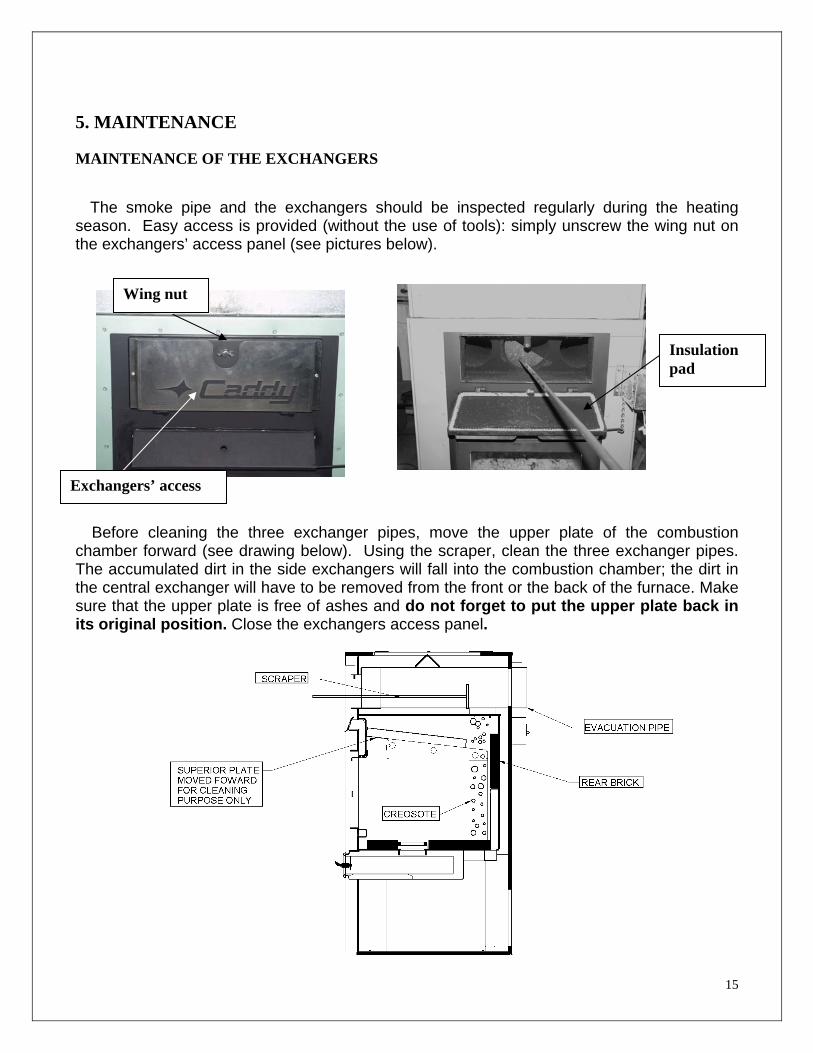
5. MAINTENANCE MAINTENANCE OF THE EXCHANGERS The smoke pipe and the exchangers should be inspected regularly during the heating season. Easy access is provided (without the use of tools): simply unscrew the wing nut on the exchangers’ access panel (see pictures below).
Before cleaning the three exchanger pipes, move the upper plate of the combustion chamber forward (see drawing below). Using the scraper, clean the three exchanger pipes. The accumulated dirt in the side exchangers will fall into the combustion chamber; the dirt in the central exchanger will have to be removed from the front or the back of the furnace. Make sure that the upper plate is free of ashes and do not forget to put the upper plate back in its original position. Close the exchangers access panel.
Wing nut
Exchangers’ access
Insulation pad
16
CHIMNEY MAINTENANCE One of the most efficient methods to sweep the chimney is using a hard brush. Brush downwards so soot and creosote residues will come off the inner surface and fall at the bottom of the chimney where they may be easily removed. The chimney must be checked regularly and if creosote has accumulated, it must be removed to prevent chimney fires. Cleaning on a monthly basis should be sufficient during the coldest months. SMOKE PIPE INSPECTION
- The smoke pipe should be inspected regularly during the heating season. - If possible, the smoke pipe should be dismantled and cleaned.
- The smoke pipe should be inspected to detect any defect.
- If no defect is noticed, put the flue back in place; otherwise, it must be replaced.
- Use only wood as a combustible.
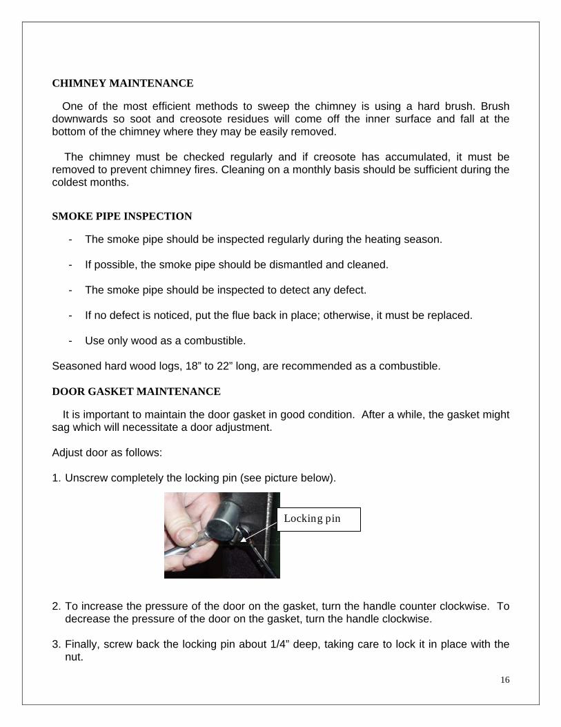
Seasoned hard wood logs, 18” to 22” long, are recommended as a combustible. DOOR GASKET MAINTENANCE It is important to maintain the door gasket in good condition. After a while, the gasket might sag which will necessitate a door adjustment. Adjust door as follows: 1. Unscrew completely the locking pin (see picture below).
2. To increase the pressure of the door on the gasket, turn the handle counter clockwise. To
decrease the pressure of the door on the gasket, turn the handle clockwise.
3. Finally, screw back the locking pin about 1/4” deep, taking care to lock it in place with the nut.
Locking pin
17
6. Wiring diagram Caddy Add-On
BURNER RELAY
L1
JUN
CTI
ON
BO
X
BLA
CK
CY
INTERLOCK
BROWNBLACK
FAN MOTOR(EXISTING UNIT)
W
G
L2
R
WH
ITE
WH
ITE
BLA
CK
RED TT
HONEYWELL L6064
LOW
BLA
CK
LINE
FAN
LIMIT 250°F
OFF 110°FB
LUE
RED
LINE
LOAD
HIGH
ON 150°F
LIMIT
WOOD THERMOSTAT
DAMPER MOTOR
EXISTING UNIT THERMOSTAT

18
7. TECHNICAL DATA CADDY ADD-ON FURNACE
CADDY ADD-ON A 29 1/2"(750mm) B 25 1/2"(648mm) C 47 1/4"(1200mm) D 28 1/2"(724mm) E 24 1/2"(622mm) F 44"(1118mm) G 22 1/8”(562mm) H 14 3/8”(365mm)
FLUE 6"(152mm)
WEIGHT 445Lb (202kg)
TECHNICAL DATA
MODELE TEMP. BTU/HR STATIC PRESSURE
VARIABLE (BOIS) MIN. MAX. °C(°F)
CADDY ADD-ON 26 (78) 140 000 0,2 0,6
H20
19
8. DUCTS AND DAMPERS DIMENSIONS SIMPLIFIED METHOD
DISTRIBUTION SYSTEM
Ducts size (heat)
4 inch outlet reduce by 1”
5 inch outlet reduce by 2” Always by 8” thick
6 inch outlet reduce by 3”
N.B.: The main duct must be reduced every 2 outlets.
Ducts specifications (heat) Dimensions Length Elbow Average equivalence
4” 10’ 1 x 90o Max 4,000 Btu
5” 10’ 1 x 90o Max 6,000 Btu
6” 10’ 1 x 90o Max 7,000 Btu
DAMPER
For a 4” warm air outlet: 2” x 10” damper
For a 5” warm air outlet: 2” x 12” damper or 4” x 10”
For a 6” warm air outlet: 2” x 14” damper or 4” x 12”
WARM AIR SYSTEM INSTALLATION
HOUSE DIMENSIONS Example: 28 x 40 bungalow: 1,120 sq. ft. 28 x 40 x 8: 8,960 cu. ft. x 1.8 Ch. air/hr: 16,128 Btu Exposed walls: 40 + 40 + 28 + 28: 136 x 8: 1,088 cu. ft. x 22: 23,936 Btu Number of windows: 12 of 3 x 4: 144 x 60: 8,640 Btu Number of doors: 2 x 3 x 7: 42 x 100: 4,200 Btu
52,904 Btu Non-insulated basement: 25% Insulated basement: 15% 7,906 Btu
or 54 Btu per sq. ft. 60,840 Btu
FOR ELECTRIC ELEMENTS 80%: 48,672 Btu or 14,28 kW
TO BE ADDED: House 1 1/2 floor = 25% House 2 floors = 40% BEDROOM (for example: 12 x 12)
12 x 12 x 8: 1,152 cu. ft. x 1.8 Ch. air/hr: 2,074 Btu
Exposed walls: 12 + 12 x 8: 192 x 22: 4,224 Btu
Windows: 3 x 4 x 60 720 Btu
7,018 Btu

20
9. CADDY ADD-ON BRICKS LAYOUT
WARNING: INSTALL THE CERAMIC BLANKET PANEL BEFORE
PUTTING BRICKS UP IN THE COMBUSTION CHAMBER
412"
34"5
8"
412"6
4"
9"158"
3 516"
4
412"
9"
312"
1"8
114"
9"
7
1
2
3
3
3
3
3
3
3
3
4
45
55
5
55
5
5
5
5
5
5
5
5
5
55
5
5
5
5
66
7
8
8
8
8
BRICK 4.5X9 SPECIALBRICK 1.25 X 9½ BRICK 4.5X9 SPECIALBRICK 4.5 X 9 BRICK 4X9 SPECIALBRICK 4 X 9 BRICK 4 X 8ASHGRATE 1
81
21
12
4
2
1
32
5
76
8
4
DESCRIPTIONItem QTY
21
10. APPENDIX 1
INSTALLATION OF ADD-ON CADDY
CADDYADD-ON
EXISTING FURNACE
* MINIMUM DUCT SIZE 320 SQUARE INCHES** R = MINIMUM RADIUS 6 INCHES
R
R
OPTION #2
DIVIDER
EXISTING FURNACE
CADDYADD-ON
R
OPTION #1 R
22
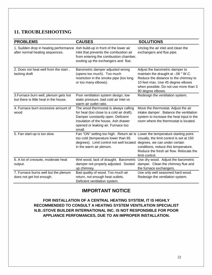
11. TROUBLESHOOTING
PROBLEMS CAUSES SOLUTIONS1. Sudden drop in heating performance after normal heating sequences.
Ash build-up in front of the lower air inlet that prevents the combustion air from entering the combustion chamber, sooting up the exchangers and flue.
Unclog the air inlet and clean the exchangers and flue pipe.
2. Does not heat well from the start , lacking draft
Barometric damper adjusted wrong (opens too much). Too much restriction in the smoke pipe (too long or too many elbows).
Adjust the barometric damper to maintain the draught at -.06 " W.C. Reduce the distance to the chimney to 10 feet max. Use 45 degree elbows when possible. Do not use more than 3 90 degree elbows.
3.Furnace burn well, plenum gets hot but there is little heat in the house.
Poor ventilation system design, low static pressure, bad cold air inlet vs warm air outlet ratio.
Redesign the ventilation system.
4. Furnace burn excessive amount of wood
The wood thermostat is always calling for heat (too close to a cold air draft). Damper constantly open. Deficient insulation of the house. Ash drawer opened or leaking air. Furnace too small.
Move the thermostat. Adjust the air intake damper . Balance the ventilation system to increase the heat input in the room where the thermostat is located.
5. Fan start-up is too slow. Fan “ON” setting too high. Return air is too cold (temperature lower than 65 degrees). Limit control not well located in the warm air plenum.
Lower the temperature starting point. Usually, the limit control is set at 150 degrees, we can under certain conditions, reduce this temperature. Reduce the fresh air flow. Relocate the limit control.
6. A lot of creosote, moderate heat output.
Wet wood, lack of draught. Barometric damper not properly adjusted. Sooted up chimney.
Use dry wood. Adjust the barometric damper. Clean the chimney flue and the furnace exchangers.
7. Furnace burns well but the plenum does not get hot enough.
Bad quality of wood. Too much air return, not enough heat outlets. Deficient ventilation system.
Use only well seasoned hard wood. Redesign the ventilation system.
IMPORTANT NOTICE
FOR INSTALLATION OF A CENTRAL HEATING SYSTEM, IT IS HIGHLYRECOMMENDED TO CONSULT A HEATING SYSTEM VENTILATION SPECIALISTN.B.:STOVE BUILDER INTERNATIONAL INC. IS NOT RESPONSIBLE FOR POOR
APPLIANCE PERFOMANCES, DUE TO AN IMPROPER INSTALLATION.
23
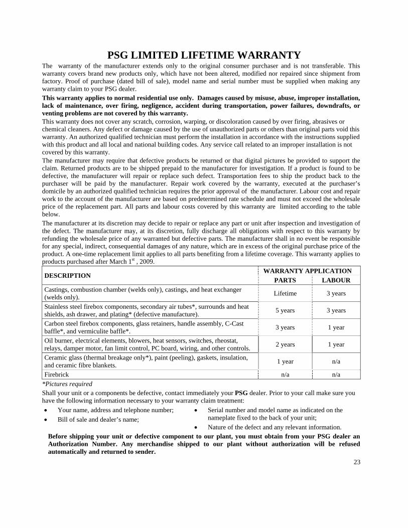
PSG LIMITED LIFETIME WARRANTY The warranty of the manufacturer extends only to the original consumer purchaser and is not transferable. This warranty covers brand new products only, which have not been altered, modified nor repaired since shipment from factory. Proof of purchase (dated bill of sale), model name and serial number must be supplied when making any warranty claim to your PSG dealer. This warranty applies to normal residential use only. Damages caused by misuse, abuse, improper installation, lack of maintenance, over firing, negligence, accident during transportation, power failures, downdrafts, or venting problems are not covered by this warranty. This warranty does not cover any scratch, corrosion, warping, or discoloration caused by over firing, abrasives or chemical cleaners. Any defect or damage caused by the use of unauthorized parts or others than original parts void this warranty. An authorized qualified technician must perform the installation in accordance with the instructions supplied with this product and all local and national building codes. Any service call related to an improper installation is not covered by this warranty. The manufacturer may require that defective products be returned or that digital pictures be provided to support the claim. Returned products are to be shipped prepaid to the manufacturer for investigation. If a product is found to be defective, the manufacturer will repair or replace such defect. Transportation fees to ship the product back to the purchaser will be paid by the manufacturer. Repair work covered by the warranty, executed at the purchaser’s domicile by an authorized qualified technician requires the prior approval of the manufacturer. Labour cost and repair work to the account of the manufacturer are based on predetermined rate schedule and must not exceed the wholesale price of the replacement part. All parts and labour costs covered by this warranty are limited according to the table below. The manufacturer at its discretion may decide to repair or replace any part or unit after inspection and investigation of the defect. The manufacturer may, at its discretion, fully discharge all obligations with respect to this warranty by refunding the wholesale price of any warranted but defective parts. The manufacturer shall in no event be responsible for any special, indirect, consequential damages of any nature, which are in excess of the original purchase price of the product. A one-time replacement limit applies to all parts benefiting from a lifetime coverage. This warranty applies to products purchased after March 1st , 2009.
DESCRIPTION WARRANTY APPLICATION
PARTS LABOUR Castings, combustion chamber (welds only), castings, and heat exchanger (welds only). Lifetime 3 years
Stainless steel firebox components, secondary air tubes*, surrounds and heat shields, ash drawer, and plating* (defective manufacture). 5 years 3 years
Carbon steel firebox components, glass retainers, handle assembly, C-Cast baffle*, and vermiculite baffle*. 3 years 1 year
Oil burner, electrical elements, blowers, heat sensors, switches, rheostat, relays, damper motor, fan limit control, PC board, wiring, and other controls. 2 years 1 year
Ceramic glass (thermal breakage only*), paint (peeling), gaskets, insulation, and ceramic fibre blankets. 1 year n/a
Firebrick n/a n/a *Pictures required Shall your unit or a components be defective, contact immediately your PSG dealer. Prior to your call make sure you have the following information necessary to your warranty claim treatment: • Your name, address and telephone number; • Bill of sale and dealer’s name;
• Serial number and model name as indicated on the nameplate fixed to the back of your unit;
• Nature of the defect and any relevant information. Before shipping your unit or defective component to our plant, you must obtain from your PSG dealer an Authorization Number. Any merchandise shipped to our plant without authorization will be refused automatically and returned to sender.