Embed Size (px)
Citation preview
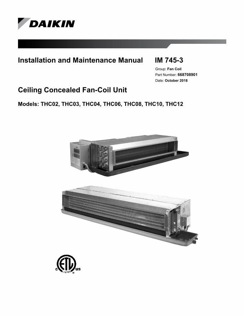
Installation and Maintenance Manual IM 745-3Group: Fan CoilPart Number: 668708901Date: October 2018
Ceiling Concealed Fan-Coil Unit
Models: THC02, THC03, THC04, THC06, THC08, THC10, THC12
IM 745-3 2 www.DaikinApplied.com
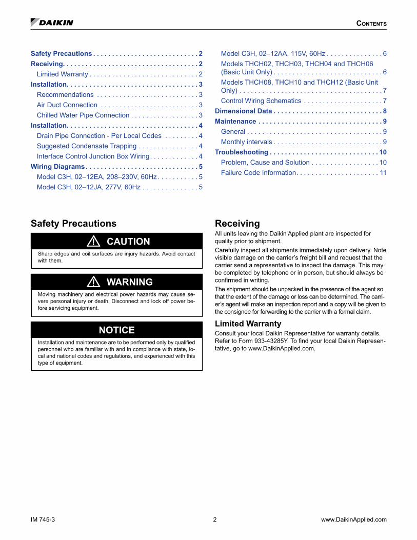
Safety Precautions
NOTICEInstallation and maintenance are to be performed only by qualified personnel who are familiar with and in compliance with state, lo-cal and national codes and regulations, and experienced with this type of equipment.
WARNINGMoving machinery and electrical power hazards may cause se-vere personal injury or death. Disconnect and lock off power be-fore servicing equipment.
CAUTIONSharp edges and coil surfaces are injury hazards. Avoid contact with them.
ReceivingAll units leaving the Daikin Applied plant are inspected for quality prior to shipment. Carefully inspect all shipments immediately upon delivery. Note visible damage on the carrier’s freight bill and request that the carrier send a representative to inspect the damage. This may be completed by telephone or in person, but should always be confirmed in writing.The shipment should be unpacked in the presence of the agent so that the extent of the damage or loss can be determined. The carri-er’s agent will make an inspection report and a copy will be given to the consignee for forwarding to the carrier with a formal claim.
Limited WarrantyConsult your local Daikin Representative for warranty details. Refer to Form 933-43285Y. To find your local Daikin Represen-tative, go to www.DaikinApplied.com.
Contents
Safety Precautions . . . . . . . . . . . . . . . . . . . . . . . . . . . . 2Receiving . . . . . . . . . . . . . . . . . . . . . . . . . . . . . . . . . . . . 2
Limited Warranty . . . . . . . . . . . . . . . . . . . . . . . . . . . . . 2Installation . . . . . . . . . . . . . . . . . . . . . . . . . . . . . . . . . . . 3
Recommendations . . . . . . . . . . . . . . . . . . . . . . . . . . . 3Air Duct Connection . . . . . . . . . . . . . . . . . . . . . . . . . . 3Chilled Water Pipe Connection . . . . . . . . . . . . . . . . . . 3
Installation . . . . . . . . . . . . . . . . . . . . . . . . . . . . . . . . . . . 4Drain Pipe Connection - Per Local Codes . . . . . . . . . 4Suggested Condensate Trapping . . . . . . . . . . . . . . . . 4Interface Control Junction Box Wiring. . . . . . . . . . . . . 4
Wiring Diagrams . . . . . . . . . . . . . . . . . . . . . . . . . . . . . . 5Model C3H, 02–12EA, 208–230V, 60Hz . . . . . . . . . . . 5Model C3H, 02–12JA, 277V, 60Hz . . . . . . . . . . . . . . . 5
Model C3H, 02–12AA, 115V, 60Hz . . . . . . . . . . . . . . . 6Models THCH02, THCH03, THCH04 and THCH06 (Basic Unit Only) . . . . . . . . . . . . . . . . . . . . . . . . . . . . . 6Models THCH08, THCH10 and THCH12 (Basic Unit Only) . . . . . . . . . . . . . . . . . . . . . . . . . . . . . . . . . . . . . . 7Control Wiring Schematics . . . . . . . . . . . . . . . . . . . . . 7
Dimensional Data . . . . . . . . . . . . . . . . . . . . . . . . . . . . . 8Maintenance . . . . . . . . . . . . . . . . . . . . . . . . . . . . . . . . . 9
General . . . . . . . . . . . . . . . . . . . . . . . . . . . . . . . . . . . . 9Monthly intervals . . . . . . . . . . . . . . . . . . . . . . . . . . . . . 9
Troubleshooting . . . . . . . . . . . . . . . . . . . . . . . . . . . . . 10Problem, Cause and Solution . . . . . . . . . . . . . . . . . . 10Failure Code Information. . . . . . . . . . . . . . . . . . . . . . 11
www.DaikinApplied.com 3 IM 745-3
InstallatIon
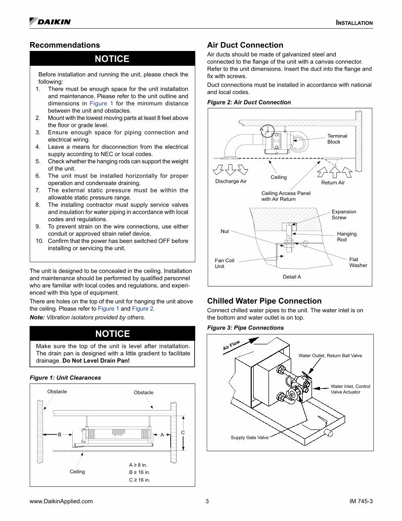
Recommendations
NOTICEBefore installation and running the unit, please check the following:
1. There must be enough space for the unit installation and maintenance. Please refer to the unit outline and dimensions in Figure 1 for the minimum distance between the unit and obstacles.
2. Mount with the lowest moving parts at least 8 feet above the floor or grade level.
3. Ensure enough space for piping connection and electrical wiring.
4. Leave a means for disconnection from the electrical supply according to NEC or local codes.
5. Check whether the hanging rods can support the weight of the unit.
6. The unit must be installed horizontally for proper operation and condensate draining.
7. The external static pressure must be within the allowable static pressure range.
8. The installing contractor must supply service valves and insulation for water piping in accordance with local codes and regulations.
9. To prevent strain on the wire connections, use either conduit or approved strain relief device.
10. Confirm that the power has been switched OFF before installing or servicing the unit.
The unit is designed to be concealed in the ceiling. Installation and maintenance should be performed by qualified personnel who are familiar with local codes and regulations, and experi-enced with this type of equipment.There are holes on the top of the unit for hanging the unit above the ceiling. Please refer to Figure 1 and Figure 2.Note: Vibration isolators provided by others.
NOTICEMake sure the top of the unit is level after installation. The drain pan is designed with a little gradient to facilitate drainage. Do Not Level Drain Pan!
Figure 1: Unit Clearances
Obstacle
Ceiling
B A C
A ≥ 8 in.B ≥ 16 in.C ≥ 16 in.
Obstacle
Air Duct ConnectionAir ducts should be made of galvanized steel and connected to the flange of the unit with a canvas connector. Refer to the unit dimensions. Insert the duct into the flange and fix with screws. Duct connections must be installed in accordance with national and local codes.
Figure 2: Air Duct Connection
Discharge Air Return AirCeiling
Ceiling Access Panelwith Air Return
TerminalBlock
A
Fan Coil Unit
FlatWasher
HangingRod
Expansion Screw
Nut
Detail A
Chilled Water Pipe ConnectionConnect chilled water pipes to the unit. The water inlet is on the bottom and water outlet is on top.
Figure 3: Pipe Connections
Water Inlet, Control Valve Actuator
Water Outlet, Return Ball ValveAir Flow
Supply Gate Valve
IM 745-3 4 www.DaikinApplied.com
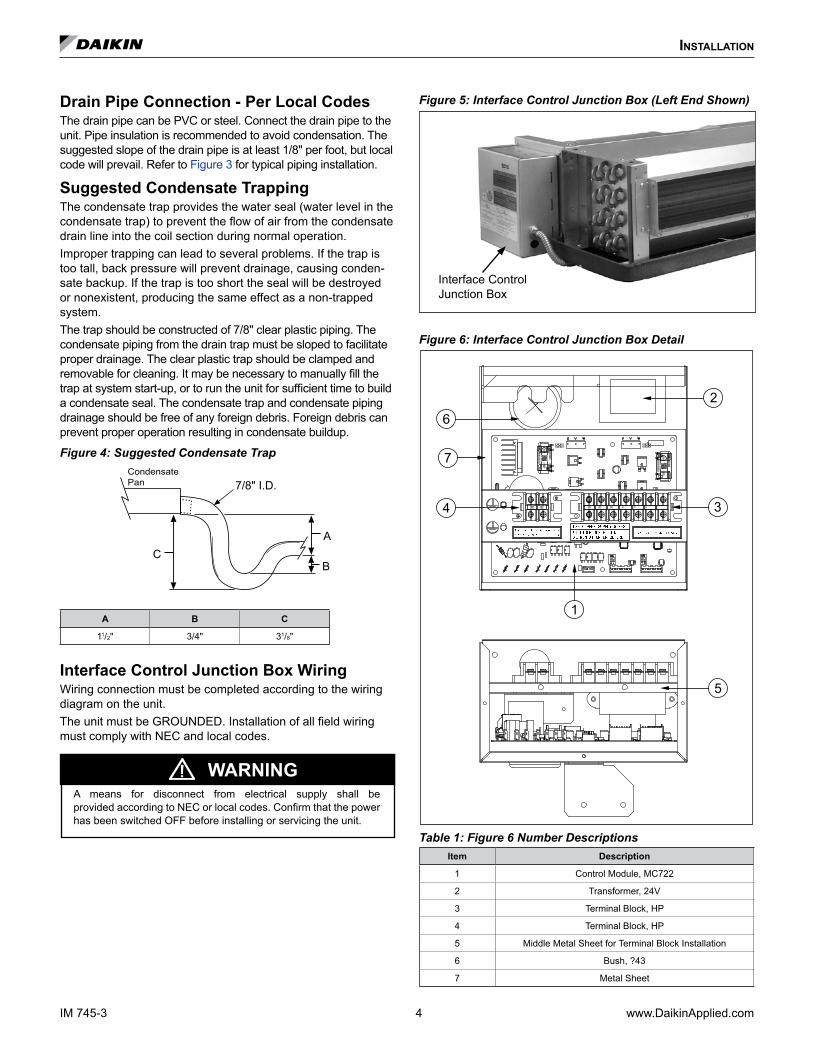
Drain Pipe Connection - Per Local CodesThe drain pipe can be PVC or steel. Connect the drain pipe to the unit. Pipe insulation is recommended to avoid condensation. The suggested slope of the drain pipe is at least 1/8" per foot, but local code will prevail. Refer to Figure 3 for typical piping installation.
Suggested Condensate TrappingThe condensate trap provides the water seal (water level in the condensate trap) to prevent the flow of air from the condensate drain line into the coil section during normal operation.Improper trapping can lead to several problems. If the trap is too tall, back pressure will prevent drainage, causing conden-sate backup. If the trap is too short the seal will be destroyed or nonexistent, producing the same effect as a non-trapped system.The trap should be constructed of 7/8" clear plastic piping. The condensate piping from the drain trap must be sloped to facilitate proper drainage. The clear plastic trap should be clamped and removable for cleaning. It may be necessary to manually fill the trap at system start-up, or to run the unit for sufficient time to build a condensate seal. The condensate trap and condensate piping drainage should be free of any foreign debris. Foreign debris can prevent proper operation resulting in condensate buildup.
Figure 4: Suggested Condensate TrapCondensatePan 7/8" I.D.
CA
B
A B C
11/2" 3/4" 31/8"
Interface Control Junction Box WiringWiring connection must be completed according to the wiring diagram on the unit.The unit must be GROUNDED. Installation of all field wiring must comply with NEC and local codes.
WARNINGA means for disconnect from electrical supply shall be provided according to NEC or local codes. Confirm that the power has been switched OFF before installing or servicing the unit.
Figure 5: Interface Control Junction Box (Left End Shown)
Interface Control Junction Box
Figure 6: Interface Control Junction Box Detail
�� �� �� � � � ��� ��
���
������������
���
������������
���
���������
���
������������ ���
��� ���
3
2
5
1
4
7
6
Table 1: Figure 6 Number DescriptionsItem Description
1 Control Module, MC722
2 Transformer, 24V
3 Terminal Block, HP
4 Terminal Block, HP
5 Middle Metal Sheet for Terminal Block Installation
6 Bush, ?43
7 Metal Sheet
InstallatIon

www.DaikinApplied.com 5 IM 745-3
WIrIng DIagrams
Model C3H, 02–12EA, 208–230V, 60Hz
!
Model C3H, 02–12JA, 277V, 60Hz
!
IM 745-3 6 www.DaikinApplied.com
Models THCH02, THCH03, THCH04 and THCH06 (Basic Unit Only)Figure 7: (115V / 1Ph / 60Hz), (208-230V / 1Ph / 60Hz)
L
G/Y: GREEN/YELLOW
FIELD WIRING
LF: FAN SPEED LOW
M: FAN MOTOR
MAIN SWITCH
NOTE:
POWERSOURCE WHITE
G/Y
BLACK
MF: FAN SPEED MEDIUMHF: FAN SPEED HIGH
SHF: FAN SPEED SUPER HIGH
GG/Y
BLUEN
L
H
FAN SPEEDSWITCH
M
ORANGE
M
G/Y
YELLOW
REDSHF
HF
MF BROWN
LF
BLACK
BLACK
SOURCEPOWER
NOTE:
SHF: FAN SPEED SUPER HIGHHF: FAN SPEED HIGHMF: FAN SPEED MEDIUM
G/Y: GREEN/YELLOWLF: FAN SPEED LOW
M: FAN MOTORFIELD WIRING
MAIN SWITCHG/Y
BLACKWHITE BLUEN
L
FAN SPEEDSWITCH
H
REDSHF
YELLOWHF
M
L
BROWNMF
ORANGELF
G/Y
BLACKM
BLACK
Figure 8: (220V / 1Ph / 50Hz)
L
G/Y: GREEN/YELLOW
FIELD WIRING
LF: FAN SPEED LOW
M: FAN MOTOR
MAIN SWITCH
NOTE:
POWERSOURCE WHITE
G/Y
BLACK
MF: FAN SPEED MEDIUMHF: FAN SPEED HIGH
SHF: FAN SPEED SUPER HIGH
GG/Y
BLUEN
L
H
FAN SPEEDSWITCH
M
ORANGE
M
G/Y
YELLOW
REDSHF
HF
MF BROWN
LF
BLACK
BLACK
SOURCEPOWER
NOTE:
SHF: FAN SPEED SUPER HIGHHF: FAN SPEED HIGHMF: FAN SPEED MEDIUM
G/Y: GREEN/YELLOWLF: FAN SPEED LOW
M: FAN MOTORFIELD WIRING
MAIN SWITCHG/Y
BLACKWHITE BLUEN
L
FAN SPEEDSWITCH
H
REDSHF
YELLOWHF
M
L
BROWNMF
ORANGELF
G/Y
BLACKM
BLACK
WIrIng DIagrams
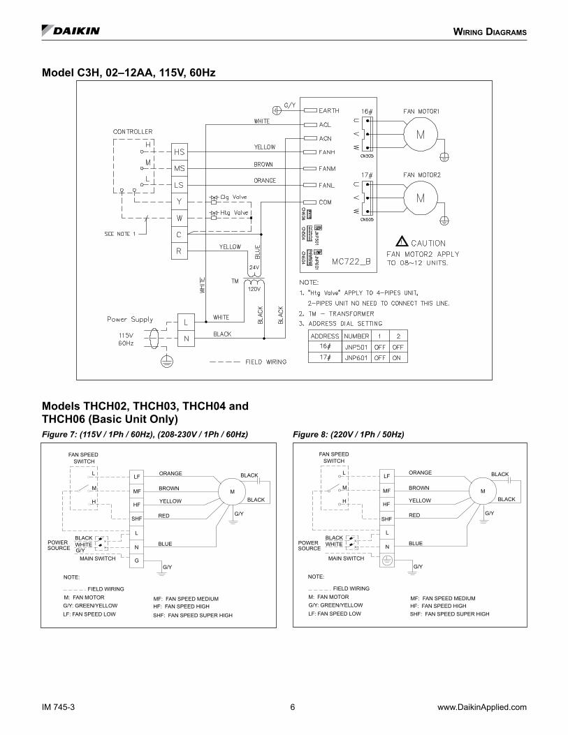
Model C3H, 02–12AA, 115V, 60Hz
!
www.DaikinApplied.com 7 IM 745-3
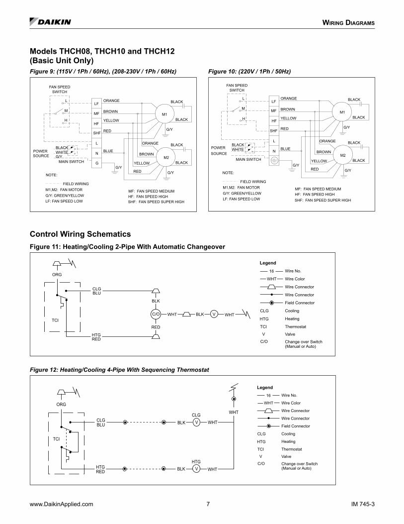
Models THCH08, THCH10 and THCH12 (Basic Unit Only)Figure 9: (115V / 1Ph / 60Hz), (208-230V / 1Ph / 60Hz)
H YELLOW
SHF: FAN SPEED SUPER HIGH
BLACKYELLOW
LF: FAN SPEED LOW
M1,M2: FAN MOTORFIELD WIRING
NOTE:
HF: FAN SPEED HIGHMF: FAN SPEED MEDIUM
G/YRED G/Y
BLUE
RED
L
SOURCEPOWER N
FAN SPEEDSWITCH
SHF
HF
ORANGE
BROWNM2
BLACK
G/Y
BLACK
ORANGE
BROWN
L
MMF
LF
M1
BLACK
MAIN SWITCH G
G/YWHITEBLACK
G/Y: GREEN/YELLOW
BLACK
G/Y: GREEN/YELLOW
FIELD WIRINGM1,M2: FAN MOTOR
LF: FAN SPEED LOW
NOTE:
POWERSOURCE
MAIN SWITCH
BLACKWHITE
MF: FAN SPEED MEDIUMHF: FAN SPEED HIGHSHF: FAN SPEED SUPER HIGH
M2
G/YRED
BLUEN
YELLOW
BROWN
G/Y
BLACK
SWITCHFAN SPEED
H
M
LLF
G/Y
L
REDSHF
ORANGE
MF
YELLOWHF
BROWNM1
BLACK
ORANGE BLACK
Figure 10: (220V / 1Ph / 50Hz)
H YELLOW
SHF: FAN SPEED SUPER HIGH
BLACKYELLOW
LF: FAN SPEED LOW
M1,M2: FAN MOTORFIELD WIRING
NOTE:
HF: FAN SPEED HIGHMF: FAN SPEED MEDIUM
G/YRED G/Y
BLUE
RED
L
SOURCEPOWER N
FAN SPEEDSWITCH
SHF
HF
ORANGE
BROWNM2
BLACK
G/Y
BLACK
ORANGE
BROWN
L
MMF
LF
M1
BLACK
MAIN SWITCH G
G/YWHITEBLACK
G/Y: GREEN/YELLOW
BLACK
G/Y: GREEN/YELLOW
FIELD WIRINGM1,M2: FAN MOTOR
LF: FAN SPEED LOW
NOTE:
POWERSOURCE
MAIN SWITCH
BLACKWHITE
MF: FAN SPEED MEDIUMHF: FAN SPEED HIGHSHF: FAN SPEED SUPER HIGH
M2
G/YRED
BLUEN
YELLOW
BROWN
G/Y
BLACK
SWITCHFAN SPEED
H
M
LLF
G/Y
L
REDSHF
ORANGE
MF
YELLOWHF
BROWNM1
BLACK
ORANGE BLACK
WIrIng DIagrams
Control Wiring SchematicsFigure 11: Heating/Cooling 2-Pipe With Automatic Changeover
WHT
16
CLGBLU
HTGRED
BLK
RED
WHTWHTTCI
ORG
C/O VHTG
CLG
TCI
V
C/O
Wire No.
Wire Color
Wire Connector
Wire Connector
Field Connector
Cooling
Heating
Thermostat
Valve
Change over Switch(Manual or Auto)
BLK
Legend
Figure 12: Heating/Cooling 4-Pipe With Sequencing Thermostat
CLGBLU
HTGRED
BLK
BLKHTG
CLG
WHT
WHT
WHT
TCI
ORG
V
V
WHT
16
HTG
CLG
TCI
V
C/O
Wire No.
Wire Color
Wire Connector
Wire Connector
Field Connector
Cooling
Heating
Thermostat
Valve
Change over Switch(Manual or Auto)
Legend
IM 745-3 8 www.DaikinApplied.com
DImensIonal Data
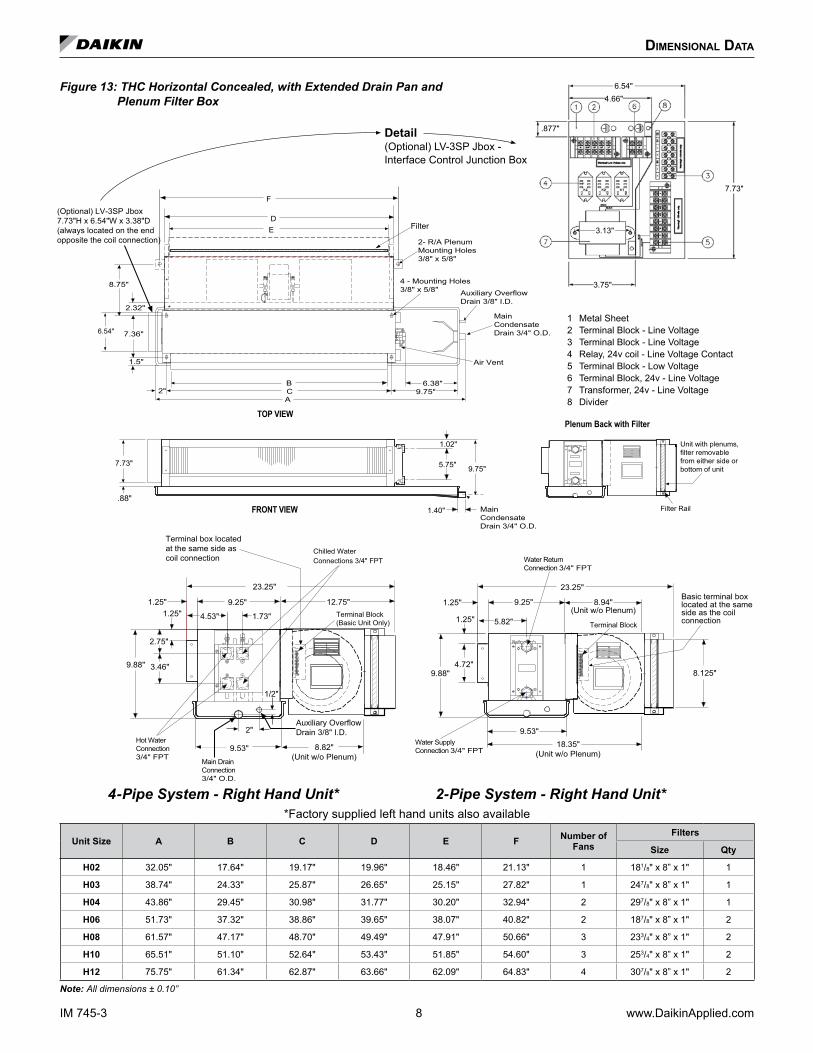
Figure 13: THC Horizontal Concealed, with Extended Drain Pan and Plenum Filter Box
Terminal Block(Basic Unit Only)
4.53"
1.25"
9.53"
Chilled Water Connections 3/4" FPT
9.88"
1.25"
5.82"
9.25"
23.25"
1.25"
4.72"
9.53"
Plenum Back with Filter
Filter Rail
Water Return Connection 3/4" FPT
Air Vent
FilterED
4 - Mounting Holes 3/8" x 5/8"
TOP VIEW
8.125"
2- R/A PlenumMounting Holes 3/8" x 5/8"
F
2"Auxiliary Overflow Drain 3/8" I.D.
Auxiliary OverflowDrain 3/8" I.D.
Basic terminal boxlocated at the sameside as the coil connection
Unit with plenums,filter removablefrom either side orbottom of unit
Terminal box locatedat the same side as coil connection
Main Condensate Drain 3/4" O.D.
1/2"
1.25"
23.25"
9.25"
9.88"
1.73"
2.75"
3.46"
2.32"
7.36"
6.38"
A9.75"
B
1.5"
C
1.02"
5.75" 9.75"
1.40"
12.75"
8.75"
2"
6.54"
7.73"
.88"FRONT VIEW Main
Condensate Drain 3/4" O.D.
Terminal Block
Water Supply Connection 3/4" FPT
Hot Water Connection 3/4" FPT
Main DrainConnection 3/4" O.D.
8.82"(Unit w/o Plenum)
18.35"(Unit w/o Plenum)
(Optional) LV-3SP Jbox7.73"H x 6.54"W x 3.38"D (always located on the end opposite the coil connection)
8.94"(Unit w/o Plenum)
Detail (Optional) LV-3SP Jbox - Interface Control Junction Box
7.73"
6.54"4.66"
.877"
3.75"
3.13"
1 Metal Sheet2 Terminal Block - Line Voltage3 Terminal Block - Line Voltage4 Relay, 24v coil - Line Voltage Contact5 Terminal Block - Low Voltage6 Terminal Block, 24v - Line Voltage7 Transformer, 24v - Line Voltage8 Divider
4-Pipe System - Right Hand Unit* 2-Pipe System - Right Hand Unit**Factory supplied left hand units also available
Unit Size A B C D E F Number of Fans
Filters
Size Qty
H02 32.05" 17.64" 19.17" 19.96" 18.46" 21.13" 1 181/8" x 8” x 1" 1
H03 38.74" 24.33" 25.87" 26.65" 25.15" 27.82" 1 247/8" x 8” x 1" 1
H04 43.86" 29.45" 30.98" 31.77" 30.20" 32.94" 2 297/8" x 8” x 1" 1
H06 51.73" 37.32" 38.86" 39.65" 38.07" 40.82" 2 187/8" x 8” x 1" 2
H08 61.57" 47.17" 48.70" 49.49" 47.91" 50.66" 3 233/4" x 8” x 1" 2
H10 65.51" 51.10" 52.64" 53.43" 51.85" 54.60" 3 253/4" x 8” x 1" 2
H12 75.75" 61.34" 62.87" 63.66" 62.09" 64.83" 4 307/8" x 8” x 1" 2
Note: All dimensions ± 0.10”
maIntenanCe
GeneralA good general maintenance plan will avoid performance loss and unexpected shut-down of the equipment.A dirty filter reduces air flow as well as unit performance. Changing or cleaning the filter is very important. Check the filter monthly and replace or clean as required.Coils should be cleaned of dust, dirt and lint with compressed air or water. They can be vacuumed or brushed with a soft brush.
CAUTIONWater coils exposed to freezing temperatures should be drained or anti-freeze should be added to the water circuit to avoid freezing.
Monthly intervals1 . Inspect and clean the condensate drain pan to help avoid
clogging of drainage by dirt, dust, etc. Inspect drainage piping for proper condensate flow.
2 . Check and clean the coil. Clean the coil with a low pressure water jet or low pressure air.
3 . Clean and tighten all the wiring connections.
www.DaikinApplied.com 9 IM 745-3
troubleshootIng
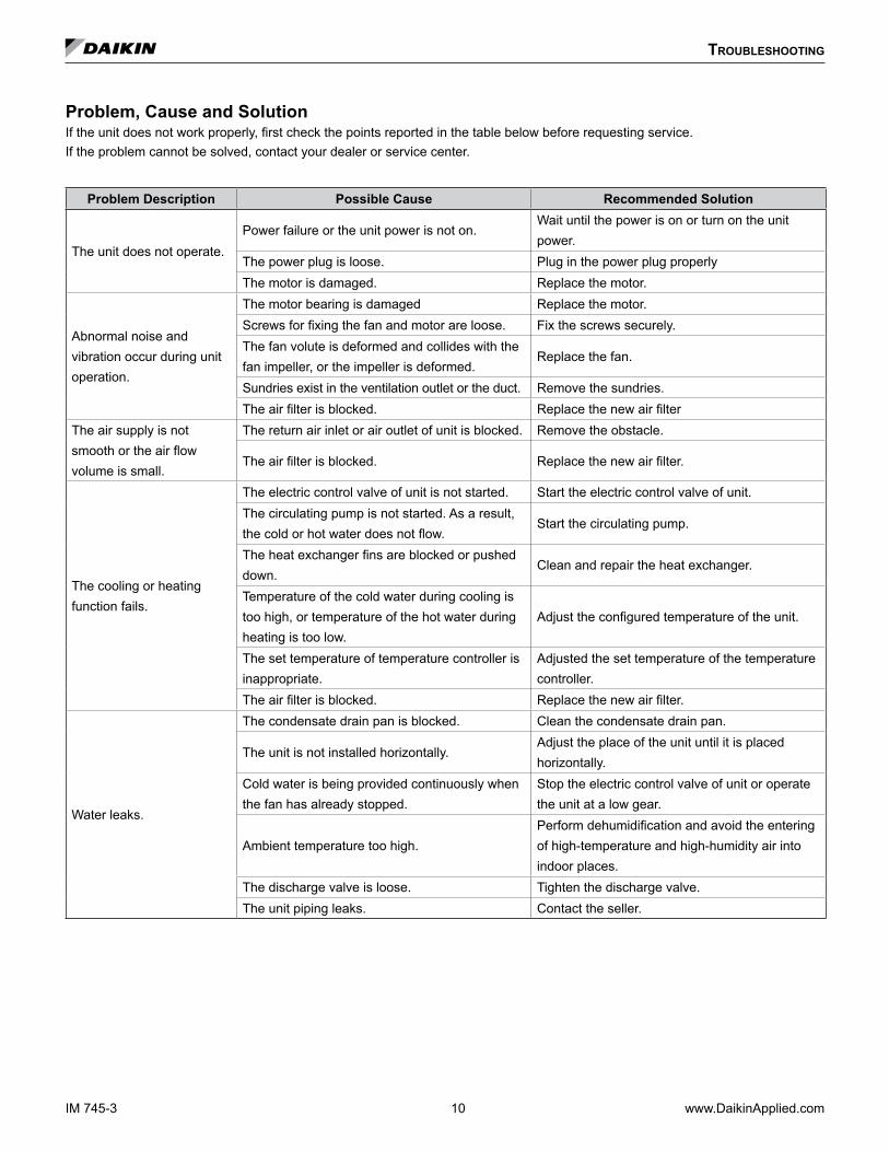
Problem, Cause and SolutionIf the unit does not work properly, first check the points reported in the table below before requesting service.If the problem cannot be solved, contact your dealer or service center.
Problem Description Possible Cause Recommended Solution
The unit does not operate.Power failure or the unit power is not on.
Wait until the power is on or turn on the unit power.
The power plug is loose. Plug in the power plug properlyThe motor is damaged. Replace the motor.
Abnormal noise and vibration occur during unit operation.
The motor bearing is damaged Replace the motor.Screws for fixing the fan and motor are loose. Fix the screws securely.The fan volute is deformed and collides with the fan impeller, or the impeller is deformed.
Replace the fan.
Sundries exist in the ventilation outlet or the duct. Remove the sundries.The air filter is blocked. Replace the new air filter
The air supply is not smooth or the air flow volume is small.
The return air inlet or air outlet of unit is blocked. Remove the obstacle.
The air filter is blocked. Replace the new air filter.
The cooling or heating function fails.
The electric control valve of unit is not started. Start the electric control valve of unit.The circulating pump is not started. As a result, the cold or hot water does not flow.
Start the circulating pump.
The heat exchanger fins are blocked or pushed down.
Clean and repair the heat exchanger.
Temperature of the cold water during cooling is too high, or temperature of the hot water during heating is too low.
Adjust the configured temperature of the unit.
The set temperature of temperature controller is inappropriate.
Adjusted the set temperature of the temperature controller.
The air filter is blocked. Replace the new air filter.
Water leaks.
The condensate drain pan is blocked. Clean the condensate drain pan.
The unit is not installed horizontally.Adjust the place of the unit until it is placed horizontally.
Cold water is being provided continuously when the fan has already stopped.
Stop the electric control valve of unit or operate the unit at a low gear.
Ambient temperature too high.Perform dehumidification and avoid the entering of high-temperature and high-humidity air into indoor places.
The discharge valve is loose. Tighten the discharge valve.The unit piping leaks. Contact the seller.
IM 745-3 10 www.DaikinApplied.com
troubleshootIng
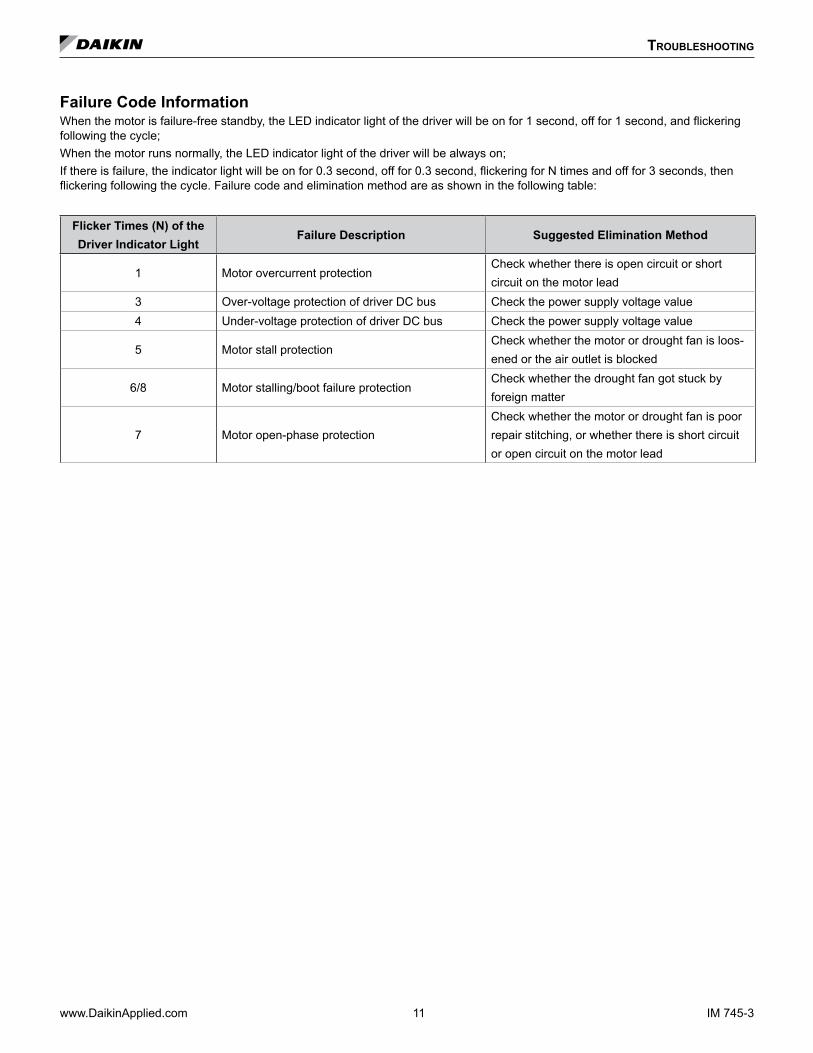
Failure Code InformationWhen the motor is failure-free standby, the LED indicator light of the driver will be on for 1 second, off for 1 second, and flickering following the cycle;When the motor runs normally, the LED indicator light of the driver will be always on;If there is failure, the indicator light will be on for 0.3 second, off for 0.3 second, flickering for N times and off for 3 seconds, then flickering following the cycle. Failure code and elimination method are as shown in the following table:
Flicker Times (N) of theDriver Indicator Light
Failure Description Suggested Elimination Method
1 Motor overcurrent protectionCheck whether there is open circuit or short circuit on the motor lead
3 Over-voltage protection of driver DC bus Check the power supply voltage value4 Under-voltage protection of driver DC bus Check the power supply voltage value
5 Motor stall protectionCheck whether the motor or drought fan is loos-ened or the air outlet is blocked
6/8 Motor stalling/boot failure protectionCheck whether the drought fan got stuck by foreign matter
7 Motor open-phase protectionCheck whether the motor or drought fan is poor repair stitching, or whether there is short circuit or open circuit on the motor lead
www.DaikinApplied.com 11 IM 745-3
IM 745-3 ©2018 Daikin Applied (10/18) | (800) 432–1342 | www.DaikinApplied.com
Daikin Applied Training and Development
Now that you have made an investment in modern, efficient Daikin equipment, its care should be a high priority. For training information on all Daikin HVAC products, please visit us at www.DaikinApplied.com and click on Training, or call 540-248-9646 and ask for the Training Department.
Warranty
All Daikin equipment is sold pursuant to its standard terms and conditions of sale, including Limited Product Warranty. Consult your local Daikin Applied representative for warranty details. Refer to Form 933-430285Y. To find your local Daikin Applied representative, go to www.DaikinApplied.com.
Aftermarket Services
To find your local parts office, visit www.DaikinApplied.com or call 800-37PARTS (800-377-2787). To find your local service office, visit www.DaikinApplied.com or call 800-432-1342.
This document contains the most current product information as of this printing. For the most up-to-date product information, please go to www.DaikinApplied.com.
Products manufactured in an ISO Certified Facility.