Embed Size (px)
Citation preview
Installation and Maintenance Manual forSPANCO® Freestanding Workstation Bridge Cranes
Manual No. 103-0011REV. 1/10
ISO 9001 REGISTERED© SPANCO, Inc.
Design Factors............................................................................................................ 3
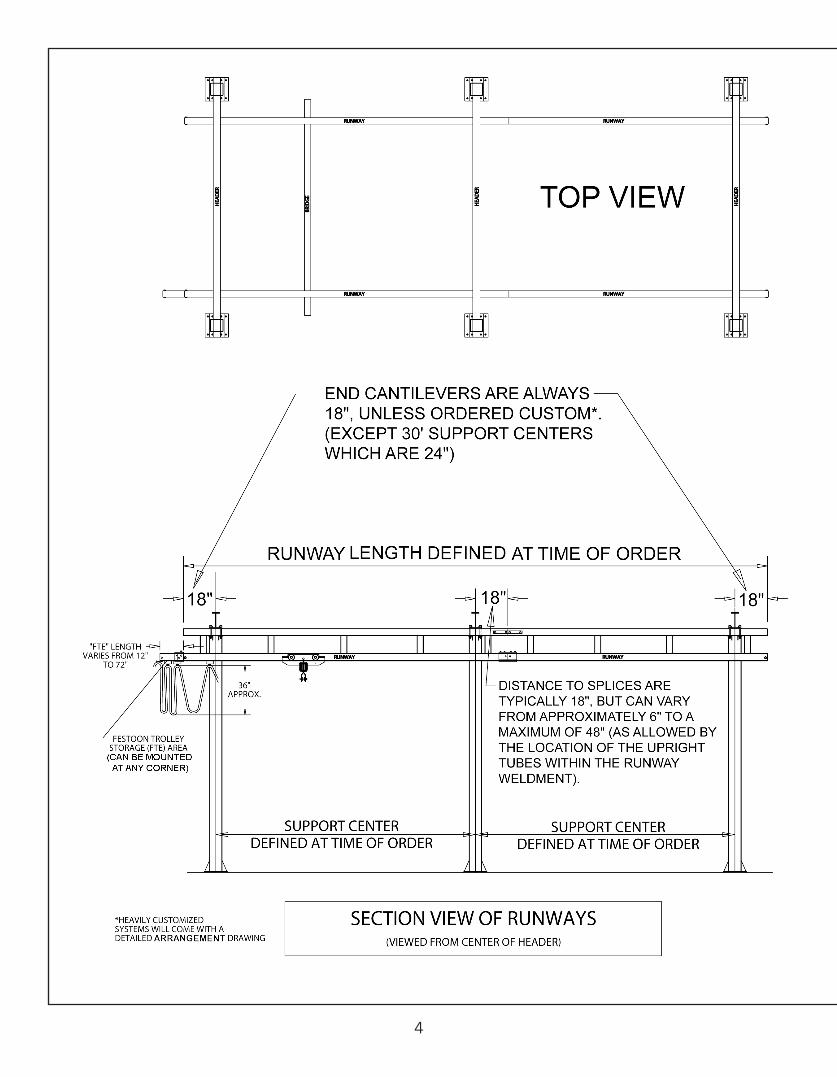
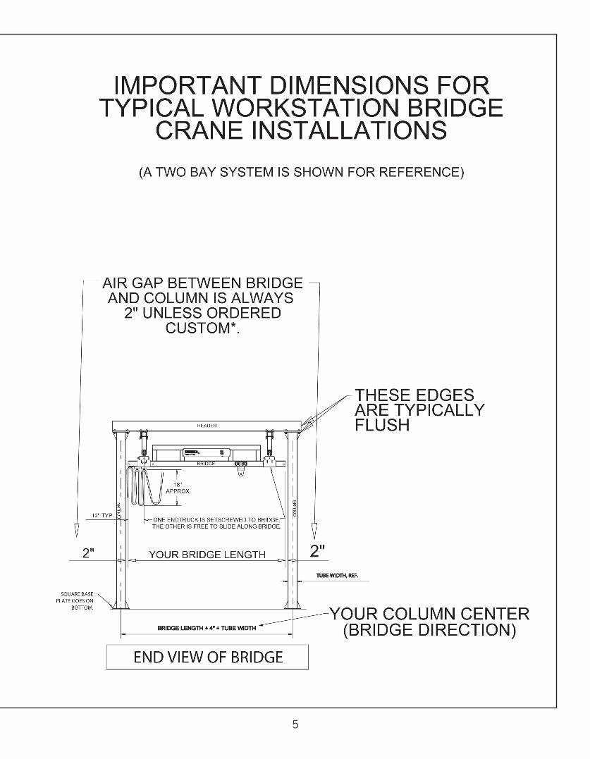
Important Dimensions for Typical Workstation Bridge Crane Installations.......................4-5
Preparation.................................................................................................................6
Column and Header Installation....................................................................................7
Lindapter Sizing Chart................................................................................................. 8
Runway Installation................................................................................................ 9-10
Splice Installation..................................................................................................... 11
Bridge End Truck Installation..................................................................................... 12
Runway End Stop Installation.....................................................................................13
Festoon Track Extension Installation, 400 Series..........................................................13
Festoon Track Extension Installation, 500-900 Series...................................................14
Runway Festoon Installation.......................................................................................15
Hoist Trolley and Bridge Festoon Installation................................................................16
Hoist Installation.......................................................................................................17
Service Connections.................................................................................................. 18
Design Factors.......................................................................................................... 19
Appendix Pages
AP-1 Header to Header Connections..................................................................... 20
AP-2 Plain Track Reverse Flush Mount..................................................................21
AP-3 Runway Hanger Top Mount.......................................................................... 22
AP-4 Adjustable Method of Column Anchorage...................................................... 23
Warranty and Service Policy........................................................................................24
TABLE OF CONTENTS
This equipment, used as a crane, is NOT, in any way, designed for lifting,supporting, or transporting humans. Failure to follow specified loadlimitations can result in serious bodily injury or death.rWARNING!
2
3
DESIGN FACTORS
Nameplate bridge capacity represents the rated load on the hoist hook. The load rating of ahoist shall not exceed the bridge rating. SPANCO’s design includes an allowance of 15% ofnameplate capacity for dead weight of the trolley and hoist. An additional 25% ofnameplate capacity is also included for impact.
SEISMIC DESIGN RATING
All SPANCO workstation bridge cranes meet design requirements for installation and use inseismic zone 4, of the uniform building code, the worst earthquake prone areas in NorthAmerica.
SERVICE FACTOR
All SPANCO workstation cranes are designed for frequent usage (heavy service) as defined:
• System or equipment is used where operational time is up to 100% of the work periodand lifted load is at 50% or below rated capacity.
• System or equipment is used where operational time is less than 50% of work period and lifted load is greater than 50% of rated capacity.
• Applications involving vacuums, magnets, or other high impact lifters are considered severe usage and require special design considerations. Please contact factory for special design pricing.
• Consult factory for usage other than moderate and all instances of high cycle rates or high impact applications such as high speed air or electric hoists, vacuum lifters, or magnets.
4
5
6
PREPARATION
1. Before starting the installation, check the material list to be sure you have received all parts. The anchor bolts for the support columns are not included. Four, 13/16” diameter holes are provided for anchor bolts, furnished by others, as required. Sway bracing is recommended and is also furnished by others, as required.
COLUMN AND HEADER INSTALLATION
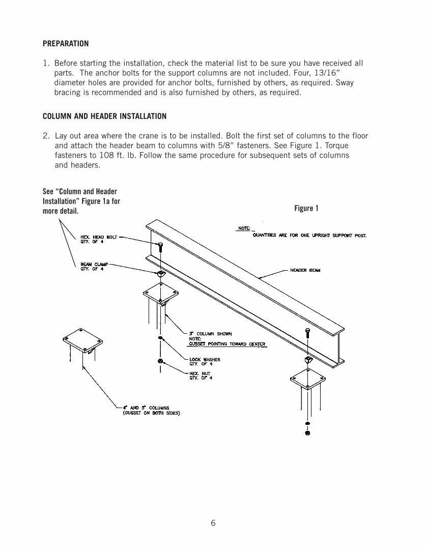
2. Lay out area where the crane is to be installed. Bolt the first set of columns to the floor and attach the header beam to columns with 5/8” fasteners. See Figure 1. Torque fasteners to 108 ft. lb. Follow the same procedure for subsequent sets of columns and headers.
See “Column and HeaderInstallation” Figure 1a formore detail. Figure 1
7
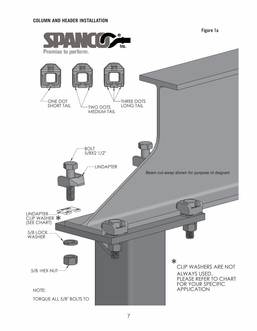
Figure 1a
COLUMN AND HEADER INSTALLATION
Beam cut-away shown for purpose of diagram
8
9
QUANTITIES ARE FOR ONE SUPPORT HANGER.
NOTE
HEX. HEAD BOLTQTY. OF 4
BEAM CLAMPQTY. OF 4
QTY. OF 1CLAMP PLATE
CLAMP ANGLEQTY. OF 2
QTY. OF 4LOCK WASHER
HEADER BEAMRUNWAY TRACK
HEX. NUTQTY. OF 4
COLUMN
RUNWAY SUPPORT CENTER
WARNING:
DO NOT LOCATE SPLICE JOINTS MORE THAN48 INCHES FROM THE RUNWAY SUPPORT CENTERS.
DO NOT CANTILEVER THE RUNWAY TRACK ENDS MORETHAN 18 INCHES BEYOND THE RUNWAY SUPPORT CENTERS(NOT INCLUDING FESTOON ST RO AGE AREA).
WARNING LABELON BOTH SIDESOF BOTH ENDS.
DO NOT OPERATE CRANE WITHOUTEND STOP BOLTS FIRMLY SECUREDIN PLACE ON EACH END OF THEBRIDGE CRANE TRACK AND ONEACH END OF EACH RUNWAY TRACK.
RUNNING OUT OF THE TRACKTO PREVENT TROLLEY/END TRUCK
P/N 53-0047
!
Figure 2
RUNWAY INSTALLATION
3. Using caution not to disturb the columns, raise the runway track into position and clamp it to the header beams with 5/8” fasteners, see Figure 2. Torque fasteners to 108 ft. lbs. Do not cantilever the ends of the runway tracks more than 18” beyond thesupport centers. The center of runway is located approximately 14” from the inside edge of the support column. OSHA regulations require a minimum clearance of 2” fromthe end of the bridge track to the face of the support columns or other obstructions.
See “Typical Runway to Header Connection”Figure 2a for more detail
10
Figure 2aTYPICAL RUNWAY TO HEADER CONNECTION
11
SPLICE INSTALLATION
4. If your system has more than one section (length) of runway track, each additional section is installed in the same manner as the first, with the addition of a splice joint assembly.
The track splice joint is made using a sleeve with a total of eight set screws threaded into the top and both sides. Slide the sleeve over the end of the first runway track, thenbutt the second runway track against the first. Center the sleeve over the joint. The two center top set screws should be tightened slightly to push the tracks against the base ofthe sleeve so that the two bottom surfaces of the track are even. Adjust the side set screws so that the track slots are aligned and there is a smooth transition from one track to the other, see Figure 3. Tighten all top set screws then side set screws for correct track alignment.
Trussed runway splice joints also include two splice plates and four, 1/2 inch bolts with nuts. Install the splice plates to connect the ends of the truss top tubes with the four through bolts provided. Torque through bolts to 50 ft. lb., see Figure 3.
Trussed Runway: Splice joints should be within 48” of a support hanger as shown in Figure 3. Refer to Figure 4, page 12, for splice joint track alignment.
Figure 3
12
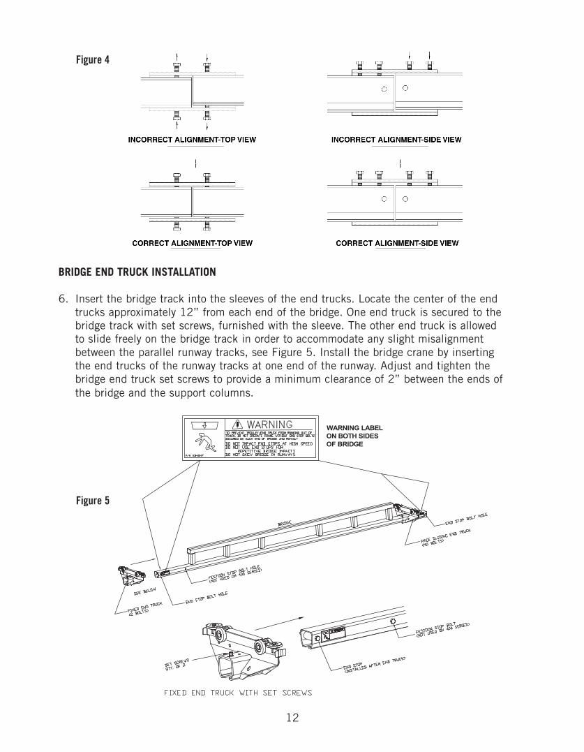
Figure 4
BRIDGE END TRUCK INSTALLATION
6. Insert the bridge track into the sleeves of the end trucks. Locate the center of the end trucks approximately 12” from each end of the bridge. One end truck is secured to the bridge track with set screws, furnished with the sleeve. The other end truck is allowed to slide freely on the bridge track in order to accommodate any slight misalignment between the parallel runway tracks, see Figure 5. Install the bridge crane by inserting the end trucks of the runway tracks at one end of the runway. Adjust and tighten the bridge end truck set screws to provide a minimum clearance of 2” between the ends of the bridge and the support columns.
Figure 5
13
RUNWAY END STOP INSTALLATION
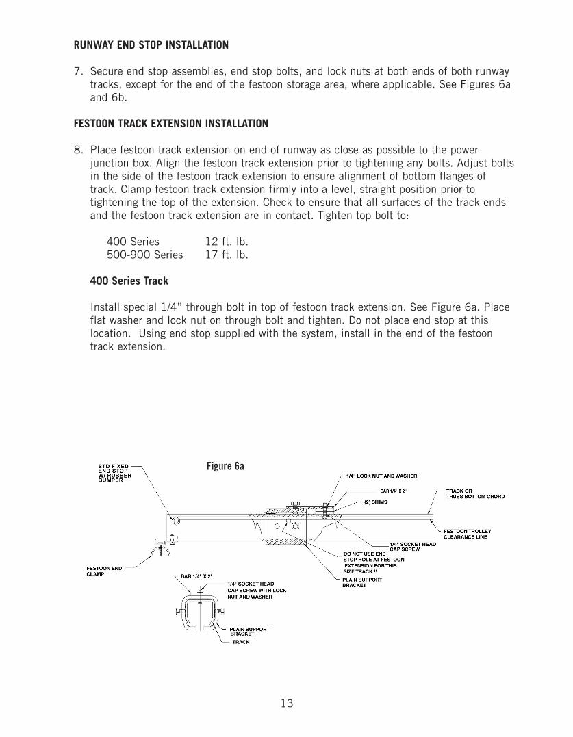
7. Secure end stop assemblies, end stop bolts, and lock nuts at both ends of both runway tracks, except for the end of the festoon storage area, where applicable. See Figures 6a and 6b.
FESTOON TRACK EXTENSION INSTALLATION
8. Place festoon track extension on end of runway as close as possible to the power junction box. Align the festoon track extension prior to tightening any bolts. Adjust boltsin the side of the festoon track extension to ensure alignment of bottom flanges of track. Clamp festoon track extension firmly into a level, straight position prior to tightening the top of the extension. Check to ensure that all surfaces of the track ends and the festoon track extension are in contact. Tighten top bolt to:
400 Series 12 ft. lb.500-900 Series 17 ft. lb.
400 Series Track
Install special 1/4” through bolt in top of festoon track extension. See Figure 6a. Place flat washer and lock nut on through bolt and tighten. Do not place end stop at this location. Using end stop supplied with the system, install in the end of the festoon track extension.
Figure 6a
14
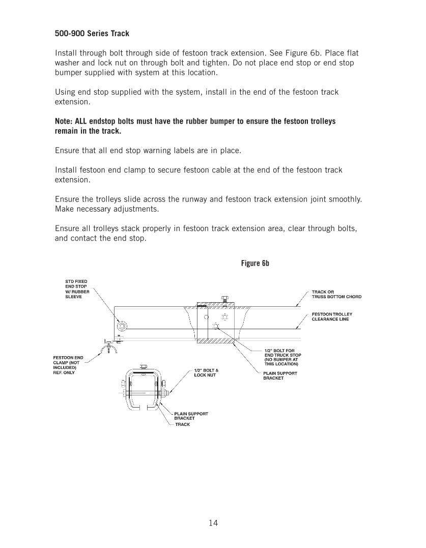
500-900 Series Track
Install through bolt through side of festoon track extension. See Figure 6b. Place flat washer and lock nut on through bolt and tighten. Do not place end stop or end stop bumper supplied with system at this location.
Using end stop supplied with the system, install in the end of the festoon track extension.
Note: ALL endstop bolts must have the rubber bumper to ensure the festoon trolleys remain in the track.
Ensure that all end stop warning labels are in place.
Install festoon end clamp to secure festoon cable at the end of the festoon track extension.
Ensure the trolleys slide across the runway and festoon track extension joint smoothly. Make necessary adjustments.
Ensure all trolleys stack properly in festoon track extension area, clear through bolts, and contact the end stop.
Figure 6b
15
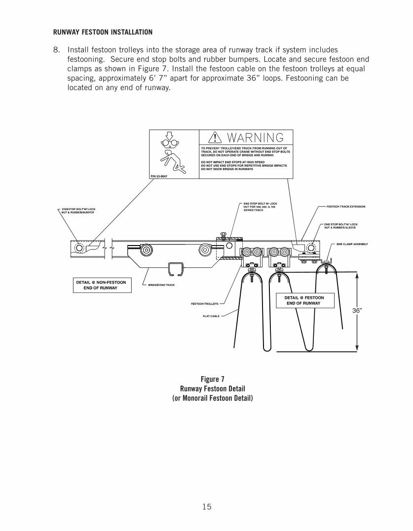
RUNWAY FESTOON INSTALLATION
8. Install festoon trolleys into the storage area of runway track if system includes festooning. Secure end stop bolts and rubber bumpers. Locate and secure festoon end clamps as shown in Figure 7. Install the festoon cable on the festoon trolleys at equal spacing, approximately 6’ 7” apart for approximate 36” loops. Festooning can be located on any end of runway.
!TO PREVENT TROLLEY/END TRUCK FROM RUNNING OUT OFTRACK, DO NOT OPERATE CRANE WITHOUT END STOP BOLTSSECURED ON EACH END OF BRIDGE AND RUNWAY.
DO NOT IMPACT END STOPS AT HIGH SPEEDDO NOT USE END STOPS FOR REPETITIVE BRIDGE IMPACTSDO NOT SKEW BRIDGE IN RUNWAYS
Figure 7Runway Festoon Detail
(or Monorail Festoon Detail)
36”
16
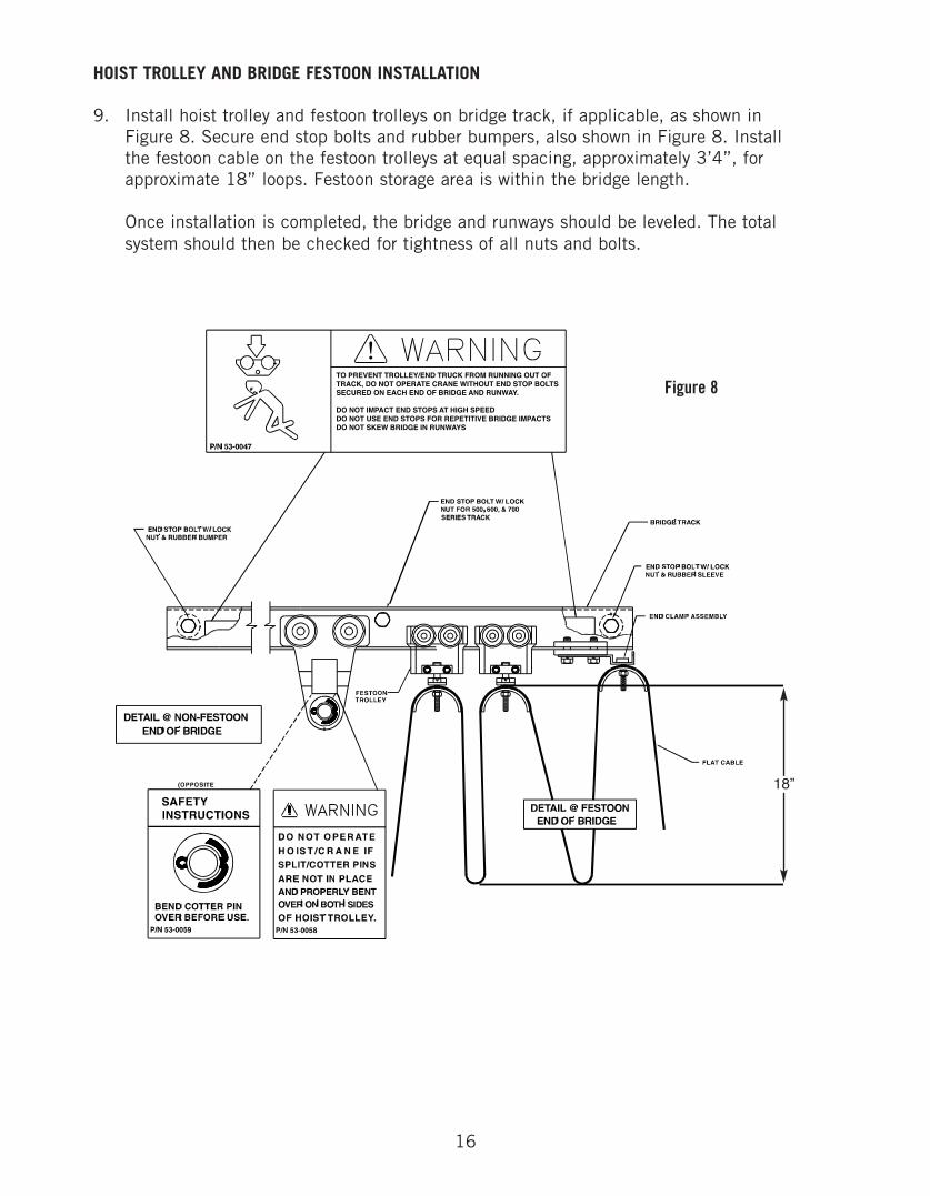
HOIST TROLLEY AND BRIDGE FESTOON INSTALLATION
9. Install hoist trolley and festoon trolleys on bridge track, if applicable, as shown in Figure 8. Secure end stop bolts and rubber bumpers, also shown in Figure 8. Install the festoon cable on the festoon trolleys at equal spacing, approximately 3’4”, for approximate 18” loops. Festoon storage area is within the bridge length.
Once installation is completed, the bridge and runways should be leveled. The total system should then be checked for tightness of all nuts and bolts.
!TO PREVENT TROLLEY/END TRUCK FROM RUNNING OUT OFTRACK, DO NOT OPERATE CRANE WITHOUT END STOP BOLTSSECURED ON EACH END OF BRIDGE AND RUNWAY.
DO NOT IMPACT END STOPS AT HIGH SPEEDDO NOT USE END STOPS FOR REPETITIVE BRIDGE IMPACTSDO NOT SKEW BRIDGE IN RUNWAYS
Figure 8
18”
P/N 53-0058
DO NOT OPERATEH O IS T /C R A N E IFSPLIT/COTTER PINSARE NOT IN PLACEAND PROPERLY BENTOVER ON BOTH SIDESOF HOIST TROLLEY.
OPPOSITE SIDE
P/N 53-0059
!SAFETYINSTRUCTIONS
BEND COTTER PINOVER BEFORE USE.
HOOK MUST BECENTERED ONTROLLEY PIN.
17
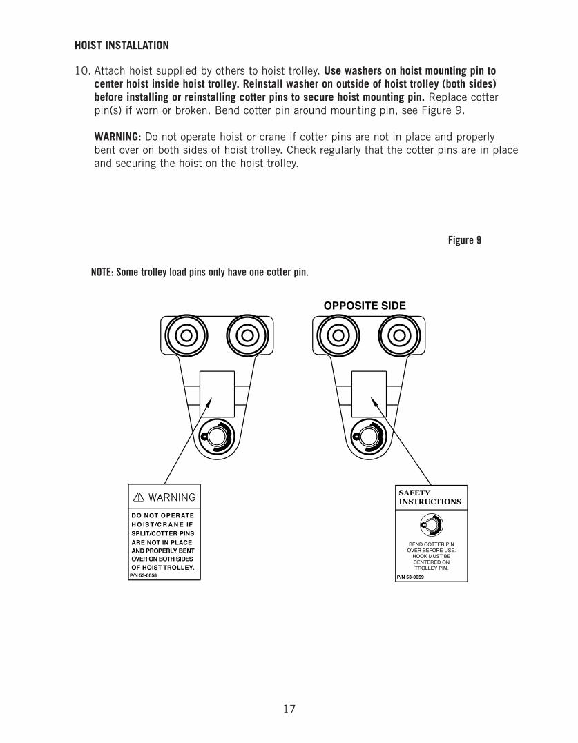
HOIST INSTALLATION
10. Attach hoist supplied by others to hoist trolley. Use washers on hoist mounting pin to center hoist inside hoist trolley. Reinstall washer on outside of hoist trolley (both sides) before installing or reinstalling cotter pins to secure hoist mounting pin. Replace cotter pin(s) if worn or broken. Bend cotter pin around mounting pin, see Figure 9.
WARNING: Do not operate hoist or crane if cotter pins are not in place and properly bent over on both sides of hoist trolley. Check regularly that the cotter pins are in placeand securing the hoist on the hoist trolley.
Figure 9
NOTE: Some trolley load pins only have one cotter pin.
18
SERVICE CONNECTIONS
11. Where applicable, follow the supplemental circuit diagrams to make service connections, such as electrical power. Make sure services are not energized while making any connections and that they match the specified supply on the circuit diagram.
WARNING, SAFETY, OR CAPACITY LABELS
12. If at any time these labels are lost, stolen, removed or become illegible, contact SPANCO at 800-869-2080 for free replacements. Please order by part number on the label or by the facsimiles in this manual.
ACCEPTANCE TEST
After the workstation crane or monorail system has been installed, OSHA requires an acceptance test before operating and also after any modifications. This acceptance test should be performed by an authorized dealer or installer.
IMPORTANT MAINTENANCE INFORMATION
At the end of the first month after a new installation, an inspection of the system should be performed. All nuts, bolts and screws should be checked for tightness. All end stops, cotter pins, and hoist trolleys should be checked for abnormal wear or breakage. Check all track splices for alignment and that end trucks and festoon trolleystravel smoothly through the joints. Also, check that all festoon cables and/or hoses are securely clamped to the festoon trolleys and end clamps. Adjust as necessary.
Thereafter, a complete inspection of all fasteners and connections should be performedannually or every 2000 hrs., which ever comes first. It is important to note that every system application and use will be different, therefore some conditions of use could require more frequent inspection. Examples of suchvconditions might be two or three shift operations, high, repetitive, fast movement of the crane, or frequent crashing of the crane end trucks or trolley into the end stops.
It is expected that every time an operator uses a workstation crane or monorail system, they visually inspect the system before using it and note any unusual or abnormal operation of the system while using it. Meticulous, careful operation of the system will help minimize system maintenance.
ITEM CHECK
nuts, bolts, screws..................... tightnessendstops, cotter pins,hoist trolley(s),track, and supports.................... abnormal wear or breakagetrack splices.............................. alignment and smooth travel through jointsfestoon cable/hoses.................... clamped securely, abnormal wear or breakage
19
DESIGN FACTORS
Nameplate bridge capacity represents the rated load on the hoist hook. The load rating of a hoist shallnot exceed the bridge rating. SPANCO’s design includes an allowance of 15% of nameplate capacity fordead weight of the trolley and hoist. An additional 25% of nameplate capacity is also included forimpact.
SEISMIC DESIGN RATING
All SPANCO workstation bridge cranes meet design requirements for installation and use in seismic zone4, of the uniform building code, the worst earthquake prone areas in North America.
SERVICE FACTOR
All SPANCO workstation cranes are designed for frequent usage (heavy service) as defined:
• System or equipment is used where operational time is up to 100% of the work period and lifted load is at 50% or below rated capacity.
• System or equipment is used where operational time is less than 50% of work period and lifted load is greater than 50% of rated capacity.
• Applications involving vacuums, magnets, or other high impact lifters are considered severe usage and require special design considerations. Please contact factory for special design pricing.
• Consult factory for usage other than moderate and all instances of high cycle rates or high impact applications such as high speed air or electric hoists, vacuum lifters, or magnets.
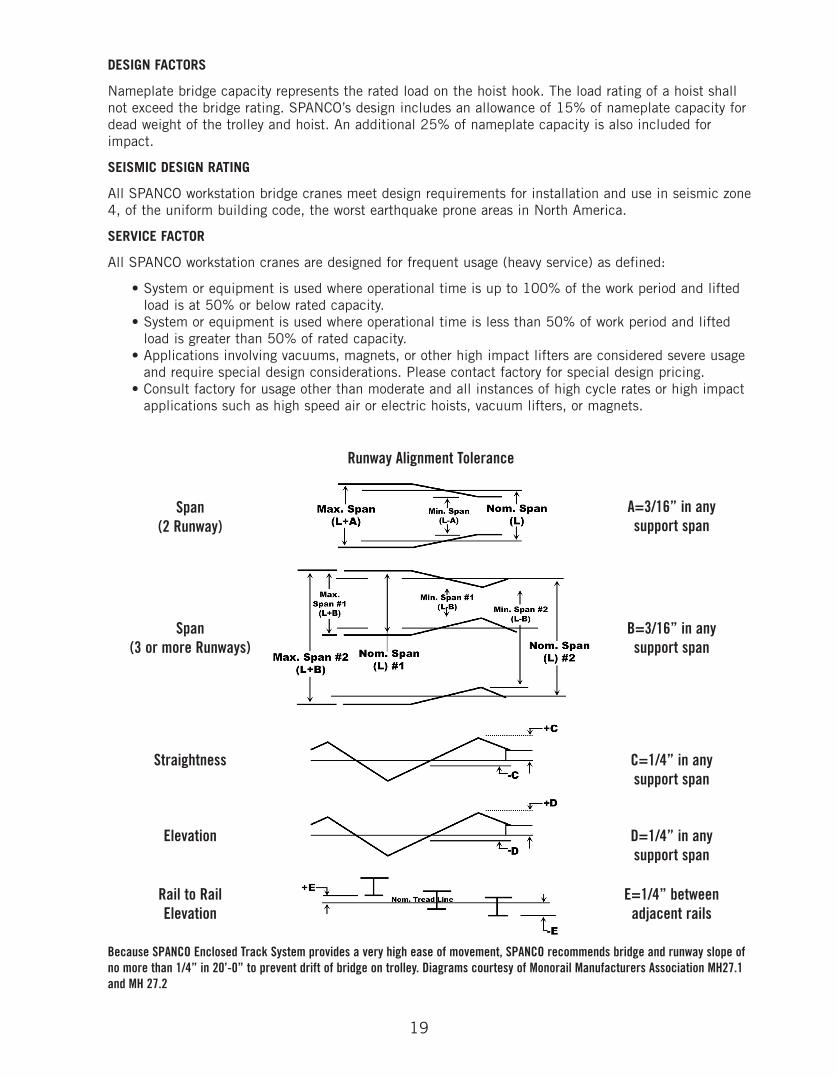
Runway Alignment Tolerance
Span(2 Runway)
A=3/16” in anysupport span
Span(3 or more Runways)
B=3/16” in anysupport span
Straightness C=1/4” in anysupport span
Elevation D=1/4” in anysupport span
Rail to RailElevation
E=1/4” betweenadjacent rails
Because SPANCO Enclosed Track System provides a very high ease of movement, SPANCO recommends bridge and runway slope ofno more than 1/4” in 20’-0” to prevent drift of bridge on trolley. Diagrams courtesy of Monorail Manufacturers Association MH27.1and MH 27.2
20
FLAT TOP LINDAPTER USEDON THE SAME SIDE
AP-1
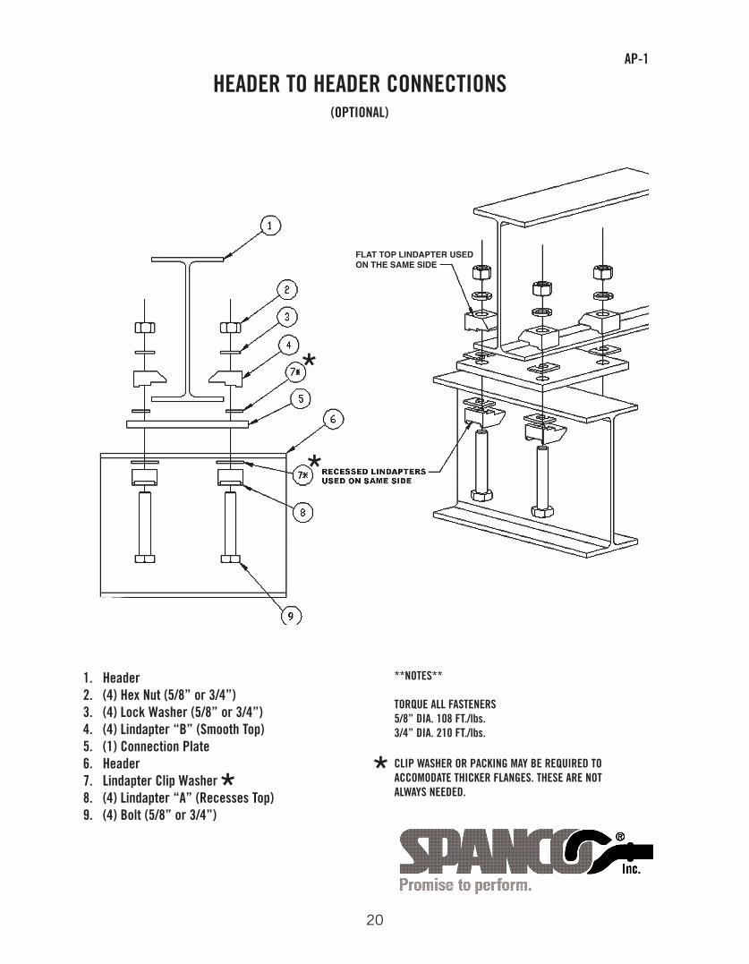
HEADER TO HEADER CONNECTIONS(OPTIONAL)
1. Header2. (4) Hex Nut (5/8” or 3/4”)3. (4) Lock Washer (5/8” or 3/4”)4. (4) Lindapter “B” (Smooth Top)5. (1) Connection Plate6. Header7. Lindapter Clip Washer 8. (4) Lindapter “A” (Recesses Top)9. (4) Bolt (5/8” or 3/4”)
**NOTES**
TORQUE ALL FASTENERS5/8” DIA. 108 FT./lbs.3/4” DIA. 210 FT./lbs.
CLIP WASHER OR PACKING MAY BE REQUIRED TOACCOMODATE THICKER FLANGES. THESE ARE NOTALWAYS NEEDED.* *
*
*
21
AP-2
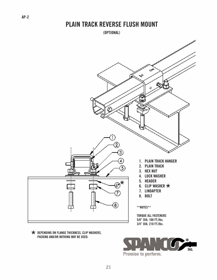
PLAIN TRACK REVERSE FLUSH MOUNT
1. PLAIN TRACK HANGER2. PLAIN TRACK3. HEX NUT4. LOCK WASHER5. HEADER 6. CLIP WASHER7. LINDAPTER8. BOLT
(OPTIONAL)
**NOTES**
TORQUE ALL FASTENERS5/8” DIA. 108 FT./lbs.3/4” DIA. 210 FT./lbs.
DEPENDING ON FLANGE THICKNESS, CLIP WASHERS,PACKING AND/OR NOTHING MAY BE USED.*
**
22
AP-3
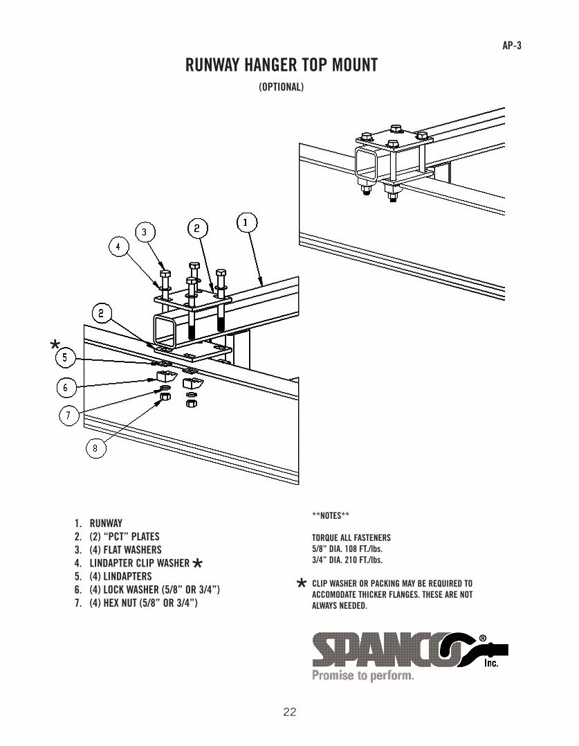
RUNWAY HANGER TOP MOUNT
1. RUNWAY2. (2) “PCT” PLATES 3. (4) FLAT WASHERS4. LINDAPTER CLIP WASHER5. (4) LINDAPTERS6. (4) LOCK WASHER (5/8” OR 3/4”)7. (4) HEX NUT (5/8” OR 3/4”)
(OPTIONAL)
**NOTES**
TORQUE ALL FASTENERS5/8” DIA. 108 FT./lbs.3/4” DIA. 210 FT./lbs.
CLIP WASHER OR PACKING MAY BE REQUIRED TOACCOMODATE THICKER FLANGES. THESE ARE NOTALWAYS NEEDED.
**
*
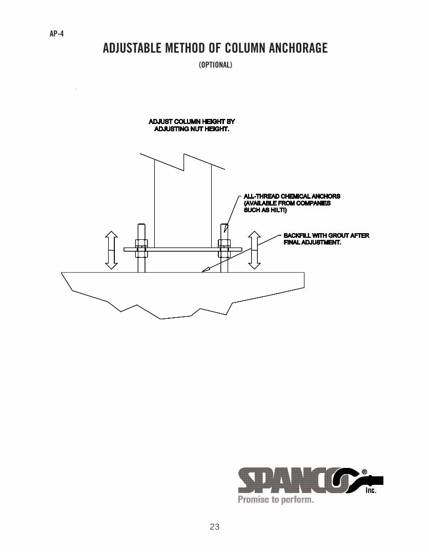
ADJUSTABLE METHOD OF COLUMN ANCHORAGE(OPTIONAL)
AP-4
23
24
FIVE-YEAR EQUIPMENT WARRANTY
SPANCO offers this Equipment Warranty (the “Warranty”) on the following equipment:
• Manually propelled Free Standing and Ceiling Mounted Workstation Bridge Cranes.• Manually propelled Monorails.• Manually propelled ALU-TRACK Bridge Cranes and Monorails.• Manually rotated Enclosed Track and I-Beam Jib Cranes.• Manually propelled Gantries.• Manually propelled Articulating Jib Cranes.• ALL motorized SPANCO products come with a one year warranty on drive components.
SPANCO warrants the Equipment and wearable end truck and trolley wheels only, to be free from defects in material and
workmanship for a period of five (5) years or 10,000 hours (whichever occurs first), commencing on the date of shipment to the first
retail purchaser (“Purchaser”). This Warranty does not extend to Equipment which has been subject to misuse, use in excess of rated
capacity, negligent operation, use beyond SPANCO's published service factors, improper installation or maintenance, and does not
apply to any Equipment which has been repaired or altered without SPANCO's written authorization. Written notice of any claimed
defect must be given to SPANCO within thirty (30) days after such defect is discovered. SPANCO's obligation, and Purchaser's sole
remedy under this Warranty is limited to, at SPANCO's discretion, the replacement or repair of the Equipment at SPANCO's factory or
at a location approved by SPANCO. Purchaser is responsible for all freight and transportation costs relating to the repair or
replacement of the Equipment. THE FOREGOING WARRANTY IS EXPRESSLY IN LIEU OF ALL OTHER WARRANTIES WHATSOEVER
WHETHER EXPRESS, IMPLIED, OR STATUTORY. SELLER MAKES NO WARRANTY AS TO THE MERCHANTABILITY OR FITNESS FOR
A PARTICULAR PURPOSE OF THE EQUIPMENT AND MAKES NO OTHER WARRANTY, EITHER EXPRESS OR IMPLIED. SPANCO shall
not be liable, under any circumstances, for any indirect, special or consequential damages including, but not limited to, lost profits,
increased operating costs or loss of production. This Warranty shall not extend to any components or accessories not manufactured by
SPANCO (such as casters), and Purchaser's remedy for such components and accessories shall be determined by the terms and
conditions of any warranty provided by the manufacturer of such components and accessories.
SERVICE POLICY
1. Obtain as much information as possible concerning the problem through personal observation by yourself or other authorized personnel familiar with the job and equipment: include model, serial and/or part numbers, voltages, speeds and any other special identifying features. Be prepared to discuss the situation in detail.
2. All authorized labor charges will be based on straight time. Hourly rates, estimated man hours, and not to exceed total dollar amount required for corrections are to be agreed upon before authorization is given. There will be no allowances for overtime except in dire emergencies and then only with prior approval.
3. A verbal agreement may be reached immediately on both the method of correction and the approximate cost. A warranty authorization number will be assigned for the specific incident. A confirming written authorization will be forwarded to the distributor.
4. The distributor must send an itemized invoice, showing our release number or invoice number and warranty authorization number after authorized corrections have been made. A credit memo will be issued by accounting after the invoice has been received and approved. Warranty charges ARE NOT to be deducted from outstanding open account invoices under any circumstances.
5. Any field corrections made prior to an authorization by SPANCO will not be accepted as a warranty charge or the responsibility of SPANCO. Any modification to the equipment made without the prior approval of the seller will void all warranties. A verbal authorization for modification may be obtained, in which event a warranty authorization number will be assigned for the specific modification. A confirming written authorization will be forwarded to the distributor.
This warranty and service policy will be incorporated as a permanent section of the current price book as issued by SPANCO.
SPANCO, Inc.604 Hemlock RoadMorgantown, PA, 19543
Toll Free: (800) 869-2080Local: (610) 286-7200Fax: (610) 286-0085
spanco.com


![SPANCO PFseries Gantry Instparts Manual 103 0003[1]](https://img.pdfslide.us/doc/110x75/577cde0e1a28ab9e78ae4e13/spanco-pfseries-gantry-instparts-manual-103-00031.jpg)