Embed Size (px)
Citation preview
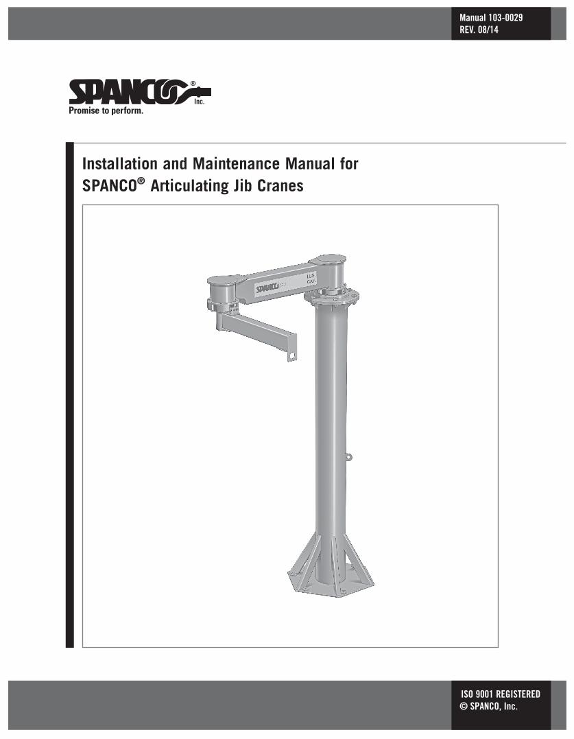
Installation and Maintenance Manual forSPANCO® Articulating Jib Cranes
Manual 103-0029REV. 08/14
ISO 9001 REGISTERED© SPANCO, Inc.

2
3
Forward...................................................................................................................... 4
Mast Installation (does not apply to ceiling or wall mounted)....................................... 4-6
Boom Installation....................................................................................................7-10
Acceptance Test........................................................................................................11
Maintenance.............................................................................................................12
Warranty and Service Policy........................................................................................13
TABLE OF CONTENTS

4
This manual contains important information to help you install, operate, maintain, andservice your new articulating jib crane. We recommend that you study its contentsthoroughly before putting the jib into use. We also recommend that you obtain the latestissue of ANSI B30.11 Safety Standard for Monorails and Underhung Cranes and study itscontents thoroughly. By practicing the recommended maintenance suggestions, with properinstallation, and the application of correct procedures you will be assured maximum servicefrom your jib crane.
The jibs described in this manual are intended for indoor service. Jib cranes used foroutdoor service require special consideration.
Information in this manual is subject to change without notice.
NOTE: If you have a ceiling or wall mounted articulating jib crane, skip this section.
Note: There are several types of base plate leveling methods to be used:
1. No shims or grout are required on a level and true smooth concrete surface.2. Use shims (by others) and grout, as required, to plumb the mast on an irregular concrete surface. (Be aware that the slightest deviation from level will be magnified by the height of the mast and will result in a possible “drift” of jib arm.3. Use leveling nuts (by others) and grout, as required.
For purposes of this manual, we will describe method three, leveling nuts and grout. Othermethods are similiar and may require special attention to anchor bolt projection lengths,grout thickness, and other onsite variables. In all cases, the finished installation requiresfull contact of the base plate on the foundation. All anchor bolts shall have plate washers(with standard holes) of adequate thickness for oversized base plate holes, per AISCrequirements. Along with plate washers, a standard washer shall be used on each anchorbolt.
IT IS SOLELY THE CUSTOMER’S RESPONSIBILITY TO PROVIDE THE PROPER FOUNDATION FOR THE JIB CRANE SO THERE SHOULD BE NO DEVIATION FROM THE RECOMMENDED FOUNDATION SIZE OR INSTALLATION RECOMMENDATIONS WITHOUT FIRST CONSULTING A QUALIFIED PROFESSIONAL.
This equipment is NOT, in any way, designed forlifting, supporting, or transporting humans.
FORWARD
MAST INSTALLATION(Refer to Figures 1 & 1A on Page 5)

5
1. After installing the recommended concrete (3,000 PSI) foundation, reinforcement, and anchor bolts (minimum 1 inch diameter), refer to the dimension sheet of your specific model jib crane (on www.spanco.com).
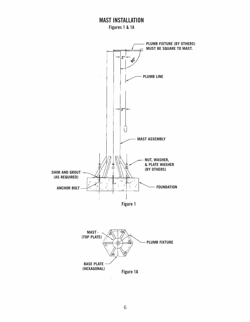
2. Install one set of leveling nuts on the anchor bolts with the top surface approximately one inch above the foundation. Next, place the mast assembly over the anchor bolts resting on leveling nuts. Install the second set of nuts, with plate washers and flat washers. Clamp the plumb fixture (a straight and rigid bar, level, or other custom made bracket) to mast top plate.
Note: Fixture must be perpendicular to the mast.
3. Select a position on the fixture arm, 2 inches from the edge of the mast, to hang a plumb line. Measure 60 inches down from the top of the mast and use this point to check the 2 inch dimension for mast plumb.
4. Position fixture arm directly over one anchor bolt and measure from the plumb line to the edge of the mast. If this measurement is not 2 inches, adjust the leveling nut directly below; turn leveling nut up if greater than 2 inches, down if less than 2 inches.
5. Rotate the fixture arm 180 degrees and re-check mast for plumb. Adjust leveling nuts until you have the same distance on each side of the mast. Repeat this operation at each anchor bolt or at 60 degree increments.
6. When mast is plumb tighten the locking nuts.
Note: Do not grout until installation of boom is complete.
MAST INSTALLATION continued...(Refer to Figures 1 & 1A on Page 5)
6
Figure 1
Figure 1A
MAST INSTALLATIONFigures 1 & 1A
MAST ASSEMBLY
NUT, WASHER, & PLATE WASHER (BY OTHERS)
FOUNDATIONANCHOR BOLT
SHIM AND GROUT(AS REQUIRED)
MAST(TOP PLATE)
PLUMB LINE
PLUMB FIXTURE
BASE PLATE(HEXAGONAL)
PLUMB FIXTURE (BY OTHERS)MUST BE SQUARE TO MAST.

7
Note: There is no adjustment in the boom, so the mast or any other support structure must be properlyinstalled (plumb) prior to boom installation.
INSTALLATION OF MAST MOUNTED JIB BOOM:
1. The boom comes from the factory fully assembled. If the bottom entry power option is used, it will need to be connected before the boom is set in its final position.
2. Carefully place boom into position and attach with (6) 1” diameter Grade 5 bolts or ASTM A325, flat washers, lock washers, and hex nuts. Tighten until lockwashers are fully flattened.* If rotation stops are to be installed, see instructions on page 10 before completely step 2.
BOOM INSTALLATION
MAST ASSEMBLY
BOOM ASSEMBLY
HEX BOLT
FLAT WASHER
LOCK WASHER
HEX NUTBoom with Mast
HEX JAM NUTSFRICTION BRAKE
8
Do not mount the jib crane to any structure unless you are sure thestructure can safely support the loads imposed upon the structure.Failure to check this item can result in severe bodily injury or death.
3. The installer is responsible for supplying the correct size, length, number, and type of bolts required to attach the jib crane brackets to the structure. SPANCO recommends that the bolts be ASTM A325 grade, or Grade 5.
4. Plan the installation such that the proper clearance as outlined in ANSI B30.11 will be adhered to. In the design of jib crane systems, all factors that influence clearances, such as roof truss sag and boom deflection shall be considered. To compensate for anticipated delfection, the boom tip should be adjusted to an elevation equal to Boom Length (inches) ÷ 300 above level.
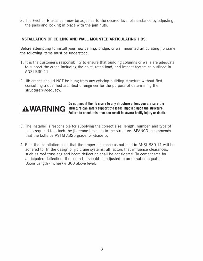
3. The Friction Brakes can now be adjusted to the desired level of resistance by adjusting the pads and locking in place with the jam nuts.
INSTALLATION OF CEILING AND WALL MOUNTED ARTICULATING JIBS:
Before attempting to install your new ceiling, bridge, or wall mounted articulating jib crane,the following items must be understood:
1. It is the customer’s responsibility to ensure that building columns or walls are adequate to support the crane including the hoist, rated load, and impact factors as outlined in ANSI B30.11.
2. Jib cranes should NOT be hung from any existing building structure without first consulting a qualified architect or engineer for the purpose of determining the structure’s adequacy.
9
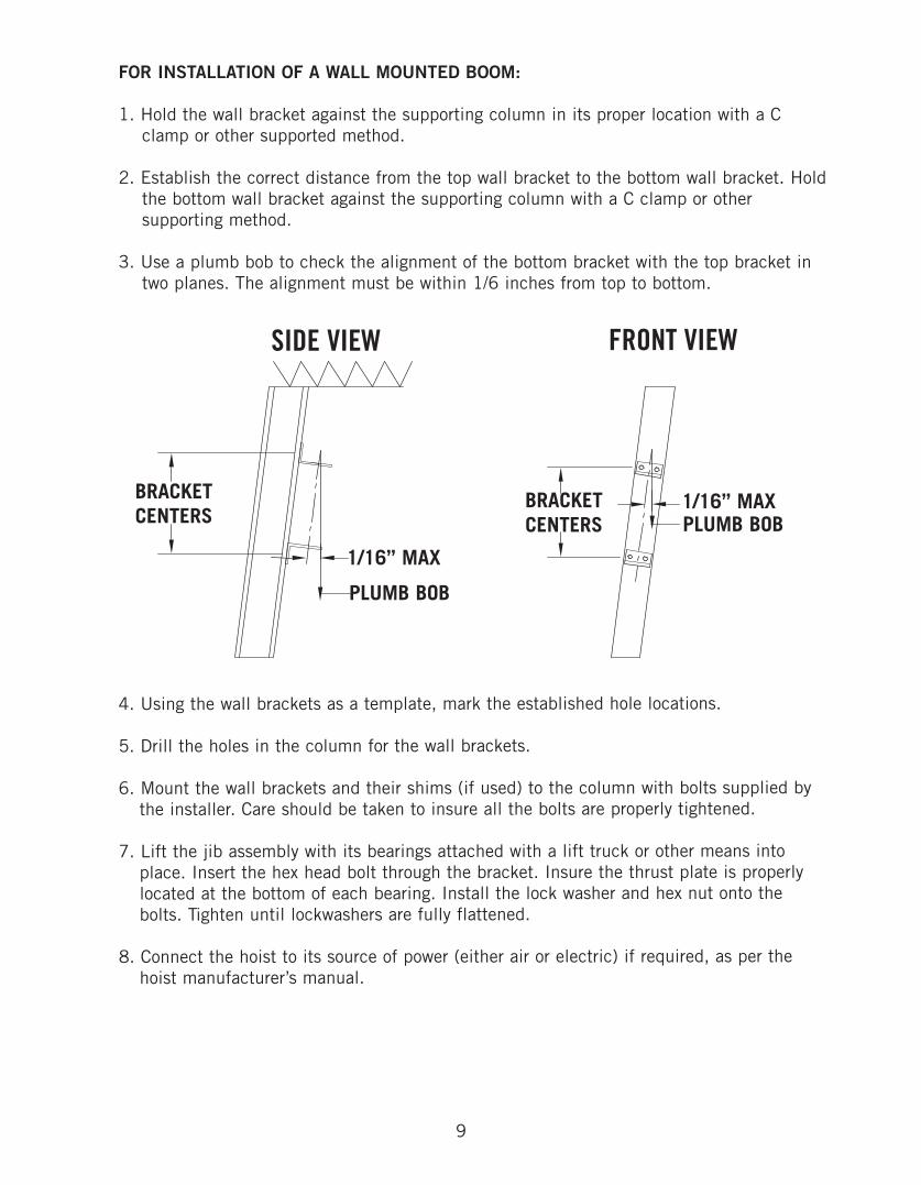
FOR INSTALLATION OF A WALL MOUNTED BOOM:
1. Hold the wall bracket against the supporting column in its proper location with a C clamp or other supported method.
2. Establish the correct distance from the top wall bracket to the bottom wall bracket. Holdthe bottom wall bracket against the supporting column with a C clamp or other supporting method.
3. Use a plumb bob to check the alignment of the bottom bracket with the top bracket in two planes. The alignment must be within 1/6 inches from top to bottom.
4. Using the wall brackets as a template, mark the established hole locations.
5. Drill the holes in the column for the wall brackets.
6. Mount the wall brackets and their shims (if used) to the column with bolts supplied by the installer. Care should be taken to insure all the bolts are properly tightened.
7. Lift the jib assembly with its bearings attached with a lift truck or other means into place. Insert the hex head bolt through the bracket. Insure the thrust plate is properly located at the bottom of each bearing. Install the lock washer and hex nut onto the bolts. Tighten until lockwashers are fully flattened.
8. Connect the hoist to its source of power (either air or electric) if required, as per the hoist manufacturer’s manual.
SIDE VIEW FRONT VIEW
PLUMB BOB
PLUMB BOB1/16” MAX
1/16” MAX
BRACKETCENTERS
BRACKETCENTERS
10
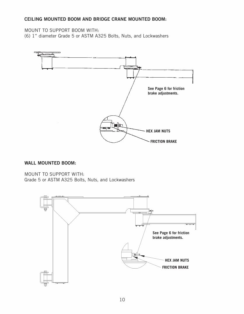
WALL MOUNTED BOOM:
MOUNT TO SUPPORT WITH:Grade 5 or ASTM A325 Bolts, Nuts, and Lockwashers
CEILING MOUNTED BOOM AND BRIDGE CRANE MOUNTED BOOM:
MOUNT TO SUPPORT BOOM WITH:(6) 1” diameter Grade 5 or ASTM A325 Bolts, Nuts, and Lockwashers
HEX JAM NUTS
FRICTION BRAKE
See Page 6 for frictionbrake adjustments.
HEX JAM NUTS
FRICTION BRAKE
See Page 6 for frictionbrake adjustments.
11
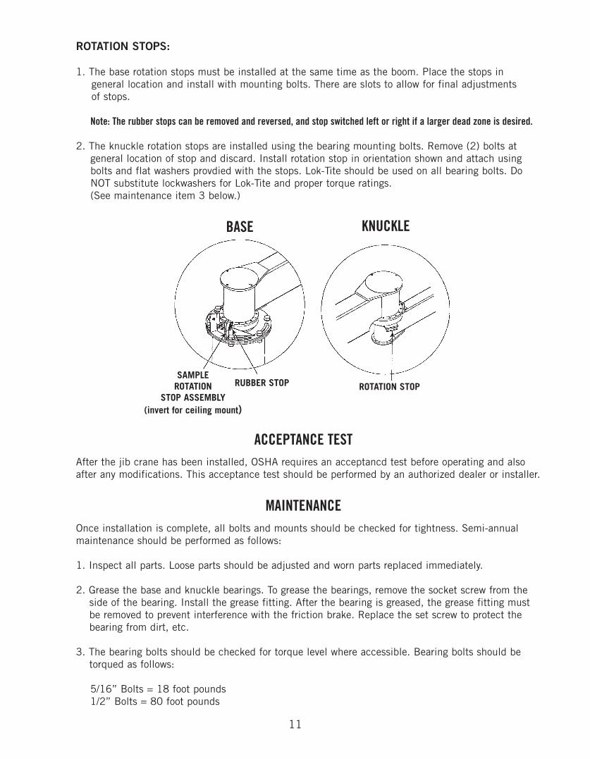
ROTATION STOPS:
1. The base rotation stops must be installed at the same time as the boom. Place the stops in general location and install with mounting bolts. There are slots to allow for final adjustments of stops.
Note: The rubber stops can be removed and reversed, and stop switched left or right if a larger dead zone is desired.
2. The knuckle rotation stops are installed using the bearing mounting bolts. Remove (2) bolts at general location of stop and discard. Install rotation stop in orientation shown and attach using bolts and flat washers provdied with the stops. Lok-Tite should be used on all bearing bolts. Do NOT substitute lockwashers for Lok-Tite and proper torque ratings. (See maintenance item 3 below.)
BASE KNUCKLE
SAMPLEROTATION
STOP ASSEMBLY(invert for ceiling mount)
RUBBER STOP ROTATION STOP
Once installation is complete, all bolts and mounts should be checked for tightness. Semi-annualmaintenance should be performed as follows:
1. Inspect all parts. Loose parts should be adjusted and worn parts replaced immediately.
2. Grease the base and knuckle bearings. To grease the bearings, remove the socket screw from theside of the bearing. Install the grease fitting. After the bearing is greased, the grease fitting mustbe removed to prevent interference with the friction brake. Replace the set screw to protect the bearing from dirt, etc.
3. The bearing bolts should be checked for torque level where accessible. Bearing bolts should be torqued as follows:
5/16” Bolts = 18 foot pounds1/2” Bolts = 80 foot pounds
ACCEPTANCE TEST
MAINTENANCE
After the jib crane has been installed, OSHA requires an acceptancd test before operating and alsoafter any modifications. This acceptance test should be performed by an authorized dealer or installer.

12
SPANCO, Inc.604 Hemlock RoadMorgantown, PA, 19543
Toll Free: (800) 869-2080Local: (610) 286-7200Fax: (610) 286-0085
Spanco.com
TEN-YEAR SPANCO WARRANTY
Products covered under the Ten-Year Warranty:
• Manual Steel Freestanding, Ceiling Mounted Workstation Bridge Cranes, and Monorails• Manual Aluminum (Alu-Track®) Workstation Bridge Cranes and Monorails• Manual Jib Cranes (I-Beam, Articulating, and Workstation Jib Cranes)• Manual Gantry Cranes and Tripods
What the Ten-Year Warranty covers:
• Defects in Equipment material and workmanship• Wearable parts (end truck and hoist trolley wheels only)
Spanco, Inc. warrants its manual workstation bridge crane products, jib crane products, and gantry crane productsto be free from defects in material and workmanship for a period of ten (10) years or 20,000 hours, commencingon the date of shipment to the first retail purchaser. This warranty extends to non-wearable parts only, with the exception of the wheels supplied on manually operated workstation end trucks and hoist trolleys. This warrantydoes not cover defective equipment or system failure caused by misuse, negligence, improper installation or maintenance, or equipment that has been used in excess of its rated capacity or beyond its service factors. Itdoes not apply to equipment that has been altered without Spanco’s written authorization.
Written notice of any claimed system defect must be given to Spanco within thirty days of discovery. Spanco's obligation under this warranty is limited to the replacement or repair of Spanco’s products at the factory or separate location approved by Spanco. The purchaser is responsible for all freight and transportation costs relatingto equipment repair or replacement. Other than the abovementioned warranty, Spanco will not honor any other warranties—whether express, implied, or statutory—and disclaims any warranties of merchantability or fitness for a particular purpose. Spanco is not liable—under any circumstances—for any indirect, incidental, or consequential damages including but not limited to lost profits, increased operating costs, or loss of production.
This warranty does not extend to components or accessories not manufactured by Spanco. The purchaser’s remedyfor such components and accessories will be determined by the terms and conditions of any the warranty providedby the manufacturer of such components and accessories.
NOTE: All motorized Spanco products come with a One-Year Warranty on drive components.