Embed Size (px)
Citation preview
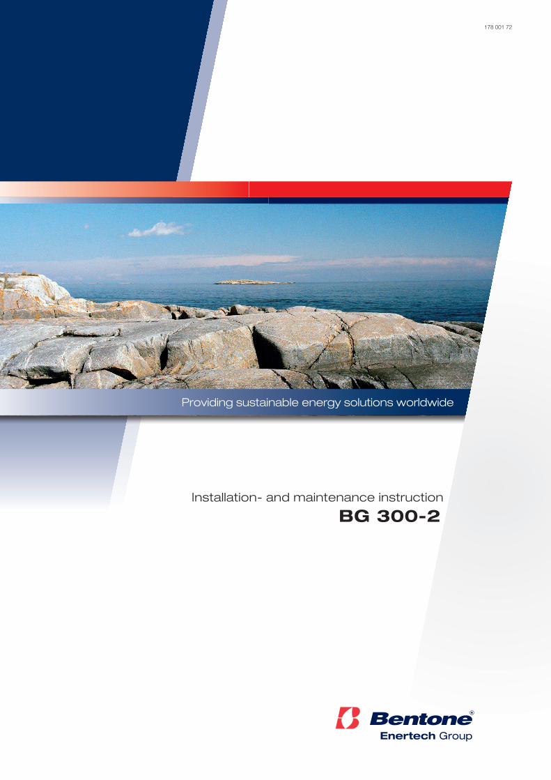
Providing sustainable energy solutions worldwide
178 001 72
Installation- and maintenance instruction
BG 300-2

172 205 32 08-01
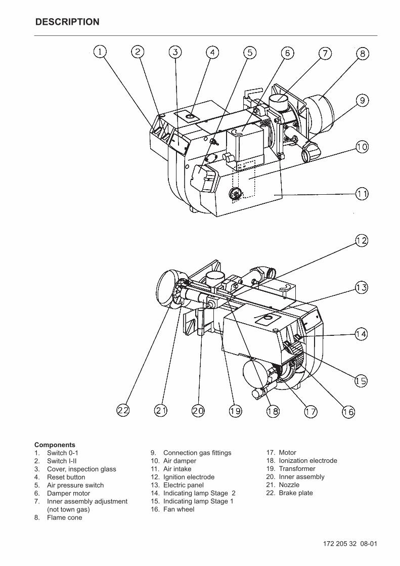
DESCRIPTION
Components1. Switch 0-12. Switch I-II3. Cover, inspection glass4. Reset button5. Air pressure switch6. Damper motor7. Inner assembly adjustment
(not town gas)8. Flame cone
9. Connection gas fittings10. Air damper11. Air intake12. Ignition electrode13. Electric panel14. Indicating lamp Stage 215. Indicating lamp Stage 116. Fan wheel
17. Motor18. Ionization electrode19. Transformer20. Inner assembly21. Nozzle22. Brake plate
Capacity chart according to EN 676
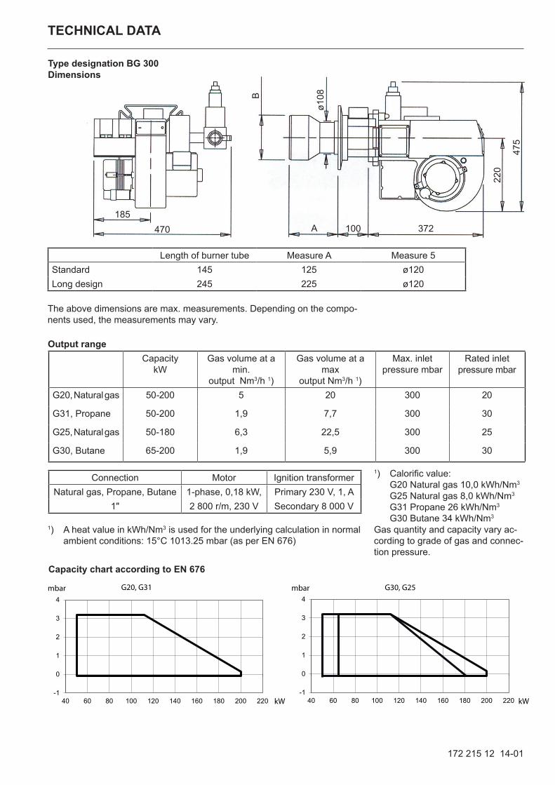
Output range
TECHNICAL DATA
The above dimensions are max. measurements. Depending on the compo-nents used, the measurements may vary.
172 215 12 14-01
Length of burner tube Measure A Measure 5Standard 145 125 ø120Long design 245 225 ø120
100 372
220
475
B
A
ø108
185470
Type designation BG 300Dimensions
Capacity kW
Gas volume at a min.
output Nm3/h 1)
Gas volume at a max
output Nm3/h 1)
Max. inlet pressure mbar
Rated inlet pressure mbar
G20, Natural gas 50-200 5 20 300 20
G31, Propane 50-200 1,9 7,7 300 30
G25, Natural gas 50-180 6,3 22,5 300 25
G30, Butane 65-200 1,9 5,9 300 30
Connection Motor Ignition transformerNatural gas, Propane, Butane 1-phase, 0,18 kW, Primary 230 V, 1, A
1" 2 800 r/m, 230 V Secondary 8 000 V
-1
0
1
2
3
4
40 60 80 100 120 140 160 180 200 220
mbar
kW
G20, G31
-1
0
1
2
3
4
40 60 80 100 120 140 160 180 200 220
mbar
kW
G30, G25
1) Calorific value: G20 Natural gas 10,0 kWh/Nm3
G25 Natural gas 8,0 kWh/Nm3 G31 Propane 26 kWh/Nm3 G30 Butane 34 kWh/Nm3
Gas quantity and capacity vary ac-cording to grade of gas and connec-tion pressure.
1) A heat value in kWh/Nm3 is used for the underlying calculation in normal ambient conditions: 15°C 1013.25 mbar (as per EN 676)
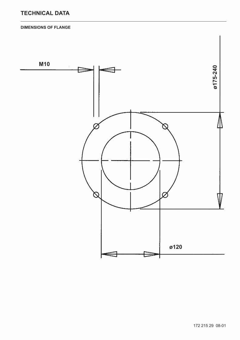
TECHNICAL DATA
172 215 29 08-01
DIMENSIONS OF FLANGE
ø175
-240
M10
ø120
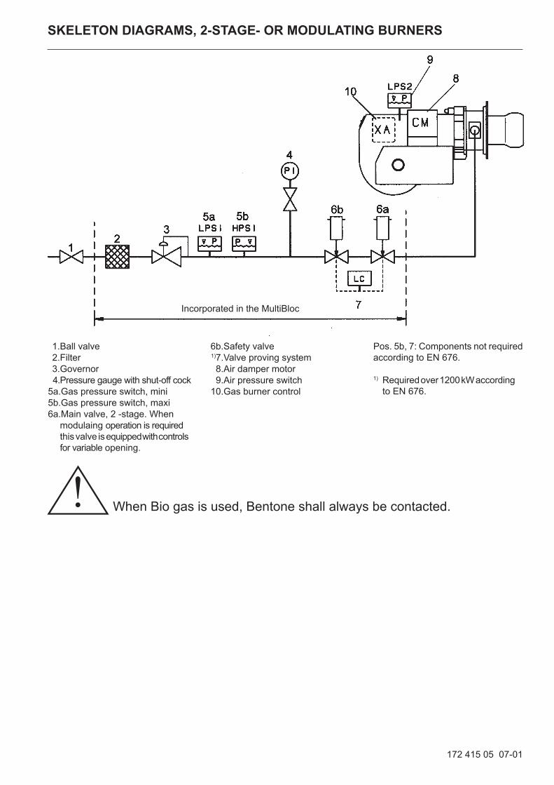
SKELETON DIAGRAMS, 2-STAGE- OR MODULATING BURNERS
1. Ball valve 2. Filter 3. Governor 4. Pressure gauge with shut-off cock 5a. Gas pressure switch, mini 5b. Gas pressure switch, maxi 6a. Main valve, 2 -stage. When modulaing operation is required this valve is equipped with controls for variable opening.
Incorporated in the MultiBloc
6b. Safety valve 1)7. Valve proving system 8. Air damper motor 9. Air pressure switch 10. Gas burner control
Pos. 5b, 7: Components not required according to EN 676.
1) Required over 1200 kW according to EN 676.
172 415 05 07-01
When Bio gas is used, Bentone shall always be contacted.!
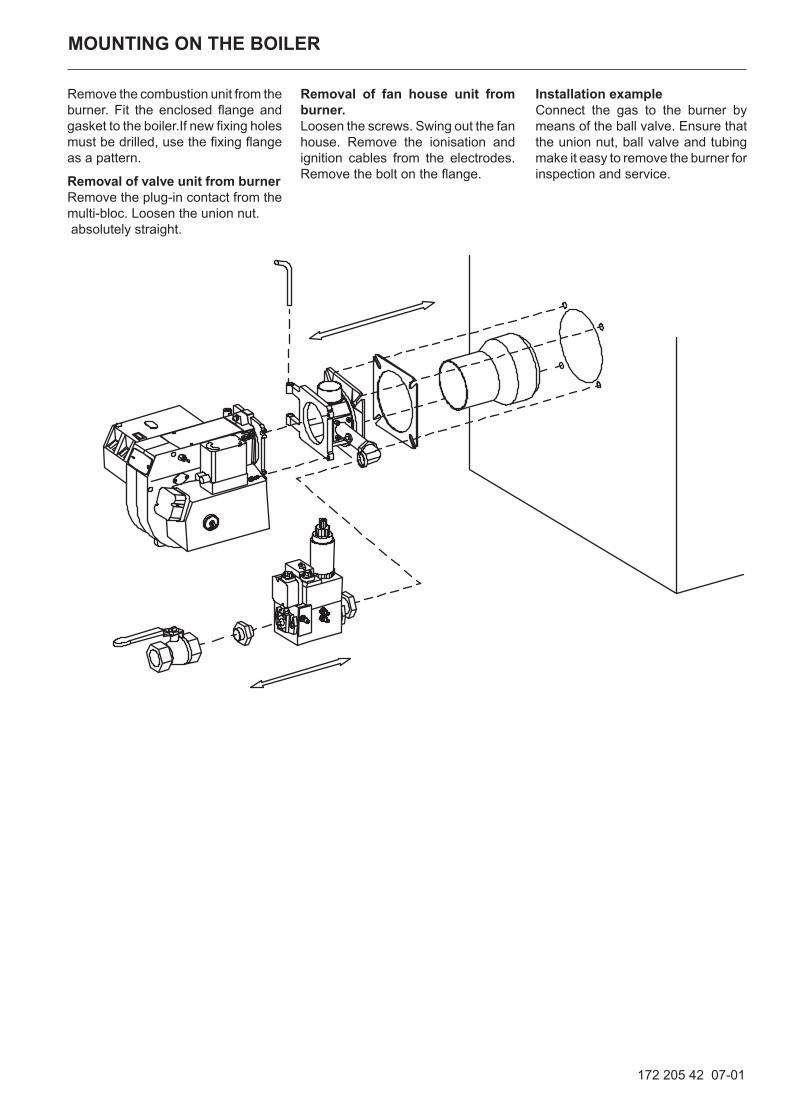
Removal of fan house unit from burner.Loosen the screws. Swing out the fan house. Remove the ionisation and ignition cables from the electrodes. Remove the bolt on the flange.
Remove the combustion unit from the burner. Fit the enclosed flange and gasket to the boiler.If new fixing holes must be drilled, use the fixing flange as a pattern.
Removal of valve unit from burnerRemove the plug-in contact from the multi-bloc. Loosen the union nut. absolutely straight.
MOUNTING ON THE BOILER
Installation exampleConnect the gas to the burner by means of the ball valve. Ensure that the union nut, ball valve and tubing make it easy to remove the burner for inspection and service.
172 205 42 07-01
172 425 28 08-01
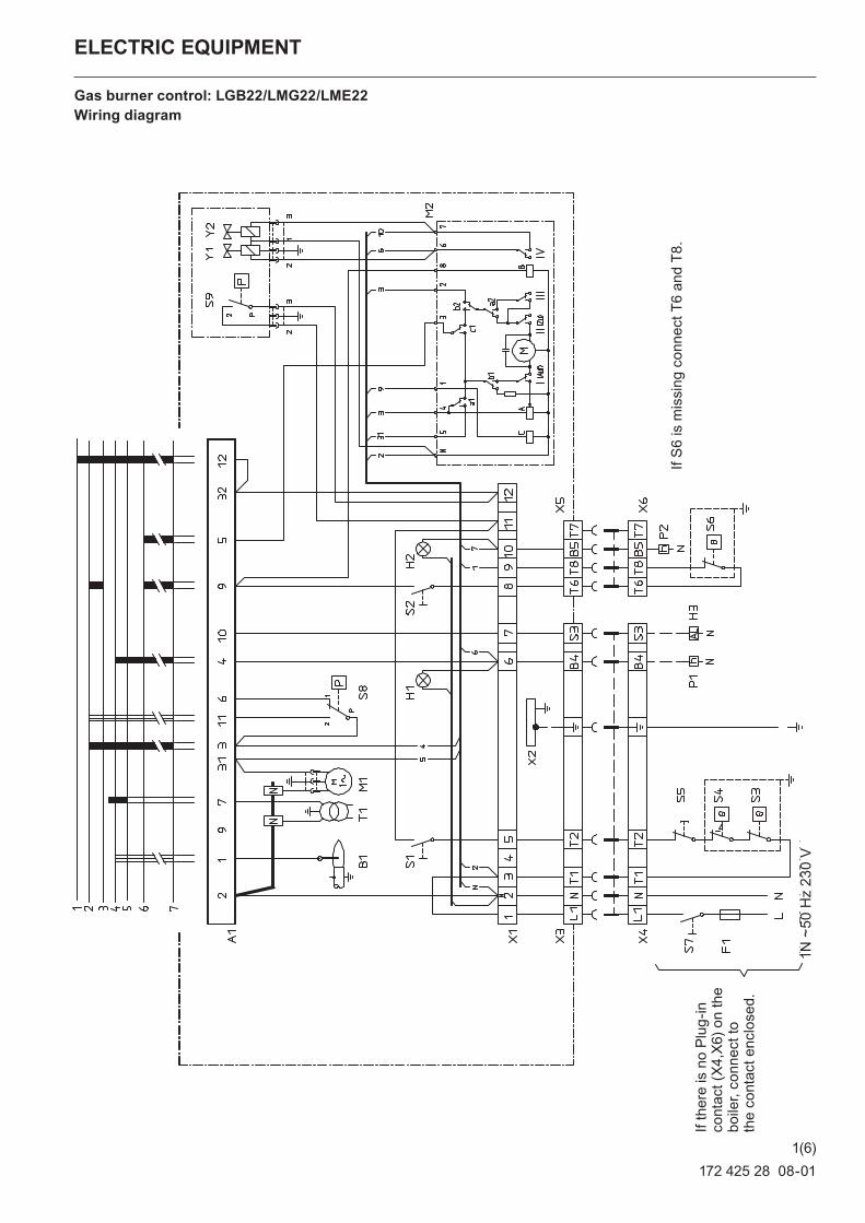
ELECTRIC EQUIPMENT
Gas burner control: LGB22/LMG22/LME22Wiring diagram
If th
ere
is n
o Pl
ug-in
co
ntac
t (X4
,X6)
on
the
boile
r, co
nnec
t to
the
cont
act e
nclo
sed.
If S
6 is
mis
sing
con
nect
T6
and
T8.
1(6)
1N ~
50 H
z 23
0 V
172 425 28 08-01
ELECTRIC EQUIPMENT
Gas burner control: LGB22/LMG22/LME22
Function1. Operating switch ON-Thermostat ON-Gas pressure switch ON-Air damper closed.
A control is made that the air pressure switch does not indicate fan pressure. Then the burner motor starts.
2. Air damper motor opens. The air damper motor opens the damper to full load. A control is made that the air pres-sure switch indicates sufficient fan pressure.
3. Air damper motor closes. The air damper motor closes to low load . Then the ignition spark is formed.
4. Main and safety valves open The gas is ignited. The ionization electrode indicates a flame.
5. The safety time expires. The ignition spark goes out. The safety time expires. If there is no flame or if for some reason the flame disappears after this time limit, the burner control locks out.
6. Operating position. The burner is in operating position and can now change over to full load if the operat-ing switch and the thermostat for full load are in positon ON. The burner can alternate between full and low load depending on set temperature.
7. Stop. The operation of the burner can now be interrupted by means of the operating switch or the thermostat.
• The control locks out. The red lamp in the control is lit. Restart the burner by pressing the reset button.
2(6)
List of componentsA1 Gas burner control B1 Ionization electrodeF1 Operating fuseH1 Lamp, low capacityH2 Lamp, high capacityH3 Alarm signal 230 VM1 Burner motorM2 Damper motor, L&S SQN75.254.A21BP1 Time meter, total operating timeP2 Time meter, high capacity, total operating timeS1 Operating switchS2 Operating switch, stage 2S3 Control thermostatS4 Temperature limiter
S5 Micro switch for hinged doorS6 Control thermostat, stage 2S7 Main switchS8 Air pressure switchS9 Gas pressure switchT1 Ignition transformerX1 Connection terminal boardX2 Earth terminal X3 Plug-in contact, burnerX4 Plug-in contact, boilerX5 Plug-in contact, stage 2, burnerX6 Plug-in contact, stage 2, boilerY1 Gas solenoid valve 1Y2 Gas solenoid valve 2
Mains connection in accordance with local regulations.
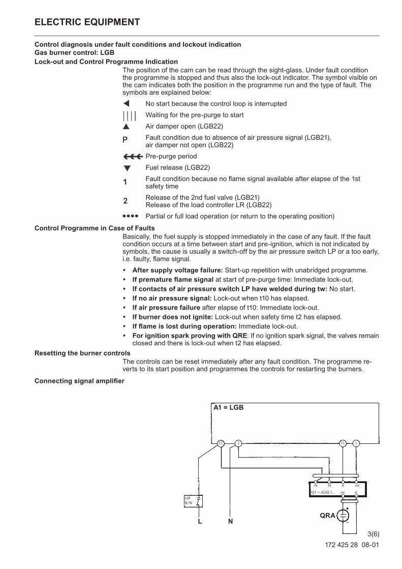
A1 = LGB
GP R/W
L N
br bl rt sw
sw rtQ1 = AGQ 1...
QRA
11112 2
172 425 28 08-01
ELECTRIC EQUIPMENT
Control diagnosis under fault conditions and lockout indication Gas burner control: LGBLock-out and Control Programme Indication
The position of the cam can be read through the sight-glass. Under fault condition the programme is stopped and thus also the lock-out indicator. The symbol visible on the cam indicates both the position in the programme run and the type of fault. The symbols are explained below:
No start because the control loop is interrupted
Waiting for the pre-purge to start
Air damper open (LGB22)
Fault condition due to absence of air pressure signal (LGB21), air damper not open (LGB22)
Pre-purge period
Fuel release (LGB22)
Fault condition because no flame signal available after elapse of the 1st safety time
Release of the 2nd fuel valve (LGB21) Release of the load controller LR (LGB22)
Partial or full load operation (or return to the operating position)
Control Programme in Case of FaultsBasically, the fuel supply is stopped immediately in the case of any fault. If the fault condition occurs at a time between start and pre-ignition, which is not indicated by symbols, the cause is usually a switch-off by the air pressure switch LP or a too early, i.e. faulty, flame signal.
• After supply voltage failure: Start-up repetition with unabridged programme.• If premature flame signal at start of pre-purge time: Immediate lock-out.• If contacts of air pressure switch LP have welded during tw: No start.• If no air pressure signal: Lock-out when t10 has elapsed.• If air pressure failure after elapse of t10: Immediate lock-out.• If burner does not ignite: Lock-out when safety time t2 has elapsed.• If flame is lost during operation: Immediate lock-out.• For ignition spark proving with QRE: If no ignition spark signal, the valves remain
closed and there is lock-out when t2 has elapsed.Resetting the burner controls
The controls can be reset immediately after any fault condition. The programme re-verts to its start position and programmes the controls for restarting the burners.
Connecting signal amplifier
3(6)
A1 = LMG
GP R/W
L N
br bl rt sw
sw rtQ1 = AGQ 2...
QRA
11112 2
172 425 28 08-01
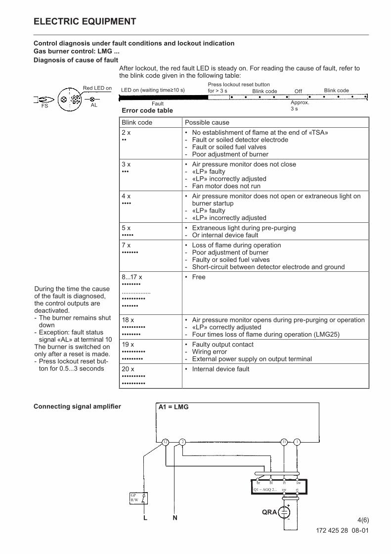
During the time the cause of the fault is diagnosed, the control outputs are deactivated. - The burner remains shut down
- Exception: fault status signal «AL» at terminal 10
The burner is switched on only after a reset is made. - Press lockout reset but-ton for 0.5...3 seconds
ELECTRIC EQUIPMENT
Control diagnosis under fault conditions and lockout indication Gas burner control: LMG ...Diagnosis of cause of fault
After lockout, the red fault LED is steady on. For reading the cause of fault, refer to the blink code given in the following table:
Connecting signal amplifier
Error code table
Blink code Possible cause2 x••
• No establishment of flame at the end of «TSA» - Fault or soiled detector electrode - Fault or soiled fuel valves - Poor adjustment of burner
3 x•••
• Air pressure monitor does not close - «LP» faulty - «LP» incorrectly adjusted - Fan motor does not run
4 x••••
• Air pressure monitor does not open or extraneous light on burner startup
- «LP» faulty - «LP» incorrectly adjusted
5 x•••••
• Extraneous light during pre-purging - Or internal device fault
7 x•••••••
• Loss of flame during operation - Poor adjustment of burner - Faulty or soiled fuel valves - Short-circuit between detector electrode and ground
8...17 x••••••••.................•••••••••••••••••
• Free
18 x••••••••••••••••••
• Air pressure monitor opens during pre-purging or operation - «LP» correctly adjusted - Four times loss of flame during operation (LMG25)
19 x•••••••••••••••••••
• Faulty output contact - Wiring error - External power supply on output terminal
20 x••••••••••••••••••••
• Internal device fault
ALFS
Red LED on LED on (waiting time≥10 s)
Fault
Press lockout reset button for > 3 s Blink code Off Blink code
Approx. 3 s
4(6)
172 425 28 08-01
ELECTRIC EQUIPMENT
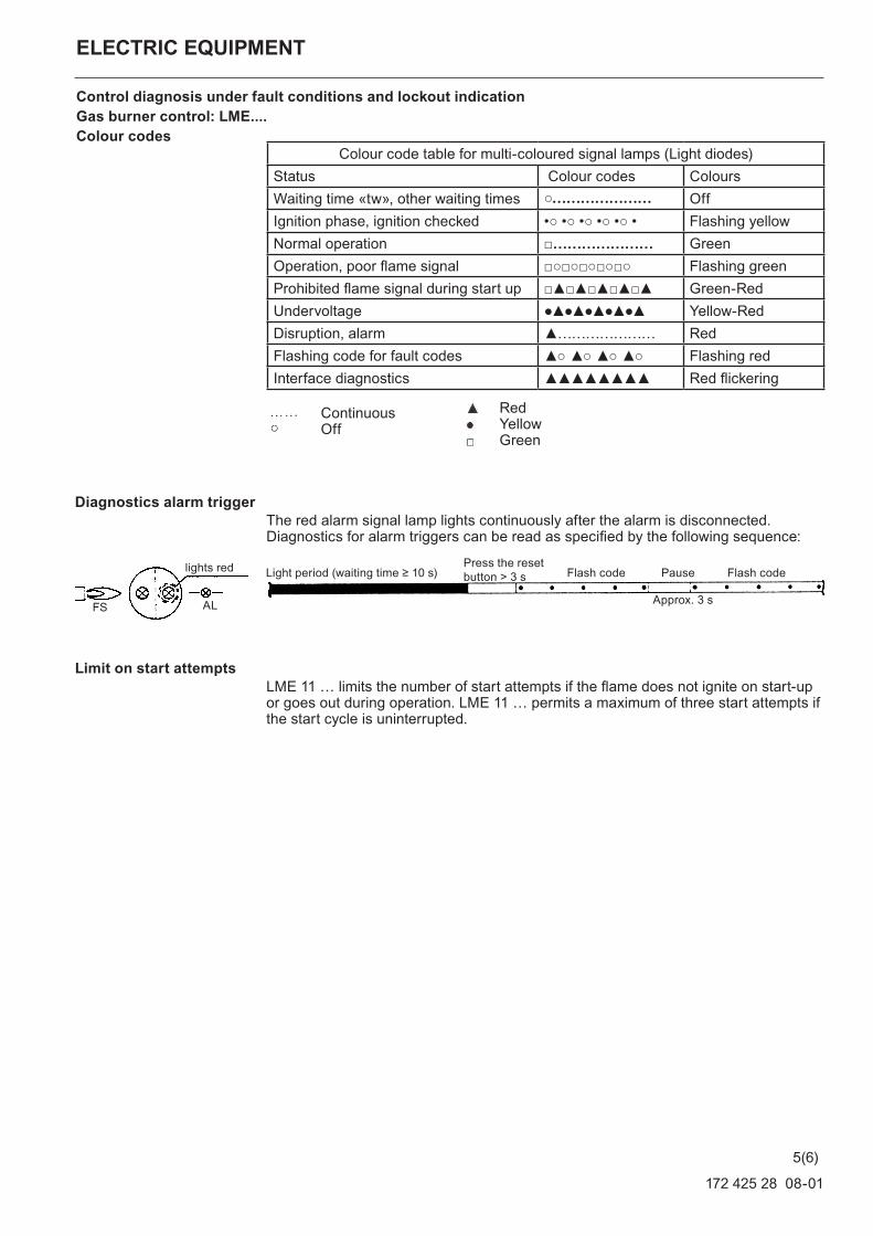
Control diagnosis under fault conditions and lockout indication Gas burner control: LME....Colour codes
Diagnostics alarm triggerThe red alarm signal lamp lights continuously after the alarm is disconnected. Diagnostics for alarm triggers can be read as specified by the following sequence:
Limit on start attempts
LME 11 … limits the number of start attempts if the flame does not ignite on start-up or goes out during operation. LME 11 … permits a maximum of three start attempts if the start cycle is uninterrupted.
ContinuousOff
RedYellowGreen
Colour code table for multi-coloured signal lamps (Light diodes)Status Colour codes ColoursWaiting time «tw», other waiting times ○………………… OffIgnition phase, ignition checked •○ •○ •○ •○ •○ • Flashing yellowNormal operation □………………… GreenOperation, poor flame signal □○□○□○□○□○ Flashing greenProhibited flame signal during start up □▲□▲□▲□▲□▲ Green-RedUndervoltage ●▲●▲●▲●▲●▲ Yellow-RedDisruption, alarm ▲………………… RedFlashing code for fault codes ▲○ ▲○ ▲○ ▲○ Flashing redInterface diagnostics ▲▲▲▲▲▲▲▲ Red flickering
Light period (waiting time ≥ 10 s)
ALFS
Flash code Pause Flash code
Approx. 3 s
lights red Press the reset button > 3 s
5(6)
172 425 28 08-01
ELECTRIC EQUIPMENT
Control diagnosis under fault conditions and lockout indication Gas burner control: LME...
During alarm trigger diagnostics, control outputs are to be disconnected from all power.
- The burner is disconnected - Exception, the «AL» alarm signal at connection block 10
The burner is only to be reconnected after it is reset - Press the reset button 0.5...3 s
Interface diagnosticsTo switch to interface mode, hold the reset button depressed for more than 3 s. To return to normal mode, hold the reset button depressed for more than 3 s. If the firing unit is in the alarm mode, it is reset by pressing the reset button 0.5...3 s.
Connecting signal amplifier
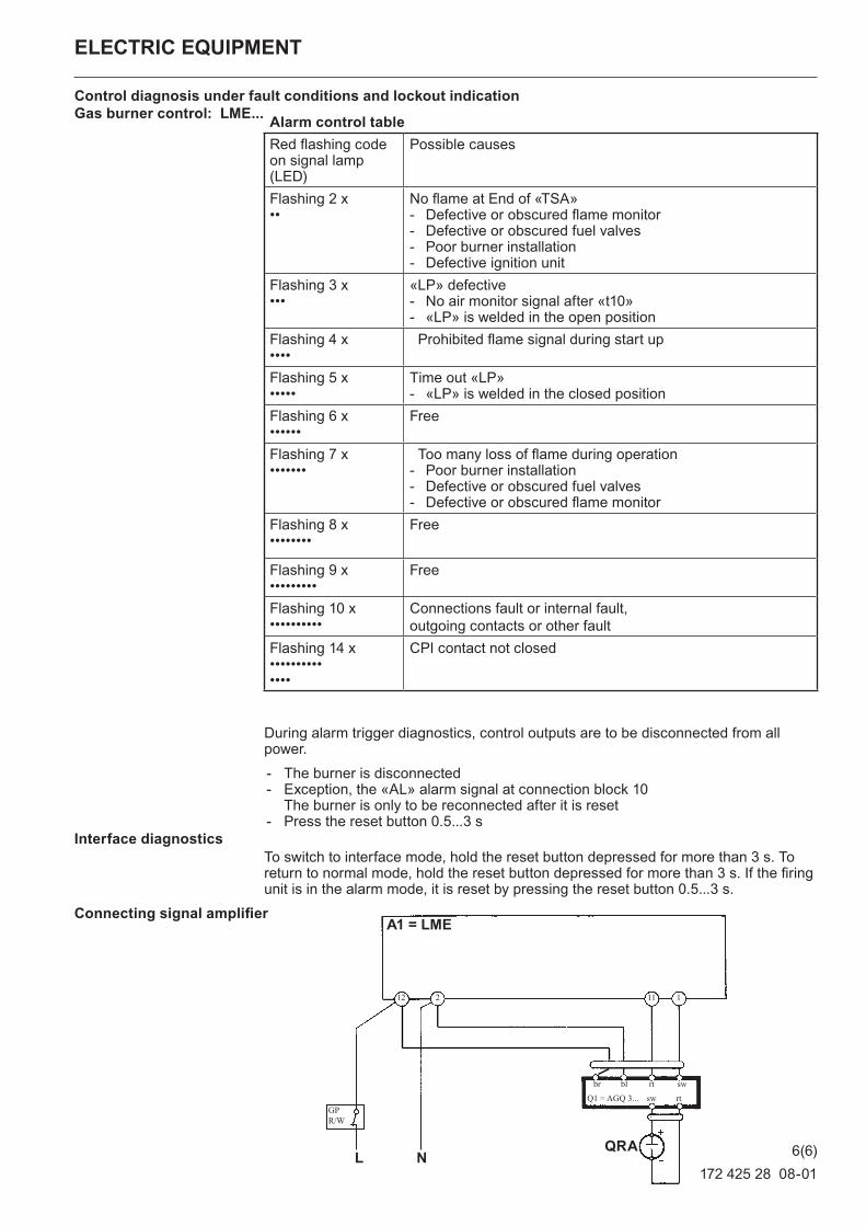
Alarm control tableRed flashing code on signal lamp (LED)
Possible causes
Flashing 2 x••
No flame at End of «TSA» - Defective or obscured flame monitor - Defective or obscured fuel valves - Poor burner installation - Defective ignition unit
Flashing 3 x•••
«LP» defective - No air monitor signal after «t10» - «LP» is welded in the open position
Flashing 4 x••••
Prohibited flame signal during start up
Flashing 5 x•••••
Time out «LP» - «LP» is welded in the closed position
Flashing 6 x••••••
Free
Flashing 7 x•••••••
Too many loss of flame during operation - Poor burner installation - Defective or obscured fuel valves - Defective or obscured flame monitor
Flashing 8 x••••••••
Free
Flashing 9 x•••••••••
Free
Flashing 10 x••••••••••
Connections fault or internal fault,outgoing contacts or other fault
Flashing 14 x••••••••••••••
CPI contact not closed
A1 = LME
GP R/W
L N
br bl rt swsw rtQ1 = AGQ 3...
QRA
11112 2
6(6)
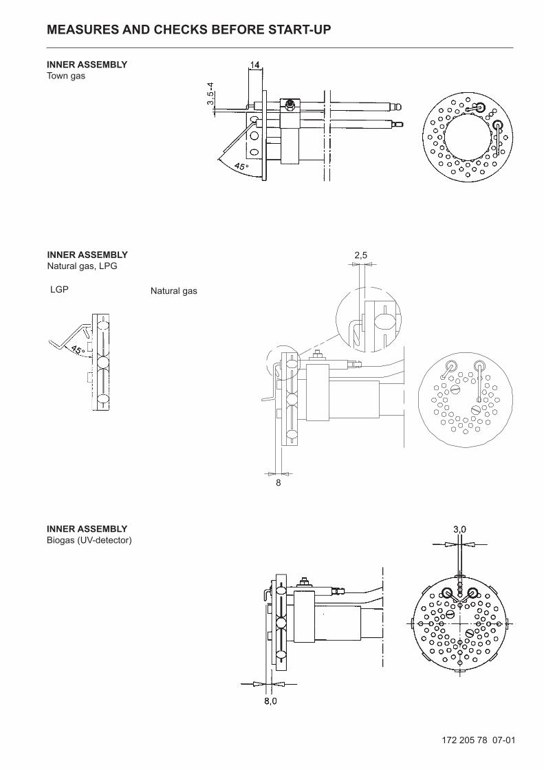
MEASURES AND CHECKS BEFORE START-UP,
General rulesCare should be taken by the installer to ensure that no electrical cables or fuel/gas pipes are trapped or damaged during installation or service/mainte-nance.
Inner assemblyEnsure that the ignition and ionisation electrodes are correctly adjusted. The sketch shows the correct measure-ments.
Gas quality Ensure that the burner head is meant for the gas quality to be used (see fig.)
VentingThe gas line is vented by loosening the screw on the test nipple for the inlet pressure. Connect a plastic hose and conduct the gas into the open. After having vented the gas line tighten the screw again.
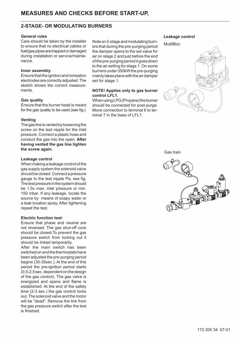
Leakage controlWhen making a leakage control of the gas supply system the solenoid valve should be closed. Connect a pressure gauge to the test nipple Pa, see fig. The test pressure in the system should be 1,5x max. inlet pressure or min. 150 mbar. If any leakage, locate the source by means of soapy water or a leak location spray. After tightening repeat the test.
Electric function test:Ensure that phase and neutral are not reversed. The gas shut-off cock should be closed.To prevent the gas pressure switch from locking out it should be linked temporarily.After the main switch has been switched on and the thermostats have been adjusted the pre-purging period begins (30-35sec.). At the end of this period the pre-ignition period starts (0,5-2,5 sec. dependent on the design of the gas control). The gas valve is energized and opens and flame is established. At the end of the safety time (2-3 sec.) the gas control locks out. The solenoid valve and the motor will be "dead". Remove the link from the gas pressure switch after the test is finished.
172 205 34 07-01
Leakage control
Gas train
Note on 2-stage and modulating burn-ers that during the pre-purging period the damper opens to the set value for air on stage 2 and just before the end of the pre-purging period it goes down to the air setting for stage 1. On some burners under 350kW the pre-purging mainly takes place with the air damper set for stage 1.
NOTE! Applies only to gas burner control LFL1.When using LPG (Propane) the burner should be connected for post-purge. Move connection to terminal 6 to ter-minal 7 in the base of LFL1.
2-STAGE- OR MODULATING BURNERS
MultiBloc
MEASURES AND CHECKS BEFORE START-UP
172 205 78 07-01
INNER ASSEMBLYTown gas
INNER ASSEMBLYNatural gas, LPG
INNER ASSEMBLYBiogas (UV-detector)
Natural gasLGP
2,5
8
172 205 16 07-01
If the barometer height, pressure and temperature of the gas deviate very much from the normal values this must be taken into account as follows:
f = 273+t . 1013,25273 B+Pu
t = Temperature of the gas at the gas meter (15°C)
B = Barometer height (945 mbar)
Pu = Pressure of the gas at the gas meter (15,0 mbar)
f = 273+15 . 1013,25273 945+15
f = 11,1
The gas volume read on the gas meter actually reads 1,11 . 12,9 = 14,4 m3/h.
Net calorific valueGas quality kWh/Nm3 kJ/Nm3 kcal/Nm3
Natural gas 10,3 37 144 8 865Propane 26,0 93 647 22 350Butane 34,3 123 571 29 492Town gas 4,9 17 653 4 213Bio gas 7,0 25 219 6 019
V = Gas volume Nm3/h
Q = Boiler output 120 kW
Hu = Calorific value of the gas A. 37 144 kJ/Nm3, B. 10.3 kWh/Nm3
η = Expected efficiency 90%
Ex. A v=Q .3 600
=120 . 3 600
≈ 12,9 Nm3/hHu
· η 37 144 . 0,90
Ex. B v=120
≈ 12,9 Nm3/h10,3 · 0,90
Example how to calculate the gas volume (natural gas)
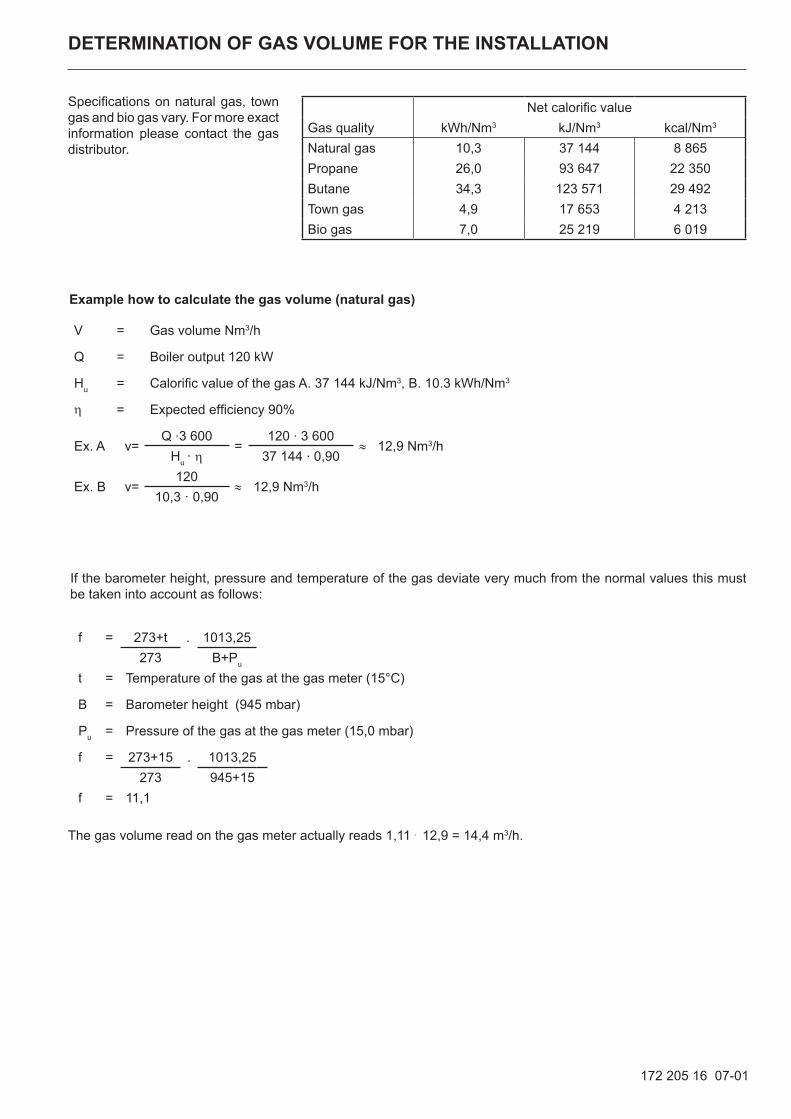
DETERMINATION OF GAS VOLUME FOR THE INSTALLATION
Specifications on natural gas, town gas and bio gas vary. For more exact information please contact the gas distributor.
172 305 70 08-01
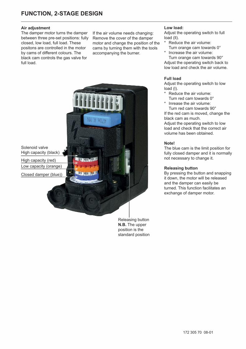
Air adjustmentThe damper motor turns the damper between three pre-set positions: fully closed, low load, full load. These positons are controlled in the motor by cams of different colours. The black cam controls the gas valve for full load.
Low load:Adjust the operating switch to full load (ll).* Reduce the air volume:
Turn orange cam towards 0°* Increase the air volume:
Turn orange cam towards 90°Adjust the operating switch back to low load and check the air volume.
Full loadAdjust the operating switch to low load (l).* Reduce the air volume:
Turn red cam towards 0°* Inrease the air volume:
Turn red cam towards 90°If the red cam is moved, change the black cam as much.Adjust the operating switch to low load and check that the correct air volume has been obtained.
Note! The blue cam is the limit position for fully closed damper and it is normally not necessary to change it.
Releasing buttonBy pressing the button and snapping it down, the motor will be released and the damper can easily be turned. This function facilitates an exchange of damper motor.
If the air volume needs changing: Remove the cover of the damper motor and change the position of the cams by turning them with the tools accompanying the burner.
FUNCTION, 2-STAGE DESIGN
Solenoid valveHigh capacity (black)
High capacity (red)Low capacity (orange)
Closed damper (blue))
Releasing button N.B. The upper position is the standard position
172 505 03 08-01
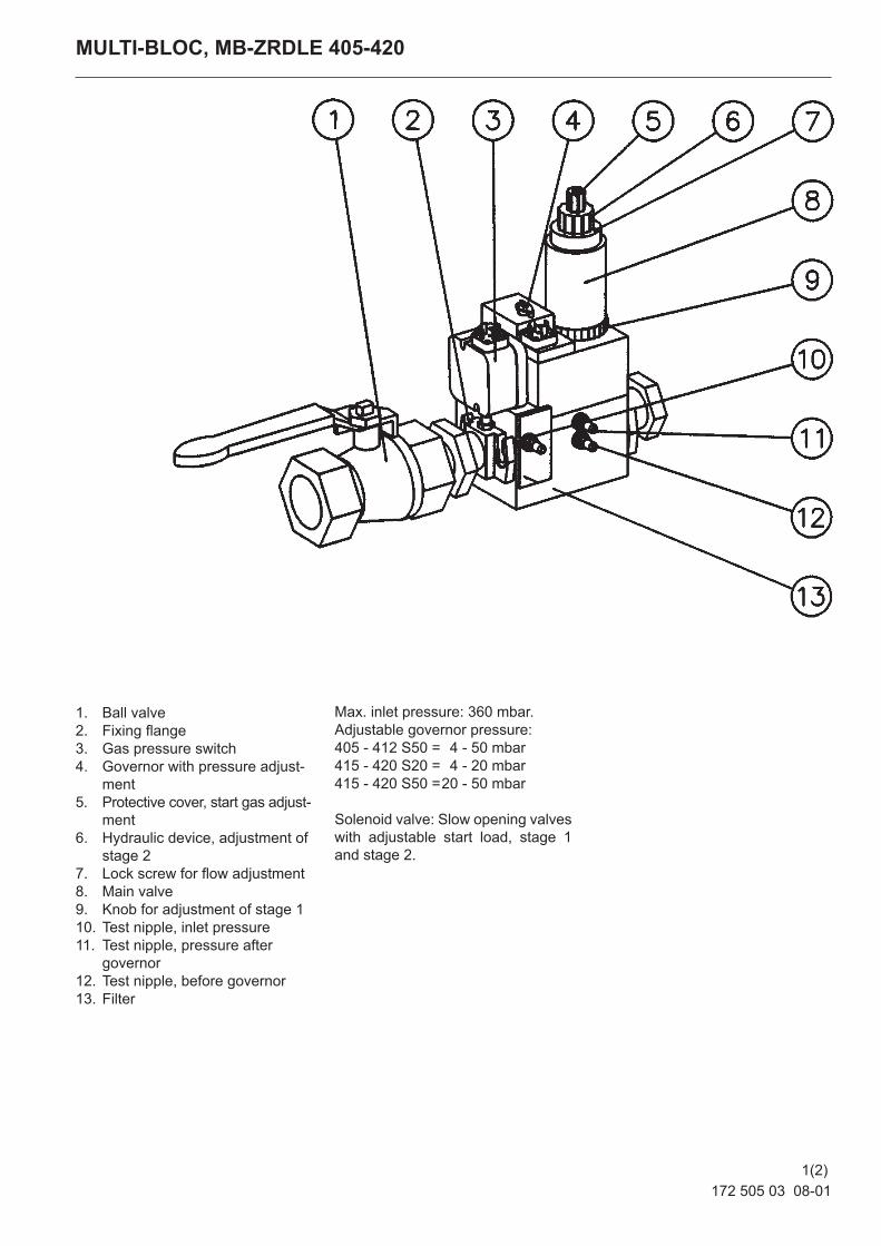
MULTI-BLOC, MB-ZRDLE 405-420
1. Ball valve2. Fixing flange3. Gas pressure switch4. Governor with pressure adjust-
ment5. Protective cover, start gas adjust-
ment6. Hydraulic device, adjustment of
stage 27. Lock screw for flow adjustment8. Main valve9. Knob for adjustment of stage 110. Test nipple, inlet pressure 11. Test nipple, pressure after
governor12. Test nipple, before governor13. Filter
Max. inlet pressure: 360 mbar. Adjustable governor pressure: 405 - 412 S50 = 4 - 50 mbar415 - 420 S20 = 4 - 20 mbar415 - 420 S50 = 20 - 50 mbar
Solenoid valve: Slow opening valves with adjustable start load, stage 1 and stage 2.
1(2)
172 505 03 08-01
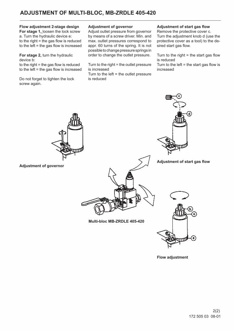
Flow adjustment 2-stage designFor stage 1, loosen the lock screw a. Turn the hydraulic device e:to the right = the gas flow is reducedto the left = the gas flow is increased
For stage 2, turn the hydraulic device b:to the right = the gas flow is reduced to the left = the gas flow is increased
Do not forget to tighten the lock screw again.
ADJUSTMENT OF MULTI-BLOC, MB-ZRDLE 405-420
Adjustment of governorAdjust outlet pressure from governor by means of a screw driver. Min. and max. outlet pressures correspond to appr. 60 turns of the spring. It is not possible to change pressure springs in order to change the outlet pressure.
Turn to the right = the outlet pressure is increasedTurn to the left = the outlet pressure is reduced
Adjustment of start gas flowRemove the protective cover c.Turn the adjustment knob d (use the protective cover as a tool) to the de-sired start gas flow.
Turn to the right = the start gas flow is reducedTurn to the left = the start gas flow is increased
Adjustment of governor
Multi-bloc MB-ZRDLE 405-420
Adjustment of start gas flow
Flow adjustment
2(2)
GENERAL INSTRUCTIONS
Adjustment of burnerThe burner is from the factory pre-set to an average value that must then be adjusted to the boiler in question.All burner adjustments must be made in accordance with boiler manu-facturers instructions. These must include the checking of flue gas temperatures, average water temperature and CO2 or O2 concentration.General instructionsThe installation of the gas burner must be carried out in accordance with current regulations and standards. The installers of gas burners should therefore be acquainted with all regu-lations and ensure that the installation complies with the requirements. The installation, mounting and adjustment should be made with the greatest care and only the correct gas should be used.Operating instructionsThe operating instructions accom-panying the burner should be left in a prominent position in the boiler room.InstructionsThe user should be thoroughly instructed in the function of the gas burner and the whole installation. The supplier must instruct the user.Inspection and maintenanceDaily inspection is advisable.Start upAfter the burner has been fitted to the boiler and the electric connection, the leakage control, the venting and the electric function test have been carried out, the burner will be ready for start-up.
Howerer, study the sections dealing with adjustments of multi-bloc, com-bustion air and combustion head.Open the ball valve and switch on the main switch. If the burner starts the actual adjustment can be made.Adjustment of burner headThe burner is equipped with an adjust-ment device changing the po si tion of the brake plate in the burner head. This is used to adjust the cor rect pressure drop over the com bus tion device in order to obtain a good pulsation free combustion.
Which position to use depends on input and overpressure in the boiler.
172 305 28 07-01
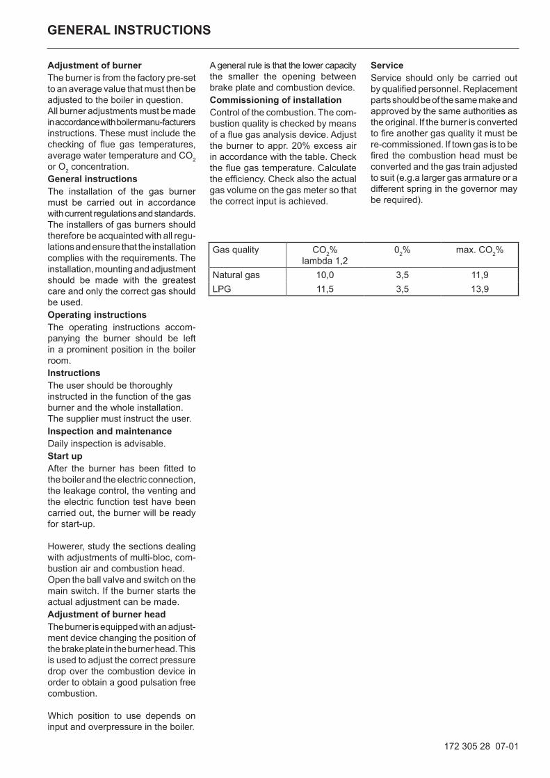
A general rule is that the lower capacity the smaller the opening between brake plate and combustion device.Commissioning of installationControl of the combustion. The com-bustion quality is checked by means of a flue gas analysis device. Adjust the burner to appr. 20% excess air in accordance with the table. Check the flue gas temperature. Calculate the efficiency. Check also the actual gas volume on the gas meter so that the correct input is achieved.
ServiceService should only be carried out by qualified personnel. Replacement parts should be of the same make and approved by the same authorities as the original. If the burner is converted to fire another gas quality it must be re-commissioned. If town gas is to be fired the combustion head must be converted and the gas train adjusted to suit (e.g.a larger gas armature or a different spring in the governor may be required).
Gas quality CO2% lambda 1,2
02% max. CO2%
Natural gas 10,0 3,5 11,9LPG 11,5 3,5 13,9
172 305 29 07-01
GENERAL INSTRUCTIONS
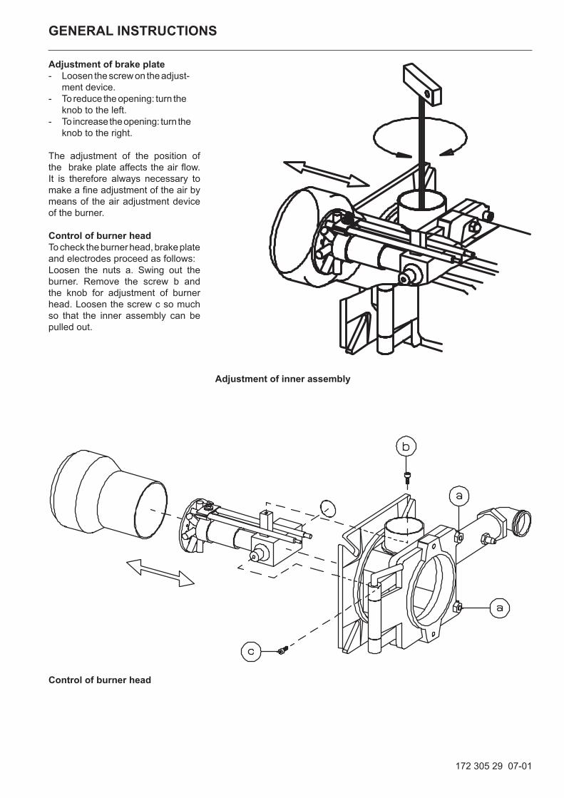
Adjustment of brake plate- Loosen the screw on the adjust- ment device.- To reduce the opening: turn the knob to the left.- To increase the opening: turn the knob to the right.
The adjustment of the position of the brake plate affects the air flow. It is therefore always necessary to make a fine adjustment of the air by means of the air adjustment device of the burner.
Control of burner headTo check the burner head, brake plate and electrodes proceed as follows:Loosen the nuts a. Swing out the burner. Remove the screw b and the knob for adjustment of burner head. Loosen the screw c so much so that the inner assembly can be pulled out.
Adjustment of inner assembly
Control of burner head
172 305 25 11-01
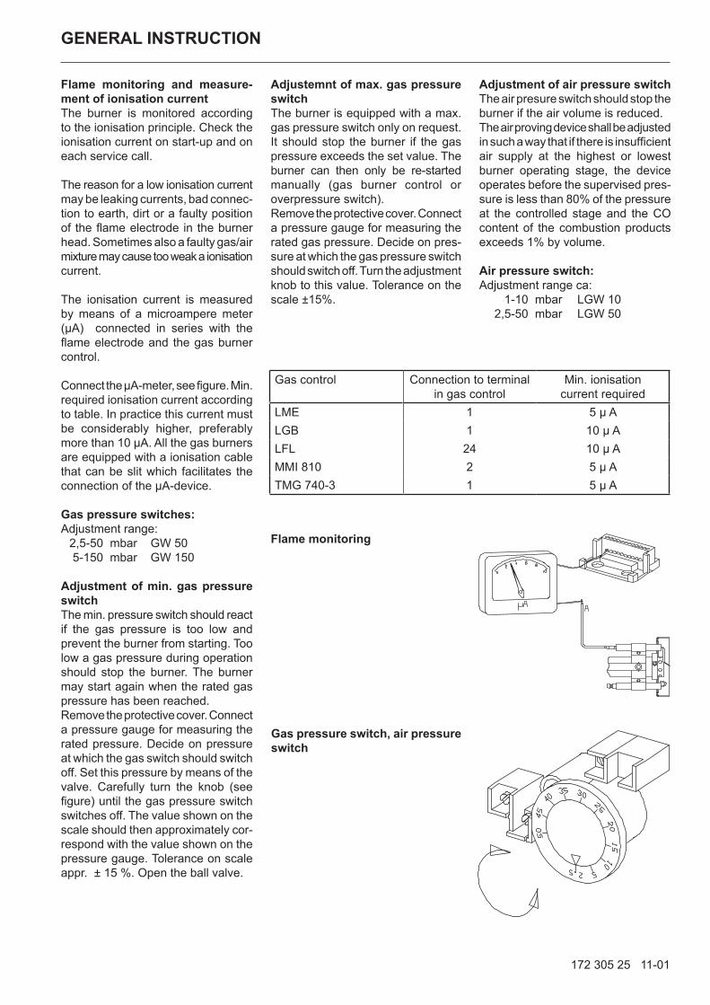
Flame monitoring and measure-ment of ionisation currentThe burner is monitored according to the ionisation principle. Check the ionisation current on start-up and on each service call.
The reason for a low ionisation current may be leaking currents, bad connec-tion to earth, dirt or a faulty position of the flame electrode in the burner head. Sometimes also a faulty gas/air mixture may cause too weak a ionisation current.
The ionisation current is measured by means of a microampere meter (µA) connected in series with the flame electrode and the gas burner control.
Connect the µA-meter, see figure. Min. required ionisation current according to table. In practice this current must be considerably higher, preferably more than 10 µA. All the gas burners are equipped with a ionisation cable that can be slit which facilitates the connection of the µA-device.
Gas pressure switches:Adjustment range: 2,5-50 mbar GW 50 5-150 mbar GW 150
Adjustment of min. gas pressure switchThe min. pressure switch should react if the gas pressure is too low and prevent the burner from starting. Too low a gas pressure during operation should stop the burner. The burner may start again when the rated gas pressure has been reached.Remove the protective cover. Connect a pressure gauge for measuring the rated pressure. Decide on pressure at which the gas switch should switch off. Set this pressure by means of the valve. Carefully turn the knob (see figure) until the gas pressure switch switches off. The value shown on the scale should then approximately cor-respond with the value shown on the pressure gauge. Tolerance on scale appr. ± 15 %. Open the ball valve.
GENERAL INSTRUCTION
Adjustemnt of max. gas pressure switchThe burner is equipped with a max. gas pressure switch only on request. It should stop the burner if the gas pressure exceeds the set value. The burner can then only be re-started manually (gas burner control or overpressure switch).Remove the protective cover. Connect a pressure gauge for measuring the rated gas pressure. Decide on pres-sure at which the gas pressure switch should switch off. Turn the adjustment knob to this value. Tolerance on the scale ±15%.
Adjustment of air pressure switchThe air presure switch should stop the burner if the air volume is reduced. The air proving device shall be adjusted in such a way that if there is insufficient air supply at the highest or lowest burner operating stage, the device operates before the supervised pres-sure is less than 80% of the pressure at the controlled stage and the CO content of the combustion products exceeds 1% by volume.
Air pressure switch:Adjustment range ca: 1-10 mbar LGW 10 2,5-50 mbar LGW 50
Flame monitoring
Gas pressure switch, air pressure switch
Gas control Connection to terminalin gas control
Min. ionisationcurrent required
LME 1 5 µ ALGB 1 10 µ ALFL 24 10 µ AMMI 810 2 5 µ ATMG 740-3 1 5 µ A
FINAL TEST OF THE INSTALLATION
172 305 17 07-01
– Make repeated start attempts to ensure that the adjustments function.
– Close the ball valve during operation to check that the gas switch switches off at the set value.
– Remove the hose for the air pressure switch to check that the burner locks out.
– Check that all protective covers and measurement nipples are mounted and fastened.
– Fill out necessary test reports.
– Instruct the persons in charge of the operation on the service and maintenance of the installa-tion and what to do should any troubles occur.
– Inspection and service must only be carried out by author-ized people.
Fault location, functional troublesTrouble free operation is dependent on three factors: electricity, gas and air supply. Should there be any changes in the ratio between these three factors there is a risk of break downs. It has been proved that most break downs are caused by simple faults. Before calling the service engineer, the following should therefore be checked:
– Is the gas cock open?
– Are all fuses in order and the current switched on?
– Are the thermostats correctly set?
– Are pressostats, overheating protection etc. in operating posi-tion and not locked-out?
– Is the gas pressure sufficient?
– Is the gas burner control in start position?
– Has the gas control or the motor protector locked out? - Reset.
– Is the circulation pump in opera-tion?
– Is there a supply of fresh air to the installation?
If integral components are of a different make from what is stated in this manual, see the enclosed loose-leaf.
170 091 16 08-01
Gas burner
FAULT LOCATION GUIDE
The basis for trouble free operation can only be ensured by the correct combined effect of the three factors:electricity, gas flow and combustion air. Should any of these factors change troubles may arise.
It has been proved that many troubles have rather sim-ple causes. Before calling the serviceman the following checks should be made:
1. Are the gas cocks of the installation open?2. Are the fuses in order and the current switched
on?3. Are the controls (room thermostat, boiler thermostat
etc.) correctly adjusted?4. Is the gas pressure to the burner sufficient?5. Is the gas relay of the burner ready for start and
not locked out?6. Is the air supply to the burner sufficient?
To facilitate fault location we have drawn up a scheme showing the most frequent faults in a gas burner instal-lation and the remedies.
REMEDY
The burner does not start
No gas Check that all gas cocks are open.
No voltage Check fuses, thermostats and electrical connections
The burner motor fails to start The thermal protection has locked out. Motor defective.
The gas relay is defective Replace
Burner motor is running but no ignition after the prepurge time has elapsed
No voltage on the terminals Check the contact. Replace faulty relay
The ignition electrodes in contact with each other or with earth
Adjust
The porcelain of the electrodes is broken Replace the electrodes
CAUSE
1(4)
170 091 16 08-01
The cable shoes have bad contact Improve the contact
The ignition cables are damaged Replace
The ignition transformer is damaged, no voltage on the secondary side
Replace the transformer
The ignition cable and the ionisation cable have been transposed.
Change
No flame establishment in spite of a trouble free start
The gas solenoid valve defective Replace
The gas solenoid valve does not open in spite of its obtaining voltage
Replace coil or the whole valve if necessary.
No voltage to the solenoid valve Check the contact
No electrical connection through the air pressure switch
Test the adjustment and the function of the air pressure switch
The starting load is not correctly adjusted Reduce or increase the gas supply, reduce the quantity of air
Gas relay defective Replace
Air pressure switch incorrectly adjusted or defective Check the adjustment and readjust.
No reponse as the cams of the servomotor are not correctly adjusted or out of position.
The burner locks out after the safety time has elapsed in spite of flame establishment
No ionisation current or the UV-cell in wrong position Adjust the ionisation electrode and the UV-cell, examine cables and connections.
The supervision part of the gas relay is defective Replace the relay
REMEDYCAUSE
2(4)
170 091 16 08-01
Voltage lower than 185 V Contact the electricity authorities.
The ignition electrodes are disturbing the ionisation current
Adjust the ignition electrodes, repole the ignitiontransformer if necessary.
Bad earthing Arrange for proper earthing.
Phase and neutral transposed See wiring diagram and change.
The burner locks out during pre-purge
Air pressure switch defective or incorrectly adjusted
The starting load is not correctly adjusted Reduce or increase the gas supply. Reduce the quantity of air.
The gas pressure is too low Increase the pressure. Contact the gas supply company if necessary.
Pulsations at start
The ignition electrodes are wrongly adjusted Readjust.
The gas pressure is too high Check and adjust by means of a pressure gauge and a pressure adjustment valve.
The flue gas side is blocked Check the chimney flue.
Pulsations during operation
The burner is not correctly adjusted Readjust
The burner is dirty Clean the burner.
Defective chimney Check and change the dimensions if necessary.
The burner is operating correctly but locking out now and then
The ionisation current is too low Check. Must be at least 4 µ A according to the relay manufacturer but should be 8-20 µ A.
The UV-cell is in a wrong position Adjust.
Voltage drop at certain times Must not drop more than 15% of the rated current. Con-tact the electricity authorities if necessary.
Air pressure switch defective or incorrectly adjusted
Spark-over in ignition electrodes Replace the electrodes
REMEDYCAUSE
3(4)
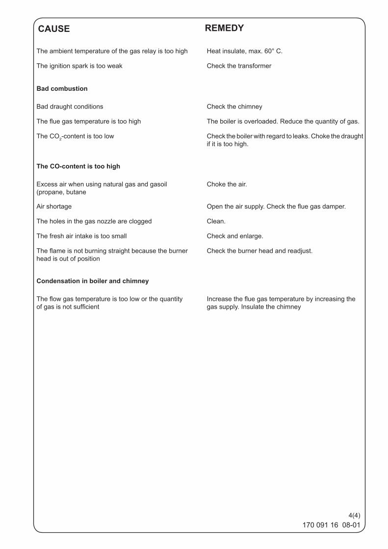
170 091 16 08-01
The ambient temperature of the gas relay is too high Heat insulate, max. 60° C.
The ignition spark is too weak Check the transformer
Bad combustion
Bad draught conditions Check the chimney
The flue gas temperature is too high The boiler is overloaded. Reduce the quantity of gas.
The CO2-content is too low Check the boiler with regard to leaks. Choke the draught if it is too high.
The CO-content is too high
Excess air when using natural gas and gasoil (propane, butane
Choke the air.
Air shortage Open the air supply. Check the flue gas damper.
The holes in the gas nozzle are clogged Clean.
The fresh air intake is too small Check and enlarge.
The flame is not burning straight because the burner head is out of position
Check the burner head and readjust.
Condensation in boiler and chimney
The flow gas temperature is too low or the quantity of gas is not sufficient
Increase the flue gas temperature by increasing the gas supply. Insulate the chimney
REMEDYCAUSE
4(4)
172 905 95 14-01
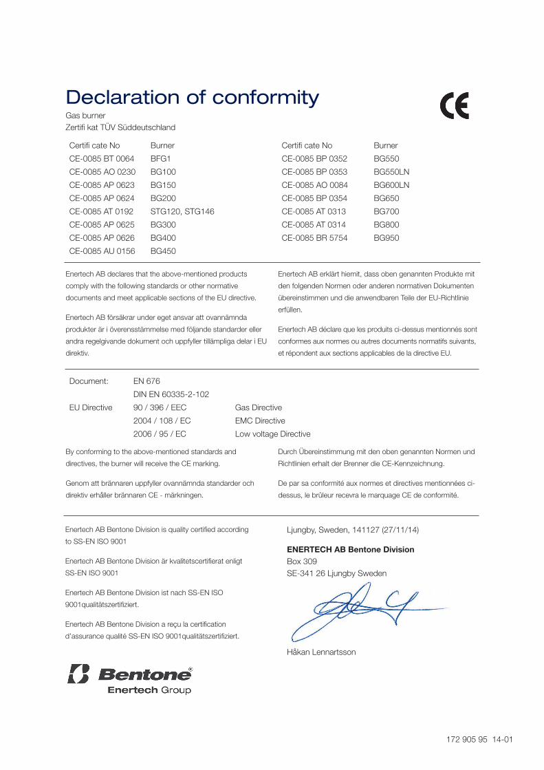
Declaration of conformityGas burner Zertifi kat TÜV Süddeutschland
Certifi cate No Burner Certifi cate No Burner
CE-0085 BT 0064 BFG1 CE-0085 BP 0352 BG550
CE-0085 AO 0230 BG100 CE-0085 BP 0353 BG550LN
CE-0085 AP 0623 BG150 CE-0085 AO 0084 BG600LN
CE-0085 AP 0624 BG200 CE-0085 BP 0354 BG650
CE-0085 AT 0192 STG120, STG146 CE-0085 AT 0313 BG700
CE-0085 AP 0625 BG300 CE-0085 AT 0314 BG800
CE-0085 AP 0626 BG400 CE-0085 BR 5754 BG950
CE-0085 AU 0156 BG450
Document: EN 676
DIN EN 60335-2-102
EU Directive 90 / 396 / EEC Gas Directive
2004 / 108 / EC EMC Directive
2006 / 95 / EC Low voltage Directive
By conforming to the above-mentioned standards and
directives, the burner will receive the CE marking.
Genom att brännaren uppfyller ovannämnda standarder och
direktiv erhåller brännaren CE - märkningen.
Durch Übereinstimmung mit den oben genannten Normen und
Richtlinien erhalt der Brenner die CE-Kennzeichnung.
De par sa conformité aux normes et directives mentionnées ci-
dessus, le brûleur recevra le marquage CE de conformité.
Ljungby, Sweden, 141127 (27/11/14)
ENERTECH AB Bentone Division Box 309 SE-341 26 Ljungby Sweden
Håkan Lennartsson
Enertech AB declares that the above-mentioned products
comply with the following standards or other normative
documents and meet applicable sections of the EU directive.
Enertech AB försäkrar under eget ansvar att ovannämnda
produkter är i överensstämmelse med följande standarder eller
andra regelgivande dokument och uppfyller tillämpliga delar i EU
direktiv.
Enertech AB erklärt hiemit, dass oben genannten Produkte mit
den folgenden Normen oder anderen normativen Dokumenten
übereinstimmen und die anwendbaren Teile der EU-Richtlinie
erfüllen.
Enertech AB déclare que les produits ci-dessus mentionnés sont
conformes aux normes ou autres documents normatifs suivants,
et répondent aux sections applicables de la directive EU.
Enertech AB Bentone Division is quality certified according
to SS-EN ISO 9001
Enertech AB Bentone Division är kvalitetscertifierat enligt
SS-EN ISO 9001
Enertech AB Bentone Division ist nach SS-EN ISO
9001qualitätszertifiziert.
Enertech AB Bentone Division a reçu la certification
d’assurance qualité SS-EN ISO 9001qualitätszertifiziert.
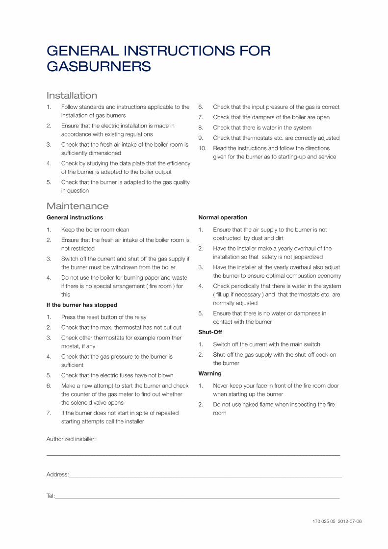
GENERAL INSTRUCTIONS FOR GASBURNERS
Installation1. Follow standards and instructions applicable to the
installation of gas burners
2. Ensure that the electric installation is made in accordance with existing regulations
3. Check that the fresh air intake of the boiler room is sufficiently dimensioned
4. Check by studying the data plate that the efficiency of the burner is adapted to the boiler output
5. Check that the burner is adapted to the gas quality in question
6. Check that the input pressure of the gas is correct
7. Check that the dampers of the boiler are open
8. Check that there is water in the system
9. Check that thermostats etc. are correctly adjusted
10. Read the instructions and follow the directions given for the burner as to starting-up and service
MaintenanceGeneral instructions
1. Keep the boiler room clean
2. Ensure that the fresh air intake of the boiler room is not restricted
3. Switch off the current and shut off the gas supply if the burner must be withdrawn from the boiler
4. Do not use the boiler for burning paper and waste if there is no special arrangement ( fire room ) for this
If the burner has stopped
1. Press the reset button of the relay
2. Check that the max. thermostat has not cut out
3. Check other thermostats for example room ther mostat, if any
4. Check that the gas pressure to the burner is sufficient
5. Check that the electric fuses have not blown
6. Make a new attempt to start the burner and check the counter of the gas meter to find out whether the solenoid valve opens
7. If the burner does not start in spite of repeated starting attempts call the installer
Normal operation
1. Ensure that the air supply to the burner is not obstructed by dust and dirt
2. Have the installer make a yearly overhaul of the installation so that safety is not jeopardized
3. Have the installer at the yearly overhaul also adjust the burner to ensure optimal combustion economy
4. Check periodically that there is water in the system ( fill up if necessary ) and that thermostats etc. are normally adjusted
5. Ensure that there is no water or dampness in contact with the burner
Shut-Off
1. Switch off the current with the main switch
2. Shut-off the gas supply with the shut-off cock on the burner
Warning
1. Never keep your face in front of the fire room door when starting up the burner
2. Do not use naked flame when inspecting the fire room
Authorized installer:
____________________________________________________________________________________________________
Address:_____________________________________________________________________________________________
Tel:_________________________________________________________________________________________________
170 025 05 2012-07-06
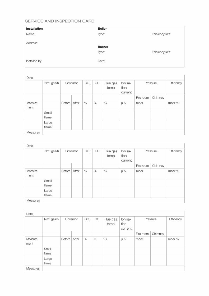
SERVICE AND INSPECTION CARD
Installation Boiler
Name: Type: Efficiency kW:
Address:Burner
Type: Efficiency kW:
Installed by: Date:
Date
Nm3 gas/h Governor CO2 CO Flue gas temp
Ionisa-tion current
Pressure Efficiency
Fire room Chimney
Measure- ment
Before After % % °C µ A mbar mbar %
Smallflame
Largeflame
Measures
Date
Nm3 gas/h Governor CO2 CO Flue gas temp
Ionisa-tion current
Pressure Efficiency
Fire room Chimney
Measure- ment
Before After % % °C µ A mbar mbar %
Smallflame
Largeflame
Measures
Date
Nm3 gas/h Governor CO2 CO Flue gas temp
Ionisa-tion current
Pressure Efficiency
Fire room Chimney
Measure- ment
Before After % % °C µ A mbar mbar %
Smallflame
Largeflame
Measures


Enertech AB. P.O Box 309, SE-341 26 Ljungby.
www.bentone.se, www.bentone.com