Embed Size (px)
Citation preview
Series 300 API Filter Press ® Instruction Manual Part No. 300010001EA Rev. D

TABLE OF CONTENTS Section 1 Description .................................................................1 2 Safety Considerations ..................................................3 3 Filter Press Pressure Sources ......................................5 4 Standard Filter Press Test Procedures ........................ 13 5 Fread Filter Press Test Procedures ............................. 15 6 Care of Equipment ..................................................... 19 7 Parts List.................................................................. 21 Figure 1 CO2 Cartridge Holder Assembly ....................................4 2 No. 30200 - Filter Press with Nitrogen Cylinder Pressure Source .........................................................6 3 No. 30300 - Dead-Weight Hydraulic Filter Press.............9 4 No. 33500 - Dead Weight Hydraulic Assembly ...............9 5 No. 33800 - CO2 Pressure Assembly, Exploded View ... 11 6 No. 34265 - Pressure Regulator Assembly................... 12 7 Filter Press and Cell Assembly, Exploded View ........... 14 8 Filtration Reduction Evaluation Device - (FREAD)....... 17 9 No. 30000 - Filter Press, Standard Frame.................... 20 10 No. 30101 - Filter Press w/N2...................................... 22 11 No. 30201 - Filter Press w/CO2 ................................... 24 12 No. 30800 - Filter press Wall Mount Frame w/CO2........ 27 13 No. 30502 - Filter Press, Wall Mount in Case............... 28 14 No. 31100 - Filter Press Six-Cell with Manifold ............. 30 15 No. 33801 - CO2 Pressure Assembly with Top Cap....... 33
1
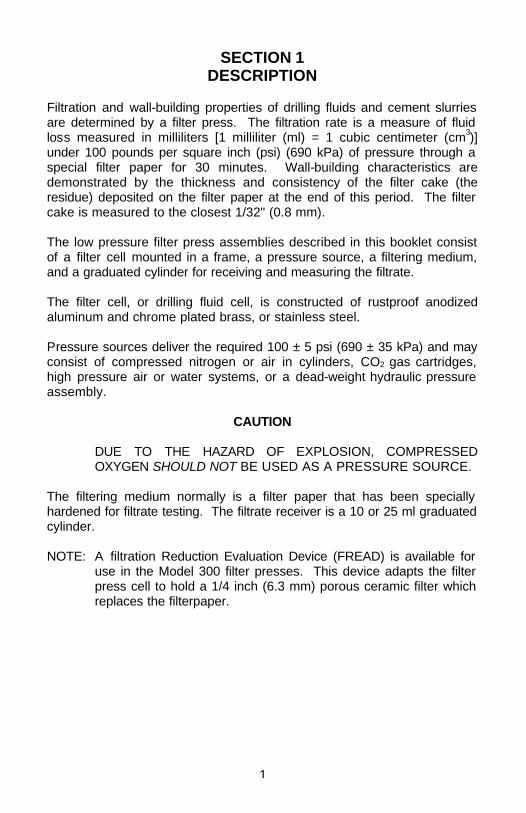
SECTION 1 DESCRIPTION Filtration and wall-building properties of drilling fluids and cement slurries are determined by a filter press. The filtration rate is a measure of fluid loss measured in milliliters [1 milliliter (ml) = 1 cubic centimeter (cm3)] under 100 pounds per square inch (psi) (690 kPa) of pressure through a special filter paper for 30 minutes. Wall-building characteristics are demonstrated by the thickness and consistency of the filter cake (the residue) deposited on the filter paper at the end of this period. The filter cake is measured to the closest 1/32" (0.8 mm). The low pressure filter press assemblies described in this booklet consist of a filter cell mounted in a frame, a pressure source, a filtering medium, and a graduated cylinder for receiving and measuring the filtrate. The filter cell, or drilling fluid cell, is constructed of rustproof anodized aluminum and chrome plated brass, or stainless steel. Pressure sources deliver the required 100 ± 5 psi (690 ± 35 kPa) and may consist of compressed nitrogen or air in cylinders, CO2 gas cartridges, high pressure air or water systems, or a dead-weight hydraulic pressure assembly. CAUTION DUE TO THE HAZARD OF EXPLOSION, COMPRESSED
OXYGEN SHOULD NOT BE USED AS A PRESSURE SOURCE. The filtering medium normally is a filter paper that has been specially hardened for filtrate testing. The filtrate receiver is a 10 or 25 ml graduated cylinder. NOTE: A filtration Reduction Evaluation Device (FREAD) is available for
use in the Model 300 filter presses. This device adapts the filter press cell to hold a 1/4 inch (6.3 mm) porous ceramic filter which replaces the filterpaper.

2
3
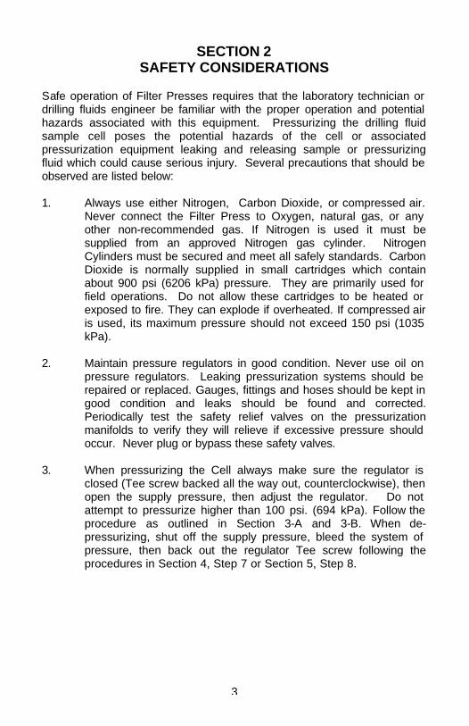
SECTION 2 SAFETY CONSIDERATIONS Safe operation of Filter Presses requires that the laboratory technician or drilling fluids engineer be familiar with the proper operation and potential hazards associated with this equipment. Pressurizing the drilling fluid sample cell poses the potential hazards of the cell or associated pressurization equipment leaking and releasing sample or pressurizing fluid which could cause serious injury. Several precautions that should be observed are listed below: 1. Always use either Nitrogen, Carbon Dioxide, or compressed air.
Never connect the Filter Press to Oxygen, natural gas, or any other non-recommended gas. If Nitrogen is used it must be supplied from an approved Nitrogen gas cylinder. Nitrogen Cylinders must be secured and meet all safely standards. Carbon Dioxide is normally supplied in small cartridges which contain about 900 psi (6206 kPa) pressure. They are primarily used for field operations. Do not allow these cartridges to be heated or exposed to fire. They can explode if overheated. If compressed air is used, its maximum pressure should not exceed 150 psi (1035 kPa).
2. Maintain pressure regulators in good condition. Never use oil on
pressure regulators. Leaking pressurization systems should be repaired or replaced. Gauges, fittings and hoses should be kept in good condition and leaks should be found and corrected. Periodically test the safety relief valves on the pressurization manifolds to verify they will relieve if excessive pressure should occur. Never plug or bypass these safety valves.
3. When pressurizing the Cell always make sure the regulator is
closed (Tee screw backed all the way out, counterclockwise), then open the supply pressure, then adjust the regulator. Do not attempt to pressurize higher than 100 psi. (694 kPa). Follow the procedure as outlined in Section 3-A and 3-B. When de-pressurizing, shut off the supply pressure, bleed the system of pressure, then back out the regulator Tee screw following the procedures in Section 4, Step 7 or Section 5, Step 8.
4
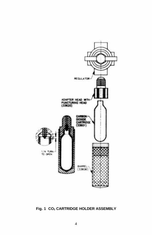
Fig. 1 CO2 CARTRIDGE HOLDER ASSEMBLY
5
SECTION 3 FILTER PRESS PRESSURE SOURCES A. CO2 CARTRIDGE PRESSURE SOURCE Follow this procedure to pressurize the filter press with a CO2
cartridge pressure source (Refer to Fig. 1) 1. Remove the barrel from the CO2 pressuring assembly and
insert a fresh CO2 cartridge. 2. After making sure the safety bleeder valve is closed, and
the regulator adjusting screw is backed out to the closed position (maximum outward), turn the barrel loosely with the fingers until first contact with the puncturing pin is felt.
3. Advance the holder an additional 1/4 turn. The puncture
pin, shown in Fig. 1, seals when the cartridge seats. 4. Screw the adjusting screw into the regulator to apply 100
± 5 psi (690 kPa) pressure to the filter cell as indicated by the
test-pressure gauge. Start 30-minute timing now. CAUTION WHEN USING SYSTEMS WITH CO2 CARTRIDGES AS A
PRESSURE SOURCE, NO INLET PRESSURE GAUGE OR VALVE IS USED. USE CARE WHEN REPLACING SPENT CO2 CARTRIDGES. THERE COULD BE SOME PRESSURE LEFT IN THE CARTRIDGE. KEEP CO2 CARTRIDGES AWAY FROM EXTREME HEAT.
6
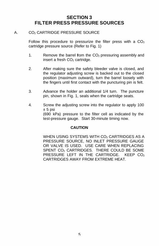
Fig. 2 - NO. 30200 FILTER PRESS WITH NITROGEN CYLINDER PRESSURE SOURCE
7
B. NITROGEN CYLINDER PRESSURE SOURCE Follow this procedure to pressurize the filter press with a Nitrogen
cylinder pressure source (Refer to the assembly in Fig. 2): 1. With the regulator adjusting screw backed out to the
closed position (maximum outward), slowly open the pressure valve on the cylinder. The inlet pressure gauge should show the cylinder pressure. Be sure this is greater than 100 psi, (690 kPa).
2. Be sure the hose between the cylinder regulator and the
cell is connected, all fittings are tight, and the safety-bleeder valve is closed.
3. Screw the regulator adjusting screw into the regulator to
apply 100 ± 5 psi (690 kPa) pressure to the filter cell, as indicated by the test-pressure gauge. Start 30-minute timing now.
CAUTION ALWAYS SCREW THE REGULATOR ADJUSTING
SCREW TO ITS MAXIMUM OUTWARD POSITION BEFORE OPENING THE RELEASE VALVE ON THE PRESSURE SOURCE. IF THE FULL PRESSURE OF THE PRESSURE SOURCE IS RELEASED TO AN OPEN REGULATOR, THE REGULATOR IS PUT UNDER A SEVERE STRAIN. IF THIS CAUSES THE REGULATOR TO FAIL, THE FULL TANK PRESSURE IS RELEASED TO THE FILTER PRESS AND IT MAY BE DAMAGED. AS AN ADDED PRECAUTION, A SAFETY BLEEDER VALVE, THAT RELEASES AT APPROXIMATELY 170 PSI, IS PLACED IN THE SYSTEM BETWEEN THE REGULATOR AND THE FILTER PRESS.
8
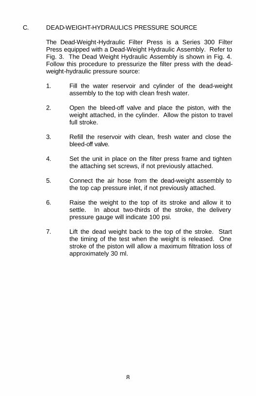
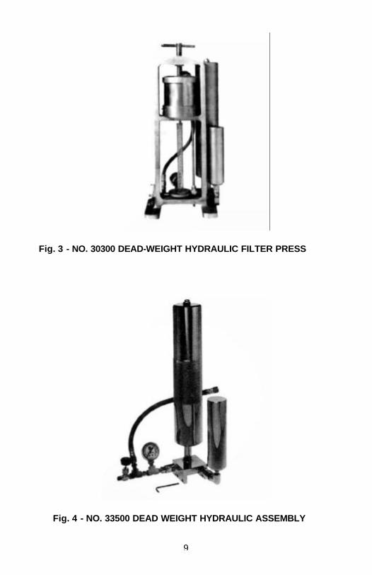
C. DEAD-WEIGHT-HYDRAULICS PRESSURE SOURCE The Dead-Weight-Hydraulic Filter Press is a Series 300 Filter
Press equipped with a Dead-Weight Hydraulic Assembly. Refer to Fig. 3. The Dead Weight Hydraulic Assembly is shown in Fig. 4. Follow this procedure to pressurize the filter press with the dead-weight-hydraulic pressure source:
1. Fill the water reservoir and cylinder of the dead-weight
assembly to the top with clean fresh water. 2. Open the bleed-off valve and place the piston, with the
weight attached, in the cylinder. Allow the piston to travel full stroke.
3. Refill the reservoir with clean, fresh water and close the
bleed-off valve. 4. Set the unit in place on the filter press frame and tighten
the attaching set screws, if not previously attached. 5. Connect the air hose from the dead-weight assembly to
the top cap pressure inlet, if not previously attached. 6. Raise the weight to the top of its stroke and allow it to
settle. In about two-thirds of the stroke, the delivery pressure gauge will indicate 100 psi.
7. Lift the dead weight back to the top of the stroke. Start
the timing of the test when the weight is released. One stroke of the piston will allow a maximum filtration loss of approximately 30 ml.
9
Fig. 3 - NO. 30300 DEAD-WEIGHT HYDRAULIC FILTER PRESS
Fig. 4 - NO. 33500 DEAD WEIGHT HYDRAULIC ASSEMBLY
10
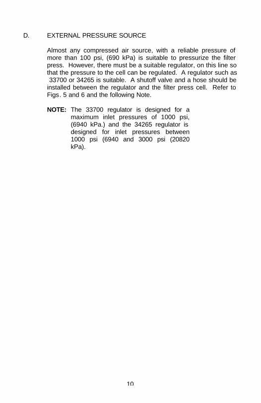
D. EXTERNAL PRESSURE SOURCE Almost any compressed air source, with a reliable pressure of
more than 100 psi, (690 kPa) is suitable to pressurize the filter press. However, there must be a suitable regulator, on this line so that the pressure to the cell can be regulated. A regulator such as 33700 or 34265 is suitable. A shutoff valve and a hose should be installed between the regulator and the filter press cell. Refer to Figs. 5 and 6 and the following Note.
NOTE: The 33700 regulator is designed for a
maximum inlet pressures of 1000 psi, (6940 kPa.) and the 34265 regulator is designed for inlet pressures between 1000 psi (6940 and 3000 psi (20820 kPa).
11
Fig. 5 - NO. 33800 CO2 PRESSURE ASSEMBLY,EXPLODED VIEW
12
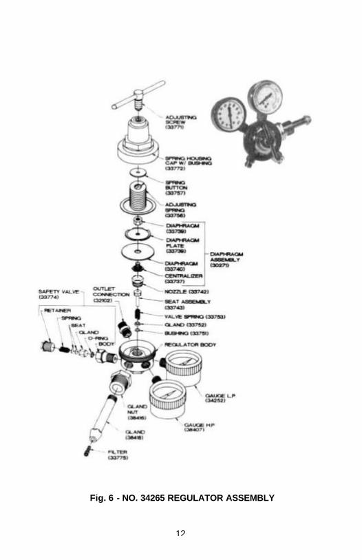
Fig. 6 - NO. 34265 REGULATOR ASSEMBLY
13
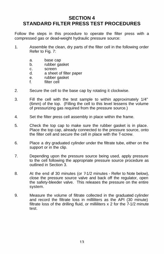
SECTION 4 STANDARD FILTER PRESS TEST PROCEDURES Follow the steps in this procedure to operate the filter press with a compressed gas or dead-weight hydraulic pressure source: 1. Assemble the clean, dry parts of the filter cell in the following order
Refer to Fig. 7: a. base cap b. rubber gasket c. screen d. a sheet of filter paper e. rubber gasket f. filter cell 2. Secure the cell to the base cap by rotating it clockwise. 3. Fill the cell with the test sample to within approximately 1/4"
(6mm) of the top. (Filling the cell to this level lessens the volume of pressurizing gas required from the pressure source.)
4. Set the filter press cell assembly in place within the frame. 5. Check the top cap to make sure the rubber gasket is in place.
Place the top cap, already connected to the pressure source, onto the filter cell and secure the cell in place with the T-screw.
6. Place a dry graduated cylinder under the filtrate tube, either on the
support or in the clip. 7. Depending upon the pressure source being used, apply pressure
to the cell following the appropriate pressure source procedure as outlined in Section 3.
8. At the end of 30 minutes (or 7-1/2 minutes - Refer to Note below),
close the pressure source valve and back off the regulator, open the safety-bleeder valve. This releases the pressure on the entire system.
9. Measure the volume of filtrate collected in the graduated cylinder
and record the filtrate loss in milliliters as the API (30 minute) filtrate loss of the drilling fluid, or milliliters x 2 for the 7-1/2 minute test.
14
NOTE: The amount of filtrate collected after 7-1/2 minutes can be noted and, when this amount is multiplied by two, it will give a rough estimate of the amount that will be collected in 30 minutes. The estimated valve is usually one or more milliliters short of the actual valve and this estimation procedure should not be attempted on drilling fluids having a filtrate loss of less than 5 ml in the 7-1/2 minute period.
10. Loosen the T-screw, remove the cell top, and then remove the cell
from the frame. 11. Discard the drilling fluid. 12. Disassemble the filter cell and carefully remove the filter cake and
filter paper from the base cap. 13. With a gentle steam of water (or, in the case of oil drilling fluids,
with clean base oil), carefully wash excess drilling fluid from the cake.
14. Measure and record the thickness of the filter cake to the nearest
1/32" (0.8 mm). 15. If desired, record properties of the filter cake such as texture,
hardness, flexibility, etc.
Fig. 7 - FILTER PRESS AND CELL ASSEMBLY,\ EXPLODED VIEW
15
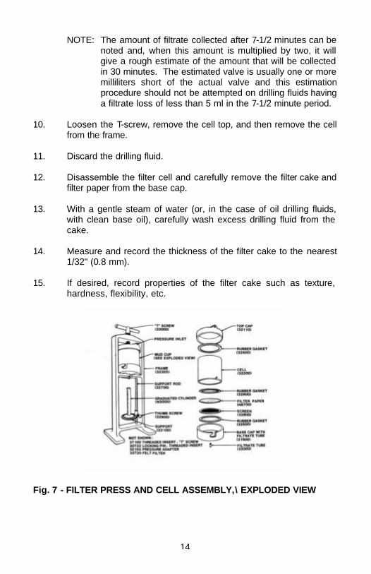
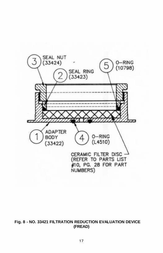
SECTION 5 FREAD FILTER PRESS TEST PROCEDURES Follow this modified procedure if the FREAD ceramic disc adapter is to be used. Either compressed gas or the dead-weight-hydraulic unit can be used. 1. Assemble the Filtration Reduction Evaluation Device as follows,
Refer to Fig. 8: a. Assemble the selected porosity ceramic filter disc into the
Body Adapter (1). b. Assemble "O" ring seal (5) into the Body Adapter. c. Install Ring Seal (2) into Body Adapter fitting it over the
"O" ring. d. Screw the Seal Nut (3) onto the Body Adapter (1) and
tighten hand tight. e. Install "O" Ring (4) on the outside bottom of the Body
Adapter. 2. Assemble the dry parts of the filter cell in the following order.
Refer to Fig. 7 and Fig. 8 omitting filter paper and screen from Fig. 7.
a. base cap b. rubber gasket c. FREAD assembly. Refer to Procedure 1 above. d. rubber gasket e. filter cell Secure the cell to the base cap by rotating it
clockwise. 3. Fill the cell with the test sample to within approximately 1/4"
(6mm) of the top. (Filling the cell to this level lessens the pressure volume required from the pressure source.)
4. Set the filter press cell assembly in place within the frame. 5. Check the top cap to make sure the rubber gasket is in place.
Place the top cap, already connected to the pressure source, onto the filter cell and secure the cell in place with the T-screw.
16
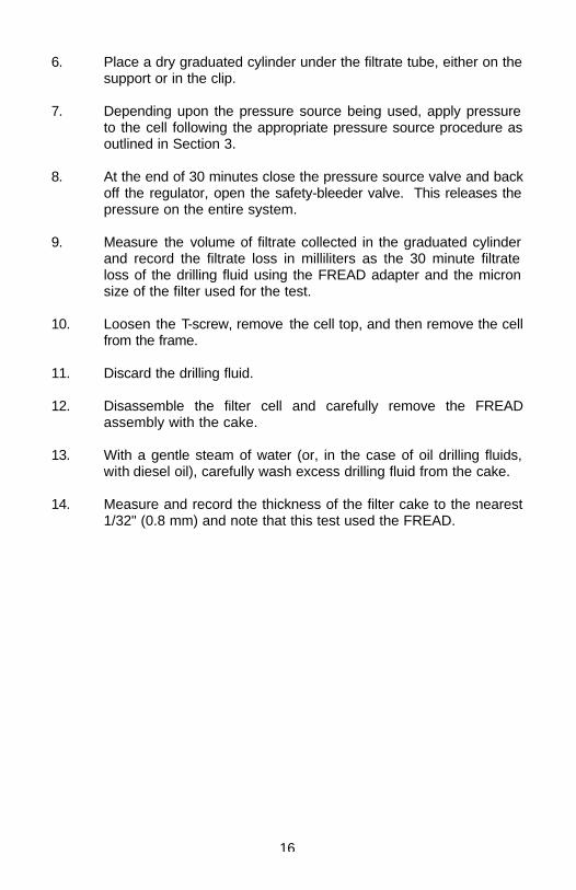
6. Place a dry graduated cylinder under the filtrate tube, either on the support or in the clip.
7. Depending upon the pressure source being used, apply pressure
to the cell following the appropriate pressure source procedure as outlined in Section 3.
8. At the end of 30 minutes close the pressure source valve and back
off the regulator, open the safety-bleeder valve. This releases the pressure on the entire system.
9. Measure the volume of filtrate collected in the graduated cylinder
and record the filtrate loss in milliliters as the 30 minute filtrate loss of the drilling fluid using the FREAD adapter and the micron size of the filter used for the test.
10. Loosen the T-screw, remove the cell top, and then remove the cell
from the frame. 11. Discard the drilling fluid. 12. Disassemble the filter cell and carefully remove the FREAD
assembly with the cake. 13. With a gentle steam of water (or, in the case of oil drilling fluids,
with diesel oil), carefully wash excess drilling fluid from the cake. 14. Measure and record the thickness of the filter cake to the nearest
1/32" (0.8 mm) and note that this test used the FREAD.
17
Fig. 8 - NO. 33421 FILTRATION REDUCTION EVALUATION DEVICE (FREAD)

18
19
SECTION 6 CARE OF EQUIPMENT A. Cleaning After each use, the filter press cell should be disassembled and
cleaned of all drilling fluid by washing and thoroughly rinsing. Wipe off the rest of the filter press, and dry all parts completely. Replace the filter paper on the screen, and assembly the end cap onto the cell. Loosely reassemble the cell onto the frame for storage.
B. Pressure Regulator Maintenance and Repair Most regulator troubles are caused by leaking fittings or faulty pins
and seats. Rarely does a diaphragm rupture. If regulator will not hold pressure, check the fittings which are screwed into it. This is done by applying pressure to the system and looking for escaping gas in the form of bubbles. There are two methods of doing this. One method is to apply soap suds to the fitting areas, the other is to carefully immerse all but the pressure gauge in a container of water. If leaks are apparent, disassemble and apply tape thread sealant to the threads.
CAUTION DO NOT USE OIL BASED THREAD DOPE OR OIL
WHEN ASSEMBLING ANY REGULATOR. Replacing the seat and pin. If regulator connections do not leak, the seat and pin probably
need replacement. Use the following procedure. Refer to items on Fig. 5 and 6.
1. Using a wrench on the hex of the spring case, unscrew
the spring case. All parts down to and including the diaphragm will remain in the spring case.
2. Remove the thrust plate.
20
3. Unscrew the retainer and remove the seat with the pin. 4. Clean and inspect the regulator for evidence of dirt or
drilling fluid in the regulator body. An outlet filter (33720) is available to prevent this problem.
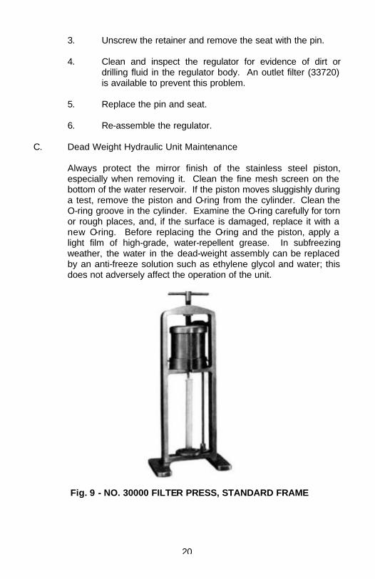
5. Replace the pin and seat. 6. Re-assemble the regulator. C. Dead Weight Hydraulic Unit Maintenance Always protect the mirror finish of the stainless steel piston,
especially when removing it. Clean the fine mesh screen on the bottom of the water reservoir. If the piston moves sluggishly during a test, remove the piston and O-ring from the cylinder. Clean the O-ring groove in the cylinder. Examine the O-ring carefully for torn or rough places, and, if the surface is damaged, replace it with a new O-ring. Before replacing the O-ring and the piston, apply a light film of high-grade, water-repellent grease. In subfreezing weather, the water in the dead-weight assembly can be replaced by an anti-freeze solution such as ethylene glycol and water; this does not adversely affect the operation of the unit.
Fig. 9 - NO. 30000 FILTER PRESS, STANDARD FRAME
21
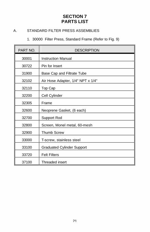
SECTION 7 PARTS LIST A. STANDARD FILTER PRESS ASSEMBLIES 1. 30000 Filter Press, Standard Frame (Refer to Fig. 9)
PART NO. DESCRIPTION
30001 Instruction Manual
30722 Pin for Insert
31900 Base Cap and Filtrate Tube
32102 Air Hose Adapter, 1/4" NPT x 1/4"
32110 Top Cap
32200 Cell Cylinder
32305 Frame
32600 Neoprene Gasket, (6 each)
32700 Support Rod
32800 Screen, Monel metal, 60-mesh
32900 Thumb Screw
33000 T-screw, stainless steel
33100 Graduated Cylinder Support
33720 Felt Filters
37100 Threaded insert
22
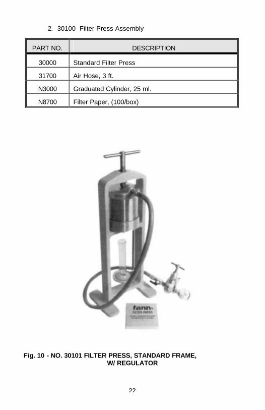
2. 30100 Filter Press Assembly
PART NO. DESCRIPTION
30000 Standard Filter Press
31700 Air Hose, 3 ft.
N3000 Graduated Cylinder, 25 ml.
N8700 Filter Paper, (100/box)
Fig. 10 - NO. 30101 FILTER PRESS, STANDARD FRAME, W/ REGULATOR
23
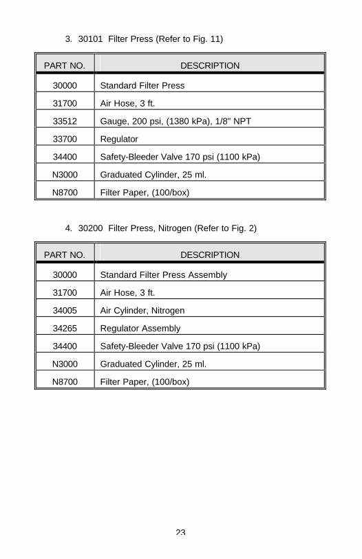
3. 30101 Filter Press (Refer to Fig. 11)
PART NO. DESCRIPTION
30000 Standard Filter Press
31700 Air Hose, 3 ft.
33512 Gauge, 200 psi, (1380 kPa), 1/8" NPT
33700 Regulator
34400 Safety-Bleeder Valve 170 psi (1100 kPa)
N3000 Graduated Cylinder, 25 ml.
N8700 Filter Paper, (100/box)
4. 30200 Filter Press, Nitrogen (Refer to Fig. 2)
PART NO. DESCRIPTION
30000 Standard Filter Press Assembly
31700 Air Hose, 3 ft.
34005 Air Cylinder, Nitrogen
34265 Regulator Assembly
34400 Safety-Bleeder Valve 170 psi (1100 kPa)
N3000 Graduated Cylinder, 25 ml.
N8700 Filter Paper, (100/box)
24
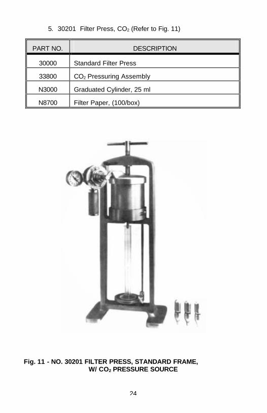
5. 30201 Filter Press, CO2 (Refer to Fig. 11)
PART NO. DESCRIPTION
30000 Standard Filter Press
33800 CO2 Pressuring Assembly
N3000 Graduated Cylinder, 25 ml
N8700 Filter Paper, (100/box)
Fig. 11 - NO. 30201 FILTER PRESS, STANDARD FRAME, W/ CO2 PRESSURE SOURCE
25
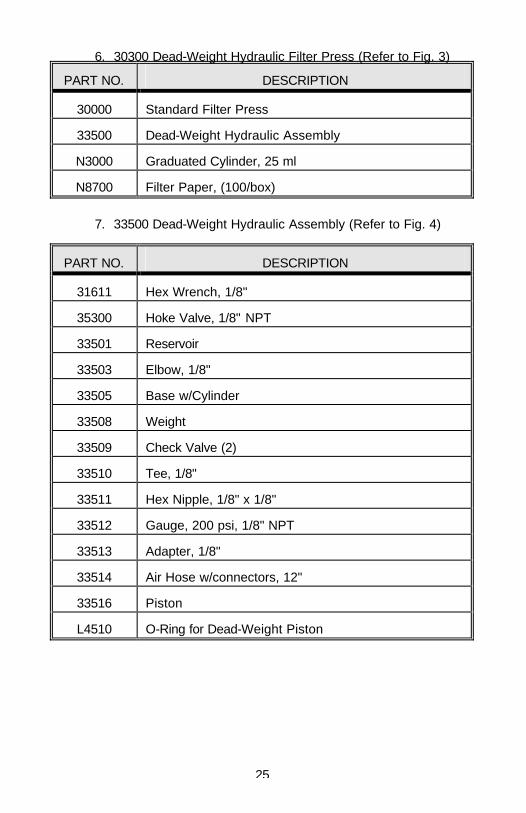
6. 30300 Dead-Weight Hydraulic Filter Press (Refer to Fig. 3)
PART NO. DESCRIPTION
30000 Standard Filter Press
33500 Dead-Weight Hydraulic Assembly
N3000 Graduated Cylinder, 25 ml
N8700 Filter Paper, (100/box)
7. 33500 Dead-Weight Hydraulic Assembly (Refer to Fig. 4)
PART NO. DESCRIPTION
31611 Hex Wrench, 1/8"
35300 Hoke Valve, 1/8" NPT
33501 Reservoir
33503 Elbow, 1/8"
33505 Base w/Cylinder
33508 Weight
33509 Check Valve (2)
33510 Tee, 1/8"
33511 Hex Nipple, 1/8" x 1/8"
33512 Gauge, 200 psi, 1/8" NPT
33513 Adapter, 1/8"
33514 Air Hose w/connectors, 12"
33516 Piston
L4510 O-Ring for Dead-Weight Piston
26
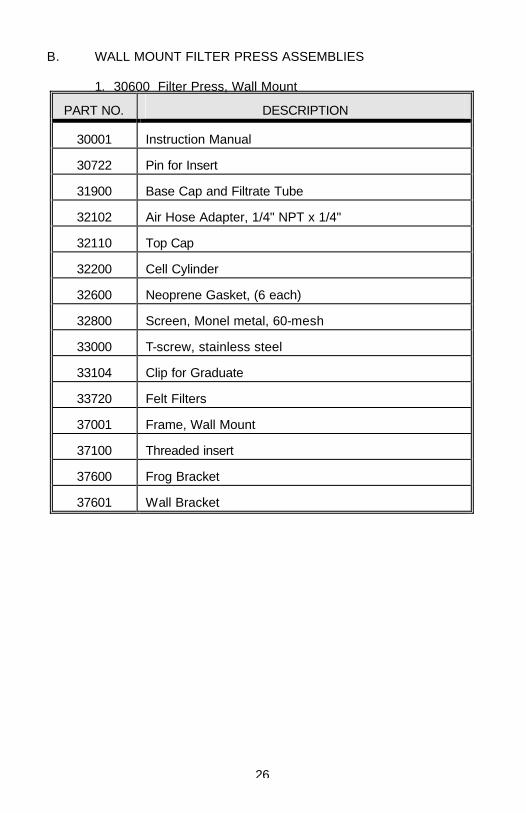
B. WALL MOUNT FILTER PRESS ASSEMBLIES 1. 30600 Filter Press, Wall Mount
PART NO. DESCRIPTION
30001 Instruction Manual
30722 Pin for Insert
31900 Base Cap and Filtrate Tube
32102 Air Hose Adapter, 1/4" NPT x 1/4"
32110 Top Cap
32200 Cell Cylinder
32600 Neoprene Gasket, (6 each)
32800 Screen, Monel metal, 60-mesh
33000 T-screw, stainless steel
33104 Clip for Graduate
33720 Felt Filters
37001 Frame, Wall Mount
37100 Threaded insert
37600 Frog Bracket
37601 Wall Bracket
27
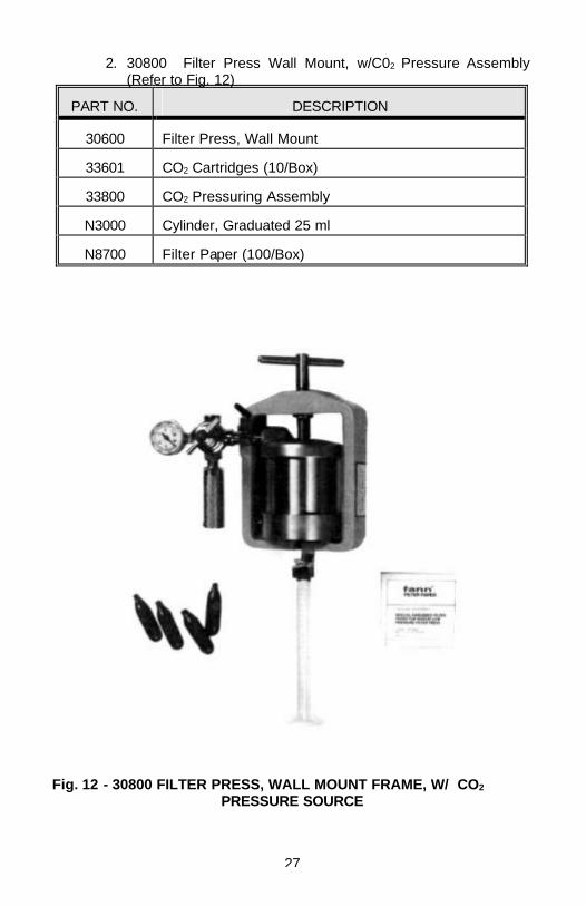
2. 30800 Filter Press Wall Mount, w/C02 Pressure Assembly (Refer to Fig. 12)
PART NO. DESCRIPTION
30600 Filter Press, Wall Mount
33601 CO2 Cartridges (10/Box)
33800 CO2 Pressuring Assembly
N3000 Cylinder, Graduated 25 ml
N8700 Filter Paper (100/Box)
Fig. 12 - 30800 FILTER PRESS, WALL MOUNT FRAME, W/ CO2 PRESSURE SOURCE
28
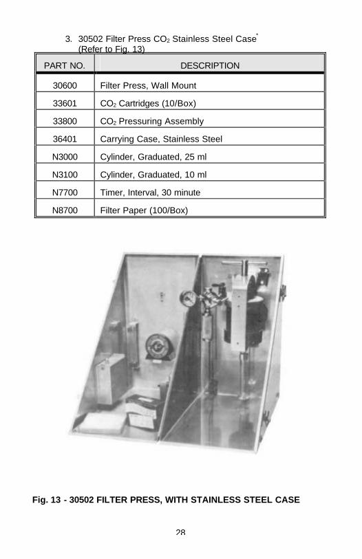
3. 30502 Filter Press CO2 Stainless Steel Case* (Refer to Fig. 13)
PART NO. DESCRIPTION
30600 Filter Press, Wall Mount
33601 CO2 Cartridges (10/Box)
33800 CO2 Pressuring Assembly
36401 Carrying Case, Stainless Steel
N3000 Cylinder, Graduated, 25 ml
N3100 Cylinder, Graduated, 10 ml
N7700 Timer, Interval, 30 minute
N8700 Filter Paper (100/Box)
Fig. 13 - 30502 FILTER PRESS, WITH STAINLESS STEEL CASE
29
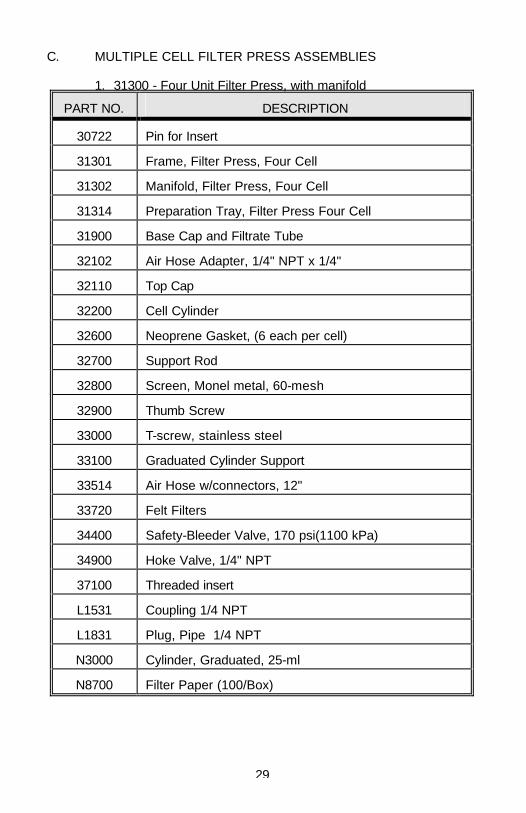
C. MULTIPLE CELL FILTER PRESS ASSEMBLIES 1. 31300 - Four Unit Filter Press, with manifold
PART NO. DESCRIPTION
30722 Pin for Insert
31301 Frame, Filter Press, Four Cell
31302 Manifold, Filter Press, Four Cell
31314 Preparation Tray, Filter Press Four Cell
31900 Base Cap and Filtrate Tube
32102 Air Hose Adapter, 1/4" NPT x 1/4"
32110 Top Cap
32200 Cell Cylinder
32600 Neoprene Gasket, (6 each per cell)
32700 Support Rod
32800 Screen, Monel metal, 60-mesh
32900 Thumb Screw
33000 T-screw, stainless steel
33100 Graduated Cylinder Support
33514 Air Hose w/connectors, 12"
33720 Felt Filters
34400 Safety-Bleeder Valve, 170 psi(1100 kPa)
34900 Hoke Valve, 1/4" NPT
37100 Threaded insert
L1531 Coupling 1/4 NPT
L1831 Plug, Pipe 1/4 NPT
N3000 Cylinder, Graduated, 25-ml
N8700 Filter Paper (100/Box)
30
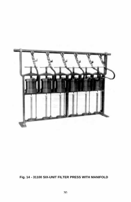
Fig. 14 - 31100 SIX-UNIT FILTER PRESS WITH MANIFOLD
31
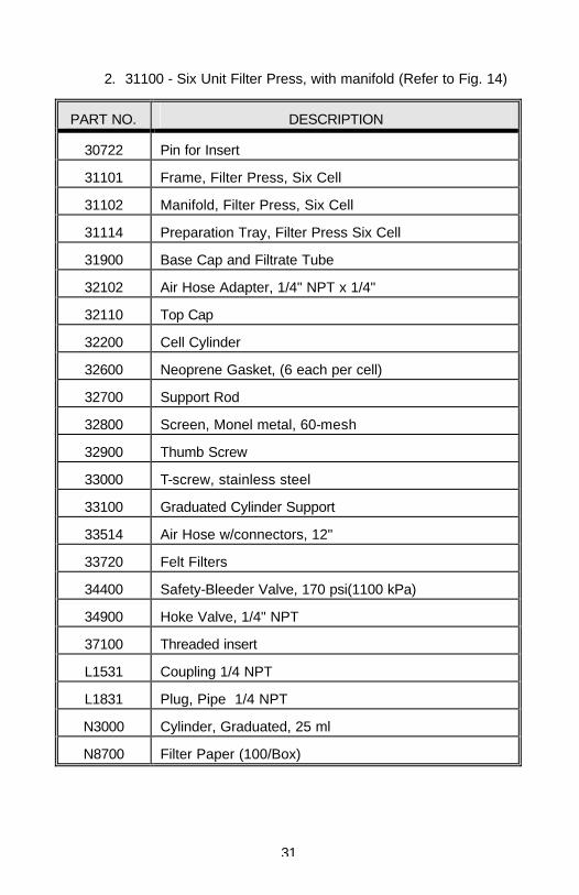
2. 31100 - Six Unit Filter Press, with manifold (Refer to Fig. 14)
PART NO. DESCRIPTION
30722 Pin for Insert
31101 Frame, Filter Press, Six Cell
31102 Manifold, Filter Press, Six Cell
31114 Preparation Tray, Filter Press Six Cell
31900 Base Cap and Filtrate Tube
32102 Air Hose Adapter, 1/4" NPT x 1/4"
32110 Top Cap
32200 Cell Cylinder
32600 Neoprene Gasket, (6 each per cell)
32700 Support Rod
32800 Screen, Monel metal, 60-mesh
32900 Thumb Screw
33000 T-screw, stainless steel
33100 Graduated Cylinder Support
33514 Air Hose w/connectors, 12"
33720 Felt Filters
34400 Safety-Bleeder Valve, 170 psi(1100 kPa)
34900 Hoke Valve, 1/4" NPT
37100 Threaded insert
L1531 Coupling 1/4 NPT
L1831 Plug, Pipe 1/4 NPT
N3000 Cylinder, Graduated, 25 ml
N8700 Filter Paper (100/Box)
32
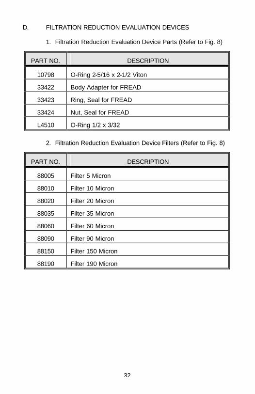
D. FILTRATION REDUCTION EVALUATION DEVICES 1. Filtration Reduction Evaluation Device Parts (Refer to Fig. 8)
PART NO. DESCRIPTION
10798 O-Ring 2-5/16 x 2-1/2 Viton
33422 Body Adapter for FREAD
33423 Ring, Seal for FREAD
33424 Nut, Seal for FREAD
L4510 O-Ring 1/2 x 3/32
2. Filtration Reduction Evaluation Device Filters (Refer to Fig. 8)
PART NO. DESCRIPTION
88005 Filter 5 Micron
88010 Filter 10 Micron
88020 Filter 20 Micron
88035 Filter 35 Micron
88060 Filter 60 Micron
88090 Filter 90 Micron
88150 Filter 150 Micron
88190 Filter 190 Micron
33
E. CO2 PRESSURING EQUIPMENT 1. 33800 CO2 Pressuring Assembly (Refer to Fig. 5)
PART NO. DESCRIPTION
33512 Gauge, 200 psi, 1-1/2" dia., 1/8 NPT
33601 CO2 Cartridges (10/box)
33606 Barrel for CO2 Cartridge
33620 Adapting Head with Puncture Pin
33700 Regulator
34400 Safety-Bleeder Valve, 170 psi
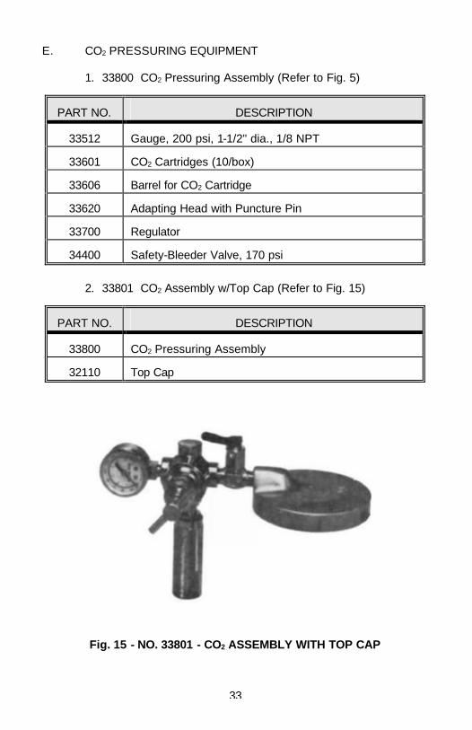
2. 33801 CO2 Assembly w/Top Cap (Refer to Fig. 15)
PART NO. DESCRIPTION
33800 CO2 Pressuring Assembly
32110 Top Cap
Fig. 15 - NO. 33801 - CO2 ASSEMBLY WITH TOP CAP
34
3. Accessories For CO2 Assembly
PART NO. DESCRIPTION
33610 Adapter (for external pressure supply)
L3706 Gauge, 200 psi, 1-1/2" dia., 1/8 NPT back conn.
4. 33700 Pressure Regulator, CO2 (Refer to Fig. 5)
PART NO. DESCRIPTION
33702 Seat
33704 Diaphragm
33705 Adjusting Screw, Spring Case
33709 Thrust Plate
33716 Spring Button
33717 Adjusting Spring
33718 Diaphragm Plate
33719 Slip Ring
33720 Output Filter
33725 Screens (2)
33770 Regulator Repair Kit consisting of: Retainer Pin O-Ring Seat Seat Holder Spring Spring Guide
(Continued) 35
F. NITROGEN PRESSURING SYSTEMS 1. 34265 Regulator, Nitrogen, with Gauges, (Refer to Fig. 6)
PART NO. DESCRIPTION
33771 Adjusting Screw
33772 Spring Housing Cap w/Bushing
33757 Spring Button
33756 Adjusting Spring
33755 Slip Ring
30271 Diaphragm Assembly
33738 Diaphragm Nut
33739 Diaphragm Plate
33740 Diaphragm
33737 Centralizer
33742 Nozzle
33744 Gasket
33743 Seat Assembly
33753 Valve Spring
33752 Gland
33751 Friction Washer
--- Body
38407 Gauge, 3000 psi
34252 Gauge, 200 psi
32102 Outlet Connection
38416 Inlet Nut
36
PART NO. DESCRIPTION
38418 Inlet Swivel
33775 Filter
33774 Safety Valve Consisting of: Body Friction Washer Gasket Gland Seat Spring Retainer
2. Nitrogen Supply System
PART NO. DESCRIPTION
34005 Cylinder, Nitrogen, (4" Dia. Size D)
34265 Regulator, Nitrogen, w/Gauges (Fig. 6)
34400 Safety Bleeder Valve, 170 psi (1180 kPa)
34900 Needle Valve, Male 1/4 NPT
35300 Needle Valve, Male 1/8 NPT
31700 Air Hose, 3 Ft., w/Connectors
31800 Air Hose, 6 Ft., w/Connectors
33610 Adapter, CO2 to Air Hose
37400 Speed Coupler or Air Hose
37500 Speed Connector for Coupler
34800 Wrench, 10 inch Adjustable
37
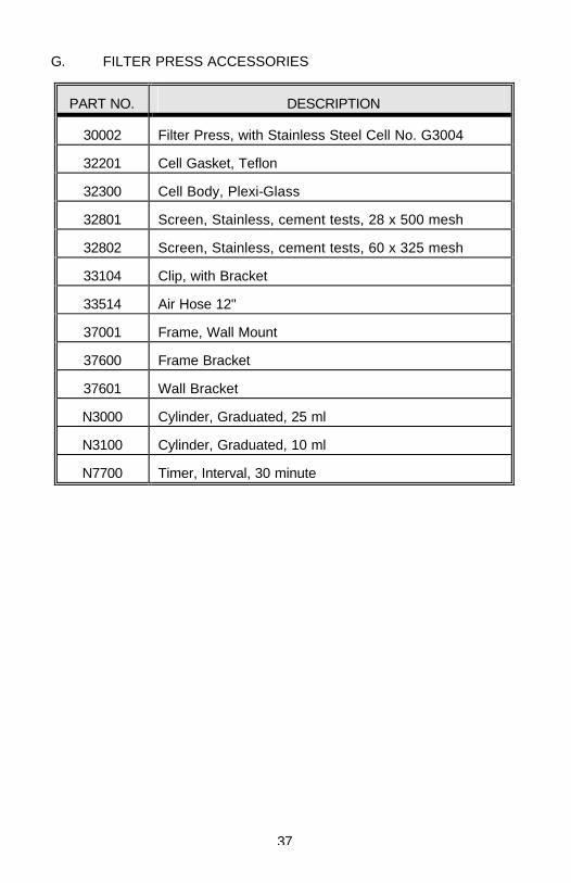
G. FILTER PRESS ACCESSORIES
PART NO. DESCRIPTION
30002 Filter Press, with Stainless Steel Cell No. G3004
32201 Cell Gasket, Teflon
32300 Cell Body, Plexi-Glass
32801 Screen, Stainless, cement tests, 28 x 500 mesh
32802 Screen, Stainless, cement tests, 60 x 325 mesh
33104 Clip, with Bracket
33514 Air Hose 12"
37001 Frame, Wall Mount
37600 Frame Bracket
37601 Wall Bracket
N3000 Cylinder, Graduated, 25 ml
N3100 Cylinder, Graduated, 10 ml
N7700 Timer, Interval, 30 minute


![Change-Over Inline Filter AFLD to API 614 up to 1700 l/min ... · Change-Over Inline Filter AFLD to API 614 ... ZU U-Stamp (approval to ASME ... pressure vessel Nominal [l] size Pressure](https://img.pdfslide.us/doc/110x75/5af637ee7f8b9a154c90ceb6/change-over-inline-filter-afld-to-api-614-up-to-1700-lmin-inline-filter-afld.jpg)