Embed Size (px)
Citation preview
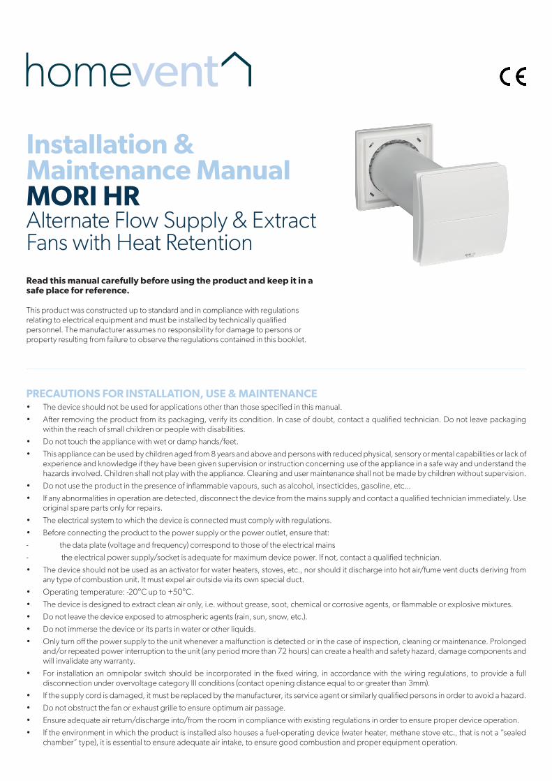
Installation & Maintenance ManualMORI HR
Alternate Flow Supply & ExtractFans with Heat RetentionRead this manual carefully before using the product and keep it in a safe place for reference. This product was constructed up to standard and in compliance with regulations relating to electrical equipment and must be installed by technically qualified personnel. The manufacturer assumes no responsibility for damage to persons or property resulting from failure to observe the regulations contained in this booklet.
PRECAUTIONS FOR INSTALLATION, USE & MAINTENANCE• The device should not be used for applications other than those specified in this manual.
• After removing the product from its packaging, verify its condition. In case of doubt, contact a qualified technician. Do not leave packaging within the reach of small children or people with disabilities.
• Do not touch the appliance with wet or damp hands/feet.
• This appliance can be used by children aged from 8 years and above and persons with reduced physical, sensory or mental capabilities or lack of experience and knowledge if they have been given supervision or instruction concerning use of the appliance in a safe way and understand the hazards involved. Children shall not play with the appliance. Cleaning and user maintenance shall not be made by children without supervision.
• Do not use the product in the presence of inflammable vapours, such as alcohol, insecticides, gasoline, etc...
• If any abnormalities in operation are detected, disconnect the device from the mains supply and contact a qualified technician immediately. Use original spare parts only for repairs.
• The electrical system to which the device is connected must comply with regulations.
• Before connecting the product to the power supply or the power outlet, ensure that:
- the data plate (voltage and frequency) correspond to those of the electrical mains
- the electrical power supply/socket is adequate for maximum device power. If not, contact a qualified technician.
• The device should not be used as an activator for water heaters, stoves, etc., nor should it discharge into hot air/fume vent ducts deriving from any type of combustion unit. It must expel air outside via its own special duct.
• Operating temperature: -20°C up to +50°C.
• The device is designed to extract clean air only, i.e. without grease, soot, chemical or corrosive agents, or flammable or explosive mixtures.
• Do not leave the device exposed to atmospheric agents (rain, sun, snow, etc.).
• Do not immerse the device or its parts in water or other liquids.
• Only turn off the power supply to the unit whenever a malfunction is detected or in the case of inspection, cleaning or maintenance. Prolonged and/or repeated power interruption to the unit (any period more than 72 hours) can create a health and safety hazard, damage components and will invalidate any warranty.
• For installation an omnipolar switch should be incorporated in the fixed wiring, in accordance with the wiring regulations, to provide a full disconnection under overvoltage category III conditions (contact opening distance equal to or greater than 3mm).
• If the supply cord is damaged, it must be replaced by the manufacturer, its service agent or similarly qualified persons in order to avoid a hazard.
• Do not obstruct the fan or exhaust grille to ensure optimum air passage.
• Ensure adequate air return/discharge into/from the room in compliance with existing regulations in order to ensure proper device operation.
• If the environment in which the product is installed also houses a fuel-operating device (water heater, methane stove etc., that is not a “sealed chamber” type), it is essential to ensure adequate air intake, to ensure good combustion and proper equipment operation.
2.
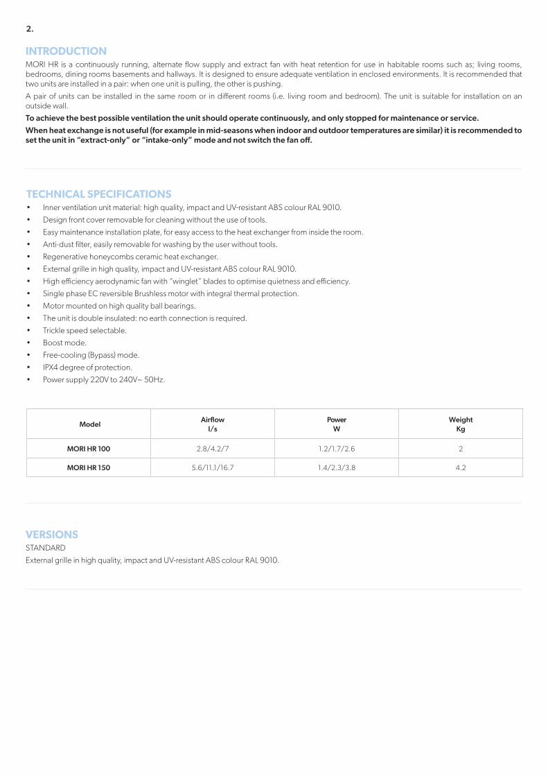
INTRODUCTIONMORI HR is a continuously running, alternate flow supply and extract fan with heat retention for use in habitable rooms such as; living rooms, bedrooms, dining rooms basements and hallways. It is designed to ensure adequate ventilation in enclosed environments. It is recommended that two units are installed in a pair: when one unit is pulling, the other is pushing.
A pair of units can be installed in the same room or in different rooms (i.e. living room and bedroom). The unit is suitable for installation on an outside wall.
To achieve the best possible ventilation the unit should operate continuously, and only stopped for maintenance or service.
When heat exchange is not useful (for example in mid-seasons when indoor and outdoor temperatures are similar) it is recommended to set the unit in “extract-only” or “intake-only” mode and not switch the fan off.
VERSIONSSTANDARD
External grille in high quality, impact and UV-resistant ABS colour RAL 9010.
TECHNICAL SPECIFICATIONS• Inner ventilation unit material: high quality, impact and UV-resistant ABS colour RAL 9010.
• Design front cover removable for cleaning without the use of tools.
• Easy maintenance installation plate, for easy access to the heat exchanger from inside the room.
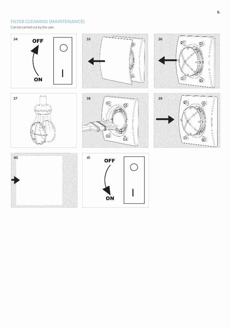
• Anti-dust filter, easily removable for washing by the user without tools.
• Regenerative honeycombs ceramic heat exchanger.
• External grille in high quality, impact and UV-resistant ABS colour RAL 9010.
• High efficiency aerodynamic fan with “winglet” blades to optimise quietness and efficiency.
• Single phase EC reversible Brushless motor with integral thermal protection.
• Motor mounted on high quality ball bearings.
• The unit is double insulated: no earth connection is required.
• Trickle speed selectable.
• Boost mode.
• Free-cooling (Bypass) mode.
• IPX4 degree of protection.
• Power supply 220V to 240V~ 50Hz.
ModelAirflow
l/s Power
W Weight
Kg
MORI HR 100 2.8/4.2/7 1.2/1.7/2.6 2
MORI HR 150 5.6/11.1/16.7 1.4/2.3/3.8 4.2
3.
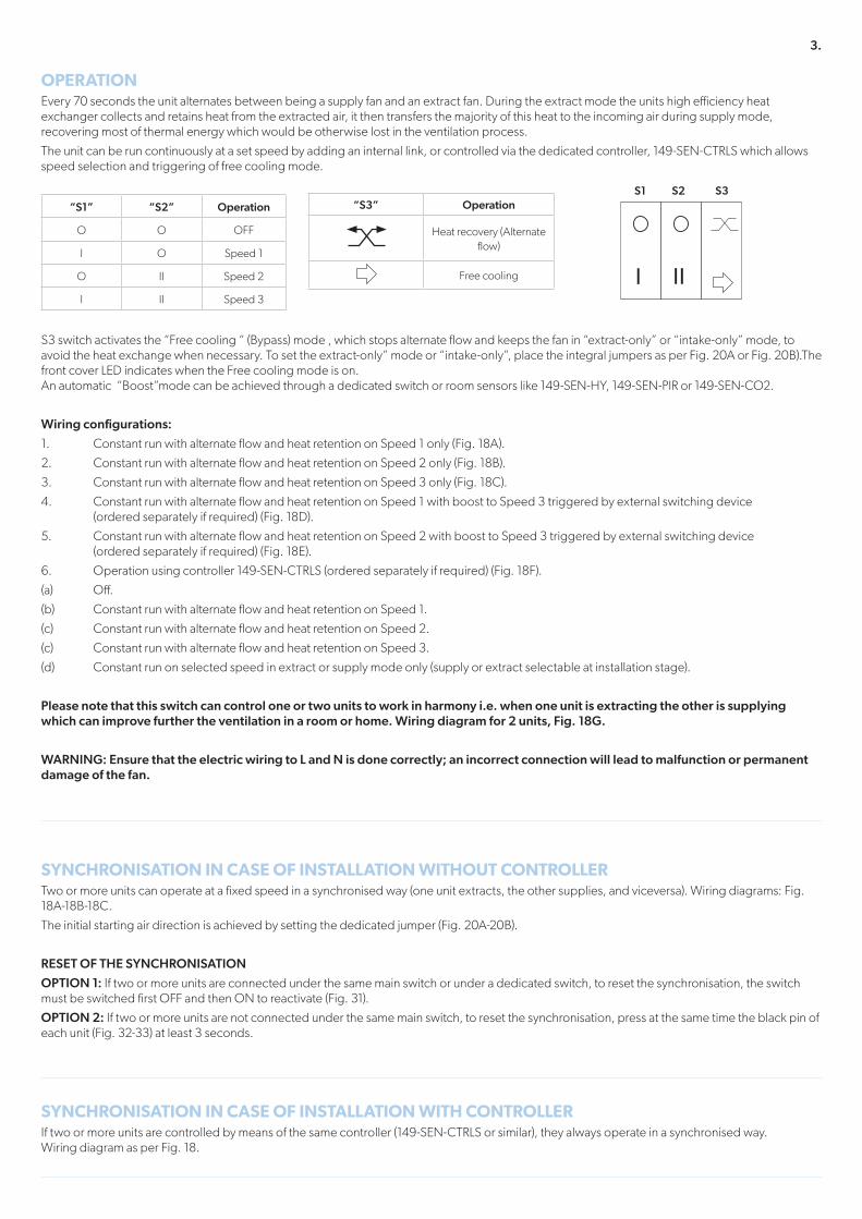
OPERATIONEvery 70 seconds the unit alternates between being a supply fan and an extract fan. During the extract mode the units high efficiency heat exchanger collects and retains heat from the extracted air, it then transfers the majority of this heat to the incoming air during supply mode, recovering most of thermal energy which would be otherwise lost in the ventilation process.
The unit can be run continuously at a set speed by adding an internal link, or controlled via the dedicated controller, 149-SEN-CTRLS which allows speed selection and triggering of free cooling mode.
S3 switch activates the “Free cooling “ (Bypass) mode , which stops alternate flow and keeps the fan in “extract-only” or “intake-only” mode, to avoid the heat exchange when necessary. To set the extract-only” mode or “intake-only”, place the integral jumpers as per Fig. 20A or Fig. 20B).The front cover LED indicates when the Free cooling mode is on. An automatic “Boost”mode can be achieved through a dedicated switch or room sensors like 149-SEN-HY, 149-SEN-PIR or 149-SEN-CO2.
Wiring configurations:
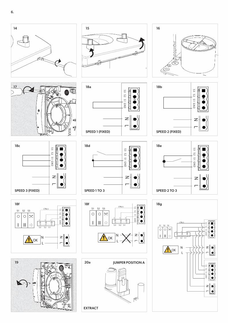
1. Constant run with alternate flow and heat retention on Speed 1 only (Fig. 18A).
2. Constant run with alternate flow and heat retention on Speed 2 only (Fig. 18B).
3. Constant run with alternate flow and heat retention on Speed 3 only (Fig. 18C).
4. Constant run with alternate flow and heat retention on Speed 1 with boost to Speed 3 triggered by external switching device (ordered separately if required) (Fig. 18D).
5. Constant run with alternate flow and heat retention on Speed 2 with boost to Speed 3 triggered by external switching device (ordered separately if required) (Fig. 18E).
6. Operation using controller 149-SEN-CTRLS (ordered separately if required) (Fig. 18F).
(a) Off.
(b) Constant run with alternate flow and heat retention on Speed 1.
(c) Constant run with alternate flow and heat retention on Speed 2.
(c) Constant run with alternate flow and heat retention on Speed 3.
(d) Constant run on selected speed in extract or supply mode only (supply or extract selectable at installation stage).
Please note that this switch can control one or two units to work in harmony i.e. when one unit is extracting the other is supplying which can improve further the ventilation in a room or home. Wiring diagram for 2 units, Fig. 18G.
WARNING: Ensure that the electric wiring to L and N is done correctly; an incorrect connection will lead to malfunction or permanent damage of the fan.
“S1” “S2” Operation
O O OFF
I O Speed 1
O II Speed 2
I II Speed 3
S1
III
“S3” Operation
Heat recovery (Alternate flow)
Free cooling
SYNCHRONISATION IN CASE OF INSTALLATION WITHOUT CONTROLLERTwo or more units can operate at a fixed speed in a synchronised way (one unit extracts, the other supplies, and viceversa). Wiring diagrams: Fig. 18A-18B-18C.
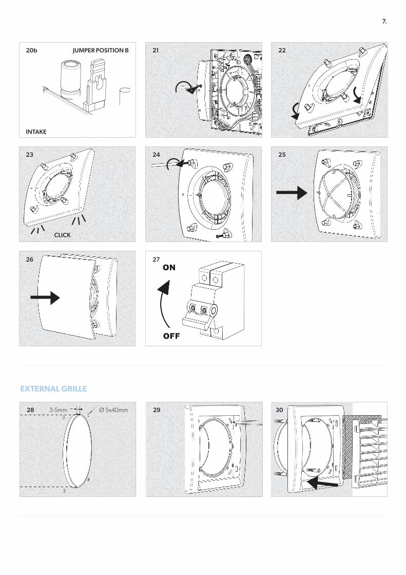
The initial starting air direction is achieved by setting the dedicated jumper (Fig. 20A-20B).
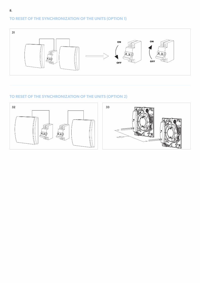
RESET OF THE SYNCHRONISATION
OPTION 1: If two or more units are connected under the same main switch or under a dedicated switch, to reset the synchronisation, the switch must be switched first OFF and then ON to reactivate (Fig. 31).
OPTION 2: If two or more units are not connected under the same main switch, to reset the synchronisation, press at the same time the black pin of each unit (Fig. 32-33) at least 3 seconds.
SYNCHRONISATION IN CASE OF INSTALLATION WITH CONTROLLERIf two or more units are controlled by means of the same controller (149-SEN-CTRLS or similar), they always operate in a synchronised way. Wiring diagram as per Fig. 18.
S2 S3
4.
MAINTENANCE AND SERVICEMaintenance can be carried out by the user as indicated at page 11.
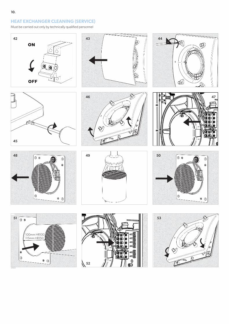
Service must be perfmormed only by technically qualified personnel in accordance with local rules and regulations. Make sure that the mains supply to the unit is disconnected (page 12). Cleaning of the heat exchanger can be performed from outside as well.
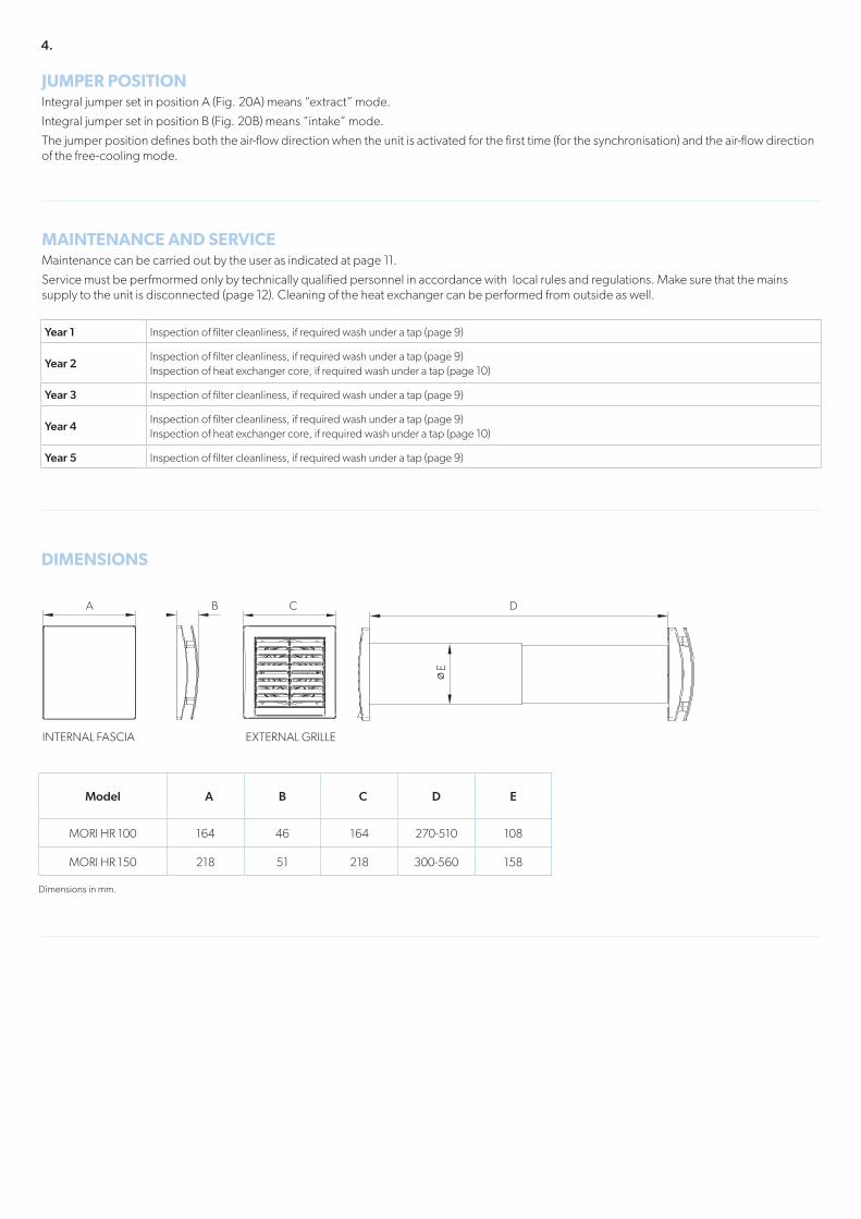
JUMPER POSITIONIntegral jumper set in position A (Fig. 20A) means “extract” mode.
Integral jumper set in position B (Fig. 20B) means “intake” mode.
The jumper position defines both the air-flow direction when the unit is activated for the first time (for the synchronisation) and the air-flow direction of the free-cooling mode.
DIMENSIONS
Year 1 Inspection of filter cleanliness, if required wash under a tap (page 9)
Year 2Inspection of filter cleanliness, if required wash under a tap (page 9)Inspection of heat exchanger core, if required wash under a tap (page 10)
Year 3 Inspection of filter cleanliness, if required wash under a tap (page 9)
Year 4Inspection of filter cleanliness, if required wash under a tap (page 9)Inspection of heat exchanger core, if required wash under a tap (page 10)
Year 5 Inspection of filter cleanliness, if required wash under a tap (page 9)
205205
D
E
Dimensions in mm.
Model A B C D E
MORI HR 100 164 46 164 270-510 108
MORI HR 150 218 51 218 300-560 158205205
A
205205
B
205205
C
EXTERNAL GRILLEINTERNAL FASCIA
5.
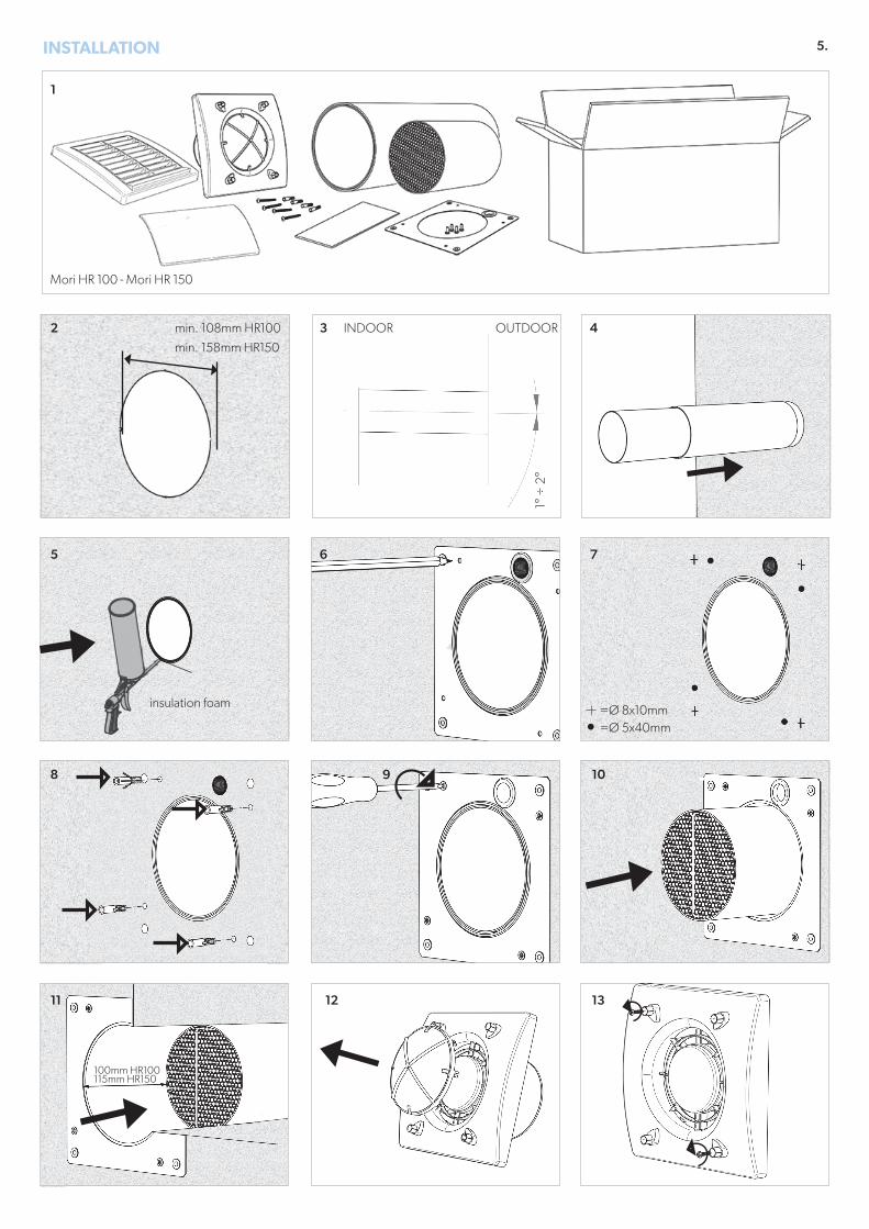
insulation foam
Mori HR 100 - Mori HR 150
INSTALLATION
min. 108mm HR100
min. 158mm HR150
OUTDOOR
1° ÷
2°
=Ø 5x40mm=Ø 8x10mm
2
5
8
11 12
9 10
13
3
6 7
4
1
INDOOR
100mm HR100115mm HR150
6.
AGGIUNTA FOGLIO ISTRUZIONI -
EXTRACT
S3
S2
S1
GN
DN
L
CTRL-SS1 S2 S3
III
N
LOK
1 1 1
S 3 S 2 S 1
S3
S2
S1
GN
DN
L
S1 S2 S3
III
N
LOK
S3
S2
S1
GN
DN
L
CTRL-S
1 1 1
S 3 S 2 S 1
S3 S2 S1 GN
DN
L
S3 S2
S1 G
ND
NL
S3 S2
S1 G
ND
NL
S3
S2
S1
GN
DN
L
CTRL-SS1 S2 S3
III
N
LOK
1 1 1
S 3 S 2 S 1
S3 S2 S1 GN
DN
L
S3 S2
S1 G
ND
NL
14
17
15
18a
18c
18f
19
18d
18f
18e
18g
SPEED 1 (FIXED)
SPEED 3 (FIXED) SPEED 1 TO 3 SPEED 2 TO 3
SPEED 2 (FIXED)
16
18b
JUMPER POSITION A20a
7.
CLICK
AGGIUNTA FOGLIO ISTRUZIONI -
JUMPER POSITION B20b
23
22
INTAKE
21
24
27
25
26
EXTERNAL GRILLE
28 2928 Ø 5x40mm3-5mm 30
8.
TO RESET OF THE SYNCHRONIZATION OF THE UNITS (OPTION 1)
TO RESET OF THE SYNCHRONIZATION OF THE UNITS (OPTION 2)
31
32 33
9.
FILTER CLEANING (MAINTENANCE)Can be carried out by the user.
34
37
35
38
36
39
I
4140
I
10.
HEAT EXCHANGER CLEANING (SERVICE)Must be carried out only by technically qualified personnel
100mm HR100115mm HR150
51
52
53
42 43
45
44
46 47
48 49 50
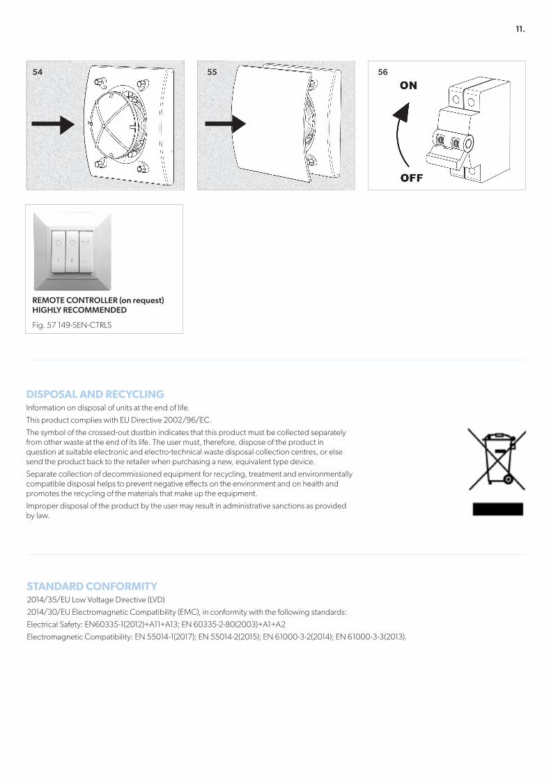
11.
54 55 56
I I I
REMOTE CONTROLLER (on request) HIGHLY RECOMMENDED
Fig. 57 149-SEN-CTRLS
DISPOSAL AND RECYCLINGInformation on disposal of units at the end of life.
This product complies with EU Directive 2002/96/EC.
The symbol of the crossed-out dustbin indicates that this product must be collected separately from other waste at the end of its life. The user must, therefore, dispose of the product in question at suitable electronic and electro-technical waste disposal collection centres, or else send the product back to the retailer when purchasing a new, equivalent type device.
Separate collection of decommissioned equipment for recycling, treatment and environmentally compatible disposal helps to prevent negative effects on the environment and on health and promotes the recycling of the materials that make up the equipment.
Improper disposal of the product by the user may result in administrative sanctions as provided by law.
STANDARD CONFORMITY2014/35/EU Low Voltage Directive (LVD)
2014/30/EU Electromagnetic Compatibility (EMC), in conformity with the following standards:
Electrical Safety: EN60335-1(2012)+A11+A13; EN 60335-2-80(2003)+A1+A2
Electromagnetic Compatibility: EN 55014-1(2017); EN 55014-2(2015); EN 61000-3-2(2014); EN 61000-3-3(2013).
WARRANTYOur 5 year warranty is provided only to customers who purchased directly from us. If you purchased elsewhere then please contact them directly and they will let you know their warranty procedure. Our warranty covers repair or replacement of defective goods only. It does not cover any labour costs associated with defective product or component removal or installation, nor does it cover the cost of sending goods back to us for inspection. Our warranty is subject to storage, installation, commissioning, inspection and maintenance having been carried out in accordance with our Installation and Maintenance Instructions (supplied with each product) and which are also available to view, save or print from our website.
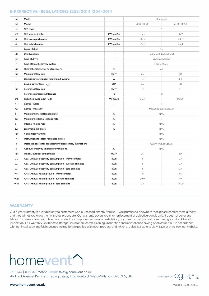
ErP DIRECTIVE - REGULATIONS 1253/2014 1254/2014
a) Mark - Homevent
b) Model - MORI HR 100 MORI HR 150
c) SEC class - A
c1) SEC warm climates kWh/m2.a -15.6 -16.2
c2) SEC average climates kWh/m2.a -37.5 -38.2
c3) SEC cold climates kWh/m2.a -75.6 -76.4
Energy label - Yes
d) Unit typology - Residential - bidirectional
e) Type of drive - Multi-speed drive
f) Type of Heat Recovery System - Heat recovery
g) Thermal efficiency of heat recovery % 74
h) Maximum flow rate m3/h 25 60
i) Electric power input at maximum flow rate W 2.6 3.8
j) Sound power level (LWA) dBA 35 38
k) Reference flow rate m3/h 17 41
l) Reference pressure difference Pa 10
m) Specific power input (SPI) W/m3/h 0.071 0.054
n1) Control factor - 1
n2) Control typology - Manual control (no DCV)
o1) Maximum internal leakage rate % N/A
o2) Maximum external leakage rate % 1
p1) Internal mixing rate % N/A
p2) External mixing rate % N/A
q) Visual filter warning - N/A
r) Instructions to install regulated grilles - N/A
s) Internet address for preassembly/disassembly instructions - www.homevent.co.uk
t) Airflow sensitivity to pressure variations % N/A
u) Indoor/outdoor air tightness m3/h 21 60
v1) AEC - Annual electricity consumption - warm climates kWh 1 0.7
v2) AEC - Annual electricity consumption - average climates kWh 1 0.7
v3) AEC - Annual electricity consumption - cold climates kWh 1 0.7
w1) AHS - Annual heating saved - warm climates kWh 18 18.1
w2) AHS - Annual heating saved - average climates kWh 39.9 40
w3) AHS - Annual heating saved - cold climates kWh 78 78.2
MORI HR . ISSUE A. 03.21
Tel: +44 (0) 1384 275822, Email: [email protected] Third Avenue, Pensnett Trading Estate, Kingswinford, West Midlands, DY6 7US, UK
www.homevent.co.uk